1
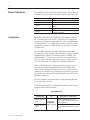
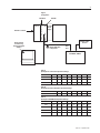
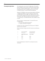
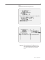
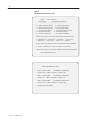
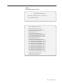
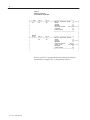
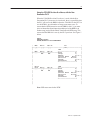
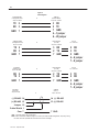
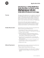
Application Note
" % " % #!
" $" "
%
# "
% " " Overview
The purpose of this application note is to explain how to interface the
2755-DS/DD Bar Code Decoder to the 2760-RB Network Interface
Module via Allen Bradley’s proprietary DH485 communications
protocol using the 2760-SFC2 protocol cartridge. Up to thirty one
decoders can be interfaced to each of the three network interface
ports for a total of up to ninety three decoders per 2760-RB module.
This document includes cable diagrams and configuration
information for the 2760-RB and the 2755-DS/DD decoder. Also
included is an introductory PLC program necessary to establish
communication from the PLC to the 2760-RB interface module.
Hardware Requirements
Implementation of the procedure described in this application note
requires the following Allen-Bradley hardware:
• Allen Bradley 2755 family of unattended bar code decoders.
• Bulletin 2760-RB in a Bulletin 1771 rack with a PLC-5 processor
• 2760-SFC2 protocol cartridge.
• Personal computer (PC) with terminal emulator software or
VT-100 type terminal to configure the 2755-DS/DD bar code
decoder and the 2760-RB network interface module
• Appropriate cables to program the PLC-5 and configure the
Bulletin 2755 bar code decoder. Refer to hardware manuals for
cable requirements.
• Catalog Number 1784-KT or equivalent card installed in your
personal computer to enable you to program the PLC-5.
• DH485 network cables.
Software Requirements
Implementation of the procedure described in this application note
requires the following Allen-Bradley software:
• Bulletin 6200 development software for the PLC-5
• Terminal Emulation Package (such as Procomm or Windows
Terminal) if a personal computer is used to configure the 2755
DS/DD.
2755-2.55 – September 1995
2
Related Publications
This document refers to the following publications, which should be
available for reference while working through this application note:
Publication Number
Configuration
Title
1785-XXX
User Manual for your PLC-5
6200-XXX
Programming Manual for your PLC-5
2755-833
Bulletin 2755-DS/DD Enhanced Decoder User
Manual
2760-ND001
Bulletin 2760 Flexible Interface Module User Manual
2755-822
Bulletin 2760 RS485 LAN Master/Slave Protocol
Cartridge User Manual
Mount the Catalog Number 2760-RB interface module in Slot 0 of
the 1771 chassis (next to the PLC). The Bulletin 2755-DS/DD bar
code decoder communicates through Port 1 of the 2760-RB module.
A Catalog Number 1771-ASB interface module can also be used to
communicate with the 2760-RB module over the chassis backplane
via Remote I/O.
The 2760-RB configuration example in this document includes
configuration screens and DIP switch settings necessary to establish
communications with the 2755-DS/DD decoder via DH485. The
2760-RB and the 1771 chassis are set up for two slot addressing.
There are other 2760-RB configuration features available and not
used. See Publication 2760-ND001 for additional information.
The 2755-DS/DD decoder configuration shows only the screens
necessary to establish communications to the 2760-RB module.
Other decoder configuration parameters such as selecting bar code
symbology or a decoder trigger method are beyond the scope of this
document. See the Decoder User Manual Publication 2755-833 for
additional information.
The PLC program is a minimum mode example showing that data
can be moved into the PLC.
Use the following table as a configuration guideline when using the
examples shown in this document.
PLC 5 COMPATABILITY
2760-RB In Use
Series A, Rev. G or
below
Series A, Rev H or
Above
2755-2.55 – September 1995
PLC-5, -15, -25,
etc.
Follow example
PLC program as
w in Figure No.
N .
shown
4.
New Generation PLC-5
(Series A, Rev. C or above only)
Set BT Compatibility Bit S26/4 while in
program mode. Use example PLC program
shown Figure No. 4.
Add ladder logic using IIN update of RB.
BTR must be before ‘BTW. Refer to Figure
No. 5
3
Figure 1
Configuration
2760-SFC2
PLC-5
2760-RB
1771-P4
Power
Supply
Bulletin 1771 Rack
Bulletin 2755-L
Scanner
Dumb Terminal
or PC Running
Terminal Emulation
Software
DH485
Host
Port
Beldon 9842 Cable
or Equivalant
2755-DD/DS, -DM6/9
Table A
(Example) PLC-5 Processor Dip Switch Settings
Switch No.
1
2
3
4
5
6
7
8
SWI-1
on
on
on
on
on
on
on
off
SWI-2
off
on
on
on
on
on
on
off
SW-3
on
on
off
off
Table B
(Example) I/O Chassis Backplane Dip Switch Settings
1
2
3
4
5
6
7
8
off
off
off
off
off
on
off
off
Table C
(Example) 2760-RB Module Dip Switch Settings
Switch No.
1
2
3
4
5
6
7
8
SWI-1
off
off
off
off
off
off
off
off
SWI-2
off
off
off
off
off
off
off
off
SW-3
off
off
off
off
SW-4
off
off
on
off
2755-2.55 – September 1995
4
Running the Application
The configuration screens for the 2760-RB and the 2755-DS/DD
decoder should be entered exactly as shown in the following pages.
Save them, and then restart the decoder. Connect a network cable
from the host port of the 2755-DD/DS decoder to port #1 of the
2760-RB. See Figure 6 for cable construction information.
When the 2755-DS/DD is in the network mode (RS485 ASCII Mode
1 or RS485 ASCII Mode 2) it will be waiting for a poll from the
2760-RB module. If the 2760-RB is not configured to poll a node
that is physically installed on the network, the decoder will refuse to
read any bar codes. When the decoder has valid bar code data or a
”no read message” it will transmit the data to the 2760-RB on receipt
of a poll.
You can recognize “Normal operation ” by green LED’s on the
2760-RB module
• The Active/Fault LED will flash green.
• The Port 1 LED will be dim green.
In addition, the yellow Communication LED on the 2755-DS/DD
Decoder will be “Solid ON”.
The bar code data will appear in the PLC data table in the following
format:
0
BYTE COUNT IN BCD
BYTE COUNT IN BCD
1
DATA SOURCE
DATA DESTINATION
2
LSAP NUMBER (ALWAYS
80H)
NODE NUMBER
3
DATA
DATA
4
DATA
DATA
5
DATA
DATA
See the 2760-RB and the 2760-SFC2 User Manuals for further
information.
2755-2.55 – September 1995
5
Figure 2
2755-DS/DD Host Communications Configuration Screens
Important: When configuring the 2760-RB module, first
select “Main Menu Selection 90B” to reset the
unit to factory defaults. Then configure screens
3, 21, and 11 in that order exactly as shown
below.
2755-2.55 – September 1995
6
Figure 3a
2760-RB Module Configuration Screens
2760–RB
SERIES A REVISION J
COPYRIGHT 1989
ALLEN–BRADLEY COMPANY, INC.
––––––––––––––––––––––––––––––––––––––––––––––––––––
1X – CONFIGURATION PARAMETERS
2X – IDENTIFICATION NUMBERS
3 – DEVICE PORT PROTOCOL NAMES
4DM – MATCH CODE ENTRIES
5I – DISCRETE BYTE INPUT ENTRIES
6 – THE DATA MATRIX ENTRIES
7 – THE PASS THROUGH ENTRIES
8 – NON–VOLATILE SCRATCH PAD AREA
9XF – RB MODULE FUNCTIONS
AX – HARDWARE DIAGNOSTICS
BX – SOFTWARE DIAGNOSTICS
C – EXIT CONFIGURATION MODE
WHERE X (0 TO 7) AND D (1 TO 3) ARE PORT NUMBERS WHICH ARE DEFINED BELOW :
0 – RB CMMND PRCSS 2 – SERIAL PORT 2 4 – CONFIG PORT 6 – I/O RACK SLT 1
1 – SERIAL PORT 1 3 – SERIAL PORT 3 5 – I/O RACK SLT 0 7 – RESERVED
WHERE F (A TO E) ARE FUNCTIONS THAT RB CAN PERFORM WHICH ARE DEFINED BELOW :
A – RESET B – SET DEFAULTS C – FLUSH D – INITIALIZE E – CLEAR DIAGS
WHERE M (A TO T) AND I (A TO H) ARE ENTRY NUMBERS FOR THE SELECTION MADE ABOVE.
ENTER A MAIN MENU SELECTION:
ENTER A MAIN MENU SELECTION: 3
PORT 1 = COPYRIGHT 1989
ALLEN–BRADLEY COMPANY, INC.
2760–SFC2 LAN , SERIES A , REVISION A (YES/NO) = YES.
PORT 2 = COPYRIGHT 1989
ALLEN–BRADLEY COMPANY, INC.
2760–SFC2 DT , SERIES A , REVISION A (YES/NO) = YES.
PORT 3 = COPYRIGHT 1989
ALLEN–BRADLEY COMPANY, INC.
2760–SFC2 LAN , SERIES A , REVISION A (YES/NO) = YES.
EDIT THIS SELECTION (YES/NO) ?
2755-2.55 – September 1995
7
Figure 3b
2760-RB Module Configuration Screens
ENTER A MAIN MENU SELECTION: 21
RS485 LAN 2755-DM6 ASCII MODE 3, 0h (YES/NO) = YES
EDIT THIS SELECTION (YES/NO) ?
ENTER A MAIN MENU SELECTION: 11
SLOT TIME (NO. CHARS) (DEC 0...255) = 7.
INTER-CHAR TIME (NO. CHARS) (DEC 0...255) = 7.
IDLE TIME (NO. CHARS) (DEC 0...255) = 3.
RETRIES (DEC 0...255) = 3.
19200 BITS PER SECOND (YES/NO) = YES.
BCD NODE NUMBERS (ENABLE/DISABLE) = ENABLE.
BYTE SWAPPING (ENABLE/DISABLE) = ENABLE.
RECEIVE MATRIXING (ENABLE/DISABLE) = DISABLE.
MATRIX ADDRESS (HEX 0...ffff) = 0.
RE–ESTABLISH FREQUENCY (DEC 0...255) = 5.
POLL FREQUENCY/DESTINATION[0] (HEX 0...ffff) = 5.
POLL FREQUENCY/DESTINATION[1] (HEX 0...ffff) = 105.
POLL FREQUENCY/DESTINATION[2] (HEX 0...ffff) = 5.
POLL FREQUENCY/DESTINATION[3] (HEX 0...ffff) = 5.
POLL FREQUENCY/DESTINATION[4] (HEX 0...ffff) = 5.
POLL FREQUENCY/DESTINATION[5] (HEX 0...ffff) = 5.
POLL FREQUENCY/DESTINATION[6] (HEX 0...ffff) = 5.
POLL FREQUENCY/DESTINATION[7] (HEX 0...ffff) = 5.
POLL FREQUENCY/DESTINATION[8] (HEX 0...ffff) = 5.
POLL FREQUENCY/DESTINATION[9] (HEX 0...ffff) = 5.
POLL FREQUENCY/DESTINATION[10] (HEX 0...ffff) = 5.
CONTINUE THIS SELECTION (YES/NO) ?
EDIT THIS SELECTION (YES/NO) ?
2755-2.55 – September 1995
8
Figure 4
Sample PLC Program
PLC 5/15/25 Etc. to 2760-RB
| I:000
N7:0
N7:5
+–––––––––––––––––––––––+
|
+–––] [–––––]/[––––––]/[––––––––+Block Transfer Read
+––O––+
|
13
15
15
|Rack
0|
|
|
|Group
1|
|
|
|Module
0|
|
|
|Control Block
N7:100+––O––+
|
|Length
0|
|
|
|Continuous
N|
|
|
+–––––––––––––––––––––––+
|
|
|
|
|
|
Write
|
|
Data
N7:0
N7:5
+–––––––––––––––––––––––+
|
+–––] [–––––]/[––––––]/[––––––––+Block Transfer Write
|
|
|
15
15
|Rack
0|
|
|
|Group
1+––O––+
|
|Module
0|
|
|
|Control Block
N7:5|
|
|
|Data File
N7:200+––O––|
|
|Length
0|
|
|
|Continuous
N|
|
|
+–––––––––––––––––––––––+
|
|
|
Refer to your PLC-5 Instruction Reference Manual for detailed
information on using the PLC-5 programming software.
2755-2.55 – September 1995
9
Using the 2760-RB, Revision H or Above, with the New
Generation PLC5
When the 2760-RB, Revision H or above, is used with the New
Generation PLC5 processors in a local rack, there is a possibility that
the PLC will not see the BRR bit from the 2760-RB. For the PLC5 to
see the BTR bit, an odd number of image scans must occur. To
ensure that the BTR instruction sees the BRR bit (bit 13) you must
place an Immediate Input Instruction addressed to the BRR bit in
another rung just before the Block Transfer Read (BTR) rung. This
ensures that the BRR bit is seen by the NP-5 processor. See Figure 5
below.
Figure 5
Sample PLC Program
2760-RB, Revision H or J to PLC 5/20/30/40/50
|
BRR
BT7:5
BT7:25
001
|
+–––]/[–––––]/[––––––]/[–––––––––––––––( IIN )––––––––––––––––+
|
|
|
BTR
|
|
BRR
BT7:5
BT7:25
+––––––––––––––––––––––+
|
+–––] [–––––]/[––––––]/[–––––––––+Rack
0|
|
|
EN
EN
|Group
1|
|
|
|Module
0+––O––+
|
|Control Block
BT7:5|
|
|
|Data File
N7:200|
|
|
|Length
0+––O––+
|
|Continuous
N|
|
|
+––––––––––––––––––––––+
|
|
|
|
|
|
Write
BTW
|
|
Data
BT7:5
BT7:25
+––––––––––––––––––––––+
|
+–––] [–––––]/[––––––]/[–––––––––+Rack
0|
|
|
EN
EN
|Group
1|
|
|
|Module
0+––O––+
|
|Control Block
BT7:25|
|
|
|Data File
N7:400|
|
|
|Length
0+––O––+
|
|Continuous
N|
|
|
+––––––––––––––––––––––+
|
|
|
|
|
|
|
|
|
Note: BTR must come before BTW.
2755-2.55 – September 1995
10
Figure 6
Cable diagrams
2760-RB Module
(Configuration Port)
25-pin “D”, Male
to
TX 2
RX 3
3 RX
2 TX
7 GND
4 – 5 jumper
6 – 20 jumper
GND 7
2760-RB Module
(Configuration Port)
25-pin “D”, Male
to
Dumb Terminal
(VT-100)
25-pin “D”, Female
3 RX
2 TX
7 GND
TX 2
RX 3
GND 7
2755-DSIA
(Auxiliary Port)
25-pin “D”, Male
to
RX 2
TX 3
GND 7
2755-DSIA
(Host Port)
25-pin “D” male
1784-T45
(Terminal Mode)
25-pin “D”, Female
Dumb Terminal
(VT-100)
25-pin “D”, Female
2 TX
3 RX
7 GND
to
2760-RB
(Port 1) *
25-pin “D” male
(–) RS-485 14
14 (–) RS-485
(+) RS-485 13
Jumper 12
15 (+) RS-485
Cable Shield 1
Com 7
7 GND
Note: Use Beldon 9842 Cable or Equivalant.
*Note: Refer to Publication 2760-822 (Pages 4-11 and 5-5) for further RS-485 wiring details, especially if using
the node connectors provided with the 2760-SFC2 Protocol Cartridges.
2755-2.55 – September 1995
or 9-pin
PC Com Port
2 RX
3 TX
5 GND
4 – 6 jumper
7 – 8 jumper
or 9-pin
PC Com Port
3 TX
2 RX
5 GND
4 – 6 jumper
7 – 8 jumper
11
Notes:
2755-2.55 – September 1995
SLC 5/03, SLC 5/04, DH+, and INTERCHANGE are trademarks of Allen-Bradley Company, Inc.
OS/2 is a registered trademark of International Business Machines, Incorporated.
Gateway 2000 and COLORBOOK are trademarks of Gateway 2000, Inc.
Microsoft and MS are registered trademarks, and Windows is a trademark of Microsoft Corp.
VERSA is a trademark of Nippon Electric Information Systems Inc.
Allen-Bradley, a Rockwell Automation Business, has been helping its customers improve
productivity and quality for more than 90 years. We design, manufacture and support a broad
range of automation products worldwide. They include logic processors, power and motion
control devices, operator interfaces, sensors and a variety of software. Rockwell is one of the
worlds leading technology companies.
Worldwide representation.
Argentina • Australia • Austria • Bahrain • Belgium • Brazil • Bulgaria • Canada • Chile • China, PRC • Colombia • Costa Rica • Croatia • Cyprus • Czech Republic •
Denmark • Ecuador • Egypt • El Salvador • Finland • France • Germany • Greece • Guatemala • Honduras • Hong Kong • Hungary • Iceland • India • Indonesia •
Ireland • Israel • Italy • Jamaica • Japan • Jordan • Korea • Kuwait • Lebanon • Malaysia • Mexico • Netherlands • New Zealand • Norway • Pakistan • Peru •
Philippines • Poland • Portugal • Puerto Rico • Qatar • Romania • Russia–CIS • Saudi Arabia • Singapore • Slovakia • Slovenia • South Africa, Republic • Spain •
Sweden • Switzerland • Taiwan • Thailand • Turkey • United Arab Emirates • United Kingdom • United States • Uruguay • Venezuela • Yugoslavia
Allen-Bradley Headquarters, 1201 South Second Street, Milwaukee, WI 53204 USA, Tel: (1) 414 382-2000 Fax: (1) 414 382-4444
Publication 2755-2.55 – September 1995
40062-320-01(A)
Copyright 1995 Allen-Bradley Company, Inc. Printed in USA
1