1
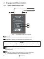
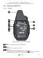
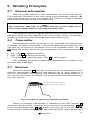
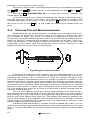
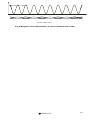
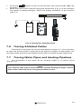
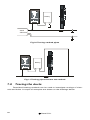
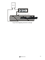
INSTRUCTION MANUAL WIRE TRACER LKZ-710 Version 1.6 11 March, 2010 Wire tracer LKZ-710 is intended to locate electrical cabling embedded in different materials (concrete, bricks, timber) in buildings. The cables can be detected regardless whether they are live or not. Tracer’s main features: • • • • 2 Detection of cables in ceilings, walls and floors, Detection of the place of shorted circuits (using an external power source), Locating of switches and fuses, Identification of cables in an installation. Sonel S.A. CONTENTS 1 INTRODUCTION .................................................................... 5 2 SAFETY .................................................................................... 6 3 PREPARING THE DEVICE FOR WORK ........................... 7 4 EQUIPMENT DESCRIPTION ............................................... 8 TRANSMITTER LKN-710 ...................................................... 8 4.1 RECEIVER LKO-710 ............................................................. 9 4.2 Panel .............................................................................. 9 4.2.1 Sound signals ............................................................... 10 4.2.2 LEADS ................................................................................. 10 4.3 5 WORKING PRINCIPLES .................................................... 11 GENERAL INFORMATION ..................................................... 11 TRANSMITTER ..................................................................... 11 RECEIVER ........................................................................... 11 CLOSED-CIRCUIT MEASUREMENTS..................................... 12 5.1 5.2 5.3 5.4 6 SYSTEM WORKING MODE............................................... 14 7 MEASUREMENTS ................................................................ 15 7.1 7.2 7.2.1 7.3 7.4 7.5 7.6 7.7 7.8 AMPLIFICATION (SENSITIVITY) ADJUSTMENT ...................... 15 DETECTION OF CABLES IN CEILINGS, WALLS AND FLOORS 16 Live Cables .................................................................. 16 IDENTIFICATION OF FUSES ON THE DISTRIBUTION BOARD .. 17 LOCATING SHORT CIRCUITS BETWEEN LEADS .................... 18 TRACING THE SHIELDED WIRES ........................................... 18 TRACING SHIELDED CABLES............................................... 19 TRACING WATER PIPES AND HEATING PIPELINES............... 19 TRACING THE DUCTS ........................................................... 20 8 TROUBLE SHOOTING ........................................................ 22 9 POWER SUPPLY .................................................................. 22 BATTERIES .......................................................................... 22 REPLACEMENT OF BATTERIES IN THE RECEIVER................. 22 9.1 9.2 10 CLEANING AND MAINTENANCE ................................... 23 11 STORAGE .............................................................................. 23 12 DECOMMISSIONING AND RECYCLING ....................... 23 13 APPENDICES ........................................................................ 24 13.1 TECHNICAL SPECIFICATIONS .............................................. 24 Sonel S.A. 3 13.2 13.3 13.4 4 STANDARD ACCESSORIES ................................................... 24 OPTIONAL ACCESSORIES .................................................... 24 THE MANUFACTURER ......................................................... 25 Sonel S.A. 1 Introduction Thank you for choosing our wire tracer. LKZ-710 is a state of the art, high quality device that is simple and safe to operate. Nevertheless familiarization with this manual will help you avoid errors and possible problems that might occur while using the device. This instruction manual uses three types of warnings. They are framed texts describing possible threats for a user and for the equipment. Texts that start with a word “WARNING:” describe situations that can become hazardous if the instructions are not followed. The word “NOTE!” at the beginning of the framed text signals a situation where non-adherence to the instruction can damage the equipment. Other possible problems are signalled by a “Note:” flag. WARNING: Before using the device read carefully this manual, follow all occupational health and safety rules and manufacturer’s recommendations. WARNING: LKZ-710 is intended for searching and locating power lines in walls. Using the device for purposes other then described in this manual can cause an injury to the operator and/or can damage the device. WARNING: LKZ-710 may be used only by qualified personnel who are certified to work with electrical installations. Operating the instrument by a person who is not qualified, can result in a hazardous situation and/or can cause damage to the device. Sonel S.A. 5 2 Safety WARNING: Using a device that has damaged housing or with leads that have damaged insulation can be a source of a safety hazard. To ensure proper use and correctness of obtained results adhere to the following recommendations: • • • • Before starting to use the device, you have to become thoroughly familiar with this manual. The device should be operated only by persons holding appropriate qualifications and who attended appropriate occupational health and safety training. It is not acceptable to: ⇒ use the device that is damaged in any way and is partially or fully inoperative, ⇒ use leads with damaged insulation, ⇒ use the meter stored in inappropriate conditions (e.g. high humidity) for a prolonged period of time. Repairs can be performed by authorised service agents only. NOTE! The transmitter is designed to work with a rated voltage of 230V. Connecting the device to a voltage that exceeds 250VAC can damage the instrument. WARNING: The instrument must not be used with installations or equipment situated in dangerous environments, e.g. where fire or explosion hazards exists. 6 Sonel S.A. 3 Preparing the Device for Work Before you start locating cables check if the transmitter’s housing and leads’ insulation are not damaged. WARNING: Using leads with damaged insulation can case electrocution. WARNING: You must not leave one lead disconnected from the device while the other one is connected to the tested installation. You must not leave the device connected to the tested installation without supervision. WARNING: Do not use a device that was stored for a prolonged period of time in unsuitable (e.g. humid) conditions. Sonel S.A. 7 4 Equipment Description 4.1 Transmitter LKN-710P 1 2 MAX 250 V RMS CAT III 300V LKN-710P - LKZ-710 - P-3 OUTPUT POWER MODE 4 3 Serial No: ABN: 45 206 766 437 Fig. 1. Transmitter of the tracer (panel) 1 test lead Lead used to connect the transmitter with the tested circuit. 2 test lead Lead used to connect the transmitter with the tested circuit. NOTE! The transmitter is designed to work with a nominal voltage of 230 V. Using the transmitter with a voltage higher than 250 V AC may damage the device. 3 OUTPUT POWER MODE button Setting the output power of the transmitter. Mode switching. 4 LED Indicates the working mode and power level of the transmitter: • red colour of shining – LKZ-710 working mode - LED is blinking slowly – small transmitter power 8 Sonel S.A. • 4.2 - LED is blinking quickly – big transmitter power green colour of shining – P-3 voltage tester working mode Receiver LKO-710 4.2.1 Panel 5 11 10 12 M 9 14 TRANSMITTER 13 M 8 6 7 MODE LKO-710 Fig. 2. Receiver of the tracer (panel) 5 Head Contains a magnetic and electric field detector. 6 7 button Allows to turn the receiver on and off. • • button Decreasing the subrange (sensitivity) of the receiver. Press this button in combination with the 8 button to change the working mode: current or non-contact voltage tester mode. Sonel S.A. 9 8 • • button Increasing the subrange (sensitivity) of the receiver. Press this button in combination with the 7 button to change the working mode: current or non-contact voltage tester mode. 9 LED indicator Shows the subrange of the receiver and the intensity of the magnetic or electric field. 10 “M” LED Indicates that the current circuit of the receiver is active. 11 LED Indicates that the non-contact voltage tester mode is active. 12 LED Indicates that the battery is discharged. 13 “TRANSMITTER M” DIODE Indicates detection of the transmitter signal. 14 LED Indicates detection of the 50/60 Hz electric field from the phase leads (noncontact voltage tester mode). 4.2.2 Sound signals Confirmation signals and others: Single short sound signal • change of the “sensitivity subrange” Two short sound signals • activation or deactivation of the subrange indication Three short sound signals • change of the receiver working mode Single long sound signal (approx. 0.5 s) • indicates that the lowest or highest subrange has been reached • indicates that the button is not active 4.3 Leads Crocodile clips and probes provided with the leads can be placed on cable terminators. WARNING: Using damaged leads with the transmitter can be dangerous for the operator of the device. 10 Sonel S.A. 5 Working Principles 5.1 General Information LKZ-710 system consists of two components: transmitter and receiver. The transmitter connected to the circuit being traced generates magnetic („M” mode) field around the circuit. It is created as a result of a suitably modulated current flowing through the tested (closed) circuit. Note: The transmitter LKN-710P co-operates with the receiver LKO-710 as well as with voltage tester P-3 (see Manual LKN-710P). The transmitter placed alongside the tested circuit detects the modulated field and notifies the user. Mapping of the circuit (cable) route or its defects is possible through observation of the detected signal intensity level. 5.2 Transmitter Electromagnetic signals broadcast by the transmitter are appropriately modulated. Therefore it is possible to differentiate between them and other signals that may be present in the tested circuit or its immediate vicinity. The 3 button can be also used to set (also sequentially) one of two power levels: OUTPUT POWER MODE • • • low – LED 4 is blinking red slowly high – LED 4 is blinking red quickly P-3 voltage tester working mode – LED 4 is shining green LED remaining switched off signals that the tested circuit is dead or that the transmitter is damaged. 5.3 Receiver Receiver’s antenna 5 hides two sensors: an electric field detector and a magnetic field detector. The electric field detector has an aerial shaped in a form of a metal plate. The magnetic field detector has an aerial shaped as a coil. The way the aerials are located (Fig. 3) influences directional characteristics of the receiver. An electric f ield detector’s antenna A magnetic field detector’s antenna Fig.3 Location of sensors in receiver’s antenna Electric or magnetic field strength is indicated by the LED indicator 9 “deflection” (blinking LED). Sensitivity of the receiver is increased with 8 button and decreased with 7 button. Pressing one of the two buttons causes litting of LEDs illustrating currently used sensitivity range and the next Sonel S.A. 11 pressing – its increasing or decreasing. Receiver’s work mode is switched sequentially by simultaneous pressing the 7 and 8 buttons which is accompanied by LED 10 M or 11 being lit. The LED 13 TRANSMITTER M is lit when the receiver indicates the transmitter’s signal. In the non-contact neon mode the receiver can detect if the tested line is live and can also locate a live cable. The receiver detects an electric field 50/60Hz displaying its strength on the LED gauge 9 and after exceeding certain level it turns on the 14 work. 5.4 . In this mode the switching of ranges does not Closed-Circuit Measurements Measurements can be performed in a closed circuit provided that a current flow can be induced in the circuit. This is the case in a healthy line with line’s voltage of 230V (the circuit is closed by a transformer) and also in a shorted line, using the external power source. In all described situations the detection is done by evaluating the magnetic component of the field. Fig.4 illustrates the direction of the magnetic field lines around the cable in which the modulated current flows, and the placement of the receiver allowing for the highest possible intensity of the received signal. A C B Fig.4 Magnetic field detection Directional properties of the receiver can be observed when we try to change its position in relation to the cable in directions indicated by the arrows. Swinging the receiver only in directions “A” does not change the signal level since the magnetic field detector does not change is position in relation to the magnetic field lines. On the other hand, rotating the receiver around its axis (arrow “C”) will cause gradual signal deterioration until it disappears when rotating the device by 90º. Similarly, when swinging the receiver in direction “D” (around the axis of the receiver’s aerial). Also moving the receiver away from the cable (“B”) will weaken the signal as a result of a decrease in field’s strength with an increase of the distance. For a 2-core cable in which the current flows through one of the cores in one direction and in the opposite direction through the other core, the magnetic field strength is much lower than in a single-core cable since the fields generated by the cores cancel each other out. The greater the distance between the cores, the stronger is the magnetic field. This phenomenon is utilised for detecting all sorts of inconsistencies in power lines e.g. cable boxes, switches, stub cables, cable ducts constrictions etc. A different field distribution is created around a twisted pair cable. It is not uniform and changes periodically depending on the relative position of the cores (Fig. 5). It has to be taken into account when tracking a cable or locating cable faults. 12 Sonel S.A. Magnetic field intensity Cable length Twisted pair ca ble Fig.5 Magnetic field distribution around a twisted pair cable Sonel S.A. 13 6 System working mode The system operates in the “M” current mode and can be used with undamaged leads under a voltage of 230 V AC or in closed circuits (for example, shorted leads). It uses external direct current (minimum 12 V) or an alternating current source (minimum 24 V). NOTE! The transmitter is designed to work with the rated voltage of 230V. Connecting the device to a voltage that exceeds 250VAC can damage the instrument. One of the transmitter’s output terminals is connected to the phase wire of the tested cable and the other one to the neutral wire. The voltage that exists in this circuit is used by the transmitter to generate a current signal (max 20mA) in a form of high frequency impulses with the amplitude modulated by a lower frequency signal distributed over the time in the specific way. The magnetic component of the field generated in this way is then detected by the receiver. 14 Sonel S.A. 7 Measurements NOTE! The transmitter is designed to work with the rated voltage of 230V. Connecting the device to a voltage that exceeds 250VAC can damage the instrument. WARNING: You must not leave one lead disconnected from the device while the other one is connected to the tested installation. You must not leave the device connected to tested installation without supervision. WARNING: Always connect the transmitter to the ground first and only than to the phase wire. Note: It is necessary to use a power source strong enough to generate a proper test current. When the current is generated, the 4 LED flashes. Note: In objects with working appliances, the receiver may display a level of noise signals. You should take into account the signal level only if the LED 13 „M” is on. Note: You have to recon with incorrect readings due to induction of current signals in closed circuits in buildings (window frames, metal framework, concrete reinforcements etc.). 7.1 Amplification (sensitivity) adjustment The amplification level of the receiver is adjusted gradually, by choosing one of six sensitivity subranges. The adjustment is performed with buttons 7 and 8 . Pressing one of the buttons will light the 9 LED at the begin- ning of the scale to indicate the currently used range (the number of lit LEDs indicates the number of the selected subrange). The LEDs will automatically extinguish after approx. 2 seconds. To increase the sensitivity (amplification), press the 8 button when LEDs indicating the current sensitivity are lit; to decrease the sensitivity, press the 7 button when LEDs indicating the current sensitivity are lit. The sensitivity should be decreased when the rightmost LED indicating the signal strength on the scale 9 will be lit; the sensitivity should be increased when the leftmost LED will light. Sonel S.A. 15 Note: The rightmost LED indicates subrange lights stronger than other LEDs, which helps to see it in strong external light. 7.2 Detection of Cables in Ceilings, Walls and Floors 7.2.1 Live Cables PE L PE N L LKN-710P LKN-710P PE L PE N LKN-710P N L N PE LKN-710P L N Fig.6 Detection of cables – different ways of connecting the transmitter Connect one of the transmitter leads 1 , 2 to the earthing system. • Note: To avoid the field compensation effect when the current flows through two cores of the cable in opposite directions, you need to use grounding (the earth or the neutral wire) situated in the remote power socket or to connect to earthed metal water pipe or to a heating pipeline (Fig. 6). In some cases, e.g. when the return current can flow through earthed structural elements of the building, it can be more beneficial for unambiguous localization of the cable to connect both leads of the transmitter to one power point. • • 16 Connect the second lead to the phase lead in the socket, switch, etc. (Fig. 6). After the transmitter is connected, the 4 LED should flash. Sonel S.A. • • • OUTPUT POWER MODE Use the 3 button to set the proper level of the transmitter output signal. Press the 6 button to turn on the receiver; the current mode (“M”) will be active. Move the head of the receiver along the tested wire (Fig. 4) in the direction the signal is getting stronger; select the proper sensitivity of the receiver (see 7.1). 7.3 • • • • • • Identification of Fuses on the Distribution Board Connect one of the transmitter leads 1 or 2 to the neutral lead of the socket; connect the second lead of the transmitter to the phase lead. After the transmitter is connected, the 4 LED should flash. Use the 3 button to set the proper level of the transmitter output signal. Press the 6 button to turn on the receiver; the current mode (“M”) will be active. Move the head of the receiver along the tested wire (Fig. 4) in the direction the signal is getting stronger; select the proper sensitivity of the receiver (see 7.1). Move the head from one fuse to another and select the proper sensitivity of the receiver (see 7.1); locate the appropriate fuse according to the maximum signal strength (Fig. 7). OUTPUT POWER MODE M P017- N KL M TRYB LKO-710 PE L N Fig.7 Identification of circuit breakers in a distribution board Note: Because modern fuses, and in particular RCDs, have inside one or more coils it may be necessary to try different ways of positioning the receiver and a number of attempts to locate a fuse will be required. Sonel S.A. 17 7.4 Locating Short Circuits between Leads WARNING: Before a measurement check if the cables are live. If yes then cut off the power. Connect one of the transmitter leads ( 1 or 2 ) to one of the shorted wires; connect the second transmitter lead to the power source (min. 12 V DC or 24 V AC) (Fig. 8). After the transmitter is connected, the 4 LED should flash. Use the 3 button to set the proper level of the transmitter output signal. Press the 6 button to turn on the receiver; the current mode (“M”) will be active. Move the head of the receiver along the tested wire (Fig. 4) in the direction the signal is getting stronger; select the proper sensitivity of the receiver (see 7.1). The signal strength decreases or the signal disappears when moving from the point of shorting. • • • OUTPUT POWER MODE • • Power source min. 12V DC or 24V AC I U LKN-710P U I -7 0 L O K Fig.8 Locating a short circuit in a cable Note: For increased accuracy of the short circuit localization the test should be repeated starting from the other end of the cable. When locating a short circuit point in a twisted pair cable you need to take into account heterogenous field distribution along the cable (Fig.5). 7.5 • • • 18 Tracing the shielded wires Connect one of the transmitter leads ( 1 or 2 ) to the shield of the wire, and the second lead to the grounded source of the direct or alternating current (Fig. 9). After the transmitter is connected, the 4 LED should flash. Use the 3 button to set the proper level of the transmitter output signal. OUTPUT POWER MODE Sonel S.A. • • Press the 6 button to turn on the receiver; the current mode (“M”) will be active. Move the head of the receiver along the tested wire (Fig. 4) in the direction the signal is getting stronger; select the proper sensitivity of the receiver (see 7.1). Battery LKN-710P UI U I L K -70 O Fig. 9 Tracing the shielded wires 7.6 Tracing Shielded Cables Procedure is the same as the one described in section 7.2. You only have to take into account that in steel ducts the signal is subject to attenuation. On the other hand aluminium and plastic ducts have no impact on the signal level. 7.7 Tracing Water Pipes and Heating Pipelines The procedure is the same as for locating cables in a closed circuit (Fig.10 i 11). Note: You need to take into account that the current flowing through a metal pipe to the earth will do so using all possible routes. Sonel S.A. 19 -7 O K L 0 Battery P017- N KL steel element Fig.10 Tracing earthed pipes -7 O L K 0 Battery UI U I P017- N KL Fig.11 Tracing pipes that are not earthed 7.8 Tracing the ducts Described locating methods can be used to investigate routings of channels and holes. A couple of examples are shown on the drawings below. 20 Sonel S.A. LKN-710P M AX 250 V RMS Battery -70 L O K UI I U Wire led through the duct Fig.12 Investigating channels routings Sonel S.A. 21 8 Trouble Shooting If the 4 LED is not lit, and the conditions for the current flow in the tested circuit are met, the transmitter is faulty. 9 Power Supply 9.1 Batteries The LKN-710P transmitter uses an external direct current (minimum 12V) or an alternating current source (minimum 24V). NOTE! Using the transmitter with a voltage higher than 250 V AC may damage the device. 9.2 Replacement of Batteries in the Receiver Fig.13. Replacement of the battery in the LKO-710 receiver Receiver LKO-710 is powered from a 6F22 9V battery. NOTE! If a battery leaks inside the instrument, send the device to a service agent. To replace the battery: 1. 2. 22 Turn the receiver off. Remove the battery cover in the bottom part of the housing: press with Sonel S.A. 3. 4. 5. your finger next to the latch and remove the cover sliding it in the direction indicated by the arrow. Remove the battery. Insert a new battery paying attention to correct orientation. Replace the removed cover. 10 Cleaning and Maintenance The housing of the meter should be cleaned with a soft, damp cloth using a general-purpose detergent. Do not use any solvents or any abrasive cleaning agents. The electronic circuitry is maintenance free. 11 Storage When storing the device you should: • Disconnect all leads from the meter • Ensure that the device and all accessories are dry • Ensure that the batteries are removed if the device is not going to be used for a prolonged period of time • Storage temperatures listed in the technical specification are acceptable 12 Decommissioning and Recycling Decommissioned electrical equipment should be stored separately from other type of waste. Decommissioned electrical equipment should be sent to an appropriate waste depot in compliance with legal acts governing electronic waste management. Do not disassemble the equipment before sending it to a waste depot. Follow local legislation regulating disposal of packaging and batteries. Sonel S.A. 23 13 Appendices 13.1 Technical Specifications a) b) c) d) e) f) g) h) i) j) k) l) m) n) o) p) Type of the transmitter insulation ............. double, PN-EN 61010-1 compliant Metrological category of the transmitter ............. III 300V wg PN-EN 61010-1 Tightness (transmitter and receiver) in accordance with PN-EN 60529 .. IP40 Transmitter’s power supply ........................................................................... .................................... external power source: AC min. 24V or DC min. 12V Receiver’s power supply ....................................... battery 6LR61 9V alkaline Transmitter’s max working voltage............................... 250Vrms (353Vampl) Transmitter’s dimensions .................................................. 128 x 66 x 28 mm Transmitter’s mass .......................................................................... ca 250 g Receiver’s dimensions ...................................................... 210 x 82 x 24 mm Receiver’s mass .............................................................................. ca 200 g Working temperature ...................................................................–20..+50°C Storage temperature .................................................................... –20..+60°C Nominal temperature .....................................................................+23 ± 2°C Detector’s max range.............................................................................0,6m Non-contact voltage tester max range: ......................................................... in air .................................................0,2m in concrete ......................................0,03m Quality standards.................. design and manufacturing ISO 9001 compliant 13.2 Standard Accessories Standard accessories comprise: • LKN-710 transmitter – WMPLLKN710 • LKO-710 receiver – WMPLLKO710 • pin probe with banana socket, black – WASONBLOGB1 • pin probe with banana socket, yellow – WASONBLOGB1 • K01 crocodile clip, black – WAKROBL20K01 • K02 crocodile clip, yellow – WAKROYEK02 • instruction manual • M1 case • 6F22 battery 13.3 Optional Accessories You can purchase the following optional accessories from the manufacturer or the distributors: • lead 20 m on spool with banana plug – WAPRZ020REBBSZ • Test probe 26cm for driving into the ground – WASONG26 24 Sonel S.A. 13.4 The Manufacturer The manufacturer of the device provides all warranty and after-warranty repairs: SONEL S.A. ul. Wokulskiego 11 58-100 Świdnica Poland tel. +48 74 858 38 60 fax +48 74 858 38 09 E-mail: [email protected] Web page: www.sonel.pl Note: Only the manufacturer is authorised to do any repairs. Sonel S.A. 25