1
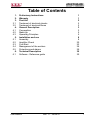
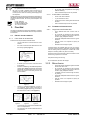
ATUPT10KHR1
User Manual
Volume 1
Manufactured by
Italy
File Name:
ATUPT10KHR1_ING_1.1.indd
Version:
1.1
Date:
09/08/2012
Revision History
Date
Version
12/03/2012 1.0
09/08/2012 1.1
Reason
First Version
Minor Upgrades
Editor
J. H. Berti
J. H. Berti
ATUPT10KHR1 - User Manual
Version 1.1
© Copyright 2012
R.V.R. Television
Via del Fonditore 2/2c - 40138 - Bologna (Italia)
Telephone: +39 051 6010506
Fax: +39 051 6011104
Email:
[email protected]
Web:
www.rvr.it
All rights reserved
Printed and bound in Italy. No part of this manual may be reproduced,
memorized or transmitted in any form or by any means, electronic
or mechanic, including photocopying, recording or by any information storage and retrieval system, without written permission of the
copyright owner.
Notification of intended purpose and limitations of product use
This product is a FM transmitter intended for FM audio broadcasting. It utilises
operating frequencies not harmonised in the intended countries of use.
The user must obtain a license before using the product in intended country of
use. Ensure respective country licensing requirements are complied with.
Limitations of use can apply in respect of operating freuency, transmitter power
and/or channel spacing.
Declaration of Conformity
Hereby, R.V.R. Elettronica SpA, declares that this FM transmitter is in
compliance with the essential requirements and other relevant provisions of
Directive 1999/5/EC.
ATUPT10KHR1
Table of Contents
1.
2.
3.
3.1
3.2
4.
4.1
4.2
4.3
5.
5.1 5.2 5.3
5.4
5.5
6.
6.1
Preliminary Instructions
Warranty
First Aid
Treatment of electrical shocks
Treatment of electrical Burns
General Description
Composition
Make-Up
Operating Principles
Installation and use
Assembly
Amplifier Check
First Start
Management of the exciters
Protections and alarms
Technical Description
Software - Reference guide User Manual
Rev. 1.1 - 09/08/12
1
1
2
2
2
3
3
5
5
8
8
20
23
26
29
30
30
ATUPT10KHR1
This page was intentionally left blank
ii
Rev. 1.1 - 09/08/12
User Manual
ATUPT10KHR1
IMPORTANT
The symbol of lightning inside a triangle placed on the product, evidences the operations for
which is necessary gave it full attention to avoid risk of electric shocks.
The symbol of exclamation mark inside a triangle placed on the product, informs the user
about the presence of instructions inside the manual that accompanies the equipment, important for the efficacy and the maintenance (repairs).
Operation of this equipment in a residential area may cause
radio interference, in which case the user may be required
to take adequate measures.
1. Preliminary Instructions
• General Warnings
The specifications and data contained herein are provided
for information only and are subject to changes without
prior notice. R.V.R. Television disclaims all warranties,
express or implied.While R.V.R. Television attempts to
provide accurate information, it cannot accept responsibility
or liability for any errors or inaccuracies in this manual,
including the products and the software described herein.
R.V.R. Television reserves the right to make changes to
equipment design and/or specifications and to this manual
at any time without prior notice.
This equipment should only be operated, installed and
maintained by “trained” or “qualified” personnel who are familiar
with risks involved in working on electric and electronic circuits.
“Trained” means personnel who have technical knowledge of
equipment operation and who are responsible for their own
safety and that of other unqualified personnel placed under
their supervision when working on the equipment.
“Qualified” means personnel who are trained in and
experienced with equipment operation and who are
responsible for their own safety and that of other unqualified
personnel placed under their supervision when working on
the equipment.
WARNING: Residual voltage may be present inside
the equipment even when the ON/OFF switch is set to
Off. Before servicing the equipment, disconnect the
power cord or switch off the main power panel and
make sure the safety earth connection is connected.
Some service situations may require inspecting the
equipment with live circuits. Only trained and qualified
personnel may work on the equipment live and shall be
assisted by a trained person who shall keep ready to
disconnect power supply at need.
R.V.R. Television shall not be liable for injury to persons or
damage to property resulting from improper use or operation
by trained/untrained and qualified/unqualified persons.
WARNING: The equipment is not water resistant.
Any water entering the enclosure might impair proper
operation. To prevent the risk of electrical shock or
fire, do not expose this equipment to rain, dripping or
moisture.
Please observe local codes and fire prevention rules when
installing and operating this equipment.
WARNING: This equipment contains exposed
live parts involving an electrical shock hazard. Always
disconnect power supply before removing any covers
or other parts of the equipment.
Ventilation slits and holes are provided to ensure reliable
operation and prevent overheating; do not obstruct or
cover these slits. Do not obstruct the ventilation slits under
any circumstances. The product must not be incorporated
in a rack unless adequate ventilation is provided or the
manufacturer’s instructions are followed closely.
WA R N I N G : T h i s e q u i p m e n t c a n r a d i a t e
radiofrequency energy and, if not installed in compliance
with manual instructions and applicable regulations,
may cause interference with radio communications.
WARNING: This equipment is fitted with earth
connections both in the power cord and for the chassis.
Make sure both are properly connected.
User Manual
• Notice concerning product intended purpose and use
limitations.
This product is a radio transmitter suitable for frequencymodulation audio radio broadcasting. Its operating
frequencies are not harmonised in designated user countries.
Before operating this equipment, user must
obtain a licence to use radio spectrum from the
competent authority in the designated user country.
Operating frequency, transmitter power and other
characteristics of the transmission system are subject to
restrictions as specified in the licence.
2. Warranty
La R.V.R. Television warrants this product to be free from
defects in workmanship and its proper operation subject to
the limitations set forth in the supplied Terms and Conditions.
Please read the Terms and Conditions carefully, as purchase
of the product or acceptance of the order acknowledgement
imply acceptance of the Terms and Conditions.
For the latest updated terms and conditions, please visit our web
site at WWW.RVR.IT. The web site may be modified, removed
or updated for any reason whatsoever without prior notice.
The warranty will become null and void in the event the
product enclosure is opened, the product is physically
damaged, is repaired by unauthorised persons or is used for
purposes other than its intended use, as well as in the event
of improper use, unauthorised changes or neglect. In the event a defect is found, follow this procedure:
1 Contact the seller or distributor who sold the equipment;
provide a description of the problem or malfunction for
the event a quick fix is available. Sellers and Distributors can provide the necessary
information to troubleshoot the most frequently encountered
problems. Normally, Sellers and Distributors can offer a
faster repair service than the Manufacturer would. Please
note that Sellers can pinpoint problems due to wrong
installation.
2 If your Seller cannot help you, contact R.V.R. Television
and describe the problem; if our staff deems it
appropriate, you will receive an authorisation to return
the equipment along with suitable instructions;
3 When you have received the authorisation, you may
return the unit. Pack the unit carefully before shipment;
use the original packaging whenever possible and seal
the package perfectly. The customer bears all risks of
loss (i.e., R.V.R. shall not be liable for loss or damage)
until the package reaches the R.V.R. factory. For this
reason, we recommend insuring the goods for their full
value. Returns must be sent on a C.I.F. basis (PREPAID)
to the address stated on the authorisation as specified
by the R.V.R. Service Manager.
Rev. 1.1 - 09/08/12
/ 42
ATUPT10KHR1
Units returned without a return authorisation may
be rejected and sent back to the sender.
4 Be sure to include a detailed report mentioning all
problems you have found and copy of your original
invoice (to show when the warranty period began) with
the shipment.
Please send spare and warranty replacement parts orders to
the address provided below. Make sure to specify equipment
model and serial number, as well as part description and
quantity.
3.1.2
R.V.R. Television
Via del Fonditore, 2/2c
40138 BOLOGNA ITALY
Tel. +39 051 6010506
3. First Aid
All personnel engaged in equipment installation, operation
and maintenance must be familiar with first aid procedures
and routines.
3.1
Electric shock treatment
3.1.1
If the victim is unconscious
Lay the victim down on his/her back on a firm
surface.
•
the neck and tilt the head backwards to free
Do not stop chest compressions while giving
artificial breathing.
•
Call for medical help as soon as possible.
If the victim is conscious
•
Cover victim with a blanket.
•
Try to reassure the victim.
•
Loosen the victim’s clothing and have him/her
lie down.
•
Call for medical help as soon as possible.
3.2
Treatment of electric burns
3.2.1
Large burns and broken skin
Follow the first aid procedures outlined below.
•
•
•
Cover affected area with a clean cloth or
linen.
•
Do not break any blisters that have formed;
remove any clothing or fabric that is stuck to
the skin; apply adequate ointment.
•
Administer adequate treatment for the type of
accident.
•
Get the victim to a hospital as quickly as
possible.
•
Elevate arms and legs if injured.
If medical help is not available within an hour, the victim is
conscious and is not retching, administer a solution of table
salt and baking soda (one teaspoon of table salt to half
teaspoon of baking soda every 250 ml of water).
the airway system (Figure 1).
Have the victim slowly drink half a glass of solution for four
times during a period of 15 minutes.
Stop at the first sign of retching.
Do not administer alcoholic beverages.
Figure 1
•
If needed, open the victim’s mouth and check
for breathing.
•
If there is no breathing, start artificial respiration
without delay (Figure 2) as follows: tilt the head
backwards, pinch the nostrils, seal your mouth
around the victim’s mouth and give four fast
rescue breaths.
3.2.2 Minor burns
•
Apply cold (not ice cold) strips of gauze or dress
wound with clean cloth.
•
Do not break any blisters that have formed;
remove any clothing or fabric that is stuck to
the skin; apply adequate ointment.
•
If needed, have the victim change into clean,
dry clothing.
•
Administer adequate treatment for the type of
accident.
•
Get the victim to a hospital as quickly as
possible.
•
Elevate arms and legs if injured.
Figure 2
•
/ 42
Check for heartbeat (Figure 3); if there is
no heartbeat, begin chest compressions
immediately (Figure 4) placing your hands in
the centre of the victim’s chest (Figure 5).
Figure 3
Figure 4
Figure 5
•
One rescuer: give 2 quick rescue breaths after
each 15 compressions.
•
Two rescuers: one rescue breath after each 5
compressions.
Rev. 1.1 - 09/08/12
User Manual
ATUPT10KHR1
4. General Description
The ATUPT10KHR1 is a trasmitter for TV broadcasting, manufactured by ,
manufactured by R.V.R. Elettronica S.p.A.. It is a fully solid-state apparatus of
modern design that uses LD-MOSFET as active components in the FM amplifying
modules
The ATUPT10KHR1 transmitter constitutes the end power section for TV
transmitters fitted with different possible configurations. A control system for the
exciters is built into the machine so that in order to have a system with redundant
exciters, all that needs to be done is to include two exciters in the transmitter such
as the STU05 exciters.
It is a fully solid-state apparatus of modern design that use MOSFET as active
components in the TV amplifying modules. This chapter briefly describes the
machine’s main features.
4.1 Composition
The ATUPT10KHR1 transmitter is made up of modules inserted in two 19” rack.
The main modules are as follows:
• 1 x 10 W TV exciters (STU05)
• 1 x 10 kW TV amplifier modules (ATVHA10K)
•
1 Control Unit
•
10 x 1.2 kW RF amplifier modules
•
2 Power supply unit carriages
•
1 Splitter/Input RF
•
1 Combiner/Output RF
• 1 Dummy Load (Unbalanced Unit)
Note: ATUPT10KHR1D transmitter is composed of 2 exciters.
User Manual
Rev. 1.1 - 09/08/12
/ 42
ATUPT10KHR1
Frontal View
The transmitter is supplied complete with all its parts, not really “modules”, essential
for its operation such as the pumps for dissipating the heat generated by the
machine inside the room and all the accessories for the electrical and RF wiring.
The transmitter is supplied with two TV exciters that it manages will be provided
and connected (a service exciter and a spare exciter).
/ 42
Rev. 1.1 - 09/08/12
User Manual
ATUPT10KHR1
4.2 Make-Up
Frequency range:
Nominal RF power:
Power supply voltage:
Exciting power:
Consumption:
Power factor:
Weight:
UHF IV&V band 470 to 862 MHz
10,000 WPS (Analog Mode)
400 Three-phase, 3F+N
About 6 W
About 20 kW (with red pattern)
> 0.95
500 kg (rack) – 20 kg (module) – 140 kg
(Power supply)
Additional important features of the ATUPT10KHR1 are as follows:
• The 1.2 kW amplifying modules are implemented by means of plug-in technology:
the individual modules may be removed for performing maintenance operations,
for instance, without having to turn off the transmitter. The transmitter keeps
working at reduced power even if the module has been removed. This operation
may be carried out without any risk of damaging the module itself, or the amplifier
as a whole, thanks to the control system and to the RF connectors, the power
supply and the purposely designed data-exchange. For further information refer
to the maintenance section.
• Each amplifying module is controlled by a microprocessor-based card that
checks and adjusts its operating mode. The resulting data are transmitted to
the control unit.
• The transmitter can work as usual even if the control unit is not present. In
fact, the control unit may be substituted temporarily with an electromechanical
interface by means of which the user may give the ON and OFF commands
to the machine. However, in this case all the numeric type information will be
missing and the power level remains the last one enabled before removing the
control unit.
4.3 Operating Principles
The ATUPT10KHR1 exciter essentially comprises three blocks:
• The power supply section
• The Splitter-Coupler section
• The RF amplifier section
• The Exciter section
The power supply section of the ATUPT10KHR1 transmitter is made up of two
three-phase transformers, each one associated with a rectifier circuit for generating
the non-stabilized voltage of 80V that supplies the RF modules. The transformers
and the rectifier circuits are mounted on removable carriages together with power
inductors that help achieve a power factor of about 0,96.
The power supply section is controlled by a microprocessor-based card installed
in the rack.
User Manual
Rev. 1.1 - 09/08/12
/ 42
ATUPT10KHR1
The Splitter-Coupler section performs all the treatment of the RF signal except for
the power amplification.
Block Diagram of Trasmitter
The RF signals generated by two exciters (in the redundant configuration) are first
attenuated by 3 dB to improve the uncoupling among the stages and then connected
to a coaxial relay commanded by the control unit. One of the two signals is closed
on a dummy load built into the machine whereas the other signal is connected to
the input splitter. The power of both signals is measured by specific directional
couplers.
The RF signal of the selected exciter is divided into ten branches (five branch for
each rack), each of which is passed to the input of an amplifying module.
The ten RF amplifiers branches are recombined by the coupler at the output of the
amplifying modules. The overall amplified RF signal is filtered by a band-pass filter
for eliminating the harmonics and is therefore available at the output connector.
The Splitter-Coupler section is controlled by a microprocessor-based card, which
makes the values detected at the various measuring points available for the user
and for the diagnostics functions.
/ 42
Rev. 1.1 - 09/08/12
User Manual
ATUPT10KHR1
The machine contains 10 R.F. amplifier modules each of which is capable of
supplying a maximum of 1.2 kW RF. Each module includes a switching mode
power supply unit that regulates and stabilizes the power supply voltage supplied
by the power supply section.
Each amplifying module contains a ten stage with gain that varies according to the
LD-MOSFET MRF373. The RF signal amplified by the driver is then separated into
four branches, amplified by four modules based on LD-MOSFET BLF888.
Each RF amplifying module is controlled by a microprocessor-based card,
connected to the other microprocessor-based cards of the machine by means of
a RS485 type bus.
User Manual
Rev. 1.1 - 09/08/12
/ 42
ATUPT10KHR1
5. Installation and use
This chapter contains the basic instructions for installing and using the
ATUPT10KHR1 transmitter. If necessary, more in-depth information about the
operating principles may be traced in the next chapters.
5.1 Assembly
For practical reasons and for transport safety, the machine is usually supplied
disassembled to the customer. The assembly procedure is rather simple and can
be carried out by any qualified technician.
Note: In order to avoid the risk of damaging the machine and/or of injuring the
operators, it is advisable to closely adhere to the instructions provided below.
always respect all the safety regulations and standards in force.
Identify the machine components:
• The racks (various components are assembled, such as the coupler, the splitter,
the control unit, the amplifiers and exciters)
Check that all the components are in perfect working order. Should there be any
kind of problem, for instance if there is any damage caused by the transport of the
components, read the instructions associated with the Warranty at the beginning
of this manual.
1 Combine the two bulk rack between them near the location where the transmitter
will work.
/ 42
Rev. 1.1 - 09/08/12
User Manual
ATUPT10KHR1
Fix the racks with the screws (x4) positioned 2 in front side and 2 in rear side
in conjunction, indicated by LOCK labels.
2 Install the racks in the location where the transmitter will work. The transmitter is cooled by liquid cooling and the liquid outlet is on the machine’s roof.
Once removed the packaging protections, place it in the position you want it to run.
Fix on the floor with the screws (x4) positioned in the corners at the base of
the racks.
User Manual
Rev. 1.1 - 09/08/12
/ 42
ATUPT10KHR1
3 Perform the connection of the low power supply by connecting the red and
black cables of rack 1 to that of rack 2.
4 Connect the machine’s interconnection cable.
Route the cable (13-pole type), from rack 2 to rack 1, through the internal side
and fix the conductors to the terminals of the master switch.
10 / 42
Danger: connect the conductors using the same numbering placed on the wire
Rev. 1.1 - 09/08/12
User Manual
ATUPT10KHR1
5 Connect the machine’s main power supply cable. Route the cable (5-pole
type) through the raceway on the machine’s roof and fix the conductors to the
terminals of the master switch.
External view (Power supply cable)
It is recommended not to turn on the machine without first have
connected the RF exit to the antenna or to the dummy load!
The ATUPT10KHR1 requires a three power supply 3F (black, brown and grey)
+ N (blue) + GND (green yellow) able to give threephase 380 or threephase
220, 50 or 60 Hz for phase (otherwise it could seriously damage). Keep this
requirement in mind in connecting to the personal distribution board.
Interrnal view (Power supply cable)
User Manual
Rev. 1.1 - 09/08/12
11 / 42
ATUPT10KHR1
Danger: The connection of the machine to the electric alimentation is performed
fixing to a 5 poles cable with bare terminals to a terminal block. Making sure without
any possibility of error that the cable is not under tension while working on it.
7 Perform the connection between DB9 (CN1 SECOND SPLITTER and CN2KDI)
from rack 1 to rack 2 through the internal side.
8 Perform the interconnetion between BUS INT from rack 1 to rack 2 through the
internal side.
9 Perform the RF connetion between rack 1 and rack 2 through the internal side
by connect the SPLITTER IN1-B 29 cable of rack1 to 0° input of rack 2.
12 / 42
Rev. 1.1 - 09/08/12
User Manual
ATUPT10KHR1
10Connect the hybrid coupler between the RF output of rack 1 (PWR OUT RACK
1) and the RF output of rack 2 (PWR OUT RACK 2) located on relative roofs,
remembering to fix the screws. Connect using the same name on the labels,
for a proper installation.
11 Connect the rejected power-line between the first output of hybrid coupler
(REJECTED POWER-LINE “A”) and dummy load input (TO DUMMY LOAD
INPUT “G”) placed inside the rack 2, remembering you must tighten the screws
to fixing.
User Manual
Rev. 1.1 - 09/08/12
13 / 42
ATUPT10KHR1
In case that the rejected power-line was supplied dismantled, for a correct
assembly, use the same name on the labels to combine the several parts.
12Connect the directional coupler (IN DCPLR “A”) on the second output of hybrid
coupler, remembering that you must tighten the screws to fixing.
14 / 42
Rev. 1.1 - 09/08/12
User Manual
ATUPT10KHR1
13Perform the connection of the forward power control by connecting the TX FWD
OUT 11 cable of rack 1 to FWD of directional coupler.
Perform the connection of the reflected power control by connecting the
TX RFL OUT 13 cable of rack 1 to RFL of directional coupler.
Perform the connection of the RF monitor control by connecting the RF
MONITOR 23 cable of rack 1 to RF MONITOR of directional coupler.
14Insert the first amplifying module into the RF modules compartment.
User Manual
Rev. 1.1 - 09/08/12
15 / 42
ATUPT10KHR1
The modules have a groove at the top and one at the bottom: insert the
modules so that the guides in the compartment fit into these grooves.
Slide the module until the two fixing screws fit into their seats. Then
tighten the fixing screws at the same time so that the module inserts
into its compartment remaining parallel until it is perfectly in place.
Repeat the operation with the other four RF modules.
15Insert the first transformer carriage into the left-hand side of the specific
compartment of rack 1. The carriage is mounted on three wheels (two are fixed
on the front side and one pivoting rear wheel) to facilitate this operation. Move
the carriage toward the left-hand wall of the rack and then move it forward until
the connectors at the back are perfectly inserted into their seats.
16 / 42
Note: The power supply unit carriage is very heavy and its barycenter is high,
therefore be careful when handling it to avoid tipping it over.
Insert the second power supply unit carriage as you did with the first one.
Position the stop bar of the power supply unit carriages.
Make the necessary connections of the power supply unit carriages :
•
•
Power supply connector
Data connectors
Rev. 1.1 - 09/08/12
User Manual
ATUPT10KHR1
Connect the machine’s main power supply cable. Route the cable (5-pole
type) through the raceway on the machine’s roof and fix the conductors to
the terminals of the master switch. The last operation is usually performed by
removing the knob and the cover of the isolating switch.
Note: The connection of the machine to the electric alimentation is performed fixing
to a 5 poles cable with bare terminals to a terminal block. Making sure without
any possibility of error that the cable is not under tension while working on it. It is
reccomended not to turn on the machine without first have connected the RF exit
to the antenna or to the dummy load!
16Identify the dummy load and, and as a first step, open the red valve on the
dummy load by removing the screw on it.
Insert the dummy load in the rack 2 and secure through 4 screws, being careful
to have the RF output facing the rear of the transmitter.
Connect the power cord to the rack 2.
User Manual
Rev. 1.1 - 09/08/12
17 / 42
ATUPT10KHR1
17Reposition the roof panels, the protection panels of the RF modules, the
protection panel of dummy load and of the transformer/rectifier carriages.
18Perform the connection of the unbalanced power ouput control by connecting
the EXT. UNBAL PWR-OUT cable to UNBAL POWER OUT of rigid line.
The other side of EXT. UNBAL PWR-OUT cable must be connected with UNBAL
PWR INPUT (DB9 connector) placed on the top, on the plate connectors.
19Always on the top, on the plate connectors, put the VDE bridge or the UPS
(opt.) and turn it on, otherwise the control logic will not work.
.
20Connect the rigid line (IN RIGID LINE “A”) to the directional coupler output (TO
IN RIGID LINE “A”), remembering that you must tighten the screws to fixing.
18 / 42
Rev. 1.1 - 09/08/12
User Manual
ATUPT10KHR1
The other side of the rigid line (TO FILTER INPUT “F”) must be connected
to the filter input on the roof of rack 2 (FILTER INPUT “F”), remembering that
you must tighten the screws to fixing.
In case that the rigid line was supplied dismantled, for a correct assembly, use
the same name on the labels to combine the several parts.
19Connect the antenna cable to FILTER OUPUT (TO ANTENNA).
20Perfom all connections video and audio from its source to the transmitter.
.
• Connect AUDIO INPUT “EXCITER 1” - MONO OUT “XLR” cable between
AUDIO IN 1 of STU05 and MONO OUT of NICAM encoder.
• Connect IF OUTPUT MCX - NICAM INPUT BNC cable between IF OUT (VISION
MODULATOR) of STU05 and NICAM IN of NICAM encoder.
• Connect IF INPUT MCX - NICAM OUTPUT BNC cable between IF IN (IF
PRECORRETTOR) of STU05 and NICAM OUT of NICAM encoder.
Note: The video and audio connectors are not in parallel but directly connect to
the exciters.
21Now you may perform the preliminary checks on the transmitter and start it
up.
User Manual
Rev. 1.1 - 09/08/12
19 / 42
ATUPT10KHR1
5.2 Amplifier Check
The operator controls and checks the status of the ATUPT10KHR1 by means of
the control unit. Two control groups are present on this unit:
• LCD and scroll buttons
• Buttons, selector switches and LEDs
• Analogue instrument and rotary selector switch
Default Screen
20 / 42
Rev. 1.1 - 09/08/12
User Manual
ATUPT10KHR1
Menu select Screen
5.2.1 LCD and scrolls buttons
The operator uses the control software of the transmitter by means of a series of
menus that are displayed on the LCD. Four specific keys are provided for scrolling
through the menus, performing the settings and giving the commands:
Function
OK
ESC
Description
Click this button to access a sub-menu,
to enter the editing mode or to confirm a
modified value.
Click this button to exit from a menu or to
cancel the modification of a value.
Click this button to scroll inside a menu (to
the right or down) or to reduce the value of a
parameter being modified.
Click this button to scroll inside a menu (to
the left or up) or to increase the value of a
parameter being modified.
When the operator is not using the various buttons to navigate, the LCD displays
the preset screenful that shows the overall status of the machine’s modules. The
control unit acquires, every second, the status of the other modules by means of
a COM serial bus. The activity at the bus is signalled by the “BUS INT” LEDs on
the unit’s panel.
As indicated on the preset screenful, push the ESC button to access the screenful
for selecting the menus.
On reaching the selection screenful, move the cursor (full rectangle) using the
arrow keys to display the concerned line. Then click OK to access the associated
menu. Select the “General Status” menu to return to the preset screenful.
5.2.2 Buttons, selector switches and LEDs
The typical machine-control operations are performed using the buttons of the
control unit’s panel. Specific LEDs correspond to each button and selector switch
for indicating the machine’s status.
User Manual
Rev. 1.1 - 09/08/12
21 / 42
ATUPT10KHR1
The functions performed by the controls are as follows:
Function
OFF
STDBY
ON
LOC/REM
ALARM RESET
NOMINAL POWER
POWER LOWER
EXCITER CHANGEOVER
LEDs (Wait, Warning, Fault)
22 / 42
Description
Button for turning off the machine. A LED
signals that the machine is OFF. In this
status, the exciters and the fan are off and
the RF amplifying modules are not powered.
Button for setting the machine in standby. In
Not Used.
Button for turning on the transmitter. The RF
power supply is activated.
Selector switch for setting the transmitter
in remote or local mode. In local mode the
buttons and the controls via the menus are
active. In remote mode the buttons and the
controls via the menus are inhibited and
the commands may be given only remotely
via the parallel interface or via the remote
control software.
Button for zeroing the FAULT or WARNING
alarms.
Not Used.
Not Used.
Use this button to set the changeover
system in manual or automatic mode.
The signaling LED turns on when the
manual mode is selected. On performing a
changeover, the exciter connected to the
amplifier is deviated toward the internal
dummy load and vice-versa. The operator
must use the exciters menu to perform the
changeover in manual mode.
Other signaling LEDs are connected to
the alarm states and to the serial data
transmissions that take place among the
microprocessorbased cards. The function
of these LEDs is described further on in this
manual.
Rev. 1.1 - 09/08/12
User Manual
ATUPT10KHR1
5.2.3 Analogue instruments
The control unit of ATUPT10KHR1 contains an analog meter with a rotating selector
that are useful for an immediate display of the following parameters:
Function
FWD PWR RFL PWR UNBAL PWR EXC1 PWR EXC2 EXT FWD PWR
EXT RFL FWD
EXT UNBAL Description
Transmitter direct power
Transmitter reflected power
Transmitter unbalancing power
Power supplied by the exciter currently
connected to the amplifier. This value is
measured by the machine in the splitter
section
Power supplied by the exciter currently
connected to the internal load. This value
is measured by the amplifier in the splitter
section
Direct power of an external combiner.
Reflected power of an external combiner.
Unbalancing power of an external combiner.
These three values are used when the
transmitter is connected to a 1+1 system.
The SET outputs may also be connected to
these quantities.
5.3 First Start
This section describes the procedure for powering-on the machine the first time. For
simplicity’s sake, the automatic control capacities of the exciters are temporarily disabled.
Refer to chapter 5.4 that provides the instructions for turning on the ATUPT10KHR1
in the various cases.
5.3.1 Preliminary operation
Before activating this piece of equipment, the necessary connections must be
performed, and in particular:
• Power supply
• Modulating signals (TV, Audio or MPX, RDS...)
• RF load (antenna feeder or dummy load)
About to the connections of the power supply and the modulating signals, please
refer to chapter 5.1.
The machine’s RF output is the “EIA 1 5/8” flanged type and is accessed on the
roof of the ATUPT10KHR1 . If a dummy load capable of dissipating the RF power
generated by the transmitter is available, it is advisable to run the first tests by
connecting to it rather than to the transmission antenna.
User Manual
Rev. 1.1 - 09/08/12
23 / 42
ATUPT10KHR1
5.3.2 Power-on
When powering-on the transmitter the first time, perform the operations outlined
in the table below.
The “Result” column indicates the immediate results of the operations performed
plus a few indications that confirm that the machine is working efficiently.
Should any inconsistencies occur as compared to these indications, interrupt
the procedure and identify the reason for the malfunction before resuming the
procedure.
Operation
Result
Close the “Transformer Breaker” isolating switches
The power supply unit carriages are
powered
Turn the “Mains” switch
The whole transmitter is powered. The
machine is activated in the same status it
was in when it was turned off the last time
Press the OFF key of the control unit
RF emission by the transmitter is inhibited;
the exciters are off; the RF amplifier modules
are off
Press the EXCITER CHANGEOVER key of the control unit
The automatic management for the exciters
changeover is disabled. The MANUAL LED
must be on (otherwise press the key again)
Set the parameters of the control unit
This procedure is described in chapter
5.3.3 on in this manual. The control unit
communicates the nominal power and
reduced power values to the RF modules. It
also handles the coaxial relays so that the
on air exciter is the desired one and sets the
exciter to ON mode
Set the exciters
Adhere to the instructions of the exciters
used for setting the required work frequency
on the exciters. Regulate the output power
of the exciters to 20 W.
Press NOMINAL POWER and ON
The current exciter is activated (the interlock
is released from the exciter) and its power
emission is enabled. The power emitted
by the ATUPT10KHR1 amplifier increases
gradually until it attains the level that had
been set previously as “Nominal power”.
Check the emitted power level by means
of the analog instrument with the selector
switched to FWD PWR position.
When the transmitter is on and works at its nominal power, the whole series of
“accessory” checks and settings deemed necessary may be carried out before
starting up the apparatus.
24 / 42
Rev. 1.1 - 09/08/12
User Manual
ATUPT10KHR1
5.3.3 Control unit settings
The settings of the control unit that are required for starting up the machine,
mentioned in the powering-on procedure, are the following:
1 Setting of the power levels
2 Setting of the on air exciter
Before performing the first operation, click the ESC button. The display shows the
screenful for selecting the menus. Click the arrow keys until the cursor highlights
the line associated with the Setting menu. Click OK: the software will show the
associated screenful on the display.
Menu Settings Screen
Before performing the first operation, click the ESC button. The display shows the
screenful for selecting the menus. Click the arrow keys until the cursor highlights
the line associated with the Setting menu. Click OK: the software will show the
associated screenful on the display.
On having accessed the Settings menu, use the arrow keys to select the nominal
power line (Pwr. Out) and click OK. Use the arrow keys to decrease or increase
the indicated percentage value up to the required level. Click OK again to set this
value. Repeat the operation for the line associated with the reduced power level
(Pwr. Lower).
The new power level is transmitted to the combiner module and then stored in
EEPROM only when the ESC button is clicked.
When inside this menu, it is advisable to check the date and time lines and update
them if necessary. Note: the date and time are used only for marking the events
in the alarms register.
The date and time do not need to be updated in the transmitter in order for it to
work efficiently.
On having completed these settings, click ESC to return to the selection
screenful.
User Manual
Rev. 1.1 - 09/08/12
25 / 42
ATUPT10KHR1
In order to set the on air exciter, select the Exciters menu. Take into consideration
the On Air Exciter line: the number to the right indicates the exciter being used.
To change it simply highlight the line and click OK.
Menu Exciters Screen
The exchange of the exciters is assisted from the software, that is when the
commutation is carried out, the interlock comes systematized in the correct way
independently from like they were. The interlock could be modified also manually
in case of necessity.
5.4 Management of the exciters
This chapter describes the ways in which the microprocessor controls the amplifier
and how the user may interact with the software.
The control unit can perform the automatic changeover between exciters if one
malfunctions. The Manual LED on the panel indicates, when it is lighted up, that
the automatic changeover function is disabled. In order to enable it, click the
EXCITER CHANGEOVER button and check that the LED turns off. In operation of
the ATUPT10KHR1 automatism state, the behavior of the machine will be different.
In this chapter are described the different cases.
In function of the state of the ATUPT10KHR1 automatism, the behaviour of the
machine will be various. In this chapter are described the different cases.
5.4.1 Start-up from power-on with exciters in manual mode
When powering on the machine with the exciters in manual mode, the apparatus
does not perform any check, both mute RF signals are active and the changeover
relay remains in standby status. Use the exciters menu to activate an exciter.
This is why, if the transmitter is left in manual mode, any momentary power
failure will cause the transmitter to be inactive when turned on again. Therefore
it is advisable to leave the ATUPT10KHR1 in automatic mode when you are not
performing maintenance operations.
26 / 42
Rev. 1.1 - 09/08/12
User Manual
5.4.2 From OFF to ON with exciters in manual
ATUPT10KHR1
When switching from OFF (or STDBY) to ON with the exciters in manual mode,
the apparatus does not perform any check and the exciter that is currently set to
on air is the one that is aired.
If the mains signal is not OK, the exciters turn off automatically.
If the maximum drive power is exceeded during operations (> 35W), the
ATUPT10KHR1 is set to fault status and power supply is cut to the exciters.A
message in the alarms menu signals this fault.
When the apparatus is set to STDBY, the mute RF signals of the exciters are not
activated and may be modified by the operator.
When the apparatus is set to EXT INT or AUX INT, the mute RF signals of the
exciters are not activated and may be modified by the operator.
5.4.3 Automatic changeover
When the ATUPT10KHR1 is in the exciter automatic changeover mode, the power
emitted by the on air exciter is checked constantly. If at any time the on air exciter
is no longer good (i.e. power drops to below the preset level), the apparatus is kept
operational whereas the exciter connected to the internal Dummy Load turns on.
If the latter one is good (i.e. it is capable of supplying the required power), then
the two exciters are changed over. Instead if the alternative exciter is not good, no
changeover takes place, the control unit commands the mute RF of the exciter to
Dummy Load, it waits 120 s. and repeats the attempt. This procedure is repeated
indefinitely until one of the two exciters is considered to be good.
During the whole length of time during which there is no good exciter,
theATUPT10KHR1 keeps the WAIT LED on for signalling this status.
Each exciter is fitted with its own mute RF. On being commanded, the piloting
signal must return to zero within 3 seconds at the most. If this does not occur, the
fault is recorded by an error message that is entered in the alarms menu.
If the mains signal is not OK, the exciters turn off automatically. If the piloting power
exceeds the limit during operations, the ATUPT10KHR1 is set to the FAULT status
and the power supply of the exciters is turned off. A message in the alarms menu
signals the fault. Keep in mind that the operator’s intervention is required to exit
from the FAULT status.
If the MAINS signal coming from the bus is not OK, the exciters are all turned off.
As soon as the MAINS signal is regular again, the evaluation cycle of the exciters
begins.
When the apparatus is set to STDBY, the mute RF signals of the exciters are
activated and as such both exciters are inhibited. If the ON key is pressed, the
system re-evaluates both exciters in the same manner as in the procedure from
OFF to ON.
User Manual
Rev. 1.1 - 09/08/12
27 / 42
ATUPT10KHR1
When the apparatus is set to EXT INT or AUX INT, the mute RF signals of the
exciters are activated and therefore both exciters are inhibited. When the external
interlocks are released, the system re-evaluates both exciters as during the phase
from OFF to ON.
5.4.4 Phase from ON to OFF
When the apparatus is set to OFF status and you press the ON button, the power
supply of the exciters is activated and the logic starts to evaluate the exciters.
During the evaluation phase, the WAIT LED stays ON.
When the apparatus is turned OFF, it memorizes the exciter on air. Consequently
when the machine restarts it can attempt to restore the previous conditions. On
the machine restarting, if the exciter that is to be aired does not attain the preset
power level whereas the spare one is operational, the apparatus performs the
changeover when the evaluation time (120 s.) expires.
On the machine restarting, if both exciters do not attain the preset power level,
the apparatus airs the one that had been present when the machine was turned
off, after the evaluation time has expired.
5.4.5 Start-up with exciters in automatic mode
The sequence run by the ATUPT10KHR1, when the power supply is activated
while it is already in ON status and the exciters are in automatic mode, is identical
to the one run for switching from OFF to ON. The only difference is that a screenful
displays the countdown for determining the fault of the exciters. During this phase
the manual/automatic button is inhibited and in order to set the exciters to manual
mode you must press the OFF button of the apparatus.
5.4.6 Start-up with exciters in automatic mode
The control unit of the ATUPT10KHR1 can manage a fault signal, for each
exciter, which normally has an “Audio Alarm” meaning. The control software of the
ATUPT10KHR1 does not intervene in triggering these signals since they must be
checked by the exciters (or by any other connected devices).
The Audio Alarm signals are made up of two inputs for the logical signals on the
parallel interface and on the “mute RF” command connector of the exciters.
The control unit manages these signals just like it manages the power good
signals:
• Each “Audio alarm” signal is associated with its own exciter
• If the audio signal, associated with the exciter that is currently on air, enters an
alarm status, the ATUPT10KHR1 waits for the time configured in the exciter
menu before it attempts the restoring operation
28 / 42
Rev. 1.1 - 09/08/12
User Manual
ATUPT10KHR1
• If the audio of the aired exciter is still in alarm status on the elapsing of the
aforesaid time interval, the control unit checks if the audio of the exciter on the
dummy load is regular. In this case the changeover between the exciters is
performed.
Observe the following differences as compared to the case in which power is
missing:
• The management of the “Audio alarm” signals is not active during the startup phase and during the switching phase from OFF to ON, but only when the
exciters are working in automatic.
• In the standard configuration, the aforesaid sequence continues until the audio
signal associated with one of the exciters becomes regular again. In the “N+1”
configuration, the switching attempt is performed only twice, after which the
ATUPT10KHR1 enters the fault status.
• An Audio Alarm output is provided on the parallel interface: this signal is activated
(with no delays) when the audio of the exciter that is currently on air is in alarm
status.
5.5 Protections and alarms
The ATUPT10KHR1 contains a complete protection and alarms system, both at
the individual modules level and at the control unit level.
The modules are fitted with a micro-processor-based system that manages any
malfunctions locally. The associated information is communicated to the control
unit for displaying and storing the events and for the centralized management of
the events that require it.
Certain LEDs of the ATUPT10KHR1 panel are dedicated to the management of
the alarms:
LED
WARNING
FAULT
WAIT
Description
This LED indicates a warning (something is
not correctly working, but the amplifier is still
working)
This LED indicates a fault (the transmitter
is shut off, the operator’s intervention is
required)
This LED indicates the wait status (the
transmitter is temporarily off, it will be
restarted as soon as the reason that keeps
it from working will be removed, or after
a fixed amount of time depending on the
reason of the intervention of the protection
system)
The ALARM RESET button is used for resetting the alarms and restarting the
machine.
User Manual
Rev. 1.1 - 09/08/12
29 / 42
ATUPT10KHR1
6. Technical Description
6.1 Software - Reference guide
This chapter gives a point to point description of the screens composing the
software of the ATUPT10KHR1.
Since the management software is able to control up to 10 modules, some of
the menus configurate themselves for the number of modules. For example, in a
ATUPT10KHR1 the menu Overall Status has four “RF Unit” lines, so only four of
them will be shown.
6.1.1 Overall Status Menu
This is the default menu appearing when the user switches the unit on.
This menu includes only indications, therefore the user cannot insert any input in
its different lines.
Menu Line
Timer
Control Unit
Power Supply
R.F. Combiner
R.F. Unit - N
Hours
Description
Not Used.
Status of the control unit (Off or On) and
indication of the exciter actually connected
to the amplifier (Exct.1 or Exct.2)
Status of the power-supply cart (Off or On)
Status of the RF combiner (Off or On)
Status of the Rf power amplifier number N
(Off or On)
Timer counting the hours of operation
of the transmitter. For example, this
indication is useful in order to define when a
maintenance operation can be made
From the predefined menu, by pressing the Esc key as indicated on the last line,
you can shift to the exchange screen from which you can have access to all the
other menus of the unit.
Menu Overall Status Screen
30 / 42
Rev. 1.1 - 09/08/12
User Manual
ATUPT10KHR1
6.1.2 Select Menu
This is the exchange menu from which you can select the different sub-menus
that compose the software.
In order to enter a sub-menu, select the correspondent line with the arrow buttons
and press Enter.
Menu Line
General Status
Power Supply
R.F. Combiner
R.F. Units
Alarms
Service
Settings
Exciters
Info
Release
Modem
Description
General status of the ATUPT10KHR1
Status of the power-supply cart
Status of the RF combiner
Status of the RF power amplifiers
Summary of the occured alarms
Service menu for the switching on/off of the
modules
Not Used.
Parameters of the exciters (i.e. output
power, on air exciter)
Information concerning the configuration of
the ATUPT10KHR1
Information concerning the hardware and
software versions of the modules composing
the unit
Settings related to the optional telemetry
system
To return to the predefined menu, select General Status and press OK.
Menu Select Screen
User Manual
Rev. 1.1 - 09/08/12
31 / 42
ATUPT10KHR1
6.1.3 Control Unit Menu
Informative menu on the inputs and the outputs of the control unit of the
machine.
Menu Line
Ext Intl
Aux Intl
Exc1 A.Audio
Exc2 A.Audio
Reserve 1
Reserve 2
Reserve 3
Reserve 4
Relay Exc
Exc 1 Mute
Exc 2 Mute
Audio Alarm
Exc’s Mains
Stand_by (In)
Stand_by (Out)
Total Eff
Description
Input status “external interlock” (JP4/4
parallel interface)
Input status “auxiliary interlock” (JP4/5)
Input status “audio alarm exciter 1” (JP4/8)
Input status “audio alarm exciter 2” (JP4/9)
Input status “Reserve 1” (JP8/2 parallel
interface)
Input status “Reserve 2” (JP8/3)
Input status “Reserve 3” (JP8/4)
Input status “Reserve 4” (JP8/5)
Exciters exchange relay status (Off = exciter
1 on air)
Exciter 1 interlock status (Off = RF power
enabled)
Exciter 2 interlock status (Off = RF power
enabled)
Output Audio Alarm status (JP47/1)
Exciters power supply status (On = power
supply enabled)
“Stand by” input line status
“Stand by” output line status from the control
unit
Total efficiency of the machine
Menu Control Unit Screen
32 / 42
Rev. 1.1 - 09/08/12
User Manual
ATUPT10KHR1
6.1.4 Power Supply Menu
Information menu showing the status of the Power Supply / Rectifier carriage.
Menu Line
Bus Bar
Room T.
Safety
Mains
Trafo-1T
Fuse-1
Trafo2-2T
Fuse-2
C.B. Blower
Supply-1
Supply-2
Blower
Description
Output voltage from the rectifier on the
common 80V dc supply bus.
Temperature of the air at the input of the unit
Status of the safety arrest button. On
indicates the functioning is enabled, Off
means the unit was arrested through the
button
Status of the main voltage supply. On
indicates that the voltage is within the
functioning range of the unit and that the
phase sequence is correct
Status of the AC fuses AC low voltage bus
bar rectifier and interblock of module 1
Status of the AC fuses AC low voltage bus
bar rectifier and interblock of module 1
Stesso significato di Trafo-1T. Quando il
carrello alimentatore/rettificatore 2 non è
installato, viene indicato ===.
Same function as Temp.1. When the supply/
rectifier module 2 is not installed, === is
indicated
Status of the magnetothermical “motor save”
interruptor of the circuit breaker blower.
Control contactor of module 1
Control contactor of module 2
Control contactor of the power of the blower
Power Supply Screen
User Manual
Rev. 1.1 - 09/08/12
33 / 42
ATUPT10KHR1
6.1.5 R.F. Combiner Menu
This menu contains the information related to the RF part of the complete
transmitter. Here the user will find the most interesting parameters, like the overall
emitted RF power and the reflected power.
Menu Line
Fwd
Rfl
Unbal
Rej.lT
Exhaust
S.W.R.
(External) Fwd
(External) Rfl
(External) Unbal
Main Exc
Stdby Exc
Temp
RF-Enb
Aux Fan
SET1
SET2
SET3
SET4
Description
Overall emitted RF power of the transmitter
Reflected RF power of the transmitter
Unbalancement RF power: sum of the power
dissipated on the internal resistors due to
unbalanecement in the RF modules
Temperature of the load resistors dissipating
the unbalancement power
Temperature of the exhaust air (top of the
transmitter)
Standing Wave Ratio, calculated by the
Control Unit on the basis of the measured
forward and reflected power
Forward power of an external transmitter
(when configured for this function)
Reflected power of an external transmitter
(when configured for this function)
Unbalancement power of an external
transmitter (when configured for this
function)
Output power of the exciter currently on air
(the one connected to the input of the RF
modules)
Output power of the exciter currently on the
internal dummy load
Status of the temperature alarm (sensor
included in the combiner)
RF output enable: “On” means that the RF
combiner unit is giving its permission for the
regular operation of the transmitter
Switch for an auxiliary fan (not used in the
current configurations)
Status of the output “SET1”. See the
Settings Menu
Status of the output “SET2”
Status of the output “SET3”
Status of the output “SET4”
Menu R.F. Combiner Screen
34 / 42
Rev. 1.1 - 09/08/12
User Manual
ATUPT10KHR1
6.1.6 R.F. Units Menu
Information menu showing the status of the RF power amplifier modules. It is
composed of 10 screens, one for each module, that can be scrolled using the
arrow buttons.
Menu Line
Fwd
Rfl
Input
V.P.A.
Driver
MOS N
I. Tot
Eff
Temp
Fuse
Unit. Intl
RF enb.
Description
Measurement of the forward power of the
amplifier module
Measurement of the forward power of the
amplifier module
Measurement of the driving power at the
input of the amplifier module
Measurement supply voltage of the module
(generated from the switching power supply
included in each module)
Measurement of the current absorbed by the
preamplifier stage
Measurement of the current absorbed by the
MOS N amplifier module (each RF module
contains 4 MOS modules)
Measurement of the total current absorbed
by the RF module
Efficiency of the amplifier module, as a result
of the ratio between the electrical power
absorbed and the RF output power
Temperature alarm, Ok or Ko
Status of the fuse of the RF module: Ok or
Ko
State of the RF module interlock microswitch
Enabled of power distribution from part of
the module
Menu R.F. Units Screen
User Manual
Rev. 1.1 - 09/08/12
35 / 42
ATUPT10KHR1
6.1.7 Alarms Menu
This screen describes all the registered events which are relevant to determine
the probable causes of any dysfunction. The screen is composed of a variable
number of pages (up to 10) in function of the number of events occurred. The last
events in chronological order are shown in the first page and so on. To shift to the
different pages, use the arrow buttons.
Menu Line
Unit
Err
Time
Date
It is not possible to cancel the alarms in the display
Description
Module of the system which generated the
failure
Type of failure and description. The type
of failure can be W (Wait) - the unit goes
in stand-by until the cause of the failure is
removed, R (Retry) - the unit is locked for
a predefined time lag after which a reset
attempt is launched, or F (Fault) - the unit
is completely locked and requires the
intervention of the user in order to remove
the cause of the failure.
Time (hrs and minutes) at which the failure
occured
Date at which the failure occured
Menu Alarms Screen
36 / 42
Rev. 1.1 - 09/08/12
User Manual
ATUPT10KHR1
6.1.8 Service Menu
This menu is normally used during the maintenance operations. When this screen
is visualized, the Control Unit checks the status of the modules of the unit more
frequently in order to have a visualization of the different parameters as fast as
possible. When this menu is entered, all the secondary functions are interrupted,
therefore a possible alarm may not be visualized and registered immediately;
when exiting this menu all the alarms which were temporarily put in “stand-by”
are registered. If the user sets some modules in OFF modality, these will be
automatically reactivated when exiting the menu. This menu is deactivated after
60 minutes if no key is selected.
Menu Line
Fwd
Unb
RF UnitN - On
Fwd
Rfl
Description
Forward power globally emitted by the
amplifier
Unbalancing power dissipated in the
combiner module.
Fields used to switch ON and OFF the
amplifier modules. Before the removal of
an amplifier module for its replacement or
maintenance switch it off with the help of the
corresponding line.
Forward power generated by the RF module
Reflect power from the RF module
Service Screen
User Manual
Rev. 1.1 - 09/08/12
37 / 42
ATUPT10KHR1
6.1.9 Settings Menu
This menu is used for the settings of the unit. It is therefore the menu which is
used more often apart from the possible maintenance operations.
Menu Line
Nominal Power
Description
Setting of the level of nominal power,
expressed as a percentage of the maximum
power level. This is the level that the
ATUPT10KHR1 must reach when the Power
Nominal button is pressed, except in case of
dysfunction.
Pwr. Lower
Setting of the reduced power level,
expressed as a percentage of the maximum
power level. This is the level that the
ATUPT10KHR1 must reach when the Power
Lower button is pressed, except in case of
dysfunction.
SET1
Level (Limit) at which the “Power Good”
SET1 is launched. This level is expressed as
a percentage of the full-scale to which SET1
is connected, indicated in the column Assign
SET2
See SET1
SET3
See SET1
SET4
See SET1
Exct. Wait time
Delay before assuming the on air exciter is
faulty
Talk Address
Address of the unit in the RS485 network
Clock
Visualization and setting of the internal clock
of the unit
Calendar
Visualization and setting of the internal
calendar of the unit
L.P. Timer
Setting of the automatic power reduction
feature: this can be “Auto” (enabled) or
“Manual” (disabled).
The feature consists in reducing the power to the low power level and then returning to
the nominal power at fixed times. The start
and stop times are set in this menu selecting
“Auto”.
Write Config
Button for the registration of the
configurations in each module of the unit.
Settings Screen
38 / 42
Rev. 1.1 - 09/08/12
User Manual
ATUPT10KHR1
6.1.10 Exciters Menu
This menu is used to configure the settings of the exciters.
Menu Line
Main Exc
Stdby Pwr
On Air Exciter
Exct.1
Exct.2
Description
Output power of the exciter currently on air
Output power of the exciter currently on the
internal dummy load
Visualization of the “on air” exciter. When
positioning the cursor on this line, with the
arrow buttons and by pressing Enter, it is
possible to operate the switching between
the on air exciter and the exciter on dummy
load.
Status of the exciter 1. By positioning the
cursor on this line with the arrow buttons and
by pressing Enter it is possible to switch on
and off the exciter.
This is an inhibite (or mute) signal, not a true
switch on/off of the exciter.
Same as Exct.1 for the second exciter
Exciters Screen
User Manual
Rev. 1.1 - 09/08/12
39 / 42
ATUPT10KHR1
6.1.11 Info Menu
This screen informs the user about the configuration of the transmitter.
Menu Line
Type
Talk Addr.
Baud Rate
Power Supply
Description
Configuration type (model of the transmitter)
Address of the RS485 port of the transmitter
Baud rate of the serial port
Number of the transformer/rectifier carriages
in the transmitter: this can be “Single” or
“Dual”
Number of the exciters in the transmitter:
this can be “Single” or “Dual”
Checking of the external Fwd, Rfl, Unbal
values (Enabled or Disabled)
Resetting of the machine after a trip caused
by the safety button. It can be “Automatic” or
“Manual”
Configuration of the transmitter as a N+1
system
Exciter
External
Reset Safety
Cfg. N+1
Info Screen
6.1.12 Release Menu
This menu show the address, the kind of configuration, the software version and
the hardware version of all the microprocessor boards of the transmitter.
Release Screen
40 / 42
Rev. 1.1 - 09/08/12
User Manual
ATUPT10KHR1
6.1.12 Modem Menu
This screen informs the user about the configuration of the optional telemetry.
Modem Screen
User Manual
Rev. 1.1 - 09/08/12
41 / 42
ATUPT10KHR1
This page was intentionally left blank
42 / 42
Rev. 1.1 - 09/08/12
User Manual