1
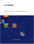
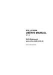
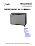
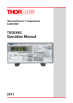
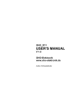
GOP_XC2C64
USER'S MANUAL
V 0.9
OHO-Elektronik
www.oho-elektronik.de
Author: M.Randelzhofer
OHO-Elektronik · Rudolf-Diesel-Str. 8 · D-85221 Dachau · Germany · www.oho-elektronik.de
OHO-Elektronik
Michael Randelzhofer
Rudolf-Diesel-Str. 8
85221 Dachau
Germany
WEB: www.oho-elektronik.de
EMAIL: [email protected]
Phone: +49 8131 339230
FAX: +49 8131 339294
©2005 OHO-Elektronik - Michael Randelzhofer
All rights reserved
Disclaimer:
Under no circumstances OHO-Elektronik - Michael Randelzhofer is liable for consequential
costs, losses, damages, lost profits.
Any schematics, pcb or program parts are under the copyright of OHO-Elektronik - Michael
Randelzhofer, and can only be reproduced by permission of this company.
The contents of this USER'S MANUAL are subject to change without notice.
However the main changes are listed in the revision table at the end of this document.
Products of OHO-Elektronik - Michael Randelzhofer are not designed for use in life support
systems, where malfunction of these products could result in personal injury.
The products of OHO-Elektronik - Michael Randelzhofer are intended for use in a laboratory test
environment only. They can generate radio frequency energy (depending on the downloaded
design and application), which can disturb local radio or TV equipment, and so they have not
been tested to be CE compliant.
If you encounter any technical problems or mistakes in this document, please contact
[email protected], serious hints are very appreciated.
Trademarks:
All brand names or product names mentioned are trademarks or registered trademarks of their
respective holders.
PAL and GAL are registered trademarks of Lattice Semiconductor Corp.
GOP_XC2C64 USER'S MANUAL V0.9
Page 2 of 24
OHO-Elektronik · Rudolf-Diesel-Str. 8 · D-85221 Dachau · Germany · www.oho-elektronik.de
1. Table of contents:
1.
2.
Table of contents: ..................................................................................................................................3
Introduction............................................................................................................................................5
2.1.
GOP_XC2C64 Features: ...............................................................................................................5
2.2.
GOP_XC2C64 Applications:.........................................................................................................5
2.3.
Xilinx XC2C64 CPLD Features: ...................................................................................................6
2.4.
Xilinx XC2C64 CPLD Disadvantages: .........................................................................................6
2.5.
GOP_XC2C64 Board Picures, Top And Bottom View.................................................................7
2.6.
GOP_XC2C64 Board In A Lab Environment. ..............................................................................8
3. GOP_XC2C64 Board Overview............................................................................................................9
3.1.
I/O Distribution..............................................................................................................................9
3.2.
JTAG Port....................................................................................................................................10
Power Suppy............................................................................................................................................11
3.3.
PAL / GAL Emulation Of 24 Pin And 20 Pin Devices ...............................................................11
4. CPLD Design Support .........................................................................................................................12
5. GOP_X2C64 I/O Voltage Levels ........................................................................................................13
6. Detailed XC2C64-7VQ44 CPLD Pinout Table...................................................................................14
7. CON2 DIL Connector Pinout Table ....................................................................................................16
8. CON4 Test Connector Pinout Table....................................................................................................17
9. CON3 Configuration Jumper options..................................................................................................17
10.
DIL Connector Layout.....................................................................................................................18
11.
Schematics .......................................................................................................................................19
12.
Module Layout Top View ...............................................................................................................20
13.
Module Layout Bottom View..........................................................................................................21
14.
Technical Specifications..................................................................................................................22
15.
Literature..........................................................................................................................................23
16.
USER'S MANUAL Revisions.........................................................................................................24
GOP_XC2C64 USER'S MANUAL V0.9
Page 3 of 24
OHO-Elektronik · Rudolf-Diesel-Str. 8 · D-85221 Dachau · Germany · www.oho-elektronik.de
GOP_XC2C64 USER'S MANUAL V0.9
Page 4 of 24
OHO-Elektronik · Rudolf-Diesel-Str. 8 · D-85221 Dachau · Germany · www.oho-elektronik.de
2. Introduction
The GOP_XC2C64 is a mini module composed of a CPLD device with a PAL / GAL compatible
24 pin DIL footprint. Many additional features make it useful and flexible:
2.1.
GOP_XC2C64 Features:
XC2C64-7VQ44C CPLD, a member of the XILINX CoolRunner-II family,
with a 24 or 20 pin PAL / GAL compatible DIL footprint
Xilinx Parallel Cable IV or Platform USB compatible download connector 14pin / 2mm,
an OHO-Elektronik low cost programmer is also availlable
Operating voltage from 2,7V to 3.6V
Serial resistors in the I/O and test connector pins helps to decrease ringing
Onboard Clock oscillator with 49.152 MHz for audio or RS232 applications
Reverse plug in protection
A red / green dual led
A 7-pin test connector for probing internal signals, or interconnecting several GOP's
Solder jumpers for additional ground connections.
Easy to reuse
Professional design, manufactured on a 4 layer PCB, Made in Germany
2.2.
GOP_XC2C64 Applications:
Rapid Prototyping
Fast evaluation of Xilinx CPLD's
Battery operated equipment
Hardware platform for VHDL / VERILOG / digital design introductory courses
GOP_XC2C64 USER'S MANUAL V0.9
Page 5 of 24
OHO-Elektronik · Rudolf-Diesel-Str. 8 · D-85221 Dachau · Germany · www.oho-elektronik.de
2.3.
Xilinx XC2C64 CPLD Features:
Document [1] and [2] lists lots of goodies, here are the best facts:
Fast and modern low power CPLD
4 logic arrays "16V40", each offers 40 array inputs with 16 macrocells and a 56 product
term PLA
Macrocells offer D ,T and Latch type memory elements with dedicated CE input,
Flipflops can toggle on rising, falling and both edges
3 global clocks and product term clock, 4 global tristate nets and a global set / reset net
Inputs have Schmitt Trigger option
Input registers with little setup time of 3,3ns typ. on a XC2C64-7 device
Lots of I/O standards
Free powerful VHDL / VERILOG / schematics / simulation design software availlable
(Webpack)
1000 reprogramming cycles, 20 years data retention
Widely used CPLD, lots of information availlable by XILINX Inc. and on the web
2.4.
Xilinx XC2C64 CPLD Disadvantages:
The following items are not relevant in most cases.
However they should be used as a checklist, wheather an application is affected.
Needs 1,8V core voltage, 3,6V maximum I/O voltage
Despite the PLA architecture, less product terms per macrocell than XC9500XL family
Inputs are not 5V tolerant
In rare cases, reprogramming is only possible, if no running clocks are applied to any
CPLD pin
GOP_XC2C64 USER'S MANUAL V0.9
Page 6 of 24
OHO-Elektronik · Rudolf-Diesel-Str. 8 · D-85221 Dachau · Germany · www.oho-elektronik.de
2.5.
GOP_XC2C64 Board Picures, Top And Bottom View.
GOP_XC2C64 USER'S MANUAL V0.9
Page 7 of 24
OHO-Elektronik · Rudolf-Diesel-Str. 8 · D-85221 Dachau · Germany · www.oho-elektronik.de
2.6.
GOP_XC2C64 Board In A Lab Environment.
GOP_XC2C64 USER'S MANUAL V0.9
Page 8 of 24
OHO-Elektronik · Rudolf-Diesel-Str. 8 · D-85221 Dachau · Germany · www.oho-elektronik.de
3. GOP_XC2C64 Board Overview
2mm - 14pin
JTAG - PORT
CON1
1
USER
DUO-LED
RED /
GREEN
XILINX
CPLD
XC2C64
XOSC
49.152
MHz
1
2
4
1
3
2mm - 4pin
Jumper Block
CON3
1-2: 20-Pin Ground
3-4: XOSC-Supply
0,1" /
2.54mm
24 - Pin
DIL
SOCKET
PLUG
CON2
Access
To 22
CPLD
Pins
Voltage Regulator
1,8V / 150mA
With Reverse
Protection
JP1
JP2
JP3
Solder Jumper
For Additional Ground
Connections
0.3" GAP
2.54mm / 7pin
Test Connector
CON4
3.1.
I/O Distribution
22 Xilinx XC2C64-7VQ44C CPLD I/O's are wired to a 24 pin DIL socket plug (CON2) on the
bottom of the module through 22Ω serial resistors. These resistors primarily reduces ringing.
Pin 1 and 2 of the DIL plug accesses global clock nets GCK0 and GCK1 inside the CPLD.
Pins 19, 20 accesses the global tristate net GTS2 and GTS3.
Pin 18 accesses the global set / reset net.
5 remaining I/O's are availlable to the front side test connector CON4, also through 22Ω series
resistors.
GOP_XC2C64 USER'S MANUAL V0.9
Page 9 of 24
OHO-Elektronik · Rudolf-Diesel-Str. 8 · D-85221 Dachau · Germany · www.oho-elektronik.de
Pin 2 of the connector accesses the global tristate net GTS1.
This pin also has a pullup resistor to VCC (R39). A 2.54mm jumper can be used to short pin 2 to
GND at pin 1 of the testconnector as a simple status input.
Pin 7 of the testconnector has an unmounted pullup resistor (R44) to the 3,3V supply voltage.
A crystal oscillator with an output frequency of 49,152MHz is connected to another I/O of the
CPLD. This oscillator can be disabled completely by removing its power supply at jumper block
CON3 position 3-4.
Please note, that this clock must be routed inside the CPLD to a global clock net, to insure
proper synchronous circuit operation.
Furthermore 2 I/O's are connected to a dual led, having a red and a green chip in it's case.
These leds can be lighted by driving a logical '1' to these I/O's.
The output for the red led has also access to the global tristate net GTS0
Finally 2 I/O's are connected to an RC network for demontration purpose.
A simple RC oscillator can be evaluated.
If the input pin 18 of the CPLD has an Scmitt Trigger attribute in the UCF-File, the RC oscillator
operates properly.
3.2.
JTAG Port
The CPLD JTAG signals are routed directly to the Xilinx standard 2mm 14pin JTAG port
connector CON1, supported from the Parallel cable IV, and Platform USB cable, see [5], [6].
Pin 1 of the port is connected to GND, which allows high speed programming with the above
cables.
Pins 12,13 and 14 of the JTAG port are not used on this module.
Please notice the pin orientation of JTAG port CON1:
GOP_XC2C64 USER'S MANUAL V0.9
Page 10 of 24
OHO-Elektronik · Rudolf-Diesel-Str. 8 · D-85221 Dachau · Germany · www.oho-elektronik.de
Power Suppy
The module can be powered at DIL pin 24 from 2,7 to 3,6 Volts.
Module GND pin is pin 12 in 24 pin mode, and pin 10 in 20 pin mode.
An onboard voltage regulator produces the CPLD core and I/O voltage of 3,3V.
The regulator [4] can source up to 150mA.
The module has a protection against reverse insertion, or reverse power connection.
In that case, the protection shorts the power supply by a polyfuse device.
The polyfuse recovers after deactivation of the power supply.
Burn through cycles of the polyfuse are limited.
For more information, please consult the data sheet.
Even so care should be taken when plugging the module.
Consider that a short pulse of several amps can damage the environment in which the module
is inserted.
ATTENTION !
Please note that an input voltage greater than 4V will destroy the module !!!
3.3.
PAL / GAL Emulation Of 24 Pin And 20 Pin Devices
As a general hint, the DIL plug should be protected mechanically with the supplied DIL sockets
as an adaptor.
In 24 pin mode of the module, a 24 pin socket should be used.
In 20 pin mode of the module, a 20 pin socket should be used.
Please insure, that pin 1 of the module is always pin 1 of a socket.
In the 20 pin mode, an additional GND connection must be done via a 2mm jumper on jumper
block CON3 at position 1-2, see Layout Top View. This adds GND to pin 10.
In rare cases additional GND connections are desired.
Pins 3, 14 and 23 can be shorted to GND with solder jumpers JP1, JP3, JP2 respectively, on
the bottom side of the module. These shorts should be soldered via a stereo microscope, to
insure, that there are no other invalid connections.
GOP_XC2C64 USER'S MANUAL V0.9
Page 11 of 24
OHO-Elektronik · Rudolf-Diesel-Str. 8 · D-85221 Dachau · Germany · www.oho-elektronik.de
4. CPLD Design Support
As for CoolRunner-II CPLD design [3], [9] and [11] are very recommended readings.
VHDL and UCF design templates for 20 and 24 pin configurations are availlable.
GOP_XC2C64 USER'S MANUAL V0.9
Page 12 of 24
OHO-Elektronik · Rudolf-Diesel-Str. 8 · D-85221 Dachau · Germany · www.oho-elektronik.de
5. GOP_X2C64 I/O Voltage Levels
The Collrunner-II CPLD series offer a broad variety of I/O voltage standards.
However on the GOP_X2C64, only the LVCMOS33 standard is supported.
[12] informs about Coolrunner-II I/O characteristics.
GOP_XC2C64 USER'S MANUAL V0.9
Page 13 of 24
OHO-Elektronik · Rudolf-Diesel-Str. 8 · D-85221 Dachau · Germany · www.oho-elektronik.de
6. Detailed XC2C64-7VQ44 CPLD Pinout Table
CPLD pin
function
*
FB2MC10
I/O/GCK2
(Schema
net name)
routed to
--
2
FB2MC12
3
FB2MC13
4
5
GND
FB4MC1
6
FB4MC2
7
VCCIO
8
FB4MC7
9
TDI
10
TMS
11
TCK
12
FB4MC11
13
FB4MC13
14
FB4MC14
15
16
VCCINT
FB4MC15
17
18
GND
FB3MC15
(PLD2)
CON2 pin6
(PLD3)
CON2 pin7
Power GND
(PLD5)
CON2 pin9
(PLD6)
CON2 pin8
(VCC_CR)
VCC
(LED_G)
LED1
(TDI)
CON1 pin10
(TMS)
CON1 pin4
(TCK)
CON1 pin6
(PLD12)
CON2 pin10
(PLD13)
CON2 pin11
(PLD14)
CON4 pin3
Power VCC
(RC_IN)
RC network
Power GND
(RC_OUT)
RC network
19
FB3MC14
20
FB3MC12
21
FB3MC11
22
FB3MC10
23
FB3MC6
24
TDO
Pin
1
(PLD19)
CON4 pin4
(PLD20)
CON4 pin5
(PLD21)
CON4 pin6
(PLD22)
CON2 pin14
(OSC)
XOSC1
(TDO)
CON1 pin8
UCF port
24pin**
1. Comment:
(20 pin)
gck2
Use as an internal clock node to the global clock net GCK2
If XOSC1 is used, but not routed to GCK0 or GCK1, use
this global net instead.
pin6
Connection to the 20/24pin DIL plug to pin6 via serial
(pin6) resistor
pin7
Connection to the 20/24pin DIL plug to pin7 via serial
(pin7) resistor
-Connection to the GND Layer of the PCB
pin9
Connection to the 20/24pin DIL plug to pin9 via serial
(pin9) resistor
pin8
Connection to the 20/24pin DIL plug to pin8 via serial
(pin8) resistor
-Power supply 3,3V input voltage from DIL pin 24
ledgn
--
Green led of the duo led
0 -> led off, 1 -> led on
JTAG interface, additional 47k pullup to VCC
--
JTAG interface, additional 47k pullup to VCC
--
JTAG interface, additional 47k pullup to VCC
pin10
(--)
pin11
(--)
tp3
-rcin
Connection to the 24pin DIL plug to pin10 via serial resistor
Short to GND by CON3 for 20pin DIL plug
Connection to the 24pin DIL plug to pin11 via serial resistor
Not used for the 20pin DIL plug
Test connector pin3
tp4
Power supply 1,8V from regulator TPS76318
Input to an RC network, can be used as an RC oscillator
output.
Connection to the GND Layer of the PCB
Output from an RC network, this is for demonstration, that
rc oscillators work reliably on CoolRunner-II devices with
Schmitt Trigger inputs
Test connector pin4
tp5
Test connector pin5
tp6
Test connector pin6
-rcout
pin14
(--)
osc
--
GOP_XC2C64 USER'S MANUAL V0.9
Connection to the 24pin DIL plug to pin14 via serial resistor
Not used for the 20pin DIL plug
Crystal oscillator input
This signal should be routed internally to a global clock net
JTAG interface
Page 14 of 24
OHO-Elektronik · Rudolf-Diesel-Str. 8 · D-85221 Dachau · Germany · www.oho-elektronik.de
25
26
27
GND
VCCIO
FB3MC3
FB1MC13
I/O/GSR
Power GND
Power VCC
(PLD27)
CON2 pin15
(PLD28)
CON2 pin16
(PLD29)
CON2 pin17
(PLD30)
CON2 pin18
--pin15
(pin11)
pin16
(pin12)
pin17
(pin13)
pin18
(pin14)
28
FB3MC2
29
FB3MC1
30
31
FB1MC12
I/O/GTS2
(PLD31)
CON2 pin19
pin19
(pin15)
32
FB1MC11
I/O/GTS3
(PLD32)
CON2 pin20
pin20
(pin16)
33
FB1MC10
I/O/GTS0
(LED_R)
LED1
ledrd
34
FB1MC9
I/O/GTS1
(PLD34)
CON4 pin2
tp2
35
36
VAUX
FB1MC3
37
FB1MC2
38
FB1MC1
39
FB2MC1
40
FB2MC2
41
FB2MC5
42
FB2MC6
43
FB2MC7
I/O/GCK0
JTAG VCC
(PLD36)
CON2 pin13
(PLD37)
CON2 pin21
(PLD38)
CON2 pin22
(PLD39)
CON2 pin23
(PLD40)
CON2 pin3
(PLD41)
CON2 pin4
(PLD42)
CON2 pin5
(PLD43)
CON2 pin10
-pin13
(--)
pin21
(pin17)
pin22
(pin18)
pin23
(pin19)
pin3
(pin3)
pin4
(pin4)
pin5
(pin5)
pin1
(pin1)
44
FB2MC8
I/O/GCK1
(PLD44)
CON2 pin10
pin2
(pin2)
Connection to the GND Layer of the PCB
Power supply 3,3V input voltage from DIL pin 24
Connection to the 24pin DIL plug to pin15 via serial resistor
Connection to the 20pin DIL plug to pin11 via serial resistor
Connection to the 24pin DIL plug to pin16 via serial resistor
Connection to the 20pin DIL plug to pin12 via serial resistor
Connection to the 24pin DIL plug to pin17 via serial resistor
Connection to the 20pin DIL plug to pin13 via serial resistor
Connection to the 24pin DIL plug to pin18 via serial resistor
Connection to the 20pin DIL plug to pin14 via serial resistor
Global set / reset net
Connection to the 24pin DIL plug to pin19 via serial resistor
Connection to the 20pin DIL plug to pin15 via serial resistor
Global tristate net GTS2
Connection to the 24pin DIL plug to pin20 via serial resistor
Connection to the 20pin DIL plug to pin16 via serial resistor
Global tristate net GTS3
Red led of the duo led
0 -> led off, 1 -> led on
Global tristate net GTS0
Test connector pin2, R38 is soldered to the 3,3V supply
voltage, as a pullup on tp2.
Tp2 can be used as a simple input by shorting to tp1
This is also an input to the global tri state net GTS1
Power supply 3,3V input voltage from DIL pin 24
Connection to the 24pin DIL plug to pin13 via serial resistor
Not used for the 20pin DIL plug
Connection to the 24pin DIL plug to pin21 via serial resistor
Connection to the 20pin DIL plug to pin17 via serial resistor
Connection to the 24pin DIL plug to pin22 via serial resistor
Connection to the 20pin DIL plug to pin18 via serial resistor
Connection to the 24pin DIL plug to pin23 via serial resistor
Connection to the 20pin DIL plug to pin19 via serial resistor
Connection to the 20/24pin DIL plug to pin3 via serial
resistor
Connection to the 20/24pin DIL plug to pin4 via serial
resistor
Connection to the 20/24pin DIL plug to pin5 via serial
resistor
Connection to the 20/24pin DIL plug to pin1 via serial
resistor
This is also an input to the global clock net 1 GCK0
Connection to the 20/24pin DIL plug to pin2 via serial
resistor
This is also an input to the global clock net 2 GCK1
* FB1MC11 denotes function block1, macrocell 11
** There is an UCF file definition for 24pin, and another one for 20pin device usage
GOP_XC2C64 USER'S MANUAL V0.9
Page 15 of 24
OHO-Elektronik · Rudolf-Diesel-Str. 8 · D-85221 Dachau · Germany · www.oho-elektronik.de
7. CON2 DIL Connector Pinout Table
Pin
CPLD pin
function
*
1
FB2MC7
I/O/GCK0
2
FB2MC8
I/O/GCK1
3
FB2MC2
4
FB2MC5
5
FB2MC6
6
FB2MC12
7
FB2MC13
8
FB4MC2
9
FB4MC1
10
FB4MC11
11
FB4MC13
12
13
GND
FB1MC3
14
FB3MC10
15
FB3MC3
16
FB3MC2
17
FB3MC1
18
FB1MC13
I/O/GSR
19
FB1MC12
I/O/GTS2
20
FB1MC11
I/O/GTS3
21
FB1MC2
UCF
(Schema
net name)
port
Comment
routed to
name **
(PLD43)
pin1
Connection to the 20/24pin DIL plug to pin1 via serial
CON2 pin10
(pin1) resistor
This is also an input to the global clock net 1 GCK0
(PLD44)
pin2
Connection to the 20/24pin DIL plug to pin2 via serial
CON2 pin10
(pin2) resistor
This is also an input to the global clock net 2 GCK1
(PLD40)
pin3
Connection to the 20/24pin DIL plug to pin3 via serial
CON2 pin3
(pin3) resistor
(PLD41)
pin4
Connection to the 20/24pin DIL plug to pin4 via serial
CON2 pin4
(pin4) resistor
(PLD42)
pin5
Connection to the 20/24pin DIL plug to pin5 via serial
CON2 pin5
(pin5) resistor
(PLD2)
pin6
Connection to the 20/24pin DIL plug to pin6 via serial
CON2 pin6
(pin6) resistor
(PLD3)
pin7
Connection to the 20/24pin DIL plug to pin7 via serial
CON2 pin7
(pin7) resistor
(PLD6)
pin8
Connection to the 20/24pin DIL plug to pin8 via serial
CON2 pin8
(pin8) resistor
(PLD5)
pin9
Connection to the 20/24pin DIL plug to pin9 via serial
CON2 pin9
(pin9) resistor
(PLD12)
pin10
Connection to the 24pin DIL plug to pin10 via serial resistor
CON2 pin10
(--)
Short to GND by CON3 for 20pin DIL plug
(PLD13)
pin11
Connection to the 24pin DIL plug to pin11 via serial resistor
CON2 pin11
(--)
Not used for the 20pin DIL plug
GND
-Power ground plane connection
(PLD36)
pin13
Connection to the 24pin DIL plug to pin13 via serial resistor
CON2 pin13
(--)
Not used for the 20pin DIL plug
(PLD22)
pin14
Connection to the 24pin DIL plug to pin14 via serial resistor
CON2 pin14
(--)
Not used for the 20pin DIL plug
(PLD27)
pin15
Connection to the 24pin DIL plug to pin15 via serial resistor
CON2 pin15 (pin11) Connection to the 20pin DIL plug to pin11 via serial resistor
(PLD28)
pin16
Connection to the 24pin DIL plug to pin16 via serial resistor
CON2 pin16 (pin12) Connection to the 20pin DIL plug to pin12 via serial resistor
(PLD29)
pin17
Connection to the 24pin DIL plug to pin17 via serial resistor
CON2 pin17 (pin13) Connection to the 20pin DIL plug to pin13 via serial resistor
(PLD30)
pin18
Connection to the 24pin DIL plug to pin18 via serial resistor
CON2 pin18 (pin14) Connection to the 20pin DIL plug to pin14 via serial resistor
Global set / reset net
(PLD31)
pin19
Connection to the 24pin DIL plug to pin19 via serial resistor
CON2 pin19 (pin15) Connection to the 20pin DIL plug to pin15 via serial resistor
Global tristate net GTS2
(PLD32)
pin20
Connection to the 24pin DIL plug to pin20 via serial resistor
CON2 pin20 (pin16) Connection to the 20pin DIL plug to pin16 via serial resistor
Global tristate net GTS3
(PLD37)
pin21
Connection to the 24pin DIL plug to pin21 via serial resistor
CON2 pin21 (pin17) Connection to the 20pin DIL plug to pin17 via serial resistor
GOP_XC2C64 USER'S MANUAL V0.9
Page 16 of 24
OHO-Elektronik · Rudolf-Diesel-Str. 8 · D-85221 Dachau · Germany · www.oho-elektronik.de
22
FB1MC1
23
FB2MC1
24
--
(PLD38)
CON2 pin22
(PLD39)
CON2 pin23
PIN_24
pin22
(pin18)
pin23
(pin19)
--
Connection to the 24pin DIL plug to pin22 via serial resistor
Connection to the 20pin DIL plug to pin18 via serial resistor
Connection to the 24pin DIL plug to pin23 via serial resistor
Connection to the 20pin DIL plug to pin19 via serial resistor
3,3V input voltage to the module
8. CON4 Test Connector Pinout Table
Pin
1
2
3
4
5
6
7
UCF
CPLD pin (Schema
port
Comment
function net name)
routed to
name **
*
GND
GND
-Power ground plane connection
FB1MC9
(PLD34)
tp2
Test connector pin2, R38 is soldered to the 3,3V
I/O/GTS1 CON4 pin2
supply voltage, as a pullup on tp2.
Tp2 can be used as a simple input by shorting to tp1
This is also an input to the global tri state net GTS1
FB4MC14
(PLD14)
tp3
Test connector pin3
CON4 pin3
FB3MC14
(PLD19)
tp4
Test connector pin4
CON4 pin4
FB3MC12
(PLD20)
tp5
Test connector pin5
CON4 pin5
FB3MC11
(PLD21)
tp6
Test connector pin6
CON4 pin6
-(VCC_IN)
-3,3V input voltage protected by a polyfuse
PIN24
9. CON3 Configuration Jumper options
1-2
3-4
Enable 20pin PAL / GAL Emulation, put GND to pin 10 of CON2
Enable XOSC1 crystal oscillator 49,152 MHz
GOP_XC2C64 USER'S MANUAL V0.9
Page 17 of 24
OHO-Elektronik · Rudolf-Diesel-Str. 8 · D-85221 Dachau · Germany · www.oho-elektronik.de
10. DIL Connector Layout
GOP_XC2C64 module top view for 24 pin and 20 pin emulation mode:
GOP_XC2C64 USER'S MANUAL V0.9
Page 18 of 24
OHO-Elektronik · Rudolf-Diesel-Str. 8 · D-85221 Dachau · Germany · www.oho-elektronik.de
11.
Schematics
GOP_XC2C64 USER'S MANUAL V0.9
Page 19 of 24
OHO-Elektronik · Rudolf-Diesel-Str. 8 · D-85221 Dachau · Germany · www.oho-elektronik.de
12. Module Layout Top View
GOP_XC2C64 USER'S MANUAL V0.9
Page 20 of 24
OHO-Elektronik · Rudolf-Diesel-Str. 8 · D-85221 Dachau · Germany · www.oho-elektronik.de
13. Module Layout Bottom View
GOP_XC2C64 USER'S MANUAL V0.9
Page 21 of 24
OHO-Elektronik · Rudolf-Diesel-Str. 8 · D-85221 Dachau · Germany · www.oho-elektronik.de
14. Technical Specifications
CPLD:
Supply Voltage on PIN24:
Size:
Height PCB to Top:
Height PCB to Bottom:
Weight:
Xilinx XC2C64-7VQ44C
2,7 - 3,6V
40,5 x 20mm, 1,594" x 0,787"
max. 8mm, 0,315"
max. 12mm, 0,472"
7g
GOP_XC2C64 USER'S MANUAL V0.9
Page 22 of 24
OHO-Elektronik · Rudolf-Diesel-Str. 8 · D-85221 Dachau · Germany · www.oho-elektronik.de
15. Literature
[1] DS090 Coolrunner-II CPLD Family Data Sheet
http://direct.xilinx.com/bvdocs/publications/ds090.pdf
[2] DS092 XC2C64 64 Macrocell Coolrunner-II CPLD
http://direct.xilinx.com/bvdocs/publications/ds092.pdf
[3] XAPP444 CPLD Fitting, Tips and Tricks
http://direct.xilinx.com/bvdocs/appnotes/xapp444.pdf
[4] TPS76318 Low Power 150mA Low Dropout Linear Regulators
http://focus.ti.com/lit/ds/symlink/tps76318.pdf
[5] DS097 Xilinx Parallel Cable IV
http://direct.xilinx.com/bvdocs/publications/ds097.pdf
[6] DS300 Platform Cable USB
http://direct.xilinx.com/bvdocs/publications/ds300.pdf
[9] XAPP784 Bulletproof CPLD Design Practices
http://direct.xilinx.com/bvdocs/appnotes/xapp784.pdf
[10] XAPP805 Driving Leds with Xilinx CPLD's
http://direct.xilinx.com/bvdocs/appnotes/xapp805.pdf
[11] XAPP378 Using CoolRunner-II Advanced Features
http://direct.xilinx.com/bvdocs/publications/xapp378.pdf
[12] XAPP382 CoolRunner-II I/O Characteristics
http://direct.xilinx.com/bvdocs/appnotes/xapp382.pdf
GOP_XC2C64 USER'S MANUAL V0.9
Page 23 of 24
OHO-Elektronik · Rudolf-Diesel-Str. 8 · D-85221 Dachau · Germany · www.oho-elektronik.de
16. USER'S MANUAL Revisions
Version
Date
V0.9 23/10/2005
GOP_XC2C64 USER'S MANUAL V0.9
Comments
Prerelease
Page 24 of 24