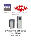
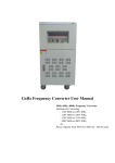
1
LOW FREQUENCY ON LINE UPS
TThhrreeee pphhaassee iinn aanndd tthhrreeee pphhaassee oouutt
Users Manual
TToouucchh ssccrreeeenn UUPPSS ((1100--112200))KKVVAA
1.Brief introduction
8900 (3 phase in and 3phase out) series UPS is large power and true on–line UPS with range from 10KVA to 120KVA, which adopts
advanced digital design, high speed 16–bit chip, ASIC, DDC and large power IGBT&SCR, and shows large capacity, high stability and
super performance compared with usual models on the market. All the products have integrated the latest hardware and powerful software in
itself, which could provide optimum pure power to integrated server center. This system supports several units connected in parallel through
unique control technology.
The liquid crystal display of touch-sensitive screen is that UPS which our company develops newly shows the module, adopt nowadays
most popular, most ocular figure operate interfaces. Compared with the situation that general LCD shows the module, this touch-sensitive
screen shows the operating sequence without complicatedness of the module, users press the simulation button on the display and can obtain
corresponding information directly, operate and is easily understood; and it brings real-time clock and memory by oneself, can write down
256 information and other establishment message.
2.Operation demand
Please read carefully the user manual before using machine.
This manual must be understood and conserved by professional.。
This manual does not introduce the detail specification.
This manual just suit to 8900 (3 phase in and 3phase out) series UPS.
3.Notices
3.1 Make sure relevant power input/output/battery/cable.
3.2.It must be steady grounding system.
3.3. There are a lot of high-voltage energy storage device in Machine, please don't open case and check, otherwise cause danger to lift,
accept the consequences by oneself. The operator must understand the electrician basic knowledge and pore over the operation
instructions.
3.4. Without permission, can't dismantle various kinds of connection cables without authorization.
3.5. Because this product is greater in volume, weight is relatively heavy, can't move at will, must not split and shake strongly Move,
and keep ventilating it well.
3.6. In case of electrification, can't go to discharge the dust; Handy wet towel go to wipe and get rid of the dirt.
3.7. The battery must be changed by the professional and technical personnel, the battery changed out must deliver special circulation
and give a new lease of life to the organization to deal with . The battery is " poisonous waste material "
3.8. UPS is not used when being installed a long time, the battery disposed will discharge automatically, at the same time the automatic
consumption that chemical energy of the battery, at 25 degrees Centigrade according to the environmental climate around,, the battery
must be charged in every three months, if the temperature is greater than 30 degrees Centigrade, the battery should be charged once every
two months . Only need to start UPS while charging, and run at least for 24 hours under the normal work pattern.
4、working principle
4.1.8900 3/3 series UPS adopts advanced digital design, ,improved MTBF and steadily,one lone main control panel control all
system. Which adopts microprocessor control and ensure that machine can
1
work steadily and reliably.
Besides, UPS others parts: invert transformer, input inductance, IGBT, silicon controlled and switch.
4.2.Standard UPS principle :
4.3.Mains inverter principle:
After AC input turn to DC filter through rectifier, then inverter invert through SPWM and output AC.
4.3.1.Normal inverter model:
Battery have been recharge full, after AC rectifier, then inverter output.
2
4.3.2. Inverter normally, and battery recharge working model:
battery voltage is low, after AC inverter, on one hand it will charge, on the other inverter output.
4.3.3. AC input failure, battery-working model:
AC input is failure, battery inverter and supply power.
4.3.4.Bypass output working model:
There is AC input, but inverter has been closed, meantime, output is supplied bypass.
4.4. Function module
4.4.1.Rectifier
3
Protection short circuit rectifier switch
Lightning arrestor
6/12 Plus rectifier
Input inductance
Battery temperature compensate
Battery floating charging
Battery timing balanced charging.
The input of rectifier can be limited in rated numerical value, at the same time , battery recharge in constant current,
constant voltage, expert engineer can change rectifier working through setting parameter.
4.4.2.Inverter
Inverter output isolation transformer.
3 Phase PWM inverter bridge.
Current sampling
Voltage sampling
Feedback control
Self–testing
Hardware sense
Protection circuit
4
5.Front panel introduction
1
+
-
!
F1
F2
2
5
4
整
流
旁
RECTIFIER
3
路
输
BYPASS
出
电
OUTPUT
维修旁路
池
BATTERY
ON
ON
ON
ON
ON
OFF
OFF
OFF
OF F
OFF
E
R
S
T
N
R
S
T
N
+
6
MANUAL BYPASS
-
7
E
RS232
RS232
RS232
9
8
(1) LCD display------it indicates various kinds of data
(2) LED statue display-----it indicates working statue
(3 Input rectifier switch ------Control rectifier input
(4) Bypass switch ------Control bypass input.
(5) Output switch ------Control output
(6) Battery switch ------Control battery input
(7) Maintenance bypass switch ------Control AC bypass (just use it when maintenance)
(8) Line bank------Connect input, output, battery and grounding.
(9)RS232 communication port
6、INSTALLATION
6.1.Installation environment:
Temperature:0℃~+40℃
Relative humidity:30%~90%
Altitude:≤1000M
Installation environment dimension(L×W×H):
2000×2000×2000
Board pressure:3000KG/M2
The indoor environment demanded is as following:
No dust
Appropriate indoor temperature: please operate UPS in 0~40℃,
But it is 0℃when start, the idea operation temperature is 25℃.
There should be a good heat dissipation system, the following is a feasible method:
A: Natural ventilating system: Only suitable for low heat and vast space.
B: man - made ventilating systems: Need to install the air conditioner when exceeds the peripheral temperature (TE) in chassis
temperature (TA). As the TE and TA is close, the capacity of the heat distribution system will increase.
6.2. Check before installation:
Unpack the equipment and inspect again to determine if any external or internal damage has occurred.
Opening the main entrance, meantime, please check if all switches are disconnection.
5
6.3.Installation site:
Please place the UPS in the place where keeps good ventilation, rear panel of UPS and two side faces should keep more than
80cm away from the wall.
Do not lay goods on the UPS.
It must have enough room to Overhaul in the front of equipment and above.
Battery box of equipment must keep enough position on right-hand side for battery overhaul.
Power line must be connected from bottom of machine.
6.4.Terminal connection diagram:
E
R
S
T
N
N
R
S
Output
Input
T
+
E
-
Battery
Grounding
Before UPS is not being installed, please disconnect all switches.
Left: R、S、T、N connect three phase input phase line and median line ;
Right :N 、R 、S、T connect three phase output phase line and median line;
E connect earth line;+、- connect battery positive pole and negative pole.
6.5.UPS three output system 5-200KVA cable specification:
(unit: mm2)
Input
capacity
R
S
Output
T
N
E
R
S
Battery
T
N
+
-
5KVA
4
4
4
4
4
4
4
4
4
6
6
10KVA
6
6
6
6
6
6
6
6
6
10
10
20KVA
10
10
10
10
10
10
10
10
10
20
20
30KVA
16
16
16
16
16
16
16
16
16
30
30
50KVA
25
25
25
25
25
25
25
25
25
50
50
80KVA
40
40
40
40
40
40
40
40
40
80
80
100KVA
50
50
50
50
50
50
50
50
50
100
100
120KVA
60
60
60
60
60
60
60
60
60
120
120
150KVA
75
75
75
75
75
75
75
75
75
150
150
200KVA
100
100
100
100
100
100
100
100
100
200
200
6.6.Battery connection
Opening battery pack.
Installation battery on the corresponding position and connecting the good battery connecting wire
6.7.connection inspection
connect all input/output/battery/wire,check under matters:
Whether all battery-connecting wires join correctly and keep in touch well,
6
Input, output, the earth connection has already been connected in the corresponding wiring on the equipment is arranged correctly,
The voltage of input end, frequency, phase should keep the same with voltage of bypass, frequency, and phase.
7、Specification
7.1 UPS series specification
7.1.1. Rectifier input parameter; Please refer to the following table 2
Table 2
10
15
20
30
40
50
60
80
100
120
KVA
KVA
KVA
KVA
KVA
KVA
KVA
KVA
KVA
KVA
Capacity (KVA)
10
15
20
30
40
50
60
80
100
120
Input single max. current
50
66
80
110
142
172
204
266
328
390
Model
On line,static bypass switch (zero transfer time ), Double switch technology, output
Working way and principle
power to totally isolate
Phase
3phase +N+G
Nominal voltage
380VAC±25%
Nominal frequency
50Hz±10%,60Hz±10%
Voltage harmonics distortion
<10%
Soft start
0~100% 5sec
7.1.2. Rectifier output parameter; Please refer to the following table 3
Table 3
Model
10
15
20
30
40
50
60
80
100
120
KVA
KVA
KVA
KVA
KVA
KVA
KVA
KVA
KVA
KVA
Max. output voltage
405VDC
Microcomputer setting
3A~30A(depend on battery capacity)
charge current
7.2 Battery
Please refer to the following table 4
Table 4
Model
Max.discharge current(A)
10
15
20
30
40
50
60
80
100
120
KVA
KVA
KVA
KVA
KVA
KVA
KVA
KVA
KVA
KVA
28
42
56
85
113
141
169
225
282
338
Battery quantity
30pcs
Nominal battery voltage
360VDC
Floating voltage
405VDC
Charge current
3A~30A(depend on battery capacity)
7
7.3 Inverter specification
Inverter
Please refer to the following table 5
Table 5
Model
10
15
20
30
40
50
60
80
100
120
KVA
KVA
KVA
KVA
KVA
KVA
KVA
KVA
KVA
KVA
8
12
16
24
32
40
48
64
80
96
Rated power (KW)
COSφ=0.8
Phase
3phase +N+G
Nominal voltage
380VAC±1%(steady load),380VAC±5%(load fluctuate)
Nominal frequency
50Hz±0.05%,60Hz±0.05%(battery supply power)
Frequency stability:
<±0.05%
Out sync
Frequency stability:
<±2%
Synchronization
Crest factor
3:1
Output wave
Sine wave
Total harmonic distortion
Linearity load <3%;non-linearity load<5%
Dynamic load voltage
transient
<±5%
(from 0 to 100% abrupt
change)
Moment restart time
<10ms
Balance load voltage
<±1%;<±5%(imbalance load voltage)
Overload capability
125% 1min,150% 1S
Inverter efficiency,load
100%
7.4 Bypass
91
91
92
92
93
93
93
95
95
95
Please refer to the following table 6
Table 6
Model
10
15
20
30
40
50
60
80
100
120
KVA
KVA
KVA
KVA
KVA
KVA
KVA
KVA
KVA
KVA
Phase
3phase +N+G
Nominal voltage
3800VAC±25%
Nominal frequency
50Hz±5%,60Hz±5%
Inverter /bypass(transfer
(overload)0ms
time)
8
7.5 systems specification:
Please refer to the following table 6
Table 6
Model
10
15
20
30
40
50
60
80
100
120
KVA
KVA
KVA
KVA
KVA
KVA
KVA
KVA
KVA
KVA
Efficiency load 100%
>80%
PC communication interface
RS232
Working temperature
0~40℃
Humidity
30%~90%
(non~condensing)
Working height(Max.)
<1000m(per100m, power decline 1%,Max.4000m)
Type of cooling
Forced draught
Noise dB(according to load
and temperature)far away
40~50
45~55
55~65
machine 1M
Case color
Gray (option)
Input cable
The bottom / back
Easy maintenance
The front / the above / left and right
Dimension
600×700×
710×720×
W×D×H(mm)
1350
1450
Weight(kg)
200
300
400
710×850×1500
460
550
620
Input device
Terminal
Output device
Terminal
700
1100×860×1680
860
900
950
*For reference only above data, EAST GROUP reserves the right to implement changes to the above content without prior announcement.
8.Alarming
8.1 Alarming 1:Bypass voltage failure or bypass fuse SCR failure.
It will alarm under these conditions:
1. Bypass input voltage is wrong.
2. Bypass input switch cut off.
3. Bypass SCR fuse cut off or burned because of output short circuit or fuse cut off.
8.2 Alarming 2:Main input power failure or rectifier input switch cut off.
It will alarm under these conditions:
1. Input voltage is not in the range(90~150)VAC.
2. Input frequency is not in the range(57~62.5)Hz.
3. Rectifier input switch cut off.
4. Because UPS is abnormal and cause one phase of three phase rectifier can not work normally, please find out the failure thought
consult contents.
8.3Alarming 3:Battery low voltage
It will alarm under these conditions:
1. Battery voltage is too low.
2. The time battery running is shorter than setting time.
9
8.4 Alarming 4:Battery discharge
When battery discharge, it will alarm at once, after 2 minutes, alarm will stop. Once battery discharge is up to battery final voltage,
alarm again.
8.5 Alarming 5:Output overload.
When load power is bigger than rated output voltage, namely,
more than 100 %,if load current is over big, UPS will alarm. When UPS
alarm, it needs to reduce load capacity. Or UPS will turn to bypass, we get the time depend on over load value’s inverse ratio.
8.6 Alarming 6:Temporality bypass working
It indicates bypass supply power; UPS will turn to normally run statue (inverter supply power). There are some conditions under this
temporality statue, for example, overload, after bypass supply power, UPS is waiting for power supplied by inverter.
8.7 Alarming 7:Bypass output overload
If overload time is too long, for example, overload 125%, inverter can supply power 1min. then turn to bypass. UPS will renew normal
running statue.
8.8 Alarming 8:High temperature or fan failure
When control system of UPS, inverter power module or rectifier power module is over temperature because of high temperature or fan
failure, UPS turn to bypass.
9.UPS start up process
It must be operated to obey these sequence, thought there is battery switch in UPS.
Start up UPS:
9.1.Open input rectifier switch(Up).
9.2.Open bypass switch(UP)
9.3.After battery low voltage indicator crust out, then open battery switch. When UPS is no any alarm statue indicator, bypass will turn
to inverter statue.
Notice:it will display alarming information about the wrong phase sequence if rectifier switch is not cut
off, at this time, please press F1 and silence, carry out UPS start up process.
10.UPS maintenance shut down process
10.1.open maintenance switch(up)
10.2.close battery switch(down)
10.3.close rectifier switch(up)
10.4.close bypass switch(down)
10.5.close UPS output switch(down)
11. Emergency shut down process
When it happens to fire, electric shock, electric arc or other dangerous. user can read this process and operate, but it maybe cause the
dangerous that no AC output.
——Make all switches cut off
12.Touch screen Introductions
The liquid crystal display of touch-sensitive screen is that UPS which our company develops newly shows the module, adopt nowadays
most popular, most ocular figure operate interfaces. Compared with the situation that general LCD shows the module, this touch-sensitive
screen shows the operating sequence without complicatedness of the module, users press the simulation button on the display and can obtain
corresponding information directly, operate and is easily understood; and it brings real-time clock and memory by oneself, can write down
256 information and other establishment message.
13.Operating interface introductions
13.1 watchful waiting picture
It will show the watchful waiting picture when UPS starts the machine. When the interval of the touch-sensitive screen is not touched for
four minutes , CPU will cut off the power in a poor light of touch-sensitive screen automatically , this way can lengthen in a poor light
10
service life , and come back watchful waiting picture (if UPS is under warning state to get back to at the same time, the touch-sensitive
screen will have priority to show the warning information frame , CPU can not cut off touch-sensitive screen in a poor light power before
canceling warning information).
13.2 The flow chart interface
When the touch screen is under watchful waiting picture, you can touch it anywhere and enter into the flow chart interface. You can know
the basic information and working statue about this UPS. Every part of meaning in the picture is as follows:
⑴Mains:Press it, you can look at the Mains input statue and data display.
⑵UPS basic information:Display UPS basic information, include manufacturer. UPS model and version number.
⑶Thin dotted line : It shows with detailed dotted line that the module has stopped to work.
⑷Heavy line:It shows with detailed dotted line that the module is working.
⑸Output:Press it, you can look at the UPS output statue and data display.
⑹Inverter:Press it, you can look at inerter working statue and data display.
⑺The systematic parameter establishes the module : It can set up time and langue.
⑻UPS serial No.:it display UPS products serial number.
⑼Battery:Press it, you can look at battery working statue and data display.
⑽system time: it can display time.
⑾slave marks:it show this UPS is working when it is parallel connection.
⑿systems manage module:it can control UPS and consult the system records.
⒀rectifier :Press it, you can look at the rectifier working statue and data display.
3
2
4
1
5
13
6
12
7
11
10
9
8
Picture 2.
13.3 Measure data display interface.
Press Mains key , output key , inverter key ,battery key and rectifier key, then enter into corresponding measure data display interface,
please consult the picture 3 and it show the output information and data display. Every part of meaning in the picture is as follows:
⑴Form subject
⑵Form contents:All kinds of statue and data display
⑶System time:System time display
⑷Back space:Press button this return to the catalogue at a higher level
⑸ESC: Press this button and withdraw from all catalogues and get back to watchful waiting picture.
11
UPS AC output check and measure
1
2
2
AC output voltage(V)
220
220
220
AC output frequency(Hz)
50.0
50.0
50.0
AC output current(A)
00.0
00.0
00.0
Load capacity (%)
000
000
000
Bypass switch working statue
ON
Inverter switch working statue
OFF
5
3
4
2004-10-01
00:00:00
Picture 3.
13.4 Display panel introductions
9
4
3
5
1
6
8
2
7
13.5 LED and press button introduction:
(1)Mains input indictor (2)Bypass indictor (3)Inverter indicator (4)Battery low voltage indicator(5)Overload indicator (6)
system abnormal indicator
(7)F1: combined key /silencing key (8)F2: shut up, Press F1 and F2 at the same time and shut down
UPS,Press F1 and enter into set up model .
13.6 Manage interface introductions
Press system manage module when the flow chart interface display, then enter into manage interface and press corresponding button.
Every part of meaning in the picture is as follows:
⑴ON/OFF:When UPS is closed,the key display‘ON’,Press this button and start UPS;when UPS is started,the key display ‘OFF’,
press this button and close the UPS(system will demand to import password in order to avoid mistake ).
⑵Battery measure button:When UPS is working, press this and enter into battery measure model.(system will demand to import
password in order to avoid mistake)
⑶about…:Press this button and consult the touch screen version number information.
⑷silencing:Make the buzzer silence.(system will demand to import password)
⑸UPS current working statue.
12
⑹ESC:Press this button and withdraw from all catalogues and get back to watchful waiting picture.
⑺Back space:Press button this return to the catalogue at a higher level
⑻Help:Press this button and consult help information.
⑼System information:Press this button and consult UPS’s information.
⑽system records:Press this button and consult all history records.
2
4
1
5
10
9
6
3
8
7
Picture 4.
13.6.1 Import password interface
Some operation will change the present working state of UPS, for instance: ON / OFF system, system at this moment will require
operator input password of operating, otherwise not carrying out. The initial operation password when the system is dispatched from the
factory is 1234.please consult the picture 5. Every part of meaning the following in the picture
⑴Password:It display password number, user input the password, then the number will interest of’ * ’.
⑵Number button:Input corresponding number.。
⑶Enter:After (2), press this button and enter into interface.
⑷ESC:Withdraw from the introduction password communication frame
When the password is right, system will carry out corresponding operation.
1
2
4
3
Picture 5
13.6.2 History records interface
Press system history records button when the manage interface display, and then enter into history records interface and press
13
corresponding button. Every part of meaning in the picture is as follows:
⑴The permutation order in the memory of the incident, the newest incident is arranged foremost, the serial number is minimum
⑵Incident code
⑶Incident time:Time records when it has happened.
⑷incident description :It describes the incident type.
⑸UP:Consult above 8 pieces incident records.
⑹Down: Consult above 8 pieces incident records.
⑺ESC:Press this button and withdraw from all catalogues and get back to watchful waiting picture.
⑻Back space: Press this button and consult all history records.
Incident record
1
No.
000
2
001
002
3
003
004
Code
044
002
001
031
000
Time
2004-10-01
00:00:03
2004-10-01
00:00:00
2004-10-01
00:00:00
2004-09-30
00:00:00
2000-00-00
00:00:00
Incident
4
Silencing alarming
Battery low voltage
Input unusual
6
Transmit the trouble
No
8
5
2004-10-01
00:00:00
7
Picture 6
13.6.3 Current UPS working statue
Press current working statue button when the manage interface display, and then enter into current UPS working statue interface and
press corresponding button. Every part of meaning in the picture is as follows:
⑴it shows current UPS working statue.
⑵ESC:Press this button and withdraw from all catalogues and get back to watchful waiting picture.
⑶Back space: Press this button and consult all history records.
UPS current working statue
UPS has been shut down, battery low voltage, input unusual,
1
bypass
Output
2
3
2004-10-01
00:00:00
14
13.7 Setup display interfaces
As picture 8 shows set up the picture of showing. Click with hand systematic parameter establish module button can be entered and set
up the picture of showing at flow chart picture of showing. Then press the corresponding button and can alter the systematic parameter
of UPS in this picture. Every part of meaning in the picture is as follows:
⑴Time setup button:It can change system time.(system will demand to import password in order to avoid mistake)
⑵langue setup button:You can choose one langue, ENGLISH /CHINESE.
⑶Help:Press this button and ask for some help.
⑷Back space: Press this button and consult all history records.
⑸ESC:Press this button and withdraw from all catalogues and get back to watchful waiting picture.
⑹Cancel button:Cancel all history records.(system will demand to import password in order to avoid mistake)
⑺Revise the password: Revise the systematic operation password. In order to prevent operating by mistake, the system will require the
old operation password of introduction. Require introduction twice while inputting the new password, if the new password input twice is
unanimous, the new password is set up and finished.
1
7
6
2
5
3
4
Picture 7.
13.7.1 Import password interface
Some operation will change the present working state of UPS, for instance: ON / OFF system, system at this moment will require
operator input password of operating, otherwise not carrying out. The initial operation password when the system is dispatched from the
factory is 1234. Please consult the 13.6.1 about the operation.
13.7.2Time setup interface
Press time setup button and input right password when the setup interface display, then enter into the time setup interface. This
interface is mainly for inputting the new systematic clock; the interface is as picture 9. Shows. Every part of meaning in the picture is as
follows:
⑴Year:Show in year inputting the new clock. Before there is no new figure, and use '? ' Express; When users import new number value
from the figure button, show the digital value that users input.
⑵Month:Show in month inputting the new clock. Before there is no new figure, and use '? ' express; When users import new number
value from the figure button, show the digital value that users input..
⑶Date:Show in date inputting the new clock. Before there is no new figure, and use '? ' express; When users import new number value
from the figure button , show the digital value that users input.
⑷Enter:After inputting, press this button.
⑸Cancel button:Withdraw from the new clock communication frame of introduction.
⑹Number key:Input corresponding number.
⑺Minute:Show in minute inputting the new clock. Before there is no new figure, and use '? ' express; When users import new number
value from the figure button , show the digital value that users input.
⑻Seconds:Show in seconds inputting the new clock. Before there is no new figure, and use '? ' express; When users import new number
value from the figure button , show the digital value that users input.
⑼Hours:Show in hours inputting the new clock. Before there is no new figure, and use '? ' express; When users import new number value
from the figure button , show the digital value that users input.
15
1
3
9
7
8
6
2
5
4
Picture 9.
Notice: Users set up the time system from left to right while setting up , namely set up the order: Year →Month →Date
→Hour →Minute →Second, user input one figure each time, cursor then move to right one automatically, place
corresponding '? ' are input by user.
13.7.3 Incident records elimination interface.
Press Incident records elimination button and input right password, the enter into Incident records elimination interface. Will delete all
incidents to write down in this interface system, will be irrecoverable after the data are deleted, ask users to use carefully. The interface
is as picture10 shows. Every part of meaning in the picture is as follows:
⑴message box
⑵Progress mark: Show that deletes the completion progress of the task
1
2
Picture 10.
13.7.4 langue interface
Press language button when setup interface display, then enter into language choose interface to set up. You can choose languages used
while showing of system in this interface, the system supports two kinds of languages: Chinese and English. The interface is as picture 11
shows. Every part of meaning in the picture is as follows:
⑴message box
⑵Chinese:Pressing this button will use the Chinese language to show various kinds of information systematically while showing
16
⑶English: Pressing this button will use the English language to show various kinds of information systematically while showing
1
2
3
Picture 11
13.8 Alarming interface
When UPS is in warning state, Display module will show the warning interface automatically and preferentially, if UPS warning
information does not canceled and the display module show warning interface until the fact that warning information cancel or user
cancel the alarming by hand. The warning interface is as picture 12 shows. Every part of meaning in the picture is as follows:
⑴Warning information frame; Warning information shows in this news frame
⑵Alarming information display
⑶Enter,Push this key and cancel UPS alarming, withdraw from warning interface at the same time.
1
2
3
Picture 12.
14 Incident code
System will automatic to write down some important incident and date time that incident happen in order to managed and consulted in the
future, system most heavy to may store 256 incidents. Every kind of different incident is expressed with different code (CODE). Users
press the buttons and get the incident records. In the form, besides the incident code and time, it will also provide simple incident. We will
provide all incident codes and detailed incident records in the following forms one.
17
Incident code
Incident code
000
001
002
003
004
005
006
007
008
009
010
021
022
023
024
025
031
032
041
042
043
044
045
051
052
053
054
061
062
Others
Detail incident description
Empty, no records
Mains failure
Battery low voltage
UPS overload
Over Temperature
Phase sequence abnormal, the UPS input phase sequence is wrong
Inverter abnormal,there is something wrong with inverter
System abnormal
Bypass output, UPS turn to bypass output
Inverter output, UPS turn to inverter output
Rectifier abnormal, there is something wrong with rectifier
Mains returns to normal
The voltage of the battery returns to normal。
Load returns to normal
UPS temperature returns to normal
UPS input phase sequence returns to normal
Transmit abnormal
Transmit return to normal;
Automatic shut-down, because battery low voltage or others failure, UPS Automatic
shut-down and turn to bypass output.
UPS restart
UPS is battery testing statue
Cancel buzzer alarming by hand
Shut down UPS by hand
Users send out the order and close the UPS from long-distant monitoring
Users send out the order and start the UPS from long-distant monitoring
Users send out the order and test the UPS from long-distant monitoring
Users send out the order and cancel the buzzer alarming from long-distant
monitoring
Rectifier start to work
Rectifier stop working
Unknown trouble, wrong trouble record
15 Notes
1 Please press button with facial location of forefinger or middle finger, please do not clicks the screen with sharp device in order to
prevent scratching the touch-sensitive screen surface, influence the result of showing.
2.After parameter establish, system will remember inside machine for ever person who revise at once, system is not be influenced by
power.
3.Incident that write down already can remember inside machine forever, system is not be influenced by power. If records quantity is
exceed most heavy memory figure and the newest record can cover the most old record with automatically. User can operate interface
delete all incident records directly to set up in system. 4.Systematic time adopts making in 24 hours, date adopts the solar calendar.
5.When it is used that users start the machine for the first time, please correct systematic time and remove the systematic record again.
If users can understand or want to get more detailed help to the content of the manual while using, please contact
distributor or consult to our company, we will serve you heartily.
18