1
]
Section one: introduction ………………………………… ………… …………………………… 1
1.1. About 54M Wireless Router……….……………….. …………………............................. 1
1.2. Package contents……….………………….. …………………......................................... 1
1.3. Features ………………………………………………………………………………………. 1
Section two:Hardware installation………………………………………………………………… 2
2.1.Panel Layout……………………………………………………………………………………2
2.11.The Front Panel………………………………………...................................................... 2
2.12.The Rear Panel……………………………………………………………………………….3
2.2. The System Requirement…………………………..……………………………………….. 4
2.3. Installation Environment Requirement………………..................................................... 4
2.4. Connectting The Router………………………………………………………………………4
Section Three: Quick Installation Guide…………………………………………………………. 5
3.1. TCP/IP Configuration………………………………………………………………………… 5
3.2. Quick Setup Wizard………………………………………………………….. ………………6
3.3. Operation mode……………………………………………………………........................ 12
Section four Configuration Guide…………………….…………………………………………..12
4.1. Login………………………………………………………………………………………... 12
4.2. Wireless……………………………………………………………………………………. 13
4.2.1. Wireless Basic settings……………………………………………………………………14
4.2.2. Wireless Advanced settings………………………………………………………………14
4.2.3. Wireless Security Setup…………………………………………………………………..14
4.2.4. Wireless Access Control……………………………....................................................15
4.2.5. WDS Settings……………………………………………………………………………... 15
4.2.6. Wireless Site Survey …………………………............................................................ 16
4.3 .TCP/IP settings………………………………………….................................................. 17
4.3.1. LAN Interface…………………………………....................…………………………….. 17
4.3.2. WAN Interface…………………………………………………………………………...... 18
4.4 .Firewall………..……………………………………………………………………………… 19
4.4.1. Port Filtering………………………………..........…..................................................... 19
4.4.2. IP Filtering………………………………………........................................ ................... 19
4.4.3.MAC Filtering……………………………………............... ………………...................... 20
4.4.4. Port Forwarding ……………………………………..................................................... 20
4.4.5. URL Filtering …………………………………….…….................................................. 21
4.4.6. DMZ………………………………………..................................................................... 22
4.4.7.AntiARP Cheating………………………………………………………….... ……………. 23
4.5. Management…………………………………………………………………………………. 25
4.5.1 Status……………………………………..………………………………......................... 25
4.5.2. Statistics…………………………...………………….……………………………………. 26
4.5.3. Dynamic DNSSetting……………………………………………………………………... 27
4.5.4. Time Zone Setting………………………………..……………………………………….. 29
4.5.5. Dneial of Service……………………………..…………............................................. 29
4.5.6. Log…………………………………………..………………………………...................... 30
4.5.7. Upgrade Firmware…………………..…………………………………….......................30
4.5.8. Save/Reload settings……………….……………………………………....................... 31
4.6. Password setup …………………….………………………………………………………. 31
Appendix 1 FAQ……………………………….……………………………………................... 32
Appendix 2 Specification…………………………….…………………………….................... 33
Appendix 3 Glossary……………………………….……………………………………………. 34
S
Seeccttiio
on
no
on
nee IIn
nttrro
od
du
uccttiio
o
Thank you for purchasing 54M Wireless Broadband Router. This
user guide will assist you with the installation procedure.
-1-
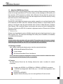
1.1 About the 54M Wireless Router
54M Wireless Router is a hybrid design product which combines Ethernet technology and wireless
access into a single stand-alone unit. The device allows you take advantages of both mobility and
fast connection. All PCs whenever on wireless LAN or Ethernet LAN can share files, printers and
other network resource. Moreover, all users can share single account of Internet access by having
this device connect to a DSL/Cable modem.
1. Ethernet / Fast Ethernet
Ethernet is the most widely-used network access method, especially in a Local Area.Network (LAN)
and is defined by the IEEE as the 802.3 standard. Normally, Ethernet is a shared media LAN. All
stations on the segment share the total bandwidth, which could be 10 Mbps (Ethernet), 100 Mbps
(Fast Ethernet). With a switched Ethernet, each sender and receiver has the full bandwidth.Fast
Ethernet is defined by the IEEE 802.3u standard, a high-speed version of Ethernet with 100 Mbps
transmission rate.
2. Wireless LAN
Wireless Local Area Network systems (WLANs) transmit and receive data through the air by using
radio frequency (RF). This offers some advantages like mobility, ease of installation, and scalability
over traditional wired systems.
Mobility:
WLANs combine data connectivity with user mobility. This provides users with access to network
anywhere in their organization. For example, users can roam from a conference room to their office
without being disconnected from the LAN. This is impossible with wired networks.
1.2 Package contents
After carefully unpacking the shipping carton, check the contents listed below.
54M Wireless Broadband Router Router
A power adapter
54M Wireless Broadband Router User Manual
If any of the listed contents are damaged or missing, please contact the retailer from whom
you purchased the 54M Wireless Router for assistance.
1.3 Features
The 54M Wireless Router has the following features that make it excellent for network
connections.
Complies with IEEE802.11g, IEEE802.11b, IEEE802.3, IEEE802.3u standards
1 10/100M Auto-Negotiation WAN RJ45 port, 4 10/100M Auto-Negotiation LAN
RJ45 ports
Supports Auto MDI/MDIX
Supports Wireless Roaming, can move among different AP and no break
-2-
Supports 54/48/36/24/18/12/9/6/11/5.5/3/2/1Mbps wireless LAN data transfer rates
Provides 64/128 bit WEP encryption security
Supports wireless mode: AP and Bridge
Provides WPA and WPA2 authentication and TKIP/AES encryption security
Provides wireless LAN ACL (Access Control List) filtering
Built-in NAT and DHCP server supporting static IP address distributing
Supports Virtual Server, Special Application, and DMZ host
Built-in firewall supporting IP address filtering, Domain Name filtering, and MAC
address filtering
Supports TCP/IP, PPPoE, DHCP, ICMP, NAT
Supports UPnP, Dynamic DNS
Supports Flow Statistics
Supports ICMP-FLOOD, UDP-FLOOD, TCP-SYN-FLOOD filter
Supports firmware upgrade
Supports Remote and Web management
S
Seeccttiio
on
nT
Tw
wo
oH
Haarrd
dw
waarree IIn
nssttaallllaattiio
on
n
2.1 Panel Layout
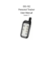
2.1.1 The Front Panel
The front panel of the 54M Wireless Router consists of several LED indicators, which is
designed to indicate connections. Viewed from left to right. The table describes the LEDs on
the front panel of the router.
Name
Power
CPU
Action
Description
OFF
No Power
ON
Power on
ON
The router is initialising
Flashing
The router is working properly
-3-
WL
1/2/3/4
OFF
The router has a hardware error
OFF
The Wireless Radio function is disabled
Flashing
The Wireless Radio function is enabled
OFF
There is no device linked to the corresponding port
ON
There is a device linked to the corresponding port but no
activity
Flashing
There is an active device linked to the corresponding port
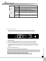
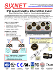
2.1.2 The Rear Panel
The rear panel contains the following features. (Viewed from left to right:)
1.
2.
3.
4.
Wireless antenna
WAN RJ45 port for connecting the router to a cable, DSL modem or Ethernet
Four LAN 10/100Mbps RJ45 ports for connecting the router to the local PCs
AC power socket: only use the power adapter supplied with the 54M WIRELESS
ROUTER 54Mbps Wireless Router, use of a different adapter may result in product
damage.
5. Factory Default Reset button
There is a way to reset the router's factory defaults
1.Use the Factory Default Reset button: First, turn on the router's power. Second, press
and hold the default reset button, until the system LED lights up(about 5 seconds). Last,
release the reset button and wait for the router to reboot.
Notice: Ensure the router is powered on before it restarts completely.
-4-
2.2 System Requirements
Broadband Internet Access Service (DSL/Cable/Ethernet)
One DSL/Cable modem that has an RJ45 connector (you do not need
it if you connect the router to Ethernet)
Each PC on the LAN needs a working Ethernet Adapter and an Ethernet cable with
RJ45 connectors
TCP/IP protocol must be installed on each PC
Web browser, such as Microsoft Internet Explorer 5.0 or later, Netscape Navigator
6.0 or later
2.3 Installation Environment Requirements
Not in direct sunlight or near a heater or heating vent
Not cluttered or crowded. There should be at least 2 inches (5 cm) of clear space on
all sides of the router
Well ventilated (especially if it is in a closet)
Operating temperature: 0 ~40
Operating Humidity: 5%~90%RH, Non-condensing
2.4 Connecting the Router
Before you install the router, you should connect your PC to the Internet through your
broadband service successfully. If there is any problem, please contact your ISP. After that,
please install the router according to the following steps. Don't forget to pull out the power
plug and keep your hands dry.
Power off your PC(s), Cable/DSL modem, and the router.
Locate an optimum location for the router. The best place is usually near the center
of the area in which your PC(s) will wirelessly connect. The place must accord with
the Installation
Environment Requirements.
Adjust the direction of the antenna. Normally, upright is a good direction.
Connect the PC(s) and each Switch/Hub on your LAN to the LAN Ports on the
router.
Connect the DSL/Cable Modem to the WAN port on the router.
Connect the AC power adapter to the AC power socket on the router, and the other
end into an electrical outlet. The router will start to work automatically.
Power on your PC(s) and Cable/DSL modem.
-5-
S
Seeccttiioonn TThhrreeee:: Q
Quuiicckk IInnssttaallllaattiioonn G
Guuiiddee
After connecting the 54M Wireless Router into your network, you should configure it. This
chapter
describes
how
to
configure
the
basic
functions
of
your
54M
Wireless Router. These procedures only take you a few minutes. You can access the
Internet via the router immediately after successfully configured.
3.1 TCP/IP configuration
The default IP address of the 54Mbps Wireless Router is 192.168.1.254, and the default
Subnet Mask is 255.255.255.0. These values can be seen from the LAN. They can
be changed as you desire, as an example we use the default values for description in this
guide.
Connect the local PCs to the LAN ports on the router. There are then two means to
configure the IP address for your PCs.
Configure the IP address manually
1. Set up the TCP/IP Protocol for your PC(s). If you need instructions as to how to do this.
2.Configure the network parameters. The IP address is 192.168.1.xxx ("xxx" is from 2 to
254), Subnet Mask is 255.255.255.0, and Gateway is 192.168.1.254(The router's
default IP address)
Obtain an IP address automatically
1.Set up the TCP/IP Protocol in "Obtain an IP address automatically" mode on your
PC(s). If you need instructions as to how to do this,
2.Power off the router and PC(s). Then turn on the router, and restart the PC(s). The built-in
DHCP server will assign IP addresses for the PC(s).
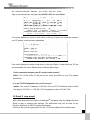
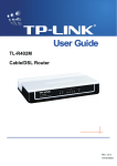
Now, you can run the Ping command in the command prompt to verify
-6-
the network connection between your PC(s) and the router.
Open a command prompt, and type ping 192.168.1.254, then press Enter.
If the result displayed is similar to that shown in the top of figure, the connection between
your PC and the router has been established.
If the result displayed is similar to that shown in the top of figure, it means that your PC has
not connected to the router. Please check it following these steps:
1. Is the connection between your PC and the router correct?
Notice: The 1/2/3/4 LEDs of LAN port on the router and LEDs on your PC's adapter
should be lit.
2. Is the TCP/IP configuration for your PC correct?
Notice: If the router's IP address is 192.168.1.254, your PC's IP address must be within
the range of 192.168.1.2 ~ 192.168.1.253, the gateway must be 192.168.1.254
3.2 Quick S etup wizard
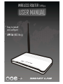
With a Web-based (Internet Explorer or Netscape® Navigator) utility, the 54Mbps Wireless
Router is easy to configure and manage. The Web-based utility can be used on any
Windows, Macintosh or UNIX OS with a web browser.
Connect to the router by typing http://192.168.1.254 in the address field of web browser.
-7-
After a moment, a login window will appear similar to that shown in Figure. Enter admin
for the User Name and Password, both in lower case letters. Then click the OK button or
press the Enter key.
NOTE:
IfConfigure
the above
does manually
not prompt, it means that your web-browser has been set to a
thescreen
IP address
proxy. Go to Tools menu>Internet Options>Connections>LAN Settings, in the screen that
appears, cancel the Using Proxy checkbox, and click OK to finish it.
If theClick
UserSetupWizard,
Name and Password
are correct,
can configure the router using the
the SetupWizard
will you
appear.
web browser. Please click the Setup Wizard link on the left of the main menu and
the Setup Wizard screen will appear.
-8-
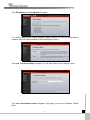
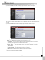
Click SetupWizard, the SetupWizard will appear.
The router supports three modes: gateway, bridge, wireless ISP. You can setup different
modes to LAN and WLAN interface for NAT and bridging function.
Click next, Time Zone Setting will appear. You can select the time zone what you need.
Click next, LAN Interface setup will appear. In this page, you can set IP address, Subnet
Mask.
-9-
IP Address - Enter the IP address of your router in dotted-decimal notation (factory default:
192.168.1.254).
Subnet Mask - An address code that determines the size of the network. Normally use
255.255.255.0 as the subnet mask.
Notice : The same to all PCs’ Subnet Mask with router in you LAN.
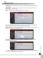
Click next, WAN Interface will appear. In this page is used to configure the parameters for
Internet network which connects to the WAN port of your Access Point.
WAN Access Type: Here you can select the access method to static IP, DHCP, PPPoE or
PPTP by click the item value of WAN Access type.
User Name and Password - Enter the User Name and Password provided by your ISP.
Services name: Default is blank.
If you choose " DHCP Client", the router will automatically receive the IP parameters from
your ISP without needing to enter any parameters.
- 10 -
If you Choose "PPTP", the Static IP settings page will appear, shown in the figure.
You can get IP Address Subnet Mask, server IP Address, User Name and Password from
your ISP
If you Choose "Static IP", the Static IP settings page will appear, shown in figure.
Note: The IP parameters should have been provided by your ISP.
IP Address - This is the WAN IP address as seen by external users on the Internet
(including your ISP). Enter the IP address into the field.
Subnet Mask -
The Subnet Mask is used for the WAN IP address, it is usually
255.255.255.0
Default Gateway - Enter the gateway into the box if required.
DNS - Enter the DNS Server IP address into the boxes if required.
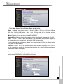
Click next, wireless basic setting will appear.
- 11 -
This page is used to configure these parameters
Band - Indicates the current mode (2.4GHz(G)-54Mbps (802.11g), 2.4GHz(B)11Mbps
(802.11b)). 2.4GHz(G+B), which allows both 802.11g and 802.11b wireless stations
to connect to the router.
Mode-Default is AP,you can select Client,WDS,AP+WDS
Network Type-Default is Infrastructure,when mode is client,Network Type may be AD-HOC
SSID - Enter a value of up to 32 characters. The same name (SSID) must be ssigned to
all wireless devices in your network. The default SSID is Kingnet, but
it is recommended strongly that you change your networks name (SSID) to a different value.
This value is case-sensitive.
Channel – Fro m 1 to 13.This field determines which operating frequency will be used. It
is not necessary to change the wireless channel unless you notice interference problems
with another nearby access point.
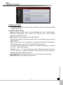
Click next, Wirelss Security Setup will appear.this page allow you setuo the security. You can
select NoneWEP WPA(TKIP),WPA2(AES),WPA2 Mixed.
- 12 -
Click Apply Changes,you will find the page show set secceful.
Notice: If you change the parameters of wireless, The router will reboot automatically.
3.3 Operation mode
Gateway (default) In this mode, the device is supposed to connect to internet via ADSL/Cable
Modem. The NAT is enabled and PCs in LAN ports share the same IP to ISP through WAN port.
The connection type can be setup in WAN page by using PPPOE, DHCP client, PPTP client or
static IP.
Bridge: In this mode, all ethernet ports and wireless interface are bridged together and NAT
function is disabled. All the WAN related function and firewall are not supported.
S
Seeccttiio
on
n ffo
ou
urr C
Co
on
nffiig
gu
urraattiio
on
nG
Gu
uiid
dee
4.1 Login
After you login successful, Browser will show administrator WEB. on the left is contents. it
contains: Wireless setting, WAN Settings, LAN Settings, Network Security, System Services,
Management, Status Show, Exit Setting.
- 13 -
4.2 Wireless Setting
it contains Wireless Basic settings, Advance Settings, security, Access Control, WDS
Settings, Site Survey.
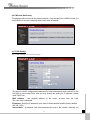
4.2.1 Wireless Basic settings
Band: Indicates the current mode (2.4GHz(G)-54Mbps (802.11g), 2.4GHz(B)11Mbps
(802.11b)). 2.4GHz(G+B), which allows both 802.11g and 802.11b wireless
stations to connect to the router.
Mode: Default is AP,you can select Client,WDS,AP+WDS
Network Type: Default is Infrastructure,when mode is client,Network Type should be
setting AD-HOC
SSID: Enter a value of up to 32 characters. The same name (SSID) must bessigned to
all wireless devices in your network. The default SSID is Kingnet, but
It is recommended strongly that you change your networks name (SSID) to a different
value. This value is case-sensitive.
Channel: Fro m 1 to 1 3.This field determines which operating frequency will be used.
It is not necessary to change the wireless channel unless you notice interference
problems with another nearby access point.
Associated Client: click show active client, you can check the list of wireless client.
Enable MAC Clone: it only adapt to wireless client.
- 14 -
4.2.2 Wireless Advanced Settings
These settings are only for more technically advanced users who have a sufficient
knowledge about wireless LAN. These settings should not be changed unless you know
what effect the changes will have on your Access Point.
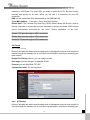
4.2.3 Wireless security setup
This page allows you setup the wireless security. Turn on WEP or WPA by using Encryption
Keys could prevent any unauthorized access to your wireless network.
- 15 -
Encryption: you can select None,WEP,WPA,WPA2, WPA2 Mixed
WEP:Wired Equivalent Protoco.
WPA:(WI-FI Protected Access Wi-Fi) WPA is an intermediate solution for the security issues. It
uses Temporal Key Integrity Protocol (TKIP) to replace WEP.
TKIP: TKIP is a compromise on strong security and possibility to use existing hardware. It still
uses RC4 for the encryption like WEP, but with per-packet RC4 keys. In addition, it implements
replay protection, keyed packet authentication mechanism (Michael MIC).
WPA Authentication Mode: Keys can be managed using two different mechanisms. WPA
can either use an external authentication server (e.g., RADIUS) and EAP just like IEEE 802.1X
is using or pre-shared keys without need for additional servers. Wi-Fi calls these
"WPA-Enterprise" and "WPA-Personal", respectively. Both mechanisms will generate a master
session key for the Authenticator (AP) and Supplicant (client station).
802.1X: The original security mechanism of IEEE 802.11 standard was not designed to be
strong and has proven to be insufficient for most networks that require some kind of security.
Task group I (Security) of IEEE 802.11 working group has worked to address the flaws of the
base standard and in practice completed its work in May 2004. The IEEE 802.11i amendment
to the IEEE 802.11 standard was approved in June 2004 and published in July 2004.
WPA Cipher suite/WPA2 Cipher suite:The encryption piece of WPA and WPA2 mandates
the use of TKIP or, because it's considered to be more secure than TKIP, preferably AES
encryption.
Pre-Shared Key Format: You can select PASSPHRASE or HEX(64 CHARACTERS).
Pre-Shared Key: You can input 128 characters key.
Authentication RADIUS Server:input Port and IP Address and Password.
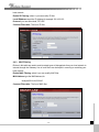
4.2.4 Wireless Access Control
If you choose 'Allowed Listed', only those clients whose wireless MAC addresses are in the
access control list will be able to connect to your Access Point. When 'Deny Listed' is selected,
these wireless clients on the list will not be able to connect the Access Point.
- 16 -
4.2.5 Wireless Site Survey
This page provides tool to scan the wireless network. If any Access Point or IBSS is found, you
could choose to connect it manually when client mode is enabled.
4.3 TCP/IP Setting
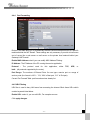
4.3.1 LAN Setting Lan Interface setup
This page is used to configure the parameters for local area network which connects to the
LAN port of your Access Point. Here you may change the setting for IP addresss, subnet
mask, DHCP, etc..
MAC Address - the physical address of the router, as seen from the LAN.
The value can't be changed.
IP Address - Enter the IP address of your router in dotted-decimal notation (factory default:
192.168.1.254).
Subnet Mask - An address code that determines the size of the network. Normally use
- 17 -
255.255.255.0 as the subnet mask.
DHCP: You can select None,Client,Serve. The router is set up by default as a DHCP
(Dynamic Host Configuration Protocol) server, which provides the TCP/IP configuration for
all the PCs that are connected to the router on the LAN.
DHCP Client Range: This field specifies the first of the addresses in the IP address pool.
802.1d Spanning Tree: The IEEE 802.1D Spanning Tree Algorithm (STA) ,loop prevention
and redundant link configuration. You can select disable or enable.if your mode was set
WDS or AP+WDS, this item should be set “enable”
Clone MAC Address:you can enter a MAC,Then click clone.
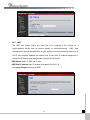
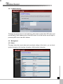
4.3.2WAN Interface
This
page is used to configure the parameters for Internet network which connects to the WAN
port of your Access Point. Here you may change the access method to static IP, DHCP,
PPPoE or PPTP by click the item value of WAN Access type.
WAN Access Type,User name, password, Service:
you can refer to 3.2 Quick Installation Guide.
Connection Type:you can select continous o, connect on demand, manual.
Idle time: when connection type is connect on demand,you can set idle time.
MTU Size: The normal MTU (Maximum Transmission Unit) value for most Ethernet
- 18 -
networks is 1492 Bytes. For some ISPs you need to reduce the MTU. But this is rarely
required, and should not be done unless you are sure it is necessary for your ISP
connection.
DNS:You can select Attain DNS Automatically or Set DNS Manually
Clone MAC Address: if you wang clone, input MAC Address
Enable UpnP: The Universal Plug and Play (UPnP) feature allows the devices, such as
Internet computers, to access the local host resources or devices as needed. UPnP devices
can be
automatically discovered by
the
UPnP
service
application
on the LAN.
Enable L2TP pass through on VPN connection:
Enable IPsec pass through on VPN connection:
Enable PPTP pass through on VPN connection:
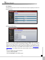
4.4 Firewal
4.4.1 Port Filtering
Entries in this table are used to restrict certain types of data packets from your local network to
Internet through the Gateway. Use of such filters can be helpful in securing or restricting your
local network.
Enable Port filtering: select it, you can modify port filter.
Port range: input the filter port, for eaample 20-220
Protocol: you can select both,TCP,UDP
Cuurrent filter table: The list of port filter.
4.4.2
IP Filtering
Entries in this table are used to restrict certain types of data packets from your local network to
Internet through the Gateway. Use of such filters can be helpful in securing or restricting your
- 19 -
local network.
Enable IP Filtering: select it, you can modify IP filter.
Local IPAddress:input the IP Address,for example:192.168.1.23.
Protocol: you can select both,TCP,UDP
Cuurrent Filter table: The list of IP filter.
4.4.3
MAC Filtering
Entries in this table are used to restrict certain types of data packets from your local network to
Internet through the Gateway. Use of such filters can be helpful in securing or restricting your
local network
Enable MAC Filtering: select it,you can modify MAC filter.
MACAddress:type the MACAddress,for
example:00:e0:4e:3f:2d:c5.
Cuurrent Filter table: The list of MAC filter.
- 20 -
4.4.4
Port Forwarding
Entries in this table allow you to automatically redirect common network services to a specific
machine behind the NAT firewall. These settings are only necessary if you wish to host some
sort of server like a web server or mail server on the private local network behind your
Gateway's NAT firewall.
Enable MAC Address:select it,you can modify MAC Address Filtering..
IP Address: The IP Address of the PC running the service application
Protocol
both
-
The
protocol
used
for
this
application,
either
TCP,
UDP,
or
(all protocols supported by the router).
Port R a n g e - The numbers of External Ports. You can type a service port or a range of
service ports (the format is XXX – YYY, XXX is Start port, YYY is End port).
Current Port Forward Table: port forward services already list.
4.4.5 URL Filtering
URL filter is used to deny LAN users from accessing the internet. Block those URLs which
contain keywords listed below.
Enable URL : select it, you can edit URL, For example:xxx.com
Click apply changes.
- 21 -
4.4.6
DMZ
The DMZ host feature allows one local host to be exposed to the Internet for a
special-purpose service such as Internet gaming or videoconferencing.
DMZ
host
forwards all the ports at the same time. Any PC whose port is being forwarded must have its
DHCP client function disabled and should have a new static IP Address assigned to it
because its IP Address may change when using the DHCP function.
DMZ Enable: Select it, DMZ can be edit..
DMZ Host IP Address:input IP Address.for example 192.168.1.34.
Click apply changes,complete set DMZ.
- 22 -
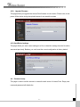
4.4.7 AntiARP Cheating
This page can set the device to send packets to other hosts to refresh their ARP cache, and
can add static IP-MAC address entry to local ARP cache. Use of this function can be helpful in
preventing ARP virus or fake MAC address
4.5
Management
4.5.1 Status
This page shows the current status and some basic settings of the device. you can check
system Information, LAN Interface Information, WAN Interface Information.
- 23 -
4.5.2 Statistics
This page shows the packet counters for transmission and reception regarding to wireless and
Ethernet networks.
4.5.3 Dynamic DNS Setting
Dynamic DNS is a service, that provides you with a valid, unchanging, internet domain name
(an URL) to go with that (possibly everchanging) IP-address. DDNS lets you assign a
fixed host and domain name to a dynamic Internet IP Address. It is useful when you are
hosting your own website, FTP server, or other server behind the router. Before using this
feature, you need to sign up for DDNS service providers such as www.oray.net or
www.comexe.cn. The Dynamic DNS client service provider will give you a password or
key.
To set up for DDNS, follow these instructions:
1.Type your dervice provider.
2.Type the User Name for your DDNS account.
- 24 -
3.Type the Password for your DDNS account.
4.Domain Name - the domain names are displayed here. Click Apply Changes to logout
the DDNS service.
4.5.5 Time Zone Setting
You can maintain the system time by synchronizing with a public time server over the
Internet.
Current time: type the date and time.
Time Zone Select: Select your local time zone from this pull down list.
Enable NTP client update:select it, you can get the time from NTP.
NTP server :select a server from list.
Click the Apply changes get the time from Internet if you have connected toInternet.
4.5. 6 Denial of Service
A "denial-of-service" (DoS) attack is characterized by an explicit attempt by hackers to prevent
legitimate users of a service from using that service.
Enable DOS Prevention:select it, you can modify DOS Prevention.
Enable Source IP Blocking: you can input source IP Blocking time
Click apply changes,DOS take effect.
- 25 -
4.5.7 Log
This page can be used to set remote log server and show the system log.
- 26 -
4.5.8
Upgrade Firmware
This page allows you upgrade the Access Point firmware to new version. Please note, do not
power off the device during the upload because it may crash the system
4.5.9 Save/Reload settings
This page allows you save current settings to a file or reload the settings from the file which
was saved previously. Besides, you could reset the current configuration to factory default.
4.6
Password setup
This page is used to set the account to access the web server of Access Point. Empty user
name and password will disable the
- 27 -
A
Appppeennddiixx 11:: FFA
AQ
Q
1. How do I configure the router to access Internet by ADSL users?
(1) First, configure the ADSL modem configured in RFC1483 bridge model.
(2) Connect the Ethernet cable from your ADSL modem to the WAN port on the router.
The telephone cord plugs into the Line port of the ADSL modem.
(3) Login to the router, click the “TCP/IP settings” menu on the left of your browser, and
click "WAN Interface" submenu. On the WAN page, select “PPPoE” for WAN
Connection Type. Type user name in the “User Name” field and password in the
“Password” field, finish by clicking “Connect”.
(4) If your ADSL lease is in “pay-according-time” mode, select “Connect on Demand” or
“Manual” for Internet connection mode. Type an appropriate number for Time
to avoid wasting paid time. Otherwise, you can select “continous” for Internet
connection mode.
2. How do I configure the router to access Internet by Ethernet users?
(1) Login to the router, click the “TCP/IP Settings” menu on the left of your browser, and
click "LAN Interface" submenu. On the WAN page, select “DHCP” for "Client", finish by
clicking “apply changes”.
(2) Some ISPs require that you register the MAC Address of your adapter, which is
connected to your cable or DSL modem during installation. If your ISP requires MAC
register, login to the router and click the "TCP/IP Setting" menu link on the left of your
browser, and then click "LAN Interface", if your PC’s MAC address is proper MAC
address,type your PC’s MAC address will fill in the "Clone MAC Address" field. Or
else,The format for the MAC Address isXX-XX-XX-XX-XX-XX. Then click the
"apply changes" button. It will take effect after rebooting.
3. I want to use Netmeeting, what do I need to do?
(1) If you start Netmeeting as a sponsor, you don’t need to do anything with the router.
- 28 -
(2) If you start as a responsor, you need configure Virtual Server or DMZ Host.
(3) How to configure Virtual Server: Login to the router, click the “Forwarding” menu on the
left of your browser, and click " port foward" submenu. On the "port forward " page, enter
“1720” into the blank below the “Service Port”, and your IP address below the IP
Address, assuming 192.168.1.25469 for an example, remember to “supply
changes”.
(4) How to enable DMZ Host: Login to the router, click the “firewall settings” menu on the
left of your browser, and click " DMZ" submenu. On the "DMZ" page, click “Enable DMZ”
radio and type your IP address into the “DMZ Host IP Address” field, using
192.168.1.25469 as an example, remember to click the "Apply changes” button.
4. The wireless stations cannot connect to the router.
(1) Make sure the "Disable Wireless LAN Interface " is not select.
(2) Make sure that the wireless stations' SSID accord with the router's SSID.
(3)
Make sure the wireless stations have right KEY for encryption when the router is
encrypted.
(4) If the wireless connection is ready, but you can’t access the router, check the IP
Address of your wireless stations.
A
Appppeennddiixx 22:: S
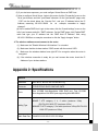
Sppeecciiffiiccaattiioonnss
General
Standards
IEEE 802.3, 802.3u, 802.11b and 802.11g
Protocols
TCP/IP, PPPoE, DHCP, ICMP, NAT, SNTP
Ports
One 10/100M Auto-Negotiation WAN RJ45 port, Four 10/100M
Auto-Negotiation LAN RJ45 ports supporting Auto MDI/MDIX
10BASE-T :UTP category 3, 4, 5 cable (maximum 100m)
Cabling Type
EIA/TIA-568 100Ω STP (maximum 100m)
100BASE-TX:UTP category 5, 5e cable (maximum 100m) EIA/TIA-568
100Ω STP (maximum 100m)
Radio Data Rae
54/48/36/24/18/12/9/6/11/5.5/3/2/1Mbps
- 29 -
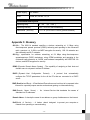
Power Supply
9V~ 800mA
LEDs
Power, M1, WLAN, 1,2,3,4
Environmental and Physical
Operating Temp.
0 ~40
Operating Humidity
10% - 95% RH, Non-condensing
Dimensions (W×D×H)
(32 ~104 )
4.7×1.2 in. (201×120×31.10 mm) (without antenna)
Appendix 3: Glossary
802.11b - The 802.11b standard specifies a wireless networking at 11 Mbps using
direct-sequence spread- spectrum (DSSS) technolog and operating in the unlicensed
radio spectrum at 2.4GHz, and WEP encryption for security. 802.11b networks are
also referred to as Wi-Fi networks.
802.11g - specification for wireless networking at 54 Mbps using direct-sequence
spread-spectrum (DSSS) technology, using OFDM modulation and operating in the
unlicensed radio spectrum at 2.4GHz, and backward compatibility with IEEE 802.11b
devices, and WEP encryption for security.
DDNS (Dynamic Domain Name System) - The capability of assigning a fixed host and
domain name to a dynamic Internet IP Address.
DHCP. (Dynamic Host Configuration Protocol) - A protocol that automatically
configure the TCP/IP parameters for the all the PCs that are connected to a DHCP
server.
DMZ.(Demilitarized Zone) - A Demilitarized Zone allows one local host to be exposed tothe
Internet for a special-purpose service such anternet gaming or videoconferencing.
DNS.(Domain Name Server)
websites into IP addresses.
-
An
Internet Service that translates the names of
Domain Name - A descriptive name for an address or group of addresses on the Internet.
DoS(Denial of Service) - A hacker attack designed to prevent your computer or
network from operating or communicating.
- 30 -
DSL(Digital Subscriber Line) - A technology that allows data to be sent or received over
existing traditional phone lines.
ISP(Internet Service Provider) - A company that provides access to the Internet
MTU (Maximum Transmission Unit) - The size in bytes of the largest packet that can be
transmitted.
NAT(Network Address Translation) - NAT technology translates IP addresses of a local area
network to a different IP address for the Internet.
PPPoE (Point to Point Protocol over Ethernet) - PPPoE is a protocol for connecting remote
hosts to the Internet over an always-on connection by simulating a dial-up connection.
SSID - A Service Set Identification is a thirty-two character (maximum) alphanumeric key
identifying a wireless local area network. For the wireless devices in a network to
communicate with each other, all devices must be configured with the same SSID. This
is typically the configuration parameter for a wireless PC card. It corresponds to the
ESSID in the wireless Access Point and to the wireless network name.
WEP (Wired Equivalent Privacy) - A data privacy mechanism based on a 64-bit or
128-bit or 152-bit shared key algorithm, as described in the IEEE 802.11 standard.
Wi-Fi - A trade name for the 802.11b wireless networking standard, given by the
Wireless Ethernet Compatibility Alliance (WECA, see http://www.wi-fi.net), an industry
standards group promoting interoperability among 802.11b devices.
WLAN (Wireless Local Area Network) - A group of computers and associated devices
communicate with each other wirelessly, which network serving users are
limited in a local area.
- 31 -
- 32 -