1
TimeSource 3500
GPS Primary Reference Source
User’s Guide
Revision M – October 2007
Part Number 097-72050-01
Symmetricom, Inc.
2300 Orchard Parkway
San Jose, CA 95131-1017
U.S.A.
http://www.symmetricom.com
Copyright © 1999–2006 Symmetricom, Inc.
All rights reserved. Printed in U.S.A.
All product names, service marks, trademarks, and registered trademarks
used in this document are the property of their respective owners.
Contents
How to Use This Guide
Purpose of This Guide . . . . . . . . . . . . . . . . . . . . . . . . . . . . . . . . . . . . . . . . . . .14
Who Should Read This Guide. . . . . . . . . . . . . . . . . . . . . . . . . . . . . . . . . . . . . .14
Structure of This Guide . . . . . . . . . . . . . . . . . . . . . . . . . . . . . . . . . . . . . . . . . . .14
Conventions Used in This Guide. . . . . . . . . . . . . . . . . . . . . . . . . . . . . . . . . . . .15
Warnings, Cautions, Recommendations, and Notes . . . . . . . . . . . . . . . . . . . .16
Related Documents and Information. . . . . . . . . . . . . . . . . . . . . . . . . . . . . . . . .17
Where to Find Answers to Product and Document Questions . . . . . . . . . . . . .17
What’s New In This Guide. . . . . . . . . . . . . . . . . . . . . . . . . . . . . . . . . . . . . . . . .17
Chapter 1
Description
Overview . . . . . . . . . . . . . . . . . . . . . . . . . . . . . . . . . . . . . . . . . . . . . . . . . . . . . .20
Global Positioning System . . . . . . . . . . . . . . . . . . . . . . . . . . . . . . . . . . . . . . . .21
Physical Description . . . . . . . . . . . . . . . . . . . . . . . . . . . . . . . . . . . . . . . . . . . . .21
Roof Antenna . . . . . . . . . . . . . . . . . . . . . . . . . . . . . . . . . . . . . . . . . . . . . .22
Mechanical Window Antenna . . . . . . . . . . . . . . . . . . . . . . . . . . . . . . . . . .22
Self-Adhesive Window Antenna . . . . . . . . . . . . . . . . . . . . . . . . . . . . . . . .23
Wall Antenna. . . . . . . . . . . . . . . . . . . . . . . . . . . . . . . . . . . . . . . . . . . . . . .24
097-72050-01 Revision M – October, 2007
TimeSource 3500 User’s Guide
3
Table of Contents
Functional Description. . . . . . . . . . . . . . . . . . . . . . . . . . . . . . . . . . . . . . . . . . . .24
Overview . . . . . . . . . . . . . . . . . . . . . . . . . . . . . . . . . . . . . . . . . . . . . . . . . .24
Antenna. . . . . . . . . . . . . . . . . . . . . . . . . . . . . . . . . . . . . . . . . . . . . . . . . . .26
IF Interface . . . . . . . . . . . . . . . . . . . . . . . . . . . . . . . . . . . . . . . . . . . . . . . .27
GPS Receiver . . . . . . . . . . . . . . . . . . . . . . . . . . . . . . . . . . . . . . . . . . . . . .27
Local Oscillator . . . . . . . . . . . . . . . . . . . . . . . . . . . . . . . . . . . . . . . . . . . . .27
Clock Extractors . . . . . . . . . . . . . . . . . . . . . . . . . . . . . . . . . . . . . . . . . . . .28
Power Supply . . . . . . . . . . . . . . . . . . . . . . . . . . . . . . . . . . . . . . . . . . . . . .28
NTP TimeServer . . . . . . . . . . . . . . . . . . . . . . . . . . . . . . . . . . . . . . . . . . . .28
Network Time Protocol Password Activation . . . . . . . . . . . . . . . . . . . . . .28
BesTime Ensemble Timing Generator . . . . . . . . . . . . . . . . . . . . . . . . . . .28
Eight Mixed T1/E1/2.048 MHz Outputs (990-72050-06 Systems Only) . .29
Eight Mixed T1/CCK Outputs (990-72050-07 Systems Only) . . . . . . . . . .29
T1 Outputs . . . . . . . . . . . . . . . . . . . . . . . . . . . . . . . . . . . . . . . . . . . . . . . .29
Additional T1 Outputs (990-72050-02 Systems Only) . . . . . . . . . . . . . . .29
TOD Output. . . . . . . . . . . . . . . . . . . . . . . . . . . . . . . . . . . . . . . . . . . . . . . .29
IRIG-B TOD Outputs (990-72050-05 Systems Only) . . . . . . . . . . . . . . . .29
1 PPS Output . . . . . . . . . . . . . . . . . . . . . . . . . . . . . . . . . . . . . . . . . . . . . .30
10 MHz Output . . . . . . . . . . . . . . . . . . . . . . . . . . . . . . . . . . . . . . . . . . . . .30
Composite Clock Outputs
(990-72050-03 Systems Only) . . . . . . . . . . . . . . . . . . . . . . . . . . . . . . . . .30
Alarm Interface . . . . . . . . . . . . . . . . . . . . . . . . . . . . . . . . . . . . . . . . . . . . .30
Communication Ports . . . . . . . . . . . . . . . . . . . . . . . . . . . . . . . . . . . . . . . .30
Ethernet . . . . . . . . . . . . . . . . . . . . . . . . . . . . . . . . . . . . . . . . . . . . . . . . . .30
Passthrough . . . . . . . . . . . . . . . . . . . . . . . . . . . . . . . . . . . . . . . . . . . . . . .31
Alarm Programmability . . . . . . . . . . . . . . . . . . . . . . . . . . . . . . . . . . . . . . .31
Startup . . . . . . . . . . . . . . . . . . . . . . . . . . . . . . . . . . . . . . . . . . . . . . . . . . .32
Bridging/Holdover Behavior . . . . . . . . . . . . . . . . . . . . . . . . . . . . . . . . . . .33
Time Figure of Merit . . . . . . . . . . . . . . . . . . . . . . . . . . . . . . . . . . . . . . . . .34
Success Rate . . . . . . . . . . . . . . . . . . . . . . . . . . . . . . . . . . . . . . . . . . . . . .35
Chapter 2
Engineering and Ordering
Antenna Guidelines. . . . . . . . . . . . . . . . . . . . . . . . . . . . . . . . . . . . . . . . . . . . . .38
Site Survey . . . . . . . . . . . . . . . . . . . . . . . . . . . . . . . . . . . . . . . . . . . . . . . .38
Roof Antenna Location and Cabling Guidelines . . . . . . . . . . . . . . . . . . . .38
Roof Antenna Earth Ground Location Guidelines. . . . . . . . . . . . . . . . . . .42
Roof Antenna Cable Choices . . . . . . . . . . . . . . . . . . . . . . . . . . . . . . . . . .42
Window and Wall Antenna Location Guidelines . . . . . . . . . . . . . . . . . . . .43
Window and Wall Antenna Cable Choices . . . . . . . . . . . . . . . . . . . . . . . .44
IRIG-B TOD (990-72050-05 System Only) . . . . . . . . . . . . . . . . . . . . . . . .45
RJ-422–to–RS-232 TOD Converter . . . . . . . . . . . . . . . . . . . . . . . . . . . . .45
Shelf Considerations . . . . . . . . . . . . . . . . . . . . . . . . . . . . . . . . . . . . . . . . . . . . .45
4
TimeSource 3500 User’s Guide
097-72050-01 Revision M – October, 2007
Table of Contents
Systems . . . . . . . . . . . . . . . . . . . . . . . . . . . . . . . . . . . . . . . . . . . . . . . . . . . . . .46
Standard System (Two T1 Outputs) . . . . . . . . . . . . . . . . . . . . . . . . . . . . .46
With Eight Additional T1 Outputs . . . . . . . . . . . . . . . . . . . . . . . . . . . . . . .47
With Eight Additional Mixed E1/T1 Outputs . . . . . . . . . . . . . . . . . . . . . . .47
With Eight Additional Mixed T1/CCK Outputs. . . . . . . . . . . . . . . . . . . . . .47
With Eight Composite Clock Outputs . . . . . . . . . . . . . . . . . . . . . . . . . . . .48
With Two IRIG-B TOD Outputs. . . . . . . . . . . . . . . . . . . . . . . . . . . . . . . . .48
Antennas . . . . . . . . . . . . . . . . . . . . . . . . . . . . . . . . . . . . . . . . . . . . . . . . . . . . . .48
Roof Antenna . . . . . . . . . . . . . . . . . . . . . . . . . . . . . . . . . . . . . . . . . . . . . .48
Mechanical Window Antenna . . . . . . . . . . . . . . . . . . . . . . . . . . . . . . . . . .49
Self-Adhesive Window Antenna . . . . . . . . . . . . . . . . . . . . . . . . . . . . . . . .49
Wall Antenna. . . . . . . . . . . . . . . . . . . . . . . . . . . . . . . . . . . . . . . . . . . . . . .49
Optional Wall Antenna Lightning Suppressors . . . . . . . . . . . . . . . . . . . . .50
User-Supplied Tools and Materials . . . . . . . . . . . . . . . . . . . . . . . . . . . . . . . . . .50
For Roof Antenna Installation . . . . . . . . . . . . . . . . . . . . . . . . . . . . . . . . . .51
For Mechanical Window Antenna Installation . . . . . . . . . . . . . . . . . . . . . .51
For Self-Adhesive Window Antenna Installation . . . . . . . . . . . . . . . . . . . .51
For Wall Antenna Installation . . . . . . . . . . . . . . . . . . . . . . . . . . . . . . . . . .52
For Shelf Installation . . . . . . . . . . . . . . . . . . . . . . . . . . . . . . . . . . . . . . . . .52
Outputs, Power, and Miscellaneous . . . . . . . . . . . . . . . . . . . . . . . . . . . . .52
Chapter 3
Installation
Unpacking . . . . . . . . . . . . . . . . . . . . . . . . . . . . . . . . . . . . . . . . . . . . . . . . . . . . .54
Antenna. . . . . . . . . . . . . . . . . . . . . . . . . . . . . . . . . . . . . . . . . . . . . . . . . . . . . . .54
Roof Antenna . . . . . . . . . . . . . . . . . . . . . . . . . . . . . . . . . . . . . . . . . . . . . .54
Roof Antenna Mounting and Cable Connection Procedure . . . . . . . . . . .56
Mechanical Window Antenna Mounting and
Cable Connection Procedure . . . . . . . . . . . . . . . . . . . . . . . . . . . . . . . . . .59
Self-Adhesive Window Antenna . . . . . . . . . . . . . . . . . . . . . . . . . . . . . . . .61
Self-Adhesive Window Antenna Mounting and
Cable Connection Procedure . . . . . . . . . . . . . . . . . . . . . . . . . . . . . . . . . .61
Wall Antenna. . . . . . . . . . . . . . . . . . . . . . . . . . . . . . . . . . . . . . . . . . . . . . .63
Wall Antenna Installation Procedure. . . . . . . . . . . . . . . . . . . . . . . . . . . . .64
Shelf . . . . . . . . . . . . . . . . . . . . . . . . . . . . . . . . . . . . . . . . . . . . . . . . . . . . . . . . .68
Rack Mounting . . . . . . . . . . . . . . . . . . . . . . . . . . . . . . . . . . . . . . . . . . . . .68
Power and Signal Cabling. . . . . . . . . . . . . . . . . . . . . . . . . . . . . . . . . . . . .69
IRIG-B TOD Output Installation Procedure. . . . . . . . . . . . . . . . . . . . . . . .74
RS-422–to–RS-232 TOD Converter Installation Procedure . . . . . . . . . . .77
Power-Up . . . . . . . . . . . . . . . . . . . . . . . . . . . . . . . . . . . . . . . . . . . . . . . . . . . . .81
Power-Up Procedure . . . . . . . . . . . . . . . . . . . . . . . . . . . . . . . . . . . . . . . .81
097-72050-01 Revision M – October, 2007
TimeSource 3500 User’s Guide
5
Table of Contents
Installing the Firmware . . . . . . . . . . . . . . . . . . . . . . . . . . . . . . . . . . . . . . . . . . .91
Estimated Installation Time. . . . . . . . . . . . . . . . . . . . . . . . . . . . . . . . . . . .91
Requirements . . . . . . . . . . . . . . . . . . . . . . . . . . . . . . . . . . . . . . . . . . . . . .91
Hardware . . . . . . . . . . . . . . . . . . . . . . . . . . . . . . . . . . . . . . . . . . . . . . . . .92
Software . . . . . . . . . . . . . . . . . . . . . . . . . . . . . . . . . . . . . . . . . . . . . . . . . .92
Installing Firmware Manually. . . . . . . . . . . . . . . . . . . . . . . . . . . . . . . . . . . . . . .92
Installing Firmware with TimeWizard . . . . . . . . . . . . . . . . . . . . . . . . . . . . . . . .96
TimeWizard Installation and Operation. . . . . . . . . . . . . . . . . . . . . . . . . . .96
Factory-Set Values . . . . . . . . . . . . . . . . . . . . . . . . . . . . . . . . . . . . . . . . . . . . .106
Chapter 4
TL1 Reference
Conventions . . . . . . . . . . . . . . . . . . . . . . . . . . . . . . . . . . . . . . . . . . . . . . . . . .110
Command Format . . . . . . . . . . . . . . . . . . . . . . . . . . . . . . . . . . . . . . . . . . . . . .111
Response Format . . . . . . . . . . . . . . . . . . . . . . . . . . . . . . . . . . . . . . . . . . . . . .111
Parameters . . . . . . . . . . . . . . . . . . . . . . . . . . . . . . . . . . . . . . . . . . . . . . . . . . .112
Autonomous Messages. . . . . . . . . . . . . . . . . . . . . . . . . . . . . . . . . . . . . . . . . .115
Report Alarm. . . . . . . . . . . . . . . . . . . . . . . . . . . . . . . . . . . . . . . . . . . . . .115
Report Event . . . . . . . . . . . . . . . . . . . . . . . . . . . . . . . . . . . . . . . . . . . . . .116
Tasks/Commands . . . . . . . . . . . . . . . . . . . . . . . . . . . . . . . . . . . . . . . . . . . . . .116
6
TimeSource 3500 User’s Guide
097-72050-01 Revision M – October, 2007
Table of Contents
Commands . . . . . . . . . . . . . . . . . . . . . . . . . . . . . . . . . . . . . . . . . . . . . . . . . . .118
Activate User. . . . . . . . . . . . . . . . . . . . . . . . . . . . . . . . . . . . . . . . . . . . . .118
Cancel User . . . . . . . . . . . . . . . . . . . . . . . . . . . . . . . . . . . . . . . . . . . . . .118
Copy Memory . . . . . . . . . . . . . . . . . . . . . . . . . . . . . . . . . . . . . . . . . . . . .119
Delete Equipment . . . . . . . . . . . . . . . . . . . . . . . . . . . . . . . . . . . . . . . . . .121
Delete User Security . . . . . . . . . . . . . . . . . . . . . . . . . . . . . . . . . . . . . . . .121
Edit Communication . . . . . . . . . . . . . . . . . . . . . . . . . . . . . . . . . . . . . . . .122
Edit Date . . . . . . . . . . . . . . . . . . . . . . . . . . . . . . . . . . . . . . . . . . . . . . . . .125
Edit Equipment . . . . . . . . . . . . . . . . . . . . . . . . . . . . . . . . . . . . . . . . . . . .127
Enter Equipment . . . . . . . . . . . . . . . . . . . . . . . . . . . . . . . . . . . . . . . . . . .133
Enter User Security. . . . . . . . . . . . . . . . . . . . . . . . . . . . . . . . . . . . . . . . .134
Initialize Log . . . . . . . . . . . . . . . . . . . . . . . . . . . . . . . . . . . . . . . . . . . . . .134
Initialize Register. . . . . . . . . . . . . . . . . . . . . . . . . . . . . . . . . . . . . . . . . . .135
Initialize System . . . . . . . . . . . . . . . . . . . . . . . . . . . . . . . . . . . . . . . . . . .135
Operate Alarm Cutoff All . . . . . . . . . . . . . . . . . . . . . . . . . . . . . . . . . . . . .136
Retrieve Alarm All . . . . . . . . . . . . . . . . . . . . . . . . . . . . . . . . . . . . . . . . . .136
Retrieve Alarm Equipment . . . . . . . . . . . . . . . . . . . . . . . . . . . . . . . . . . .137
Retrieve Communication. . . . . . . . . . . . . . . . . . . . . . . . . . . . . . . . . . . . .137
Retrieve Condition All . . . . . . . . . . . . . . . . . . . . . . . . . . . . . . . . . . . . . . .140
Retrieve Condition Equipment . . . . . . . . . . . . . . . . . . . . . . . . . . . . . . . .140
Retrieve Equipment . . . . . . . . . . . . . . . . . . . . . . . . . . . . . . . . . . . . . . . .141
Retrieve GPS Status. . . . . . . . . . . . . . . . . . . . . . . . . . . . . . . . . . . . . . . .147
Retrieve Header . . . . . . . . . . . . . . . . . . . . . . . . . . . . . . . . . . . . . . . . . . .148
Retrieve Inventory. . . . . . . . . . . . . . . . . . . . . . . . . . . . . . . . . . . . . . . . . .149
Retrieve Log . . . . . . . . . . . . . . . . . . . . . . . . . . . . . . . . . . . . . . . . . . . . . .150
Retrieve Performance Monitoring . . . . . . . . . . . . . . . . . . . . . . . . . . . . . .151
Retrieve Status Security . . . . . . . . . . . . . . . . . . . . . . . . . . . . . . . . . . . . .159
Retrieve User Security . . . . . . . . . . . . . . . . . . . . . . . . . . . . . . . . . . . . . .160
Set Source Identifier . . . . . . . . . . . . . . . . . . . . . . . . . . . . . . . . . . . . . . . .160
Chapter 5
Troubleshooting
Troubleshooting with Front Panel Items . . . . . . . . . . . . . . . . . . . . . . . . . . . . .164
Troubleshooting with Error Messages. . . . . . . . . . . . . . . . . . . . . . . . . . . . . . .166
Card Replacement . . . . . . . . . . . . . . . . . . . . . . . . . . . . . . . . . . . . . . . . . . . . .172
Repair and Return. . . . . . . . . . . . . . . . . . . . . . . . . . . . . . . . . . . . . . . . . . . . . .173
Technical Assistance . . . . . . . . . . . . . . . . . . . . . . . . . . . . . . . . . . . . . . . . . . .174
Sales . . . . . . . . . . . . . . . . . . . . . . . . . . . . . . . . . . . . . . . . . . . . . . . . . . . . . . . .175
Manual Updates . . . . . . . . . . . . . . . . . . . . . . . . . . . . . . . . . . . . . . . . . . . . . . .175
097-72050-01 Revision M – October, 2007
TimeSource 3500 User’s Guide
7
Table of Contents
Chapter 6
Specifications
Roof Antenna . . . . . . . . . . . . . . . . . . . . . . . . . . . . . . . . . . . . . . . . . . . . .177
Mechanical Window Antenna . . . . . . . . . . . . . . . . . . . . . . . . . . . . . . . . .177
Wall Antenna. . . . . . . . . . . . . . . . . . . . . . . . . . . . . . . . . . . . . . . . . . . . . .177
Self-Adhesive Window Antenna . . . . . . . . . . . . . . . . . . . . . . . . . . . . . . .178
Communication Ports . . . . . . . . . . . . . . . . . . . . . . . . . . . . . . . . . . . . . . .178
Port 1 . . . . . . . . . . . . . . . . . . . . . . . . . . . . . . . . . . . . . . . . . . . . . . . . . . .178
Port 2 . . . . . . . . . . . . . . . . . . . . . . . . . . . . . . . . . . . . . . . . . . . . . . . . . . .179
Craft Port. . . . . . . . . . . . . . . . . . . . . . . . . . . . . . . . . . . . . . . . . . . . . . . . .179
Ethernet Port. . . . . . . . . . . . . . . . . . . . . . . . . . . . . . . . . . . . . . . . . . . . . .180
Time of Day Outputs . . . . . . . . . . . . . . . . . . . . . . . . . . . . . . . . . . . . . . . .180
Network Time Protocol (NTP), Type 4, Format 2 Driver Format. . . . . . .180
Cisco Systems . . . . . . . . . . . . . . . . . . . . . . . . . . . . . . . . . . . . . . . . . . . .181
IRIG-B TOD Outputs (990-72050-05 System Only) . . . . . . . . . . . . . . . .182
T1 Inputs . . . . . . . . . . . . . . . . . . . . . . . . . . . . . . . . . . . . . . . . . . . . . . . . .182
1 PPS Output . . . . . . . . . . . . . . . . . . . . . . . . . . . . . . . . . . . . . . . . . . . . .183
T1 Outputs . . . . . . . . . . . . . . . . . . . . . . . . . . . . . . . . . . . . . . . . . . . . . . .183
Standard . . . . . . . . . . . . . . . . . . . . . . . . . . . . . . . . . . . . . . . . . . . . . . . . .183
Additional T1 Outputs (990-72050-02 System Only) . . . . . . . . . . . . . . .184
Mixed E1/T1 Outputs (990-72050-06 System Only) . . . . . . . . . . . . . . . .184
E1/T1 Common. . . . . . . . . . . . . . . . . . . . . . . . . . . . . . . . . . . . . . . . . . . .185
E1 Outputs . . . . . . . . . . . . . . . . . . . . . . . . . . . . . . . . . . . . . . . . . . . . . . .185
T1 Outputs . . . . . . . . . . . . . . . . . . . . . . . . . . . . . . . . . . . . . . . . . . . . . . .185
Mixed T1/CCK Outputs (990-72050-07 System Only) . . . . . . . . . . . . . .186
T1/CCK Common . . . . . . . . . . . . . . . . . . . . . . . . . . . . . . . . . . . . . . . . . .186
T1 Outputs . . . . . . . . . . . . . . . . . . . . . . . . . . . . . . . . . . . . . . . . . . . . . . .186
CCK Outputs. . . . . . . . . . . . . . . . . . . . . . . . . . . . . . . . . . . . . . . . . . . . . .186
Composite Clock Outputs (990-72050-03 System Only) . . . . . . . . . . . .187
10 MHz Output . . . . . . . . . . . . . . . . . . . . . . . . . . . . . . . . . . . . . . . . . . . .187
Office Alarms . . . . . . . . . . . . . . . . . . . . . . . . . . . . . . . . . . . . . . . . . . . . .188
Rear Panel Contacts. . . . . . . . . . . . . . . . . . . . . . . . . . . . . . . . . . . . . . . .188
Front Panel Lamps . . . . . . . . . . . . . . . . . . . . . . . . . . . . . . . . . . . . . . . . .188
Front Panel Control. . . . . . . . . . . . . . . . . . . . . . . . . . . . . . . . . . . . . . . . .188
Simple Network Time Protocol . . . . . . . . . . . . . . . . . . . . . . . . . . . . . . . .188
Power . . . . . . . . . . . . . . . . . . . . . . . . . . . . . . . . . . . . . . . . . . . . . . . . . . .189
Shelf Mechanical. . . . . . . . . . . . . . . . . . . . . . . . . . . . . . . . . . . . . . . . . . .189
Shelf Environmental . . . . . . . . . . . . . . . . . . . . . . . . . . . . . . . . . . . . . . . .189
Index . . . . . . . . . . . . . . . . . . . . . . . . . . . . . . . . . . . . . . . . . . . . . . . . . . . . . . . . . .191
8
TimeSource 3500 User’s Guide
097-72050-01 Revision M – October, 2007
Figures
1-1
1-2
1-3
1-4
1-5
1-6
1-7
1-8
1-9
2-1
2-2
2-3
2-4
2-5
TimeSource 3500 . . . . . . . . . . . . . . . . . . . . . . . . . . . . . . . . . . . . . . . . . . . .20
Shelf. . . . . . . . . . . . . . . . . . . . . . . . . . . . . . . . . . . . . . . . . . . . . . . . . . . . . . .22
Roof Antenna. . . . . . . . . . . . . . . . . . . . . . . . . . . . . . . . . . . . . . . . . . . . . . . .22
Mechanical Window Antenna . . . . . . . . . . . . . . . . . . . . . . . . . . . . . . . . . . .23
Self-Adhesive Window Antenna . . . . . . . . . . . . . . . . . . . . . . . . . . . . . . . . .23
Wall Antenna . . . . . . . . . . . . . . . . . . . . . . . . . . . . . . . . . . . . . . . . . . . . . . . .24
Block Diagram . . . . . . . . . . . . . . . . . . . . . . . . . . . . . . . . . . . . . . . . . . . . . . .25
Zone of Protection . . . . . . . . . . . . . . . . . . . . . . . . . . . . . . . . . . . . . . . . . . . .27
TimeSource 3500 Passthrough Function . . . . . . . . . . . . . . . . . . . . . . . . . .31
Antenna Field of View . . . . . . . . . . . . . . . . . . . . . . . . . . . . . . . . . . . . . . . . .39
Antenna Location Examples . . . . . . . . . . . . . . . . . . . . . . . . . . . . . . . . . . . .40
Sample Rooftop Antenna Mount . . . . . . . . . . . . . . . . . . . . . . . . . . . . . . . . .41
Antenna Mask Angle . . . . . . . . . . . . . . . . . . . . . . . . . . . . . . . . . . . . . . . . . .44
Rack Mounting Options . . . . . . . . . . . . . . . . . . . . . . . . . . . . . . . . . . . . . . . .46
3-1
3-2
3-3
3-4
3-5
3-6
3-7
3-8
3-9
3-10
3-11
3-12
3-13
3-14
3-15
3-16
3-17
3-18
3-19
3-20
3-21
3-22
3-23
3-24
3-25
3-26
Roof Antenna-to-Shelf Cabling . . . . . . . . . . . . . . . . . . . . . . . . . . . . . . . . . .55
Mounting Antenna Bracket to a Pipe . . . . . . . . . . . . . . . . . . . . . . . . . . . . . .56
Mounting Antenna Bracket to a Wood Post. . . . . . . . . . . . . . . . . . . . . . . . .56
Antenna Mast Assembly . . . . . . . . . . . . . . . . . . . . . . . . . . . . . . . . . . . . . . .57
Mounting the Lightning Suppressor . . . . . . . . . . . . . . . . . . . . . . . . . . . . . . .57
Mechanical Window Antenna-to-Shelf Cabling . . . . . . . . . . . . . . . . . . . . . .59
Attaching the Mechanical Window Antenna . . . . . . . . . . . . . . . . . . . . . . . .60
Mechanical Window Antenna Pivot Screws. . . . . . . . . . . . . . . . . . . . . . . . .60
Self-Adhesive Window Antenna-to-Shelf Cabling . . . . . . . . . . . . . . . . . . . .61
Attaching the Self-Adhesive Window Antenna to a Window . . . . . . . . . . . .62
Attaching the IF Converter. . . . . . . . . . . . . . . . . . . . . . . . . . . . . . . . . . . . . .63
Wall Antenna-to-Shelf Cabling. . . . . . . . . . . . . . . . . . . . . . . . . . . . . . . . . . .63
Hole Spacing . . . . . . . . . . . . . . . . . . . . . . . . . . . . . . . . . . . . . . . . . . . . . . . .67
Wall Antenna Mounting . . . . . . . . . . . . . . . . . . . . . . . . . . . . . . . . . . . . . . . .67
Wall Antenna Outdoor Lightning Suppressor Mounting. . . . . . . . . . . . . . . .68
Rack Mounting Options . . . . . . . . . . . . . . . . . . . . . . . . . . . . . . . . . . . . . . . .69
Rear Panel. . . . . . . . . . . . . . . . . . . . . . . . . . . . . . . . . . . . . . . . . . . . . . . . . .70
Front Panel Connector. . . . . . . . . . . . . . . . . . . . . . . . . . . . . . . . . . . . . . . . .70
Battery Connections . . . . . . . . . . . . . . . . . . . . . . . . . . . . . . . . . . . . . . . . . .70
Alarm connections . . . . . . . . . . . . . . . . . . . . . . . . . . . . . . . . . . . . . . . . . . . .73
OPTIONS I/O Wire-Wrap Pin Connections . . . . . . . . . . . . . . . . . . . . . . . . .73
IRIG-B TOD BNC Output Connections . . . . . . . . . . . . . . . . . . . . . . . . . . . .74
RS-422–to–RS-232 TOD Converter Mounting Plate . . . . . . . . . . . . . . . . . .77
RS-422–to–RS-232 TOD Converter Connections . . . . . . . . . . . . . . . . . . . .77
T1 Input Connections. . . . . . . . . . . . . . . . . . . . . . . . . . . . . . . . . . . . . . . . . .78
T1 Output Connections . . . . . . . . . . . . . . . . . . . . . . . . . . . . . . . . . . . . . . . .79
4-1
Command Format . . . . . . . . . . . . . . . . . . . . . . . . . . . . . . . . . . . . . . . . . . . 111
097-72050-01 Revision M – October, 2007
TimeSource 3500 User’s Guide
9
List of Figures
4-2
4-3
Completed Response Format . . . . . . . . . . . . . . . . . . . . . . . . . . . . . . . . . . 112
Deny Response Format. . . . . . . . . . . . . . . . . . . . . . . . . . . . . . . . . . . . . . . 112
5-1
5-2
Controls and Indicators . . . . . . . . . . . . . . . . . . . . . . . . . . . . . . . . . . . . . . .164
Front of Shelf . . . . . . . . . . . . . . . . . . . . . . . . . . . . . . . . . . . . . . . . . . . . . . .173
6-1
6-2
NTP Type 4 Data Format. . . . . . . . . . . . . . . . . . . . . . . . . . . . . . . . . . . . . .181
Cisco Systems Data Format . . . . . . . . . . . . . . . . . . . . . . . . . . . . . . . . . . .181
10
TimeSource 3500 User’s Guide
097-72050-01 Revision M – October, 2007
Tables
1-1
3-1
3-2
3-3
3-4
3-5
3-6
3-7
Timing Source Characteristics . . . . . . . . . . . . . . . . . . . . . . . . . . . . . . . . . . .25
Ethernet 10base-T RJ-45 Connector Pinouts . . . . . . . . . . . . . . . . . . . . . . .75
TOD Connector Pinouts. . . . . . . . . . . . . . . . . . . . . . . . . . . . . . . . . . . . . . . .76
Converter DB-25 Connector Pinouts . . . . . . . . . . . . . . . . . . . . . . . . . . . . . .78
COM1 Pinouts . . . . . . . . . . . . . . . . . . . . . . . . . . . . . . . . . . . . . . . . . . . . . . .79
COM2 Connector Pinouts . . . . . . . . . . . . . . . . . . . . . . . . . . . . . . . . . . . . . .80
Craft Pinouts . . . . . . . . . . . . . . . . . . . . . . . . . . . . . . . . . . . . . . . . . . . . . . . .81
Parameter Factory Settings . . . . . . . . . . . . . . . . . . . . . . . . . . . . . . . . . . . .106
4-1
4-2
4-3
4-4
4-5
4-6
4-7
4-8
4-9
Parameter Definitions . . . . . . . . . . . . . . . . . . . . . . . . . . . . . . . . . . . . . . . . 112
Commands for Tasks . . . . . . . . . . . . . . . . . . . . . . . . . . . . . . . . . . . . . . . . . 116
Edit Communication Port Spec Block Parameters. . . . . . . . . . . . . . . . . . .123
Edit Equipment . . . . . . . . . . . . . . . . . . . . . . . . . . . . . . . . . . . . . . . . . . . . .127
Edit Equipment Spec Block Parameters . . . . . . . . . . . . . . . . . . . . . . . . . .128
Retrieve Communication Port Spec Block Parameters . . . . . . . . . . . . . . .138
Retrieve Equipment Spec Block Parameters . . . . . . . . . . . . . . . . . . . . . . .142
Retrieve GPS Status Parameter Descriptions . . . . . . . . . . . . . . . . . . . . . .147
Retrieve Inventory Parameter Descriptions . . . . . . . . . . . . . . . . . . . . . . . .149
5-1
5-2
Front Panel Items. . . . . . . . . . . . . . . . . . . . . . . . . . . . . . . . . . . . . . . . . . . .164
Message Troubleshooting . . . . . . . . . . . . . . . . . . . . . . . . . . . . . . . . . . . . .166
097-72050-01 Revision M – October, 2007
TimeSource 3500 User’s Guide
11
List of Tables
12
TimeSource 3500 User’s Guide
097-72050-01 Revision M – October, 2007
How to Use This Guide
This section describes the format, layout, and purpose of this guide.
In This Preface
Purpose of This Guide
Who Should Read This Guide
Structure of This Guide
Conventions Used in This Guide
Warnings, Cautions, Recommendations, and Notes
Related Documents and Information
Where to Find Answers to Product and Document Questions
What’s New In This Guide
097-72050-01 Revision M – October, 2007
TimeSource 3500 User’s Guide
13
How to Use This Guide
Purpose of This Guide
Purpose of This Guide
The TimeSource 3500 User’s Guide describes the procedures for unpacking,
installing, using, maintaining, and troubleshooting the Symmetricom TimeSource
3500 GPS Primary Reference Source. It also describes the alarms and events, the
languages that you use to communicate with the TimeSource 3500, default values,
and other information.
Who Should Read This Guide
Chapter 1, Description, is written for non-technical audiences who need general
information about the product. Subsequent chapters contain technical information
about the product that describes installation, maintenance, and configuration
instructions or details primarily intended for qualified maintenance personnel.
This User Guide is designed for the following categories of users:
Systems Engineers – Chapter 1 provides an introduction to the TimeSource
3500. Cross-references in this chapter direct you to detailed system information
in other chapters as appropriate.
Installation Engineers – Chapter 2 through Chapter 6 provide detailed
information and procedures to ensure proper installation, power-up, operation,
configuration, testing, and troubleshooting of the TimeSource 3500.
Maintenance Engineers – Chapter 5 provides preventive and corrective
maintenance guidelines, as well as procedures for diagnosing and
troubleshooting fault indications and alarms.
While Chapter 1 is written for non-technical audiences who need information about
the TimeSource 3500 system, other chapters contain detailed information and
instructions which are intended to be performed by qualified personnel only.
Structure of This Guide
This guide contains the following sections:
Chapter, Title
Description
Chapter 1, Description
Includes an overview of the global positioning system, and
provides a physical and functional description of the unit.
Chapter 2, Engineering and
Ordering
Provides information to assist in planning the installation and
ordering a system appropriate for a specific site.
Chapter 3, Installation
Provides the sequential order of procedures for installation and
power-up.
14
TimeSource 3500 User’s Guide
097-72050-01 Revision M – October, 2007
How to Use This Guide
Conventions Used in This Guide
Chapter, Title
Description
Chapter 4, TL1 Reference
Provides information for using the TL1 language.
Chapter 5, Troubleshooting
Provides troubleshooting information using front-panel lamps and
error messages. It also describes how to replace a card, return
equipment, get technical and/or sales assistance, and obtain
manual updates.
Chapter 6, Specifications
Provides equipment specifications.
Index
Provides references to individual topics within this guide.
Conventions Used in This Guide
This guide uses the following conventions:
Acronyms and Abbreviations – Terms are spelled out the first time they appear
in text. Thereafter, only the acronym or abbreviation is used.
Revision Control – The title page lists the printing date and versions of the
product this guide describes.
Typographical Conventions – This guide uses the typographical conventions
described in the table below.
When text appears
this way...
... it means:
TimeSource 3500 User’s
Guide
The title of a document.
TS3500
CRITICAL
An operating mode, alarm state, status, or chassis label.
Select File, Open...
Click the Open option on the File menu.
Press Enter
Press ;
A named keyboard key.
The key name is shown as it appears on the keyboard.
An explanation of the key’s acronym or function
immediately follows the first reference to the key, if
required.
TS3500
Username:
Text in a source file or a system prompt or other text that
appears on a screen.
ed-eqpt
rtrv-eqpt
A command you enter at a system prompt or text you
enter in response to a program prompt. You must enter
commands for case-sensitive operating systems exactly
as shown.
097-72050-01 Revision M – October, 2007
TimeSource 3500 User’s Guide
15
How to Use This Guide
Warnings, Cautions, Recommendations, and Notes
When text appears
this way...
... it means:
bridging mode
A word or term being emphasized.
Symmetricom does not
recommend...
A word or term given special emphasis.
Warnings, Cautions, Recommendations, and Notes
Warnings, Cautions, Recommendations, and Notes attract attention to essential or
critical information in this guide. The types of information included in each are
explained in the following examples.
Warning: To avoid serious personal injury or death, do not disregard
warnings. All warnings use this symbol. Warnings are installation,
operation, or maintenance procedures, practices, or statements, that
if not strictly observed, may result in serious personal injury or even
death.
Caution: To avoid personal injury, do not disregard cautions. All
cautions use this symbol. Cautions are installation, operation, or
maintenance procedures, practices, conditions, or statements, that if
not strictly observed, may result in damage to, or destruction of, the
equipment. Cautions are also used to indicate a long-term health
hazard.
ESD Caution: To avoid personal injury and electrostatic discharge
(ESD) damage to equipment, do not disregard ESD cautions. All ESD
cautions use this symbol. ESD cautions are installation, operation, or
maintenance procedures, practices, conditions, or statements that if
not strictly observed, may result in possible personal injury,
electrostatic discharge damage to, or destruction of, static-sensitive
components of the equipment.
Electrical Shock Caution: To avoid electrical shock and possible
personal injury, do not disregard electrical shock cautions. All
electrical shock cautions use this symbol. Electrical shock cautions
are practices, procedures, or statements, that if not strictly observed,
may result in possible personal injury, electrical shock damage to, or
destruction of components of the equipment.
16
TimeSource 3500 User’s Guide
097-72050-01 Revision M – October, 2007
How to Use This Guide
Related Documents and Information
Recommendation: All recommendations use this symbol.
Recommendations indicate manufacturer-tested methods or known
functionality. Recommendations contain installation, operation, or
maintenance procedures, practices, conditions, or statements, that
provide important information for optimum performance results.
Note: All notes use this symbol. Notes contain installation, operation,
or maintenance procedures, practices, conditions, or statements, that
alert you to important information, which may make your task easier
or increase your understanding.
Related Documents and Information
Other helpful documents and software tools are listed below. See your
Symmetricom representative or sales office for a complete list of available
documentation.
TimeScanCraft software
TimePictra / TimeScan management software
Note: Symmetricom offers training courses designed to enhance
your knowledge of the TimeSource 3500. Contact your local
representative or sales office for a complete list of courses and
outlines.
Where to Find Answers to Product and Document
Questions
For additional information about the products described in this guide, please contact
your Symmetricom representative or your local sales office. You can also contact us
on the web at www.symmetricom.com.
What’s New In This Guide
Revision L of this guide contains the following new information:
Added a new IF converter for the window antenna, on pages 49, 50, and 61.
Added the section Success Rate, on page 35.
097-72050-01 Revision M – October, 2007
TimeSource 3500 User’s Guide
17
How to Use This Guide
What’s New In This Guide
18
TimeSource 3500 User’s Guide
097-72050-01 Revision M – October, 2007
Chapter 1 Description
This chapter provides an overview of the global positioning system, and a physical
and functional description.
In This Chapter
Overview
Global Positioning System
Physical Description
Functional Description
097-72050-01 Revision M – October, 2007
TimeSource 3500 User’s Guide
19
Chapter 1 Description
Overview
Overview
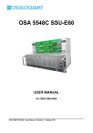
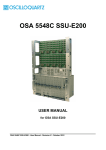
The TimeSource 3500, shown in Figure 1-1, is a Primary Reference Source (PRS)
that receives and processes signals from GPS satellites, and outputs Stratum 1
synchronization signals traceable to UTC. TimeSource 3500 applications include
synchronization for central offices, wireless base stations, transmission nodes, and
other cases where a primary reference source can improve the performance of a
telecommunications network infrastructure.
Figure 1-1.
TimeSource 3500
The TimeSource 3500 is also ideal for installation in environments where receiving
GPS signals is difficult. Examples of environments hostile to GPS signals include
urban canyons which have a very limited view of the sky because of blockage from
nearby buildings, and high interference zones where GPS signals are jammed by
competing over-the-air signals.
The TimeSource 3500 creates timing outputs by ensembling signals from several
sources. The sources include GPS signals, an onboard rubidium local oscillator,
and optional T1 signals. Timing outputs created from the ensemble are composed
of the most stable and least noisy parts of each input. The performance of the T1
sources can be monitored and classified using standard measures. Synchronization
outputs are delivered in a framed, all-ones, T1 format, a 10 MHz signal, a 1 pps
signal, a composite clock format (optional), and a choice of time of day (TOD)
formats.
The TimeSource 3500 minimizes timing impairments, such as jitter and wander, that
are created by network and transmission systems. The synchronization timing is
traceable to the GPS, which provides the highest level of synchronization for
telephony networks. The TimeSource 3500 with its GPS input is a stand-alone office
PRS. With the optional inputs ensembled, holdover is extended if GPS signals are
disrupted.
20
TimeSource 3500 User’s Guide
097-72050-01 Revision M – October, 2007
Chapter 1 Description
Global Positioning System
Global Positioning System
The United States Government developed the GPS navigation system. It is a
satellite-based, radio navigation aid designed to provide global, all-weather, precise
navigation and timing capability to users 24 hours a day.
The satellites, circling the earth at approximately 12,550 statute miles, are arranged
in 6 orbits with 4 operational satellites in each orbit. Each satellite has an orbital
period of approximately 12 hours. This configuration assures that a minimum of
4 satellites, and as many as 12, are in view anywhere in the world at all times.
The TimeSource 3500 tracks all satellites within its field of view. The performance of
each tracked satellite is observed and compared to the others, and available for use
in the timing solution. A satellite with unacceptable performance data is dropped
from the timing solution.
GPS antennas must have line-of-sight access to the transmitting satellites. Any
structure that interferes with, or blocks, the view of the satellites disrupts the
reception of the signals, and can adversely impact the timing performance of a
receiver.
The TimeSource 3500 bridges frequent GPS outage periods with BesTime
algorithms, its ultra-stable Rubidium local oscillator and advanced holdover
technology. The technology anticipates the outages and uses BesTime-generated
predictor values to optimize the performance of timing without direct satellite input.
Physical Description
The TimeSource 3500 consists of a shelf, a plug-in card, an antenna, cables,
hardware, and software. Optional system configurations include eight additional T1
outputs, eight additional composite clock outputs, two IRIG-B TOD timing outputs,
or eight mixed E1/T1 outputs.
The shelf (Figure 1-2) occupies two rack mounting units (RU), and can be mounted
in a 19 inch rack or a 23 inch rack. One RU (1.75 in.) of air space above the
TimeSource 3500 is required for proper ventilation. Other than a communications
connector on the front panel, all connectors are at the rear of the shelf.
Four types of antennas are available:
roof antenna for installation outdoors, usually on a roof
mechanical antenna for installation indoors, mounted on a window sill or wall for
reception through a window
self-adhesive antenna for installation indoors, adhered directly to a window
wall antenna for installation outdoors, through a hole in the wall
097-72050-01 Revision M – October, 2007
TimeSource 3500 User’s Guide
21
Chapter 1 Description
Physical Description
Air space (required for proper ventilation)
3.25 in.
17.25 in.
Figure 1-2.
Shelf
Roof Antenna
The roof antenna (Figure 1-3) is encased in weather-resistant plastic housing for
outdoor installation, usually on a roof. A single coaxial cable carries signals and
power between the antenna and the shelf.
5.9 in.
18.86 in.
1.83 in.
Figure 1-3.
Roof Antenna
Mechanical Window Antenna
The mechanical window antenna (Figure 1-4) may be attached to a window sill or
wall, in any position that allows the antenna to be moved flush against the window.
The antenna can be swung away from the window for window maintenance, and
returned to its original position.
A single length of coaxial cable carries signals and power between the antenna
assembly and the shelf.
22
TimeSource 3500 User’s Guide
097-72050-01 Revision M – October, 2007
Chapter 1 Description
Physical Description
Antenna
Coaxial Cable
Mounting Assembly
IF Converter
17 in.
Coaxial Cable
to TimeSource 3500 Shelf
(not included with
antenna assembly)
Figure 1-4.
Mechanical Window Antenna
Self-Adhesive Window Antenna
The self-adhesive window antenna assembly (Figure 1-5) consists of the antenna
and two pieces of self-stick hook-and-loop fabric fasteners (Velcro brand or
equivalent). The hook-and-loop fabric attaches directly to a window. Coaxial cables
carry signals and power between the antenna and the IF converter, and between
the IF converter and the shelf.
GPS WINDOW
ANTENNA
Figure 1-5.
Self-Adhesive Window Antenna
097-72050-01 Revision M – October, 2007
TimeSource 3500 User’s Guide
23
Chapter 1 Description
Functional Description
Wall Antenna
The wall antenna (Figure 1-6) is mounted on the outside of a building wall. The
antenna attaches magnetically to the mounting bracket. The cable from the antenna
is routed through a hole drilled in the wall. Coaxial cables carry signals and power
between the antenna and the IF converter, and between the IF converter and the
shelf.
Antenna Mounting Bracket
Antenna
Coaxial Cable
3 in.
Figure 1-6.
Wall Antenna
Functional Description
Overview
Figure 1-7 shows the main functions of the TimeSource 3500. The center of the
TimeSource 3500 is the BesTime Ensemble Timing Generator, which uses the
BesTime algorithm to analyze the phase and frequency relationships, individually
and collectively, of the timing sources. Each type of timing source has a particular
characteristic that gives it an advantage over other sources, as listed in Table 1-1.
The BesTime algorithm uses the best characteristic of each source to produce an
output signal with greater overall accuracy and stability than any single source. The
contribution of a source is based on its deviation from the weighted average of all
the sources. The more accurate a source, the more weight it has in the final output.
Every source is under constant evaluation and its contribution subject to periodic
adjustment. The output is essentially the best performance of the best source.
24
TimeSource 3500 User’s Guide
097-72050-01 Revision M – October, 2007
Chapter 1 Description
Functional Description
Clock input & dc
power to antenna
Alarm
Interface
Alarms
Microprocessor
COM Ports
Ethernet Port
Status Lamps
IF
Interface
Antenna
input
Optional sources
T1 Output A
Local
Oscillator
T1 Span
Input #1
Clock
Extractor
T1 Span
Input #2
Clock
Extractor
–48 V A
–48 V B
Power
Supply
BesTime
Ensemble
Timing
Generator
T1 Output B
1 pps Output
TOD Output
10 MHz Output
Power to
shelf
8 Composite
Clock Outputs
8 mixed E1/T1
Outputs
2 IRIG-B
Outputs
8 T1 Outputs
8 mixed T1/CCK
Outputs
Optional outputs
Figure 1-7.
Block Diagram
Table 1-1. Timing Source Characteristics
Source
Characteristic
Local Oscillator
Short term stability
T1 Line
Intermediate term stability
GPS Signal
Long term stability
097-72050-01 Revision M – October, 2007
TimeSource 3500 User’s Guide
25
Chapter 1 Description
Functional Description
Antenna
The antenna types include a roof antenna, mechanical window antenna,
self-adhesive window antenna, or wall antenna. All antennas include a GPS
receiver, amplifier, and intermediate-frequency (IF) downconverter.
The GPS Receiver extracts a clock signal from the GPS satellite signals. The
receiver can process the signals from all satellites in view, while simultaneously
using the Earth location of the receiver and other factors to determine an accurate
clock signal.
An internal amplifier provides signal gain.
The downconverter converts the L1-band GPS signal to IF for long-distance
transport on the coaxial antenna cable. The antenna cable provides current from the
shelf to the antenna, and transports GPS satellite IF signals from the antenna to the
shelf.
Antenna Installation and Lightning Protection
The TimeSource 3500 standard wall antenna kits do not include lightning
protectors. When the antenna is installed on the side of the building, the antenna is
in the zone of protection and is protected from lightning strikes as described in the
Standard for the Installation of Lightning Protection Systems (NFPA 780), 2000
edition.
The zone of protection shall include the space not intruded by a rolling sphere
having a radius of 150 ft (45.72 meters). Where the sphere is tangent to earth and
resting against a strike termination device, all space in the vertical plane between
the two points of contact and under the sphere shall be considered to be in the zone
of protection. A zone of protection shall also be formed where such a sphere is
resting on two or more strike termination devices and shall include the space
between those devices (see Figure 1-8). All possible placements of the sphere shall
be considered when determining the zone of protection using the rolling sphere
model.
26
TimeSource 3500 User’s Guide
097-72050-01 Revision M – October, 2007
Chapter 1 Description
Functional Description
150 ft.
(45.72 m) R
Figure 1-8.
Zone of Protection
For structure heights exceeding 150 ft (45.72 m) above earth or above a lower strike
termination device, the zone of protection shall be considered to be the space in the
vertical plane between the points of contact and under the sphere where the sphere
is resting against a vertical surface of the structure and the lower strike termination
device or earth. The zone of protection shall be limited to the space above the
horizontal plane of the lowest terminal unless it can be extended by further analysis,
such as in rolling the sphere to be tangent to earth.
If the wall antenna is installed outside the zone of protection, Symmetricom offers
an outdoor and/or indoor lightning protector kits for these installations. Refer to
Chapter 2, Engineering & Ordering, for more information on these kits.
IF Interface
An IF interface accepts the signals from the antenna/IF converter, and provides the
clock information to the BesTime Ensemble Timing Generator.
GPS Receiver
The GPS Receiver continuously tracks up to eight satellites, using both carrier and
code lock. The recovered pseudo-range measurement data is processed to
determine precise time and frequency state estimates for the local oscillator. The
receiver software is optimized to track and update state estimates, when as few as
one satellite is in view.
Local Oscillator
A rubidium oscillator, based on a digitally controlled servo-loop, provides an
ultra-stable local oscillator signal, which is sent to the BesTime Ensemble Timing
Generator.
097-72050-01 Revision M – October, 2007
TimeSource 3500 User’s Guide
27
Chapter 1 Description
Functional Description
Clock Extractors
A clock extractor circuit extracts a timing signal from each external reference
source. (External sources, other than the GPS antenna, are optional.) The extracted
timing signal is sent to the BesTime Ensemble Timing Generator.
Power Supply
A power converter filters and converts –48 volts dc power supplied to the shelf into
the voltages required by the circuitry.
NTP TimeServer
The TimeServer is a Simple Network Time Protocol (SNTP) device. The SNTP
TimeServer function is provided via the TimeSource Ethernet interface and
associated IP address. User software requests UTC time of day via NTP protocol.
The TimeSource SNTP server responds with current UTC time. The TimeServer is
compatible with the SNTP RFC-1769 format.
To enable the SNTP feature, a password must be entered using the ED-EQPT TL1
command. If a user makes a fourth attempt of an incorrect password entry, the
TimeServer will lock out the user for 1 hour.
Network Time Protocol Password Activation
Use of the Network Time Protocol (NTP) feature requires activation with a
password. Activation is accomplished through receipt of a Network Time Protocol
Activation Certificate from Symmetricom. This certificate contains the unit purchase
order number, unit model number, unit activation date, unit serial number, and unit
activation key. The unit activation key is the password that enables the NTP feature.
To activate the NTP feature, enter the TL1 command printed on the activation
certificate. Once activated, this feature will be permanently enabled. To order the
NTP feature, contact the local Symmetricom sales representative.
BesTime Ensemble Timing Generator
Clock signals from the GPS antenna (via the IF interface), local oscillator, and
optional T1 span lines are used as sources by the BesTime algorithms in the
BesTime Ensemble Timing Generator. The signals are analyzed for MDEV, TDEV,
and other phase and frequency characteristics.
The BesTime Ensemble Timing Generator uses mathematical models to analyze
each clock. The ensemble algorithms use the comparisons and analyses to
generate a highly stable timing signal, which uses the best qualities of all inputs.
28
TimeSource 3500 User’s Guide
097-72050-01 Revision M – October, 2007
Chapter 1 Description
Functional Description
Eight Mixed T1/E1/2.048 MHz Outputs (990-72050-06 Systems
Only)
This feature enables a user to mix any combination of E1 and T1 outputs. A user
can also use any combination of framing. For E1, CCS, CAS, CCS with CRC4, and
CAS with CRC4 can be used per G.703 table 6. For T1, D4 or ESF can be used per
ANSI T1.101. In addition, there is support for analog (2.048 MHz) per G.703 table
10 and support for synchronization status messaging (SSM) per TR-33 for E1 and
T1.
Eight Mixed T1/CCK Outputs (990-72050-07 Systems Only)
This feature enables a user to mix any combination of T1 and CCK outputs. For T1,
D4 or ESF framing can be used per ANSI T1.101. Support for SSM is per TR-33 for
T1.
T1 Outputs
The BesTime Ensemble Timing Generator provides the timing for the T1 timing
signal available at the T1 OUT A and B connectors in a framed, all-ones format,
which can be set to ESF or D4 framing.
Additional T1 Outputs (990-72050-02 Systems Only)
This option provides eight additional T1 outputs. The outputs are available at the
OPTIONS I/O wire-wrap pins on the rear panel. These outputs function the same as
the standard T1 outputs.
TOD Output
The BesTime Ensemble Timing Generator provides the timing for the TOD timing
signal available at the RJ-45 connector, which provides time code to devices
compatible with NTP Type 4 or Cisco ASCII format.
IRIG-B TOD Outputs (990-72050-05 Systems Only)
This option provides two additional TOD outputs in IRIG-B format. The outputs are
available at a BNC output module on the OPTIONS I/O wire-wrap pins mounted on
the rear panel.
The BesTime Ensemble Timing Generator provides the timing for the TOD timing
signal, which provides timing code to devices compatible with IRIG-B.
097-72050-01 Revision M – October, 2007
TimeSource 3500 User’s Guide
29
Chapter 1 Description
Functional Description
1 PPS Output
The BesTime Ensemble Timing Generator provides the timing for the
1 pulse-per-second timing signal available at the 1 PPS connector, which can be
used for application-specific requirements. This signal is not squelched during an
alarm.
10 MHz Output
The BesTime Ensemble Timing Generator provides timing for the 10 MHz timing
signal available at the 10 MHZ connector, which can be used for local cellular
frequency or testing purposes. This signal is not squelched during an alarm.
Composite Clock Outputs
(990-72050-03 Systems Only)
This option provides eight composite clock signals. The outputs are available at the
OPTIONS I/O wire-wrap pins on the rear panel.
Alarm Interface
The microprocessor delivers alarms to normally open dry-contact type connections.
Alarms are also indicated by the front-panel status lamps.
Communication Ports
Three serial communication ports carry TL1 commands, responses, and
autonomous messages between the TimeSource 3500 and an external terminal.
Ethernet
TimeSource 3500 has six Ethernet ports to carry TL1 commands, responses, and
autonomous messages between the TimeSource 3500 and an external terminal, or
an Element Manager, or both. The user can configure the IP address, subnet mask,
and gateway address for the Ethernet ports.
Four ports (5001, 5002, 5003, and 5004) are configured to act as though a
serial-port communication terminal were connected to them. These ports
communicate TL1 commands, responses and autonomous messages.
Two additional ports communicate with Element Managers, which may have NMS,
OSMF, or similar software. An Element Manager establishes a connection with one
port (5551) for TL1 commands and responses. Another port (5550) establishes a
connection to an Element Manger, sends autonomous messages, and closes the
connection when finished.
30
TimeSource 3500 User’s Guide
097-72050-01 Revision M – October, 2007
Chapter 1 Description
Functional Description
Passthrough
The Passthrough feature of the TimeSource 3500 allows the unit to front a DCD
product to provide one management interface for a user site. Passthrough allows a
user to do the following:
COM1 or COM2 is connected to the DCD product
The user port can be any unused port, including the Ethernet port
Messages can pass from a user to the DCD product and from the DCD product
to a user through the TimeSource 3500
The TID (SID for DCD) is used to identify commands that go to the DCD product.
The TimeSource 3500 passes any TID not its own through to the DCD product. In
the reverse direction, all commands received from the DCD product are passed
through to the user.
Note: The TID of the TL1 command must be the SID of MIS.
DCD is fully managed except for firmware download.
GUI interfaces to the DCD product are not supported through the Passthrough,
only TL1 responses are available.
Figure 1-9 shows a TimeSource 3500 Passthrough setup.
DCD PASSTHRU
DCD-5X
User port (any port)
Straight cable
TS-3500
DCD USER PORT
COM 1, 2, 3
IP: 5001 - 5004
COM 1, 2, or 3
Figure 1-9.
COM 1 or 2 (COM 1 is
DB-25 and COM 2 is RJ-45)
TimeSource 3500 Passthrough Function
Alarm Programmability
Releases of TimeSource (1.05.03 and above) allow the user to provision the alarm
escalation parameters that were hardcoded in the previous releases of TS3000.hex.
The defaults for this release remain the same as were previously hardcoded. This
feature can be used to set the programmability for such alarms as GPS,
HOLDOVER, and SPAN-X.
097-72050-01 Revision M – October, 2007
TimeSource 3500 User’s Guide
31
Chapter 1 Description
Functional Description
The TS3500 alarms can be programmed for GPS and HOLDOVER types of events.
The SPAN-X alarms can be programmed for AIS, ERROR, and LOS types of
events.
The user can set the parameters for SEVERITY1 and SERAFF1 which initially
come into effect when the condition is detected. The user can also set the
parameters for SEVERITY2 and SERAFF2 which come into effect after TIME
(another user programmable parameter).
The system also allows the user to set a parameter to define how outputs should
behave in an alarm condition (see ALMOUT and ALMCOND settings). Outputs can
be set to AIS, Squelch, or SSM when Holdover alarm severity is set to minor or
major. AIS, Squelch, or SSM is not evoked if Holdover severity is set to event
(factory default for initial severity). Outputs can also be set to ignore alarm
conditions.
Startup
When the TimeSource starts up, the CRIT lamp lights. The CRIT lamp remains on
for approximately 60 seconds and then shuts off.
During startup, the TimeSource performs several self-tests to verify the integrity of
the hardware and software. Neither communication nor outputs are possible at this
time, and the CRIT lamp is switched on. Once the self-tests are done, a connection
to the system can be made and the events viewed.
Two events are initially provided. These events are:
"Power Up Restart"
"Settling Period"
In the "Power Up Restart" event, which lasts for approximately 2 minutes, the
system does additional checks and starts all the various tasks within the system.
The "Settling Period" event is an informational message that lasts until the
TimeSource’s BesTime engine reaches the highest possible stable point. The time
taken to reach this point depends on satellite availability, type of oscillator, ambient
temperature, etc. and may take up to 20 hours to clear. Since "Settling Period" is
independent of the quality of the output and is the normal behavior of the system, it
is generated as an event rather than an alarm. If "Settling Period" is not cleared
after 24 hours, another "Settling Period" event is generated as a marker. This is still
Non-Service-Affecting.
As soon as the "Power Up Restart" message is cleared, the "BT3 Warmup" event is
generated. This is also an informational message that lasts till the time it takes the
system to acquire the satellites, warm up the oscillator, and start giving out valid
outputs. It may take up to 2 hours for the message to clear, but typically takes
approximately 40 minutes. During the "BT3 Warmup" time, the outputs will generally
32
TimeSource 3500 User’s Guide
097-72050-01 Revision M – October, 2007
Chapter 1 Description
Functional Description
be squelched. If the outputs are enabled using the TL1 command
(ED-EQPT::TS3500:ctag:::ALMCOND=ALW;) they may not be within the PRS
mask. In case the system is not able to acquire sufficient number of satellites and/or
discipline the oscillator within 2 hours, the event escalates into a Non Service
Affecting Minor alarm.
Once the warm up is complete, the system generates valid outputs and the event is
cleared.
Bridging/Holdover Behavior
In the TimeSource 3500, alarms are designed with a built-in hysteresis. This means
that an alarm is not announced as soon as some error condition is detected. There
is a pre-integration time during which the error must persist in order for the alarm to
be announced. On the flip side, the error must be clear for a certain time for an
alarm condition to be cleared. This ensures that intermittent conditions are not
flagged unnecessarily.
During the normal working of the TimeSource 3500, it is a very common occurrence
that the GPS satellites may not be visible during certain parts of the day, depending
on the installation of the antenna. This is particularly true with wall and, especially,
window antenna installations. The TimeSource 3500 has been designed to work
around this situation.
The TimeSource 3500 enters "Bridging" mode when all satellite locks are lost.
There is no TL1 annunciation that the system has entered "Bridging" mode. This is
"Non Service Affecting" and the outputs are not affected. The system runs off its
internal oscillator and the outputs are kept within the GR-2830 PRC mask by the
BesTime engine.
When "Bridging" mode persists for more than 30 minutes, the system enters
"Holdover" mode and a "Holdover" event is generated. This may or may not affect
the outputs depending on the alarm integration parameters that can be set by the
user.
The system allows the user to set various parameters for GPS error, Holdover error,
and SPAN error conditions. These parameters are:
Initial Severity
Initial Service Affecting state
Integration Time
Final Severity
Final Service Affecting state
097-72050-01 Revision M – October, 2007
TimeSource 3500 User’s Guide
33
Chapter 1 Description
Functional Description
The system also allows the user to set a parameter to define how outputs should
behave in an alarm condition (see ALMOUT and ALMCOND settings). Outputs can
be set to AIS, Squelch, or SSM when Holdover alarm severity is set to minor or
major. AIS, Squelch, or SSM is not evoked if Holdover severity is set to event
(factory default for initial severity). Outputs can also be set to ignore alarm
conditions.
When the "Holdover" event is announced, it is announced with the Initial Severity
and Initial Service Affecting state. If the "Holdover" event persists for the length of
the Integration Time, the alarm is escalated to the Final Severity and Final Service
Affecting state.
The "Holdover" event/alarm is cleared when the satellites are visible again.
Time Figure of Merit
Time Figure of Merit (TFOM) is a moving 24 hour measurement reported in
nanosecond (ns) against an ideal model. TFOM has a frequency component used
to measure GPS wander caused by multipath and a time loop component used to
measure long term oscillator wander.
The TFOM alarm threshold is set to 500 ns and is not user configurable. A TFOM
below 500 ns indicates a stable clock well within PRS output performance
specifications. A TFOM between 500 ns and 800 ns is an early warning of a clock
becoming unstable and in danger of going out of PRS specification. When the
TFOM exceeds 800 ns, the clock is no longer meeting the stratum 1 MTIE mask.
TFOM is most useful for installations where the antenna has a limited view to the
sky. This is defined as any installation where fewer than 4 satellites are in view for
greater than 1 hour per day on average. This is typical for installations where the
antenna is mounted in a window or on an outside wall of a building, but can also
include rooftop installations with partial sky view blockage. TFOM’s primary use is to
help troubleshoot multipath issues associated with antenna placement and incorrect
latitude, longitude, and/or altitude (location) data entry.
Installations with full view to the sky see 4 satellites 23+ hours a day, seven days a
week. It is relatively easy to filter out multipath signals using multiple satellites and
simple voting schemes. In addition, rooftop antennas are mounted vertically and all
signals below the horizon are obvious multipath interference and can be masked
out of the system. With 4 satellites in view, the GPS timing receiver will provide an
error-free lock on its location through an automatic survey function.
With wall/window installations, voting schemes become less effective as the
number of satellites in view drop. Also, wall/window antennas are mounted
horizontally and are prone to seeing multipath signals reflected off nearby structures
and the ground. Wall/window installations also require the manual input of location
data, creating the potential for errors and the need to detect these errors.
34
TimeSource 3500 User’s Guide
097-72050-01 Revision M – October, 2007
Chapter 1 Description
Functional Description
The TimeSource has unique algorithms to account for, and defeat, the added
multipath complications and location data entry error possibilities of wall/window
antenna installations. Large amounts of multipath or major errors in location data
entry are easier to identify and are detected over a relatively short period of time.
These short-term errors are normally reported via the TimeSource tracking success
rate parameter.
Small amounts of multipath or minor errors in location data entry are difficult to
identify because they mimic a true signal or an expected satellite behavior pattern.
Single satellite reception over limited periods of time complicates the ability for the
internal TimeSource algorithms to filter out these ghost signals and longer periods
of time are needed to sort them out. TFOM tracks and reports these long-term
errors.
At time of installation, marginal or unacceptable TFOM readings can indicate the
need to adjust the antenna placement, the mask angle, and/or the location data.
Relatively small changes in the antenna placement can improve the ability of the
system to see satellites and therefore improve performance. The mask angle can
be adjusted to block out lower elevation portions of the sky if there is good visibility
at higher elevations, thereby reducing multipath. Correct location data is very
helpful in identifying and tracking satellites.
In addition, a clock may be stable for many weeks, months, or years but could
degrade because of changes in its environment. TFOM is useful in detecting these
infrequent subtle changes including:
Maturing foliage or seasonal foliage changes
Installation of new transmitters nearby (i.e. wireless base station)
New building construction
Variations in the day-to-day temperature of the CO
Success Rate
Success rate is a moving 24 hour window indicating the TimeSource's ability to lock
to and use the GPS as part of the system's timing solution. This metric is reported
as a percentage (%) ratio of the total good minutes that the system uses GPS in a
day (maximum 1440 minutes/day). Success rate can range in value from 0% to
100%.
Success rate is determined by totaling all good minutes of satellite(s) visibility that
the system is using and dividing by the total maximum possible minutes in a day;
when satellites are not being used in the solution usually because of low satellite
visibility or multipath effects, the minutes are not counted in the good minutes
category.
097-72050-01 Revision M – October, 2007
TimeSource 3500 User’s Guide
35
Chapter 1 Description
Functional Description
The success rate of a rooftop antenna configuration will generally be higher than a
wall/window antenna configuration due to the fact that rooftop installations will have
a better view of the sky than wall/window installations which typically may see only
portions of the sky with fewer satellites.
TFOM (Merit) was discussed in detail in the preceding section, and this metric plays
a key role in the calculation of Success Rate. When TFOM is greater than 500 ns,
this is a warning that the system clock is becoming unstable and maybe going out of
PRS specification. Success Rate uses this as a threshold, so when the TFOM value
is equal to or below 500 ns, minutes will be calculated within the good minutes
category. Conversely, when the TFOM value is above 500 ns, these minutes will not
be considered as good minutes.
36
TimeSource 3500 User’s Guide
097-72050-01 Revision M – October, 2007
Chapter 2 Engineering and Ordering
This chapter provides information to assist in planning the installation and ordering
a system appropriate for a specific site.
In This Chapter
Antenna Guidelines
Shelf Considerations
Systems
Antennas
User-Supplied Tools and Materials
097-72050-01 Revision M – October, 2007
TimeSource 3500 User’s Guide
37
Chapter 2 Engineering and Ordering
Antenna Guidelines
Antenna Guidelines
Perform a site survey as described in the following procedure before ordering the
system. Use the guidelines and considerations in the Roof/Window/Wall Antenna
Location and Cabling Guidelines sections that follow this procedure and in Shelf
Considerations, on page 45.
Site Survey
1. Determine the shelf location.
2. Determine the best location for mounting the antenna (less than 1,000 ft of cable
from the shelf). Use the guidelines and considerations in the Roof Antenna
Location and Cabling Guidelines in the next section.
3. If a roof-mounted antenna is installed, determine the location of the grounding
point for the lightning suppressor, then determine the location of the lightning
suppressor. The cable length between the lightning suppressor and the
grounding point must be less than 15 ft. If the grounding point is inside the
building, the cable length between the grounding point and the cable entry must
be less than 50 ft. Valid lightning suppressor grounding points are:
Valid ring ground system (usually for roof-mounted lightning suppressors)
Structural steel of building (for interior-mounted or exterior-mounted lightning
suppressors, attach with a cad weld)
Central Office ground plate (usually for interior-mounted lightning suppressors)
4. If a roof-mounted antenna is installed, two lengths of cable are required. Plan the
cable route and measure the length of cable required between the antenna and
the lightning suppressor, and between the lightning suppressor and the shelf.
5. If a window or wall-mounted antenna is installed, plan the cable route and
measure the length of cable required between the antenna and the shelf.
6. Determine the two separate –48 V power sources for the shelf. If only one –48 V
power source is available, it must be cabled to both TimeSource 3500 power
inputs.
Roof Antenna Location and Cabling Guidelines
Electrical Shock Caution: To avoid electrical shock and possible
personal injury, do not select an antenna location near high-voltage
sources. Install the antenna in an easily maintainable location.
38
TimeSource 3500 User’s Guide
097-72050-01 Revision M – October, 2007
Chapter 2 Engineering and Ordering
Antenna Guidelines
The ideal roof antenna location provides a clear, unobstructed view of the sky from
the zenith to the horizon line, and 360 degrees around the horizon.
A compromise often must be made between location and satellite field of view. With
a smaller field of view, the TimeSource 3500 can use fewer satellites in the solution
for GPS derived time. The TimeSource 3500 will operate with an average of one
satellite in view for 40 percent of the time in a day.
Signals closer to the horizon are often subject to multipath effects, which degrade
the timing solution. The TimeSource 3500 can be set to ignore, or mask, all signals
from the horizon up to a chosen angle of elevation (mask angle). (See Figure 2-1).
Antenna position
Antenna
field of view
Obstructions
toward the pole
if possible
10°
Mask angle*
10°
Mask angle*
Horizon
Equator
Pole
* An angle of 10° masks objects up to about 3.5 ft above
the horizon at 20 ft from the antenna (illustration at right.)
Figure 2-1.
10°
3.5 ft
20 ft
Antenna Field of View
Due to the geometry of the GPS satellite orbits, more satellites are visible in the
direction of the equator than the poles. If possible, place the antenna so that the
antenna has a clear view toward the equator (toward the south in the northern
hemisphere, or toward the north in the southern hemisphere). Up to 60 degrees of
arc, centered at the pole, may be blocked with little effect in the temperate latitudes.
This note is less applicable in latitudes nearer the equator.
The total of obstructions above the mask angle should not obscure more than 25
percent of the total field of view (90 degrees of azimuth) (Figure 2-2).
097-72050-01 Revision M – October, 2007
TimeSource 3500 User’s Guide
39
Chapter 2 Engineering and Ordering
Antenna Guidelines
Figure 2-2.
Antenna Location Examples
Notes:
1. Place the antenna high enough on the tower that obstructions are
below the mask angle; mount the antenna more than 3 feet away
from the tower, and far below the interference of the antennas at
the top of the tower. Tower mounting is the least desirable
location because of the potential for severe multipath, and
difficulty in troubleshooting and maintenance.
2. Place the antenna high enough that the roof structure and tree
are below the mask angle, and the water tower does not block
more than 12.5 percent of the sky.
No single obstruction should block a large portion (45 degrees of azimuth) of the
view.
The most important obstructions are within 1/4 mile (400 yards) of the antenna.
Obstructions may include, but are not limited to, towers, buildings, other
construction, trees, and high-voltage power lines.
Attempt to avoid locating the antenna within 30 degrees azimuth of the transmission
direction of any transmitting antenna in the area, even if the transmitting antenna
operates at a different frequency. A transmitting antenna may cause the GPS
antenna to become overloaded and reduce its reception capabilities.
The minimum horizontal distance from other receiving antennas is 3 feet.
To reduce multipath signal distortions, the minimum horizontal distance from
vertical reflective structures (e.g., heating ducts, equipment housings, etc.) is twice
the height of the structure, and no less than 10 feet (Figure 2-3).
40
TimeSource 3500 User’s Guide
097-72050-01 Revision M – October, 2007
Chapter 2 Engineering and Ordering
Antenna Guidelines
Do not locate the antenna underneath high power lines. If this cannot be avoided,
ensure the antenna is placed at least twice as far from the power line as the power
line is high (to avoid danger to personnel and multipath effects).
Cables must be run as straight as possible. All cables should be routed in
accordance with local company practices.
Note: Keep all impedances as low as possible, otherwise the
grounding scheme may be defeated.
Observe the following guidelines during the placement and installation of the
cables:
Route cables as straight as possible (bends in the cable increase impedance at
lightning frequencies), in accordance with local company practices.
Any opening where conduit enters the building must be waterproofed per local
company practices.
Treat all exposed connections with an electrically conductive anti-corrosion
compound (Kopr-Shield or equivalent).
Caution: Avoid small-radius turns and unnecessary turns.
Figure 2-3.
Sample Rooftop Antenna Mount
097-72050-01 Revision M – October, 2007
TimeSource 3500 User’s Guide
41
Chapter 2 Engineering and Ordering
Antenna Guidelines
Note: Figure 2-3 is an example only. Not all parts are available from
Symmetricom.
Roof Antenna Earth Ground Location Guidelines
The roof ring ground system, a Central Office grounding plate, and building
structural steel are examples of valid earth ground points. If the mounting plate
cannot be bolted to a valid earth ground, or if the mounting plate is to be installed in
a nonmetallic junction box, bolt the mounting plate to a point within 15 feet of the
valid earth ground.
Roof Antenna Cable Choices
The antenna assembly uses the same coaxial cable for power and antenna signals.
The length of cable is determined by circumstances of the installation and site.
Symmetricom offers RG-59/U plenum-rated coaxial cable (20 AWG [0.812 mm], 75
ohm coaxial) with male TNC connectors attached, in the following lengths:
10 feet (060-72010-01)
20 feet (060-72010-02)
50 feet (060-72010-05)
100 feet (060-72010-10)
200 feet (060-72010-20)
300 feet (060-72010-30)
500 feet (060-72010-50)
600 feet (060-72010-60)
800 feet (060-72010-80)
1000 feet (060-72010-99)
Two cables are required: one to connect the antenna to the lightning suppressor,
and another to connect the lightning suppressor to the TimeSource 3500 Shelf.
Optionally, one length of coaxial cable may be ordered, which must be cut and
prepared with end-connectors at the point where the suppressor is located.
42
TimeSource 3500 User’s Guide
097-72050-01 Revision M – October, 2007
Chapter 2 Engineering and Ordering
Antenna Guidelines
The following items, which must be ordered separately, are available for this type of
installation:
TNC connector kit (093-72010-98) includes:
– TNC connectors for RG-59/U cables (8)
– Rubber boots (8)
– TNC adapter connectors (2)
TNC crimp tool (154-00023-01)
Window and Wall Antenna Location Guidelines
When selecting a window or wall in which to install the antenna, select the window
or wall which has the maximum unobstructed view of the sky. Do not select a
window or wall which has the view of the sky obstructed by trees, buildings, or
towers. The smaller the field of view, the fewer the number of satellites that can be
used in the timing solution for GPS derived time. The consequence of this is that the
timing generator may experience holdover more often and may eventually go into
alarm.
Due to the geometry of the GPS satellite orbits, more satellites are visible in the
direction of the equator than the poles. If possible, select a window or wall which
has a clear view toward the equator (toward the south in the northern hemisphere,
or toward the north in the southern hemisphere). This guideline is less applicable in
latitudes nearer the equator and more important nearer the poles.
Certain parts of the sky are blocked from view. These obstructions usually exist
from the horizon line and up, for example, a building or mountain. The processor
inside the GPS receiver processes every piece of the sky, whether it is blocked or
not. If unproductive parts of the sky are masked from the processor’s view, the
processing time is reduced, and the timing solution can be achieved more quickly.
Note: A band of the sky from the horizon up to a point where a view
of the sky begins is called a mask angle. The mask angle typically
should not exceed 10 degrees (if the mask angle is set too high, too
little of the sky is available to the receiver). Determine the mask angle
for the selected antenna location (Figure 2-4) and make a note of it.
The mask angle, in degrees, will be entered during the initial setup.
097-72050-01 Revision M – October, 2007
TimeSource 3500 User’s Guide
43
Chapter 2 Engineering and Ordering
Antenna Guidelines
TimeSource 3500
Antenna
20 ft
10° mask angle*
Note: TimeSource 3500
3.5 ft
does not detect satellites in
the masked area.
*An angle of 10° masks objects up to about 3.5 ft above the
horizon at 20 ft from the antenna.
Figure 2-4.
Antenna Mask Angle
Window and Wall Antenna Cable Choices
A window or wall antenna includes an attached coaxial cable terminating in a male
SMA connector.
A separate cable is required to connect the IF converter to the TimeSource 3500
shelf. Two types of plenum-rated cable are available.
The cables with longer length capabilities (060-72010-xx) are RG-59/U (20 AWG
[0.812 mm], 75 ohm coaxial) with male TNC connectors attached to each end.
Assembled cables are available in the following lengths:
10 feet (060-72010-01)
20 feet (060-72010-02)
50 feet (060-72010-05)
100 feet (060-72010-10)
200 feet (060-72010-20)
300 feet (060-72010-30)
500 feet (060-72010-50)
600 feet (060-72010-60)
800 feet (060-72010-80)
1000 feet (060-72010-99)
The more flexible cables (060-72050-xx) are Mini RG-59/U (20 AWG [0.812 mm],
75 ohm coaxial) with male TNC connectors attached to each end. Assembled
cables are available in the following lengths:
44
50 feet (060-72050-05)
100 feet (060-72050-10)
200 feet (060-72050-20)
500 ft (060-72050-50)
TimeSource 3500 User’s Guide
097-72050-01 Revision M – October, 2007
Chapter 2 Engineering and Ordering
Shelf Considerations
IRIG-B TOD (990-72050-05 System Only)
If using the IRIG-B TOD outputs (990-72050-05 TimeSource 3500 System),
right-angle BNC connectors are provided to prevent small radius turns in the IRIG-B
TOD cables. The right-angle BNC connectors may be attached to the IRIG-B BNC
adapter (also provided) BNC connectors, to direct the cables from the shelf as
desired.
For each IRIG-B TOD output, a user-supplied cable with BNC connectors on each
end is installed between the adapter and the network elements requiring IRIG-B
TOD timing.
RJ-422–to–RS-232 TOD Converter
If using time-of-day (TOD), and the device receiving the time code accepts an
RS-232 signal instead of an RS-422 signal (for example, a Cisco router), an
RJ-422–to–RJ-232 TOD Converter Kit is required (ordered separately, part number
093-72000-98).
The RJ-422–to–RJ-232 TOD Converter Kit consists of a mounting plate with a
female RJ-45 connector, a female DB-25 connector, a TOD converter, and two
screws.
Install the converter anywhere (for example, on unused space on a rack) within
1,000 cable feet of the TimeSource 3500 shelf, and within 50 cable feet of the
device receiving the time code.
The user must supply two cables. One cable is a Category 5 four-pair RS-422
cable, 1,000 feet maximum, with RJ-45 connectors on each end. Route this cable
between the TimeSource 3500 Shelf and the converter.
The other cable is an RS-232 data communications cable, 50 feet maximum, with a
25-pin male D-type connector and another connector determined by the device
receiving the time code. Route this cable between the converter and the device
receiving the time code.
Shelf Considerations
The TimeSource 3500 Shelf can be mounted in a 19 inch rack or a 23 inch rack.
The shelf is shipped with supplied mounting ears positioned for flush mounting on a
23 inch rack. Attach the mounting ears, as shown in Figure 2-5, for flush mounting
or 5 inch offset mounting. Attach the long side of the mounting ear to the shelf for a
23 inch rack, and attach the short side of the mounting ears to the shelf for a 19 inch
rack. Mount the shelf in the rack according to standard company practices. Leave
one RU (1.75 inches) of air space above the TimeSource 3500 Shelf for proper
ventilation. Mount the shelf in the rack according to standard company practices.
097-72050-01 Revision M – October, 2007
TimeSource 3500 User’s Guide
45
Chapter 2 Engineering and Ordering
Systems
Note: Two screws can be used in each mounting ear if the holes in
the rack are spaced 1.75 inches apart.
Rear of rack
Rear of rack
Top of shelf
Top of shelf
A. Flush mounting – 19 in. rack
B. Flush mounting – 23 in. rack
Rear of rack
Rear of rack
Top of shelf
Top of shelf
C. 5 in. offset – 19 in. rack
D. 5 in. offset – 23 in. rack
Figure 2-5.
Rack Mounting Options
Systems
The TimeSource 3500 Systems available are listed below. The antenna must be
ordered separately.
Standard System (Two T1 Outputs)
This system (990-72050-01) includes:
46
TimeSource 3000 Shelf (090-72000-01)
TimeSource 3500 card (090-72050-01)
Hardware kit (093-72050-87)
System software CD (992-72050-xx) Version 1.05.04 or higher
TimeScan Craft (keyless version) software CD (992-46750-xx) Version 7.2.0 or
higher
TimeSource 3500 User’s Guide
097-72050-01 Revision M – October, 2007
Chapter 2 Engineering and Ordering
Systems
With Eight Additional T1 Outputs
This system (990-72050-02) includes:
TimeSource 3000 Shelf (090-72000-01)
TimeSource 3500 card with additional T1 outputs
(090-72050-02)
Hardware kit (093-72050-87)
System software CD (992-72050-xx) Version 1.05.04 or higher
TimeScan Craft (keyless version) software CD (992-46750-xx) Version 7.2.0 or
higher
With Eight Additional Mixed E1/T1 Outputs
This system (990-72050-06) includes:
TimeSource 3000 Shelf (090-72000-01)
TimeSource 3500 card with mixed E1/T1 outputs
(090-72050-06)
Hardware kit (093-72050-87)
System software CD (992-72050-xx) Version 1.05.04 or higher
TimeScan Craft (keyless version) software CD (992-46750-xx) Version 7.2.0 or
higher
With Eight Additional Mixed T1/CCK Outputs
This system (990-72050-07) includes:
TimeSource 3000 Shelf (090-72000-01)
TimeSource 3500 card with mixed T1/CCK outputs
(090-72050-07)
Hardware kit (093-72050-87)
System software CD (992-72050-xx)
Version 1.06.02 or higher
TimeScan Craft (keyless version) software CD (992-46750-xx) Version 7.2.0 or
higher
097-72050-01 Revision M – October, 2007
TimeSource 3500 User’s Guide
47
Chapter 2 Engineering and Ordering
Antennas
With Eight Composite Clock Outputs
This system (990-72050-03) includes:
TimeSource 3000 Shelf (090-72000-01)
TimeSource 3500 card with composite clock outputs
(090-72050-03)
Hardware kit (093-72050-87)
System software CD (992-72050-xx)
Version 1.05.04 or higher
TimeScan Craft (keyless version) software CD (992-46750-xx) Version 7.2.0 or
higher
With Two IRIG-B TOD Outputs
This system (990-72050-05) includes:
TimeSource 3000 Shelf (090-72000-01)
TimeSource 3500 card with IRIG-B TOD outputs
(090-72050-05)
IRIG-B BNC adapter board (090-72100-06)
Two right-angle BNC connectors (121-00530-01)
Hardware kit (093-72050-87)
System software CD (992-72050-xx)
Version 1.05.04 or higher
TimeScan Craft (keyless version) software CD (992-46750-xx) Version 7.2.0 or
higher
Antennas
The antennas available are listed below. A TimeSource 3500 System must be
ordered separately.
Roof Antenna
Antenna and mounting hardware kit (990-72050-96) includes:
IF antenna assembly (090-72010-71)
Mounting hardware kit (093-72010-71) (x1) which includes:
– Shim, 070-72010-75 (x2)
48
TimeSource 3500 User’s Guide
097-72050-01 Revision M – October, 2007
Chapter 2 Engineering and Ordering
Antennas
– Mast, 070-72010-76 (x1)
– Flange, 070-72010-77 (x1)
– Bolts, Pan Head Phillips Screw, 8 - 32 x ¾ inch, 125-83253-12 (x3)
– #8 Flat washers, 400111-0002 (x3)
– #8 Split Lock Washer, 125-00521-08 (x3)
– #8 Nut, 400160-0003 (x3)
Rooftop antenna installation kit (093-72050-96) includes:
– Mounting bracket for surge suppressor (070-00300-02)
– Surge suppressor (143-00018-01)
– Antenna cable bracket kit (093-00001-01)
– Miscellaneous installation parts
Mechanical Window Antenna
This antenna kit (990-72050-97) comes as a fully assembled antenna with the
following major components:
Antenna, with cable and SMA connector attached
(090-72050-90)
IF converter for window antenna gain (090-72050-72)
Mechanical chassis (074-72050-97)
Self-Adhesive Window Antenna
This antenna kit (990-72050-98) includes:
Antenna (090-71010-87)
IF converter for window antenna gain (090-72050-72)
Self-adhesive window antenna installation kit (093-72050-98) includes:
– RG316 cable, 10 feet (060-00062-01)
– Cable tie mounts (128-00302-02) and cable ties (128-00500-05)
Wall Antenna
Order one of these two available wall antenna kits based on the users antenna
cable length installation requirements:
This antenna kit (990-72050-99) includes:
IF converter for wall antenna gain (090-72050-71)
097-72050-01 Revision M – October, 2007
TimeSource 3500 User’s Guide
49
Chapter 2 Engineering and Ordering
User-Supplied Tools and Materials
Wall antenna kit (093-72050-99) includes:
– Antenna, with 19 feet of cable and SMA connector attached
(112-00013-01)
– Antenna mounting bracket (070-00383-02)
– Clamp tie mounts (128-00302-02) and cable ties (128-00500-05)
OR
This antenna kit (990-72050-95) includes:
IF converter for wall antenna gain (090-72050-71)
Wall antenna kit (093-72050-95) includes:
– Antenna, with 6 feet of cable and SMA connector attached (112-00013-03)
– Antenna mounting bracket (070-00383-02)
– Clamp tie mounts (128-00302-02) and
cable ties (128-00500-05)
Optional Wall Antenna Lightning Suppressors
There are two available wall antenna lightning suppressors, one for indoor mounting
and one for outdoor. Order one of these two optional lightning suppressors if
necessary.
Wall antenna indoor lightning suppressor kit (093-72050-94) (optional) includes:
– Mounting bracket (070-00300-02)
– Surge protector (143-00018-01)
– RG59 cable, 2 feet (060-72010-92)
Wall antenna L1 outdoor lightning suppressor kit (093-72050-93) (optional)
includes:
– Mounting bracket (070-00300-03)
– Surge protector (143-00018-02)
– RG316 cable, 10 feet, SMA(m)-SMA(m) (060-00062-01)
User-Supplied Tools and Materials
Ensure that the user-supplied tools and materials listed below are on hand for
installation, as applicable.
50
TimeSource 3500 User’s Guide
097-72050-01 Revision M – October, 2007
Chapter 2 Engineering and Ordering
User-Supplied Tools and Materials
For Roof Antenna Installation
1 inch diameter galvanized metal pipe, used as a mast to mount the antenna.
Mast should be long enough to position the antenna above any metal object on
the roof.
Screws to attach the lightning suppressor mounting plate.
Plumb line or bubble level.
Nonmetallic junction box for lightning suppressor (optional if lightning suppressor
mounted indoors).
1 inch diameter PVC pipe as conduit for outdoor cables.
PVC fittings appropriate to the installation and cable route.
Appropriate tools and materials for cutting and shaping PVC pipe.
PVC glue
6 AWG ground wire.
Spade lugs for 6 AWG ground wire.
Crimp tool for 6 AWG spade lugs.
Hardware to attach the ground wire to a valid earth ground.
Fire-stopping material to seal conduit hole in roof or wall.
Electrically conductive antioxidant compound (Kopr-Shield or equivalent) to coat
exposed connections to prevent oxidation.
Tool to cut cable, if installation requires custom lengths of cable.
Phillips Screwdriver
Wrench
1/4 inch hex Allen wrench
For Mechanical Window Antenna Installation
Drill with bit of appropriate size and type to make pilot holes for the mounting
screws
2 screws of appropriate size and type to attach the foot of the mechanical chassis
to a window sill or wall near a window.
Screwdriver
Cable ties or other method of securing cable
GPS handheld receiver, personal computer with GPS location software, or other
method of determining latitude, longitude, and altitude
For Self-Adhesive Window Antenna Installation
Drill with bit of appropriate size and type to make pilot holes for the mounting
screws
097-72050-01 Revision M – October, 2007
TimeSource 3500 User’s Guide
51
Chapter 2 Engineering and Ordering
User-Supplied Tools and Materials
4 screws of appropriate size and type to attach the IF converter to a wall or other
mounting surface.
Screwdriver
GPS handheld receiver, personal computer with GPS location software, or other
method of determining latitude, longitude, and altitude
For Wall Antenna Installation
Ladder, or safe method of reaching the antenna location on the exterior wall
Drill with bits of appropriate size and type to make pilot holes for the antenna
mounting bracket screws, and to make a hole through the wall for the antenna
cable
2 screws of appropriate size and type to attach the antenna mounting bracket to
an exterior wall.
Screwdriver
Electrically conductive antioxidant compound (Kopr-Shield or equivalent) to coat
exposed connections to prevent oxidation
Fire stopping material to seal the hole in the wall
GPS handheld receiver, personal computer with GPS location software, or other
method of determining latitude, longitude, and altitude
For Shelf Installation
A Phillips-head screwdriver for installing the TimeSource 3500 Shelf in a rack
Four screws to mount the shelf in a rack
Outputs, Power, and Miscellaneous
52
RG-58 coaxial cable for 1 PPS, 10 MHZ outputs
Ethernet 10BaseT cable for Ethernet port
Category 5 four-pair RS-422 cable, with RJ-45 connector for the TOD output,
RS-422–to–RS-232 TOD converter
RS-232 cable with DB-25 connector for the RS-422–to–RS-232 TOD converter
RS-232 cable with DB-9 connector for COM2 port
6 AWG ground wire
16 AWG green insulated ground wire
16 AWG red insulated wire
16 AWG black insulated wire
T1 cables
TimeSource 3500 User’s Guide
097-72050-01 Revision M – October, 2007
Chapter 3 Installation
This chapter is the sequential order of procedures for installation and power-up.
In This Chapter
Unpacking
Antenna
Shelf
Power-Up
Installing Firmware with TimeWizard
Factory-Set Values
097-72050-01 Revision M – October, 2007
TimeSource 3500 User’s Guide
53
Chapter 3 Installation
Unpacking
Unpacking
Use the procedures in the order they appear in this chapter to install the
TimeSource 3500. If any difficulties are encountered during the installation process,
contact Symmetricom’s Customer Technical Assistance Center (CTAC). Refer to the
Technical Assistance section of the Troubleshooting chapter for telephone
numbers.
CTAC includes Product Technical Support for technical information, and Customer
Service for information about an order, RMAs, and other information.
ESD Caution: To avoid damage from electrostatic discharge (ESD),
when handling electronic equipment, use local office procedures,
including:
Use grounded wrist straps connected to equipment frame ground
when handling cards.
Store cards only in antistatic packaging provided by the factory
Note: Save packing material. All equipment returned must be packed
in the original packing material. Contact Customer Service if
additional packaging is needed.
Unpack equipment carefully; check for completeness against the purchase order.
Notify Symmetricom if items are missing.
Inspect equipment for shipping damage, including bent or loose hardware, and
broken connectors.
If equipment was damaged in transit, contact Customer Service to request an RMA,
and notify the carrier.
Antenna
Roof Antenna
Installation procedures are to follow local company procedures and the Installation
Job Specification.
Prior to installing the antenna, the site, antenna location, lightning suppressor
location, lightning suppressor grounding point, cable route, and all other details
should have been planned.
54
TimeSource 3500 User’s Guide
097-72050-01 Revision M – October, 2007
Chapter 3 Installation
Antenna
To install the antenna, refer to Figure 3-1 and perform the following procedure.
Ensure all user-supplied materials are available.
Warning: To prevent arcing, Ensure that the lightning suppressor is
placed away from electrical devices and cabling.
Notes:
1. Recommended grounding points:
Valid roof ring ground system.
Cad weld to building structural steel.
Central office ground plate within 50 feet of antenna cable
entrance into building.
2. Order two cables or a single cable run can be made from the
antenna to the TimeSource Shelf. The cable can then be cut at
the lightning suppressor location, and TNC connectors attached
to the cut ends of the cable. The “xx” in the part number indicates
the cable length.
Figure 3-1.
Roof Antenna-to-Shelf Cabling
097-72050-01 Revision M – October, 2007
TimeSource 3500 User’s Guide
55
Chapter 3 Installation
Antenna
Roof Antenna Mounting and Cable Connection Procedure
1. Attach the antenna mounting bracket to a pipe (1 in. diameter) or a wood post.
If mounting the bracket to a pipe, slide the two V-bolts over the pipe, and through
the mounting bracket slots; then place the provided four washers and four nuts
over the V-bolts, against the mounting bracket. Leave the V-bolts loose enough
to allow for final adjustments.
Mounting
Bracket
Washers (4)
Nuts (4)
V-Bolts (2)
Pipe
Figure 3-2.
Mounting Antenna Bracket to a Pipe
If mounting the bracket to a wood post, use the provided two self-tapping screws
in two diagonally positioned mounting bracket slots, and attach to the post
.
Mounting
Bracket
Screws (2)
Post
Figure 3-3.
Mounting Antenna Bracket to a Wood Post
2. Use the following steps to assemble the mast and mount the antenna.
56
Assemble the mast to the flange using PVC glue (user to supply).
Feed the cable through the bottom of the mast as illustrated.
Connect the cable to the antenna “pigtail” and pull the cable back through the
mast.
Mount the antenna to the mast using the supplied shims.
Mount the antenna and mast assembly to the “L” bracket using the supplied nuts,
bolts, and washers.
TimeSource 3500 User’s Guide
097-72050-01 Revision M – October, 2007
Chapter 3 Installation
Antenna
Figure 3-4.
Antenna Mast Assembly
3. Using a plumb line or bubble level, ensure the antenna is within 5° of vertical
(perpendicular to the horizon), and tighten the mounting bracket bolts.
4. Bolt the lightning suppressor mounting plate to a flange that is attached to a valid
earth ground. The roof ring ground system, a Central Office grounding plate, and
building structural steel are examples of valid earth ground points. If the
mounting plate cannot be bolted to a valid earth ground, bolt the mounting plate
to a point within 15 ft of the chosen valid earth ground. If the mounting plate is to
be installed in a nonmetallic junction box, perform the installation, and bolt the
assembly near the chosen valid earth ground.
5. Slide the longer bolt of the lightning suppressor through the D-hole, and attach
with a nut and a washer (provided).
KEPS nut (2)
6 AWG (4.115 mm)
ground wire
Lightning suppressor
Cable connector (2)
Figure 3-5.
Nut
D-hole Washer
Mounting plate
Hole for mounting bolt (2)
Threaded posts (3)
(use any 2)
Mounting the Lightning Suppressor
097-72050-01 Revision M – October, 2007
TimeSource 3500 User’s Guide
57
Chapter 3 Installation
Antenna
6. Install 1 in. nonmetallic conduit from the antenna to the lightning suppressor, and
from the lightning suppressor to the cable entrance into the building.
7. Install a user-supplied bracket, preferably non-metallic, to support the vertical
section of conduit to the antenna.
8. Connect a cable to the antenna, route the cable through the conduit, and connect
the cable to the lightning suppressor.
9. Connect a cable to the other end of the lightning suppressor, route the cable
through the conduit into the building, and route the cable through the building to
the TimeSource 3500 Shelf location.
10. If the lightning suppressor was not mounted directly to a valid earth ground,
crimp a length of 6 AWG (4.115 mm) ground cable to the two-hole terminal, slide
the terminal over two of the three threaded posts on the lightning suppressor
mounting plate, and attach the terminal to the mounting plate with two KEPS
nuts. Use the two posts that allow the least bending of the 6 AWG (4.115 mm)
ground cable.
11. Attach the other end of the cable to a valid earth ground.
12. Install fire-stopping material in all holes opened in the roof and/or walls during
this procedure.
13. Check all connections for tightness to prevent arcing and intermittent operation.
14. Coat all exposed connectors with an electrically conductive antioxidant
compound (e.g., Kopr-Shield spray).
Mechanical Window Antenna
Installation procedures are to follow local company procedures and the Installation
Job Specification.
Prior to installing the antenna, the site, antenna location, cable route, and all other
details should have been planned.
For best results, choose a window facing the equator (facing south in the northern
hemisphere, facing north in the southern hemisphere), and with the fewest
obstructions of the sky.
To install the antenna, refer to Figure 3-6 and perform the following procedure.
58
TimeSource 3500 User’s Guide
097-72050-01 Revision M – October, 2007
Chapter 3 Installation
Antenna
Components of
990-72050-97
antenna
assembly
Antenna
Antenna Assembly
990-72050-97
Antenna-to-IF cable
IF Converter
TNC Connector
(on IF converter)
IF-to-shelf cable
RG-59/U Cable
060-72010-xx
(10 feet to 1,000 feet) or
TNC Connector
(Attached to cable)
Mini RG-59 Cable
060-72050-xx
(50 feet to 500 feet)
TNC Connector
(Attached to cable, and on shelf)
TimeSource 3500 Shelf
Figure 3-6.
Mechanical Window Antenna-to-Shelf Cabling
Mechanical Window Antenna Mounting and
Cable Connection Procedure
Prerequisite
Observe all guidelines, considerations, Dangers, Warnings, Cautions, and Notes in
the Engineering and Ordering chapter.
Symmetricom Parts
Mechanical Window Antenna Kit (990-72050-97)
A length of RG-59/U plenum-rated coaxial cable (060-72010-xx), or
A length of Mini RG-59/U plenum-rated coaxial cable (060-72050-xx)
User-Supplied Materials
Drill with bit of appropriate size and type to make pilot holes for the mounting
screws
Two screws of appropriate size and type to attach the foot of the mechanical
chassis to a window sill or wall near a window
Screwdriver
Cable ties or other method of securing cable
GPS handheld receiver, personal computer with GPS location software, or other
method of determining latitude, longitude, and altitude
097-72050-01 Revision M – October, 2007
TimeSource 3500 User’s Guide
59
Chapter 3 Installation
Antenna
1. At the window chosen in Chapter 2, Engineering and Ordering, attach the base of
the mechanical window antenna to the chosen location (sill, wall, etc.) using
user-supplied screws (Figure 3-7).
2. Use the pivots on the mechanical window antenna to place the antenna section
flat against the window.
3. Tighten the pivot screws to secure the antenna (Figure 3-8).
4. Connect the antenna cable to the IF downconverter on the mechanical window
antenna assembly and route the cable to the TimeSource 3500 Shelf location.
5. Secure the cable using local company procedures.
6. Check all connections for tightness to prevent intermittent operation.
Use 2 user-supplied
screws to attach to wall
or window sill
Figure 3-7.
Attaching the Mechanical Window Antenna
Place the antenna
against the window by
moving the chassis on
these pivots.
Tighten these pivot screws
to lock antenna position.
Figure 3-8.
60
Mechanical Window Antenna Pivot Screws
TimeSource 3500 User’s Guide
097-72050-01 Revision M – October, 2007
Chapter 3 Installation
Antenna
Self-Adhesive Window Antenna
Prior to installing the antenna, the site, antenna location, cable route, and all other
details should have been planned.
Installation procedures are to follow local company procedures and the Installation
Job Specification.
For best results, choose a window facing the equator (facing south in the northern
hemisphere, facing north in the southern hemisphere), and with the fewest
obstructions of the sky.
To install the antenna, refer to Figure 3-9 and perform the following procedure.
Antenna
090-71010-87
Antenna-to-IF cable (10 ft)
060-00062-01
Antenna kit
990-72050-98
SMA connector
(Attached to cable,
and on IF converter)
IF converter
090-72050-72
and Mounting Kit
IF-to-shelf cable
RG-59/U Cable
060-72010-xx
(10 feet to 1,000 feet) or
TNC connector
(Attached to cable,
and on IF converter)
Mini RG-59 Cable
060-72050-xx
(50 feet to 500 feet)
TNC Connector
(Attached to cable, and on shelf)
TimeSource 3500 Shelf
Figure 3-9.
Self-Adhesive Window Antenna-to-Shelf Cabling
Self-Adhesive Window Antenna Mounting and
Cable Connection Procedure
Prerequisite
Observe all guidelines, considerations, Dangers, Warnings, Cautions, and Notes in
the Engineering and Ordering chapter.
Symmetricom Parts
Self-Adhesive Window Antenna kit (990-72050-98)
A length of RG-59/U plenum-rated coaxial cable (060-72010-xx), or
A length of Mini RG-59/U plenum-rated coaxial cable (060-72050-xx)
097-72050-01 Revision M – October, 2007
TimeSource 3500 User’s Guide
61
Chapter 3 Installation
Antenna
User-Supplied Materials
Drill with bit of appropriate size and type to make pilot holes for the mounting
screws
Four screws of appropriate size and type to attach the IF converter to a wall or
other mounting surface
Screwdriver
GPS handheld receiver, personal computer with GPS location software, or other
method of determining latitude, longitude, and altitude
1. Peel off the backing of one of the self-adhesive hook-and-loop strips and stick
the strip to the antenna (Figure 3-10).
2. Attach the hook-and-loop side of the other strip to the hook-and-loop side of the
strip on the antenna.
3. Peel off the backing and stick the antenna to the position on the window selected
in Chapter 2, Engineering and Ordering, on page 37.
4. Use user-supplied screws to mount the IF downconverter to a suitable wall or
other structure (Figure 3-11). Be sure the distance along the cable route between
the IF downconverter and the antenna is no more than 10 ft.
5. Route and connect the antenna cable to the antenna side of the IF
downconverter.
6. Connect a cable to the TimeSource 3500 shelf side of the IF downconverter and
route the cable to the shelf location.
7. Secure the cable using local company procedures.
8. Check all connections for tightness to prevent intermittent operation.
Attach the
hook-and-loop fabric
pieces together.
Stick the
antenna to the
window.
Figure 3-10. Attaching the Self-Adhesive Window Antenna to a Window
62
TimeSource 3500 User’s Guide
097-72050-01 Revision M – October, 2007
Chapter 3 Installation
Antenna
Use 4 user-supplied
screws to attach to a
wall or other structure.
Figure 3-11. Attaching the IF Converter
Wall Antenna
Prior to installing the antenna, the site, antenna location, cable route, and all other
details should have been planned.
Installation procedures are to follow local company procedures and the Installation
Job Specification.
For best results, choose a wall facing the equator (facing south in the northern
hemisphere, facing north in the southern hemisphere), and with the fewest
obstructions of the sky.
To mount the antenna through the wall, refer to Figure 3-12 and perform the
following procedure.
Antenna Mounting Bracket
070-00383-02
Antenna
112-00013-01
Antenna kit
990-72050-95 (w/ 6’ antenna cable) or
990-72050-99 (w/19’ antenna cable)
SMA connector
(Attached to cable,
and on IF converter)
IF-to-shelf cable
RG-59/U Cable
060-72010-xx
(10 feet to 1,000 feet) or
IF converter
090-72050-71
and Mounting Kit
TNC connector
(Attached to cable,
and on IF converter)
Mini RG-59 Cable
060-72050-xx
(50 feet to 500 feet)
TNC Connector
(Attached to cable, and on shelf)
TimeSource 3500 Shelf
Figure 3-12. Wall Antenna-to-Shelf Cabling
097-72050-01 Revision M – October, 2007
TimeSource 3500 User’s Guide
63
Chapter 3 Installation
Antenna
Wall Antenna Installation Procedure
Prerequisite
Observe all guidelines, considerations, Dangers, Warnings, Cautions, and Notes in
the Engineering and Ordering chapter.
Symmetricom Parts
Wall Antenna (990-72050-95 with 6’ antenna cable or 990-72050-99 with 19’
antenna cable)
Wall Antenna Indoor Lightning Suppressor Kit (093-72050-94) (optional)
Wall Antenna Outdoor Lightning Suppressor Kit (093-72050-93) (optional)
A length of RG-59/U plenum-rated coaxial cable (060-72010-xx), or
A length of Mini RG-59/U plenum-rated coaxial cable (060-72050-xx)
User-Supplied Materials
Ladder, or safe method of reaching the antenna location on the exterior wall
Drill with bits of appropriate size and type to make pilot holes for the antenna
mounting bracket screws, and to make a hole through the wall for the antenna
cable
Two screws of appropriate size and type to attach the antenna mounting bracket
to an exterior wall
Screwdriver
Electrically conductive antioxidant compound (Kopr-Shield or equivalent) to coat
exposed connections to prevent oxidation
Fire-stopping material to seal the hole in the wall
GPS handheld receiver, personal computer with GPS location software, or other
method of determining latitude, longitude, and altitude
1. Attach the IF downconverter (Figure 3-12) inside the building to a suitable wall or
other structure. Be sure the distance along the cable route between the IF
converter and the antenna is no more than 6 ft. or 19 ft depending on wall
antenna length used. Include allowances for the drip loop and local company
procedures for cable routing.
2. Use Figure 3-13 to determine the spacing of the 2 holes for mounting the
bracket, and the distance to the hole for passing the cable into the building.
3. Drill a 25/64-inch (0.390625-inch) hole in the wall for the antenna cable. The
diameter of the hole should be larger than the outer diameter of the SMA
connector on the antenna cable, which will pass through the hole from the
antenna to the inside of the building.
4. Drill two pilot holes for the user-supplied screws or bolts that attach the mounting
bracket to the outside wall.
64
TimeSource 3500 User’s Guide
097-72050-01 Revision M – October, 2007
Chapter 3 Installation
Antenna
5. Using two screws or bolts, mount the antenna bracket assembly to the outside
wall.
6. Place the magnetic side of the antenna on the outside of the mounting bracket.
7. Push the SMA connector of the antenna cable through the hole drilled in the wall
in Step 3. Be sure the antenna cable forms a drip loop between the antenna and
the cable entry into the building (Figure 3-14).
8. Route the antenna cable to the antenna side of the IF converter and connect the
cable.
9. Connect a cable to the TimeSource 3500 shelf side of the IF converter and route
the cable to the shelf location.
10. Secure the cable using local company procedures.
11. Install fire-stopping material in all holes opened in the roof and/or walls during
this procedure.
12. Check all connections for tightness to prevent intermittent operation.
13. If no optional Lightning Suppressors are to be installed, the Wall Antenna
Installation Procedure, on page 64 is completed here.
14. If the optional Wall Antenna Indoor Lighting Suppressor Kit (093-72050-94) is not
required, then go to Step 23. Otherwise, proceed with the next step.
15. Mount the indoor lightning suppressor mounting bracket to the inside wall.
16. Mount and secure the lightning suppressor in the lightning suppressor mounting
bracket as shown in Step 17.
17. Slide the longer bolt of the lightning suppressor through the D-hole, and attach
with a nut and a washer (provided).
KEPS nut (2)
6 AWG (4.115 mm)
ground wire
Lightningsuppressor
Cable connector (2)
097-72050-01 Revision M – October, 2007
Nut
D-hole Washer
Mounting plate
Hole for mounting bolt (2)
Threaded posts (3)
(use any 2)
TimeSource 3500 User’s Guide
65
Chapter 3 Installation
Antenna
18. If the lightning suppressor was not mounted directly to a valid earth ground,
crimp a length of 6 AWG (4.115 mm) ground cable to the two-hole terminal, slide
the terminal over two of the three threaded posts on the lightning suppressor
mounting plate, and attach the terminal to the mounting plate with two KEPS
nuts. Use the two posts that allow the least bending of the 6 AWG (4.115 mm)
ground cable.
19. Attach the other end of the cable to a valid earth ground.
20. Route the wall antenna cable to the antenna side of the IF converter and connect
the cable.
21. Connect the IF converter to the lightning suppressor using the two-foot RG-59
cable provided.
22. Connect the user provided RG-59 cable from the lightning suppressor to the
TimeSource 3500 shelf.
23. If the optional Wall Antenna Outdoor Lighting Suppressor Kit (093-72050-93) is
not required, the Wall Antenna Installation Procedure, on page 64 is completed
here. Otherwise, proceed with the next step.
24. Mount the outdoor lightning suppressor mounting bracket to the outside wall
shown in Figure 3-15.
25. Mount and secure the lightning suppressor in the lightning suppressor mounting
bracket as shown in Step 28.
26. Slide the longer bolt of the lightning suppressor through the D-hole, and attach
with a nut and a washer (provided).
KEPS nut (2)
6 AWG (4.115 mm)
ground wire
Lightningsuppressor
Cable connector (2)
Nut
D-hole Washer
Mounting plate
Hole for mounting bolt (2)
Threaded posts (3)
(use any 2)
27. If the lightning suppressor was not mounted directly to a valid earth ground,
crimp a length of 6 AWG (4.115 mm) ground cable to the two-hole terminal, slide
the terminal over two of the three threaded posts on the lightning suppressor
mounting plate, and attach the terminal to the mounting plate with two KEPS
nuts. Use the two posts that allow the least bending of the 6 AWG (4.115 mm)
ground cable.
66
TimeSource 3500 User’s Guide
097-72050-01 Revision M – October, 2007
Chapter 3 Installation
Antenna
28. Attach the other end of the cable to a valid earth ground. Attaching to an earth
ground located outside the building is the most desirable.
29. Route the wall antenna cable to the antenna side of the outdoor lightning
suppressor and connect the cable.
30. Route the RG 316 10 ft cable provided from the outdoor lightning suppressor
through the wall to the IF converter and connect both ends.
31. Connect the user provided RG-59 cable from the IF converter to the TimeSource
3500 shelf.
32. Install fire-stopping material in all holes opened in the roof and/or walls during
this procedure.
2 in.
1 in.
3 3/8 in.
Bracket mounting hole (2)
Antenna Cable hole
Figure 3-13. Hole Spacing
Holes for
bolts/screws
Mounting
bracket
Antenna
cable
Hole for cable
Antenna
Drip loop Building exterior
Wall
Building interior
Figure 3-14. Wall Antenna Mounting
097-72050-01 Revision M – October, 2007
TimeSource 3500 User’s Guide
67
Chapter 3 Installation
Shelf
Wall
Mounting
bracket
Hole for cable
Antenna
RG-316 Cable (10 feet)
060-00062-01
Outdoor Lightning Suppressor
IF Converter
Antenna cable
Drip Loop
Building exterior
Building interior
Grounding Cable to Outside
Ground Source
Figure 3-15. Wall Antenna Outdoor Lightning Suppressor Mounting
Shelf
Rack Mounting
The shelf is shipped with the ears positioned for flush mounting in a 23 inch rack
(Figure 3-16B). The ears can be positioned in the front of the shelf for flush
mounting (Figure 3-16A, and Figure 3-16B), or in the middle of the shelf for 5 inch
offset mounting (Figure 3-16C and Figure 3-16D). Leave 1 RU (1.75 inches) of air
space above the TimeSource 3500 Shelf for proper ventilation. Mount the shelf in
the rack according to standard company practices.
Note: Two screws may be used in both mounting ears if the holes in
the rack are spaced 1.75 inches apart.
68
TimeSource 3500 User’s Guide
097-72050-01 Revision M – October, 2007
Chapter 3 Installation
Shelf
Rear of rack
Rear of rack
Top of shelf
Top of shelf
A. Flush mounting – 19 in. rack
B. Flush mounting – 23 in. rack
Rear of rack
Rear of rack
Top of shelf
Top of shelf
C. 5 in. offset – 19 in. rack
D. 5 in. offset – 23 in. rack
Figure 3-16. Rack Mounting Options
Power and Signal Cabling
ESD Caution: To avoid electrostatic discharge (ESD) damage, wear
an ESD wrist strap when making connections to the connector panel.
Failure to observe this warning may result in equipment damage.
ESD Caution: To avoid equipment damage, do not pierce, peel, or
otherwise violate the integrity of the faceplate overlay. The faceplate
on the card contains a plastic overlay bonded to the metal plate with
an adhesive. The overlay is an integral part of the ESD protection.
Failure to observe this warning may result in equipment damage.
The Craft connection is made at the shelf front panel. All other connections are
made at the shelf rear panel.
Figure 3-17 shows the rear panel connectors. Figure 3-18 shows the front panel
connector. All connectors can be located using these illustrations.
097-72050-01 Revision M – October, 2007
TimeSource 3500 User’s Guide
69
Chapter 3 Installation
Shelf
Office
Alarms
Com
Port 1
Battery A
& Frame
Ground (TB1)
Optional T1, E1/T1,
T1/CCK, Composite Clock,
or IRIG-B Outputs
Time of
Day
Com
Port 2
Ethernet
1 pps
Output
T1 Reference
Inputs A & B
10 MHz
Output
GPS
Antenna
Input
T1 Synchronization
Outputs A & B
Expansion Bus
(Reserved for
future use)
Battery B
& Frame
Ground (TB2)
Figure 3-17. Rear Panel
Craft
Figure 3-18. Front Panel Connector
Frame Ground
Frame ground connections are made on power terminal blocks TB1 and TB2. Refer
to Figure 3-17 for the location of the terminals on the rear of the shelf, and refer to
Figure 3-19 for the terminal connections.
RTN –48V
A
A
–48V RTN
B
B
TB1
A. TB1 Connections
(Office Battery A)
TB2
B. TB2 Connections
(Office Battery B)
Figure 3-19. Battery Connections
Remove the protective covers from the terminal blocks.
70
TimeSource 3500 User’s Guide
097-72050-01 Revision M – October, 2007
Chapter 3 Installation
Shelf
Ensure the frame ground wires are long enough to reach from the shelf rear panel
to the frame ground connection. Use one 16 AWG (1.47 mm) green insulated wire
to connect the
terminal of power terminal block TB1 to the frame ground, and
use another 16 AWG (1.47 mm) green insulated wire to connect the
terminal of
TB2 to frame ground.
Make the ground connection, following one of the methods described below,
depending on whether a ground rod is installed:
With ground rod
Solder the frame ground connection to the 6 AWG (4.115 mm) frame ground rod
run vertically on each side of the rack. Two methods are acceptable:
Crimp an appropriate-size spade lug (user-supplied) to the 16 AWG (1.47 mm)
wire, bend the lug around the 6 AWG (4.115 mm) rod, and solder.
Strip enough insulation from the 16 AWG (1.47 mm) wire to permit three
complete turns around the 6 AWG (4.115 mm) rod, and solder.
Note: When soldering, use a 25 watt soldering iron to ensure the
6 AWG (4.115 mm) rod is heated sufficiently to prevent a cold solder
connection.
If the power is not to be connected immediately, replace the protective covers on
the terminal blocks.
Without ground rod
Crimp the supplied spade lug to the 16 AWG (1.47 mm) wire, and screw the lug to a
screw hole on the rack. Remove the paint and sand the area around the screw hole
to ensure proper conductivity. Coat the connection with an electrically conductive
antioxidant compound, for example, Kopr-Shield spray.
Crimp the supplied spade lug to the other end of the 16 AWG (1.47 mm) wire, and
connect it to the
terminals on TB1 and TB2 (Figure 3-19).
If the power is not to be connected immediately, replace the protective covers on
the terminal blocks.
Power
Caution: To avoid electrical shock and possible personal injury,
power source protective fusing must be provided as part of the
installation. This equipment is intended for installation in a restricted
access location.
097-72050-01 Revision M – October, 2007
TimeSource 3500 User’s Guide
71
Chapter 3 Installation
Shelf
Caution: To avoid damage to the system, do not apply power to the
TimeSource 3500 before instructed in this procedure. Before
connecting the power cables to the TimeSource 3500, ensure the
fuses are removed from the fuse panel that supplies power to the
power cables.
Note: Input power is reverse polarity protected; there are no user
replaceable fuses in the TimeSource 3500.
Power connections are made on power terminal blocks TB1 and TB2. Refer to
Figure 3-17 for the location of the terminals on the rear of the shelf, and refer to
Figure 3-19 for the terminal connections.
Remove the protective covers from the terminal blocks, if covered.
Ensure the power wires are long enough to reach from the shelf rear panel to the
office battery source connection.
Use two 18 AWG (1.024 mm) stranded wires for the power connection, one with red
insulation (–48V), and the other with black insulation (RTN). Crimp a supplied spade
lug to each wire.
Connect the power wires with red insulation to the –48V wire receptacles on TB1
and TB2. Connect the power wires with black insulation to the RTN wire receptacles
on TB1 and TB2.
Replace the protective covers on the terminal blocks.
Note: Two separate office battery supplies (–48V A and –48V B) are
recommended. If separate office battery supplies are not available,
connect a single office battery to both inputs (TB1 and TB2) to avoid a
standing battery-failure alarm.
Alarms Output
Connect the TimeSource 3500 alarms to the office alarm panel at the critical (CR),
major (MJ), and minor (MN) wire-wrap pins. See Figure 3-17 for the location of the
alarm pins, and Figure 3-20 for the connections.
Connect at the upper group of pins (AUD) for audible alarms and at the lower group
of pins (VIS) for visible alarms. Connect the alarm circuit between the NO and C
pins for normally open contacts, or between the NC and C pins for normally closed
contacts.
72
TimeSource 3500 User’s Guide
097-72050-01 Revision M – October, 2007
Chapter 3 Installation
Shelf
AUD
NC
C
NO
CR
MJ
MN
VIS
NC
C
NO
Figure 3-20. Alarm connections
GPS Antenna
Use the supplied 90 degree adapter to connect the coaxial cable from the lightning
suppressor or IF downconverter to the TNC connector labeled GPS ANT. Refer to
Figure 3-17 for the connector location.
Additional T1 Outputs (990-72050-02 System Only)
Connect up to eight optional T1 outputs at the OPTIONS I/O wire-wrap pins. See
Figure 3-17 for the connector location, and Figure 3-21 for the connections.
Note: The shield pin is capacitively coupled to ground, therefore, the
shield must be connected at the source end. The shield may also be
connected at the TimeSource 3500 end for additional longitudinal
noise protection.
S
R
T
1
2
3
4
S
R
T
5
6
7
8
Figure 3-21. OPTIONS I/O Wire-Wrap Pin Connections
Eight Mixed T1/E1/2.048 MHz Outputs (990-72050-06 System Only)
Connect up to eight optional mixed E1/T1 outputs at the OPTIONS I/O wire-wrap
pins. Refer to Figure 3-17 for the connector location and Figure 3-21 for the
connections.
097-72050-01 Revision M – October, 2007
TimeSource 3500 User’s Guide
73
Chapter 3 Installation
Shelf
Mixed T1/CCK Outputs (990-72050-07 System Only)
Connect up to eight optional mixed T1/CCK outputs at the OPTIONS I/O wire-wrap
pins. Refer to Figure 3-17 for the connector location and Figure 3-21 for the
connections.
Composite Clock Outputs (990-72050-03 System Only)
Connect up to eight optional composite clock outputs at the OPTIONS I/O wire-wrap
pins. Refer to Figure 3-17 for the connector location and Figure 3-21 for the
connections.
IRIG-B TOD Outputs (990-72050-05 System Only)
Connect one or two optional IRIG-B TOD outputs at the OPTIONS I/O wire-wrap
pins. See Figure 3-17 for the connector locations, and Figure 3-22 for the
connections.
Use the following procedure to install the IRIG-B BNC adapter, and make the
IRIG-B TOD connections.
Screws (4 places)
Output 1
Output 2
Figure 3-22. IRIG-B TOD BNC Output Connections
IRIG-B TOD Output Installation Procedure
1. Position the IRIG-B adapter onto the rear of the shelf so that the OPTIONS I/O
wire-wrap pins project through holes in the adapter card.
2. Secure the adapter onto the shelf, using the four screws integral to the adapter
(see Figure 3-22).
3. To prevent small radius turns in the IRIG-B TOD output cables, secure the
provided right-angle BNC connectors to the adapter BNC connectors, to direct
the cables from the shelf as desired.
4. Connect the IRIG-B TOD outputs from the BNC connectors on the IRIG-B
adapter to network elements requiring IRIG-B TOD timing.
74
TimeSource 3500 User’s Guide
097-72050-01 Revision M – October, 2007
Chapter 3 Installation
Shelf
1 PPS Output
Connect a user-supplied RG-58 coaxial cable from the connector labeled TTL PPS
to the equipment that will use the 1 pulse-per-second TTL output signal. See
Figure 3-17 for the connector location.
10 MHz Output
Connect a user-supplied RG-58 coaxial cable from the connector labeled 10 MHz to
the equipment that will use the 10 MHz output signal. See Figure 3-17 for the
connector location.
Ethernet
Connect a user-supplied Ethernet cable from the network to the 10base-T Ethernet
connector labeled E-NET. See Figure 3-17 for the connector location, and Table 3-1
for the connector pinouts.
Table 3-1. Ethernet 10base-T RJ-45 Connector Pinouts
Pin
Signal
Abbreviation
Direction
1
Transmit data +
TXD +
From TimeSource 3500
2
Transmit data –
TXD –
From TimeSource 3500
3
Receive data +
RXD +
To TimeSource 3500
4
—
—
—
5
—
—
—
6
Receive data –
RXD –
To TimeSource 3500
7
—
—
—
8
—
—
—
Time of Day Output
Connect a time of day (TOD) output at the female RJ-45 connector labeled TOD.
See Figure 3-17 for the connector location, and Table 3-2 for the connector pinouts.
097-72050-01 Revision M – October, 2007
TimeSource 3500 User’s Guide
75
Chapter 3 Installation
Shelf
Table 3-2. TOD Connector Pinouts
Pin
Signal
Abbreviation
Direction
1
1 pps A
TOD PPS +
From TimeSource 3500
2
1 pps B
TOD PPS –
From TimeSource 3500
3
12 V power source
TOD P12V
—
4
Receive data B
TOD RXD –
To TimeSource 3500
5
Receive data A
TOD RXD +
To TimeSource 3500
6
Circuit ground
TOD GND
—
7
Transmit data A
TOD TXD +
From TimeSource 3500
8
Transmit data B
TOD TXD –
From TimeSource 3500
Note: Pins not listed are reserved for future use.
If the device receiving the time code (for example, Cisco router) accepts an RS-232
cable instead of an RS-422 cable, use the following procedure to install the
RS-422–to–RS-232 TOD converter.
Note: Before performing the RS-422–to–RS-232 TOD Converter
Installation Procedure, on page 77, ensure that the appropriate Cisco
router or NTP Type 4 compatible device is installed, and power
applied, per manufacturer’s instructions.
76
TimeSource 3500 User’s Guide
097-72050-01 Revision M – October, 2007
Chapter 3 Installation
Shelf
RS-422–to–RS-232 TOD Converter Installation Procedure
1. Secure the provided mounting plate to the RS-422–to–RS-232 TOD converter,
using the two provided screws. The plate may be attached to the top or front of
the converter, depending on the desired surface (for example, a rack or cabinet)
to which the converter will be mounted (see Figure 3-23).
Notes:
1. Due to distance constraints, the converter must be placed no
more than 1000 ft from the TimeSource 3500 Shelf, and no more
than 50 ft from the device receiving the time code.
2. The converter dimensions are 3 in. by 2.5 in by 1 in.
3. The mounting plate dimensions are 3 in by 2 in.
2. Secure the converter to the desired surface, using the slots in the plate and
user-supplied bolts.
3. Install a user-supplied Category 5 four-pair RS-422 cable, with RJ-45 connectors
on each end, between the TimeSource 3500 Shelf and the converter (see
Figure 3-24).
4. Install a user-supplied RS-232 cable, with DB-25 connectors on each end,
between the converter and the device receiving the time code (see Figure 3-24).
See Table 3-3 for the DB-25 connector pinouts.
Screws
(supplied)
Mounting plate
attached to top
of converter
TOD
Converter
Mounting plate
attached to front
of converter
TOD
Converter
Screws
(supplied)
Figure 3-23. RS-422–to–RS-232 TOD Converter Mounting Plate
DB-25
Connector
(Female)
To device
receiving
time code
50 ft
max.
TOD
Converter
RJ-45
Connector
(Female)
1000 ft
max.
To TimeSource
3500
Figure 3-24. RS-422–to–RS-232 TOD Converter Connections
097-72050-01 Revision M – October, 2007
TimeSource 3500 User’s Guide
77
Chapter 3 Installation
Shelf
Table 3-3. Converter DB-25 Connector Pinouts
Pin
Signal
1
Frame ground
3
Data output (RS-232)
5
1 pps (RS-232)
7
Signal ground
Note: Pins not listed are reserved for future use.
T1 Reference Inputs
Warning: To prevent equipment damage, do not connect the T1
input line directly to an outside facility. T1 input circuits do not provide
lightning protection,
T1 reference sources, traceable to an independent Stratum 1 source, can be
connected to further increase holdover stability, or to be monitored by the
TimeSource 3500. In either case, connect the cables to the wire-wrap pins labeled
SPAN IN A and SPAN IN B. Connect the tip wire to the pin labeled T, the ring wire to
the pin labeled R, and the shield (if connected at the TimeSource 3500) to the pin
labeled S. See Figure 3-17 for the location of the connectors and pins, and
Figure 3-25 for the wire-wrap connections.
Note: The shield pin is capacitively coupled to ground, therefore, the
shield must be connected at the source end. The shield may also be
connected at the TimeSource 3500 end for additional longitudinal
noise protection.
SPAN IN
S
R
T
A
B
Figure 3-25. T1 Input Connections
78
TimeSource 3500 User’s Guide
097-72050-01 Revision M – October, 2007
Chapter 3 Installation
Shelf
T1 Synchronization Outputs
Warning: To prevent equipment damage, do not connect the T1
output line directly to an outside facility. T1 output circuits do not
provide lightning protection,
Connect the T1 synchronization outputs at the wire-wrap pins labeled T1 OUT A
and T1 OUT B. Connect the tip wire to the pins labeled T, the ring wire to the pins
labeled R, and the shield to the pins labeled S. See Figure 3-17 for the location of
the pins, and Figure 3-26 for the connections.
Note: The shield pin is provided to ground the cable shield at the
shelf, if required. Normally, the shield is grounded at the source.
Grounding the shield at both ends is not recommended unless one
end is capacitively coupled to ground.
T1 OUT
S
R
T
A
B
Figure 3-26. T1 Output Connections
Communication Port 1
To provide an RS-232 link for TL1 command access to the TimeSource 3500,
connect to port 1 at the female 25-pin D connector labeled COM1. See Figure 3-17
for the location of the connector. See Table 3-4 for the connector pinouts.
Note: The COM1 connector transmits data on pin 2, and receives
data on pin 3. Be sure the other equipment receives data from the
transmitting pin, and transmits data to the receiving pin.
Table 3-4. COM1 Pinouts
Pin
Signal
Abbreviation
Direction
2
Transmit data
TXD
From TimeSource 3500
3
Receive data
RXD
To TimeSource 3500
4
Request to send
RTS
From TimeSource 3500
097-72050-01 Revision M – October, 2007
TimeSource 3500 User’s Guide
79
Chapter 3 Installation
Shelf
Table 3-4. COM1 Pinouts (Continued)
Pin
Signal
Abbreviation
Direction
5
Clear to send
CTS
To TimeSource 3500
7
Signal ground
GND
—
20
Data terminal ready
DTR
From TimeSource 3500
Note: Pins not listed are reserved for future use.
Communication Port 2
To provide an RS-232 link for TL1 command access to the TimeSource 3500,
connect to port 2 at the female RJ-45 connector labeled COM2. See Figure 3-17 for
the location of the connector, and Table 3-5 for the connector pinouts.
Note: The COM2 connector transmits data on pin 2, and receives
data on pin 3. Be sure the other equipment receives data from the
transmitting pin, and transmits data to the receiving pin.
Table 3-5. COM2 Connector Pinouts
Pin
Signal
Abbreviation
Direction
2
Transmit data
TXD
From TimeSource 3500
3
Receive data
RXD
To TimeSource 3500
5
Signal ground
GND
—
6
Data terminal ready
DTR
From TimeSource 3500
7
Clear to send
CTS
To TimeSource 3500
8
Request to send
RTS
From TimeSource 3500
Note: Pins not listed are reserved for future use.
Craft Port
To provide an RS-232 link for TL1 command access to the TimeSource 3500,
connect to the craft port at the female RJ-45 connector labeled Craft on the front
panel. A Craft-port-to-PC cable is supplied with the TimeSource 3500 for making
this connection. See Figure 3-18 for the location of the connector, and Table 3-6 for
the connector pinouts.
80
TimeSource 3500 User’s Guide
097-72050-01 Revision M – October, 2007
Chapter 3 Installation
Power-Up
Note: The Craft connector transmits data on pin 2, and receives data
on pin 3. Be sure the other equipment receives data from the
transmitting pin, and transmits data to the receiving pin.
Table 3-6. Craft Pinouts
Pin
Signal
Abbreviation
Direction
2
Transmit data
TXD
From TimeSource 3500
3
Receive data
RXD
To TimeSource 3500
5
Signal ground
GND
—
6
Data terminal ready
DTR
From TimeSource 3500
Note: Pins not listed are reserved for future use.
Power-Up
To power the TimeSource 3500, use the following procedure. Before starting this
procedure, be sure the antenna, shelf, and all connections appropriate for this
installation have been installed, and that the host computer is set to communicate
with the TimeSource 3500.
Note: If using the TimeScan Craft software program for the power-up
procedure, see the TimeScan Craft manual for the appropriate
TimeScan commands to use in place of the TL1 commands in the
Power-Up Procedure, on page 81.
Power-Up Procedure
Test Equipment
Grounding wrist strap
Digital multimeter (Fluke 77 or equivalent)
Laptop computer with communications software (e.g., Windows Hyperterminal,
ProComm Plus, CrossTalk)
097-72050-01 Revision M – October, 2007
TimeSource 3500 User’s Guide
81
Chapter 3 Installation
Power-Up
1. On the computer connected to the TimeSource 3500, start a VT100 terminal
mode session via communication software that supports the Y-modem protocol
(such as Hyperterminal, or a commercial package such as PROCOMM PLUS or
CrossTalk).
2. On the computer connected to the TimeSource 3500, set the communication
software to communicate with the port that is connected to the TimeSource 3500.
3. On the computer connected to the TimeSource 3500, set the RS-232
communication parameters to 8 data bits, no parity bit, 1 stop bit, and 9600 baud.
4. On the computer connected to the TimeSource 3500, connect the computer
communication port to the COM1, COM2, or Craft port on the TimeSource 3500.
A craft port-to-PC communication cable is provided in the hardware kit for this
purpose.
5. Ensure that the TimeSource 3500 plug-in card is not installed in the shelf.
6. Ensure that all fuses that supply power to the TimeSource 3500 Shelf are
removed from the fuse panel.
7. At the shelf end of the battery leads, use the multimeter to measure the voltage
between the following:
Test Point
Test Point
Result
–48V A lead
–48V B lead
0V
–48V A lead
TB1: RTN A
0V
–48V A lead
TB1:
0V
–48V B lead
TB2: RTN B
0V
–48V B lead
TB2:
0V
8. Attach a grounding wrist strap to the wrist, and plug the other end into the ground
jack at the upper-right corner of the front of the plug-in card.
9. Pull out the latching levers at each end of the front panel so that the levers are
pointing directly out from the front panel.
10. Push the card into the shelf until the latching levers begin to move in.
11. Push the latching levers flat against the front panel to complete the card
insertion.
12. Tighten the knurled screw above each latching lever to secure the card in the
shelf.
82
TimeSource 3500 User’s Guide
097-72050-01 Revision M – October, 2007
Chapter 3 Installation
Power-Up
13. Unplug and remove the grounding wrist strap.
14. Install the battery source fuse(s) in the rack fuse bay that supplies power to the
TimeSource 3500. The TimeSource 3500 enters its warm-up mode after
approximately 60 s when power is applied. During the warm-up period, the
following conditions exist:
Status GPS lamp is green
Status SYS lamp is off
T1 outputs are squelched, sending AIS (factory setting), or sending an SSM
message, as specified in the ED-EQPT command
Composite clock outputs (if equipped) are squelched
Additional eight T1 outputs (if equipped) are squelched, sending AIS (factory
setting), or sending an SSM message, as specified in the ED-EQPT command
Two IRIG-B outputs (if equipped) are squelched
10 MHz and 1 pps outputs are on (unreliable while Status SYS lamp is off)
TOD output is not enabled (factory setting)
Notes:
1. The CRIT lamp and other alarm indication lamps may light. The
host computer may display transient and standing alarm
condition messages. Ignore alarms while the Status SYS lamp is
off during warm-up, unless alarms apply to inputs and outputs
that were previously entered.
2. TL1 commands may be entered during warm-up. Inputs and
outputs can be enabled, and system parameters can be set or
changed.
15. If using the TimeScan Craft software program for the power-up procedure, see
the TimeScan Craft manual for the appropriate TimeScan commands to use in
place of the TL1 commands in this procedure.
Use the Activate User command to log onto the system.
ACT-USER::TELECOM:<ctag>::TS3000!!;
16. Skip this step if the current unit is equipped with a roof antenna.
Use the Edit Equipment command to change the antenna locating mode to
manual and to enter the latitude, longitude, and altitude. In manual mode, the
097-72050-01 Revision M – October, 2007
TimeSource 3500 User’s Guide
83
Chapter 3 Installation
Power-Up
survey process used to determine the antenna’s exact position starts with this
information.
Caution: Enter data carefully. When entering degrees, an error of a
single degree will cause the system location accuracy to be off by as
much as 60 mi.
ED-EQPT::GPS:<ctag>:::ANTMODE=MANUAL,MANLAT=a-b-c-d,
MANLONG=e-f-g-h,MANELEVALT=i;
a = north (a = N) or south (a = S) of the equator
b = degrees of latitude (b = 0 to 179)
c = minutes of the degree (c = 0 to 59)
d = decimal fraction of the minute (d = 000 to 999)
e = east (e = E) or west (e = W) of the Greenwich Meridian
f = degrees of longitude (f = 0 to 179)
g = minutes of the degree (g = 0 to 59)
h = decimal fraction of the minute (h = 000 to 999)
i = elevation, or altitude, of the antenna in meters
Example command to set the latitude, longitude, and altitude of the antenna:
ED-EQPT::GPS:<ctag>:::ANTMODE=MANUAL,MANLAT=N-37-19-016,
MANLONG=W-121-59-246,MANELEVALT=12;
Notes:
1. The TimeSource 3500 can find its position on the earth without
latitude, longitude, and altitude entered, but the process may take
several hours, and may not result in the position accuracy (within
1/8 mi) required for the system to perform to specification. It is
recommended that the information be obtained and manually
entered by the user.
2. Latitude, longitude, and altitude data can be obtained through the
use of a GPS hand-held receiver (user supplied). Location
mapping software is also available for personal computers, which
can be used to obtain latitude and longitude. When the entered
figures are within 1/8 mi of the actual coordinates, the
TimeSource 3500 typically delivers UTC traceable timing within 1
h of applying power. Warm-up times vary greatly depending on
the window location and antenna placement.
3. Obtain latitude, longitude, and altitude outdoors when using a
GPS hand-held receiver, to ensure an accurate reading. Do not
use the GPS hand-held receiver inside the building near the
window or wall where the antenna will be installed. GPS
hand-held receivers do not provide an accurate location reading
when used indoors.
84
TimeSource 3500 User’s Guide
097-72050-01 Revision M – October, 2007
Chapter 3 Installation
Power-Up
17. If UTC time is desired, skip to Step 18. Use the Edit Date command to set the
local date and time.
ED-DAT:::<ctag>::yyyy-mm-dd,hh-mm-ss:MODE=LOCAL;
yyyy = year (yyyy = 1998 to 2096)
mm = month (mm = 01 to 12)
dd = day (dd = 01 to 31)
hh = hours (hh = 00 to 23)
mm = minutes (mm = 00 to 59)
ss = seconds (ss = 00 to 59)
Example command to set local time:
ED-DAT:::123::2000-06-15,14-25-00:MODE=LOCAL;
18. If UTC time is not desired, skip to Step 19. Use the Edit Date command to set the
system for UTC time.
ED-DAT:::<ctag>::yyyy-mm-dd:MODE=UTC;
yyyy = year (yyyy = 1998 to 2096)
mm = month (mm = 01 to 12)
dd = day (dd = 01 to 31)
Example command to set UTC time:
ED-DAT:::123::2000-06-15:MODE=UTC;
19. Use the Retrieve Equipment command to identify whether and how the inputs
have been provisioned.
RTRV-EQPT::ALL:<ctag>;
Notes:
1. Observe those results with an <aid> of SPAN-a. If
MONITOR=ALW appears for an input, that input has previously
been entered. If ENSEMBLER=ALW appears for an input, that
input has been set to be ensembled.
2. Note the results of the Retrieve Equipment command to set the
remaining parameters in this procedure.
3. Factory default settings are found at the end of this Power Up
procedure section.
20. If the results of Step 19 indicate the span inputs (if used) are set as desired, skip
to Step 21. Use the Enter Equipment command to monitor each available span
input, and to specify whether those inputs are to be ensembled.
ENT-EQPT::SPAN-a:<ctag>:::ENSEMBLER=b;
097-72050-01 Revision M – October, 2007
TimeSource 3500 User’s Guide
85
Chapter 3 Installation
Power-Up
a = span input (a = A or B)
b = whether this input is ensembled (b = ALW ensembles the input)
b = INH inhibits the input from being ensembled)
21. Use the Edit Equipment command to set the output signal framing format for the
two standard T1 outputs, and set the mode for each T1 output during an alarm.
ED-EQPT::T1-a:<ctag>:::FRAMING=b,ALMOUT=c;
a = T1 output (a = A or B)
b = framing format (b = ESF or D4)
c = T1 output during alarm (c = AIS, SQUELCH, or SSM) (for SSM, framing
format must be ESF)
22. If not using a 990-72050-02 system, skip this step. Use the Edit Equipment
command to set the output signal framing format for each additional T1 output,
and set the mode for each T1 output during an alarm.
ED-EQPT::OPT-a:<ctag>:::FRAMING=b,ALMOUT=c;
a = T1 output module port (a = 1 to 8)
b = framing format (b = ESF or D4)
c = T1 output during alarm (c = AIS, SQUELCH, or SSM) (for SSM, framing
format must be ESF)
23. If not using performance monitoring, skip to Step 24. Use the Initialize Register
command to reset the performance monitoring data to zero for all input spans.
INIT-REG-EQPT::ALL:<ctag>::ALL;
24. If not using Ethernet, go to Step 28. Use the Edit Equipment command while
connected to COM1, COM2, or the CRAFT port to set the IP address,
subnetwork mask, and gateway address for the current TimeSource 3500 unit,
as required for proper operation in the managed element network. (These
parameters affect all Ethernet ports. The Ethernet port should be closed and all
users logged off before issuing this command.)
ED-EQPT::TS3500:<ctag>:::IPNE=a,IPSUBNET=a,IPGATE=a;
IPNE = a = This unit’s IP address in the form a.a.a.a (each a is an independent
value of 0 to 255)
IPSUBNET = a = Subnet mask in the form a.a.a.a (each a is an independent
value of 0 to 255)
IPGATE = a = Gateway IP address in the form a.a.a.a (each a is an independent
value of 0 to 255)
25. Ports 5001, 5002, 5003 and 5004 on the TimeSource 3500 are used as though
they were serial TL1 communication ports. The following values are set at the
factory and appear at reset:
86
TimeSource 3500 User’s Guide
097-72050-01 Revision M – October, 2007
Chapter 3 Installation
Power-Up
MONMSG = INH (monitors only the current port for messages)
KEEPALIVE = 0 (does not send a COMPLD message to keep connection open)
ENDOFTEXT = 0 (does not include an end-of-text code with a TL1 message)
ECHO = ALW (echoes characters back to the sending terminal)
COMPRI = ALW1 (normal communication, including autonomous messages)
AUTOLOGOFF = 20 (does not log off the user during inactivity)
SWCONTROL = INH (uses no flow control)
If these values require change, use the Edit Communications command to set
communications parameters for TL1 communications.
ED-COM::COM-a:<ctag>:::[MONMSG=b[,]][KEEPALIVE=c[,]]
[ENDOFTEXT=d[,]][ECHO=b[,]][COMPRI=e[,]][AUTOLOGOFF=c[,]][SW
CONTROL=b];
COM-a = User IP port (a = 5001, 5002, 5003 or 5004)
MONMSG = b = Monitors messages on all ports (b = ALW), or current port
(b = INH)
KEEPALIVE = c = Inactive minutes until the unit sends a COMPLD message to
keep the connection from being closed (c = 0 to 255)
ENDOFTEXT = d = Hex code added to responses before semicolon (d = 0
(disabled) to 9F)
ECHO = b = Echoes characters received so they appear on the user’s screen as
typed (b = ALW), or inhibits echo (b = INH)
COMPRI = e = Sets the communication port capabilities as follows:
– ALW0 = normal communication, no autonomous messages
– ALW1=normal communication, autonomous messages
– ALW2 = autonomous messages received, logged on or not
– INH = closes connection and keeps port from use (command must go to
another port) (if the port is in use, this command also logs off the user)
AUTOLOGOFF = c = Inactive minutes until the unit logs off the user, keeping the
connection open (c = 0 to 255)
SWCONTROL = b = uses software (XON/XOFF) flow control (b = ALW), or no
flow control (b = INH)
097-72050-01 Revision M – October, 2007
TimeSource 3500 User’s Guide
87
Chapter 3 Installation
Power-Up
26. If not using an Element Manager, skip to Step 28. If not using a separate port to
send autonomous messages to an Element Manager, skip to Step 27. Use the
Edit Equipment command to set the IP address and port address of the Element
Manager. Port 5550 connects to this address when the TimeSource 3500
develops a TL1 autonomous message, sends any messages, and closes the
connection. An alternate Element Manager may be set up in case port 5550
cannot make a connection to the primary Element Manager.
ED-EQPT::TS3500:<ctag>:::IPEM1=a,IPEM1PORT=b[,IPEM2=a]
[,IPEM2PORT=b][,IPINACT=c];
IPEM1 = a = Primary Element Manager’s IP address in the form a.a.a.a (each a
is an independent value of 0 to 255)
IPEM1PORT = b = Primary Element Manager’s Ethernet port address
(b = 0 to 65535)
IPEM2 = a = Alternate Element Manager’s IP address in the form a.a.a.a (each a
is an independent value of 0 to 255)
IPEM2PORT = b = Alternate Element Manager’s Ethernet port address
(b = 0 to 65535)
IPINACT = c = Disconnects from the Element Manager if an autonomous
message is not developed during this number of 100-ms units of inactivity (0 to
10,000, where 0 deactivates the timer)
27. Use the Edit Communications command to set the communications parameters
of port 5551. An Element Manager connects to port 5551 for TL1 command and
response messages. The following values for port 5551 are set at the factory and
appear at reset:
MONMSG = INH (monitors only the current port for messages)
KEEPALIVE = 0 (does not send a COMPLD message to keep connection open)
ENDOFTEXT = 0 (does not include an end-of-text code with a TL1 message)
ECHO = INH (does not echo characters received)
COMPRI = ALW1 (normal communication, including autonomous messages)
AUTOLOGOFF = 20 (does not log off the user during inactivity)
SWCONTROL = INH (uses no flow control)
88
TimeSource 3500 User’s Guide
097-72050-01 Revision M – October, 2007
Chapter 3 Installation
Power-Up
If these values require change, use the Edit Communications command to set
communications parameters for TL1 communications.
ED-COM::COM-5551:<ctag>:::[MONMSG=b[,]][KEEPALIVE=c[,]]
[ENDOFTEXT=d[,]][ECHO=b[,]][COMPRI=e[,]][AUTOLOGOFF=c[,]]
[SWCONTROL=b];
MONMSG = b = Monitors messages on all ports (b = ALW), or current port
(b = INH)
KEEPALIVE = c =Inactive minutes until the unit sends a COMPLD message to
keep the connection from being closed (c = 0 to 255)
ENDOFTEXT = d = Hex code added to responses before semicolon (d = 0
(disabled) to 9F)
ECHO =b = Echoes characters received so they appear on the user’s screen as
typed (b = ALW), or inhibits echo (b = INH)
COMPRI = e = Sets the communication port capabilities as follows:
– ALW0 = normal communication, no autonomous messages
– ALW1 = normal communication, autonomous messages
– ALW2 = autonomous messages received, logged on or not
– INH = closes connection and keeps port from use (command must go to
another port) (if the port is in use, this command also logs off the user)
AUTOLOGOFF = c = Inactive minutes until the unit logs off the user, keeping the
connection open (c = 0 to 255)
SWCONTROL = b = uses software (XON/XOFF) flow control (b = ALW), or no
flow control (b = INH)
28. If the results of Step 19 indicate the antenna cable delay and elevation mask are
set as desired, skip to Step 29. Use the Edit Equipment command to set the
length of cable between the antenna and the TimeSource 3500 Shelf. This
number should have been recorded during installation. Use the same command
to set the antenna elevation mask angle.
ED-EQPT::GPS:<ctag>:::ANTCBLDLY=a,ANTELEVMASK=b;
097-72050-01 Revision M – October, 2007
TimeSource 3500 User’s Guide
89
Chapter 3 Installation
Power-Up
a = antenna cable delay in meters (a = 0 to 330)
b = antenna elevation mask angle in degrees (b = 0 to 45) (see note below)
Note: The antenna elevation mask is that portion of the sky from
which the TimeSource 3500 masks out satellite signals, measured as
an angle of elevation from the horizon. Reflections or other anomalies
may disturb signals received from an area of the sky that has
obstructions, usually the area near the ground. Masking that part of
the sky may allow the receiver to acquire GPS signals more quickly
and accurately. Factory setting is 10.
29. If not using the TOD output, skip to Step 30. Use the Edit Equipment command to
set the TOD output.
ED-EQPT::TS3500:<ctag>:::TOD=b;
b = TOD format (b = Cisco or NTP4)
30. Use the Edit Equipment command to allow or inhibit alarm conditioning on the
outputs. Inhibiting the alarm conditioning forces the TimeSource 3500 to continue
to output valid timing signals while in major alarm. This may be useful when
testing, troubleshooting, or in installations where a TimeSource 3500 that is in
major alarm may produce better timing signals than other sources (for example,
offices without additional holdover clocks in a distribution shelf).
ED-EQPT::TS3500:<ctag>:::ALMCOND=b;
b = alarm conditioning of the outputs (b = ALW or INH)
31. Use the Copy Memory command to copy the database from volatile to
nonvolatile memory within the TimeSource 3500.
CPY-MEM:[tid]:TS3500:<ctag>::WKG,,AUX:DATA;
Note: Although the database is automatically copied to nonvolatile
memory once per hour, it is recommended that the Copy Memory
command be executed each time the database is changed.
32. When the GPS signals have been acquired and the outputs are stable enough to
output a signal, the TimeSource enters a settling period. During the settling
period, the following conditions exist:
90
Status GPS lamp is green
Status SYS lamp is green
Any Span lamp is green when its input is connected, entered, contains valid
framing, and is usable for ensembling
All outputs are functioning according to specifications or in a slightly degraded
mode
TimeSource 3500 User’s Guide
097-72050-01 Revision M – October, 2007
Chapter 3 Installation
Installing the Firmware
A TL1 autonomous “settling period” event message exists.
Notes:
1. In roof antenna installations, the nominal time to reach normal
operation (output a PRS signal) is 20 min. If normal operation has
not been reached after 40 min, refer to the Troubleshooting
chapter.
2. The settling period is the condition where this clock is beyond the
warm-up state but not yet in steady state operation. Steady state
operation is indicated by the clearing of the “settling period”
event.
3. In window or wall antenna installations, the nominal time to reach
normal operation (output a PRS signal) is variable, depending on
the view of the sky and the satellite positions at the time of
power-up, and may take up to several hours. If normal operation
is not reached, refer to the Troubleshooting chapter.
4. The TimeSource 3500 develops and sends timing within the PRS
specification during normal operation and during any event (other
than settling period) or minor alarm, but not during a major or
critical alarm.
Installing the Firmware
There are two methods of installing firmware on the TimeSource 3500. The first
method is manual and is required if you have to install the DEVn.hex files, or when
the installation is performed over a remote connection to the TimeSource. To install
the firmware manually, follow the steps in Installing Firmware Manually, on page 92.
The second method is with TimeWizard, a Windows Wizard-like application that
automates the installation process using a local connection to the TimeSource.
Using TimeWizard is recommended when installing the TS3000.hex or the GPS.hex
file. To install the firmware release using TimeWizard, follow the steps in Installing
Firmware with TimeWizard, on page 96.
Estimated Installation Time
Installing this firmware release takes approximately 50 minutes at 9600 baud.
Requirements
The hardware, software, and documentation required to operate this firmware
release is listed as follows.
097-72050-01 Revision M – October, 2007
TimeSource 3500 User’s Guide
91
Chapter 3 Installation
Installing Firmware Manually
Hardware
A PC with the following minimum items is required.
90 MHz Pentium
8 MB RAM
One available serial communications port
CD-ROM drive
Minimum 10 MB of hard drive space if using the TimeWizard PC software
Software
The software listed below is required for the PC.
Windows 95/98/NT 4.0/2000/XP operating system (required)
One of the following:
– For manual installation: Terminal emulation software with Y-modem
capability
– Installation with TimeWizard: TimeWizard PC software
Note: Refer to the section below for information on when it is
appropriate to install the firmware using the manual installation
procedure or TimeWizard.
Installing Firmware Manually
Use the following procedure when DEVn.hex files must be installed or when using a
remote connection to download files. If no DEVn.hex files will be installed, use the
procedure in Installing Firmware with TimeWizard, on page 96.
Requirements
A computer with a CD-ROM drive, has a hard drive with at least 2 megabytes of
disk space available, and has an ASCII terminal emulation program capable of a
Y-modem batch transfer of files. The computer must have an RS-232 connection
to the shelf with the following settings: local echo off, 8 data bits, no parity, and 1
stop bit, or an ethernet connection that allows for remote download using
applications such as HyperTerminal or Procomm.
The TimeSource 3500 CD-ROM labeled 092-72050-06
This procedure installs the firmware in the TimeSource 3500 using the manual
installation method. This procedure assumes that the TimeSource 3500 Shelf is
installed and powered.
92
TimeSource 3500 User’s Guide
097-72050-01 Revision M – October, 2007
Chapter 3 Installation
Installing Firmware Manually
In this procedure, ignore all responses and alarms not specifically mentioned.
Some events may be present after the power-up/restart event clears. These
events will clear within 5 minutes.
After installing this firmware release, the system performance may enter the
degraded region of the PRS mask for up to 1 hour, if the units have not been in
service or alarm free for more than 24 hours.
1. Insert the TimeSource 3500 CD-ROM labeled 092-72050-06 into the computer.
2. Create a new directory on the hard drive of the computer.
3. Copy the TS3000.hex, GPS.hex, and DEVx.hex files from the TimeSource
3500 CD-ROM to the directory created in the previous step. A system requires a
specific DEVx.hex file:
– 090-72050-01 systems (no module) require the DEV1.hex file
– 090-72050-02 systems (eight T1 outputs module) require the DEV5.hex
file
– 090-72050-03 systems (eight composite clock outputs module) require the
DEV1.hex file
– 090-72050-05 systems (two IRIG-B outputs module) require the
DEV3.hex file
– 090-72050-06 systems (eight mixed E1/T1 outputs module) require the
DEV9.hex file
– 090-72050-07 systems (mixed T1/CC daughterboard) require the
DEV11.hex file
4. Remove the TimeSource 3500 CD-ROM from the computer.
5. At the computer, from the terminal emulation program, press the semicolon (;)
key.
Requirement: The computer shows one of the following:
“C”
or
a TL1 deny message
6. If “C” was the response in the previous step, continue with the next step. If “C”
was not the response in the previous step, skip to Step 9.
7. Activate a Y-modem transfer of the TS3000.hex file from the directory created in
Step 2 to the TimeSource 3500. The download may take up to 35 minutes.
097-72050-01 Revision M – October, 2007
TimeSource 3500 User’s Guide
93
Chapter 3 Installation
Installing Firmware Manually
8. After the terminal emulation software indicates that the transfer has been
completed, wait 90 seconds, then enter “;”.
If the result is “C”, the transfer was incomplete; repeat Step 7. If the result is a
deny response, the transfer has been completed; continue with the next step.
9. Enter the following command:
ACT-USER::<uid>:<ctag>::<pid>;
Note: If you do not know the <uid> parameter (user identifier or user
name) or <pid> parameter (private identifier or password), ask your
system administrator.
Requirement: When completed, the following is displayed:
M
TS3000 <date> <time>
<ctag> COMPLD
/* LINK: x, CMD: ACT-USER::<uid>:<ctag>::<pid> */
;
10. Determine the versions of the operating system firmware, the GPS receiver
firmware, and the hardware option firmware currently installed by entering the
following command:
RTRV-INVENTORY:[<tid>]:TS3500:<ctag>;
Requirement: The following is displayed:
M
TS3000 <date> <time>
<ctag> COMPLD
“TS3500::::<CARD=TS3500>
TYPE=T1
PART=x,
SERIAL=x,
SOFTVER_TS3500=x,
SOFTVER_GPS=x,
SOFTVER_DEV=x”
/* LINK: x, CMD: RTRV-INVENTORY:[<tid>]:TS3500:<ctag> */
;
The versions of firmware for the operating system (SOFTVER_TS3500=x), the
GPS receiver (SOFTVER_GPS=x), and the hardware option
(SOFTVER_DEV=x) are shown near the bottom of the response.
11. Determine if the latest firmware versions are installed by comparing the results of
the previous step with the firmware versions in this firmware release. This
firmware release includes the following:
94
TimeSource 3500 User’s Guide
097-72050-01 Revision M – October, 2007
Chapter 3 Installation
Installing Firmware Manually
Firmware
Operating System firmware
GPS Receiver firmware
Plus firmware for one of the following:
Hardware for 090-72050-01 (DEV1)
Hardware for 090-72050-02 (DEV5)
Hardware for 090-72050-03 (DEV1)
Hardware for 090-72050-05 (DEV3)
Hardware for 090-72050-06 (DEV9)
Hardware for 090-72050-07 (DEV11)
TL1 response for the version in this release
SOFTVER_TS3000=1.07.02
SOFTVER_GPS=1.02.05
SOFTVER_DEV=1.03.02
SOFTVER_DEV=1.03.02-1.01.01
SOFTVER_DEV=1.03.02
SOFTVER_DEV=1.03.02-1.01.01
SOFTVER_DEV=1.03.02-1.01.01
SOFTVER_DEV=1.03.02-1.01.01
12. If no further downloading is required, skip to Step 19. To download files, continue
with the next step.
Notes:
1. If any alarms are present, clear them.
2. For an in-service system, ensure system has been in service for a
minimum of 24 hours before downloading. Systems that have not
been in service and alarm-free for 24 hours could have outputs
removed from service for 40 to 50 minutes.
13. Based on the results of Step 11, determine the names of the firmware files to
download, then the <aid> associated with that firmware from the following:
Firmware
<aid>
File Name
Operating System firmware
TS3000
TS3000.hex
GPS Receiver firmware
GPS
GPS.hex
Plus firmware for one of the following (if upgrade is necessary):
Hardware (for 090-72050-01)
DEV1
DEV1.hex
Hardware (for 090-72050-02)
DEV5
DEV5.hex
Hardware (for 090-72050-03)
DEV1
DEV1.hex
Hardware (for 090-72050-05)
DEV3
DEV3.hex
Hardware (for 090-72050-06)
DEV9
DEV9.hex
Hardware (for 090-72050-07)
DEV11
DEV11.hex
The <aid> and file name will be used in the next two steps.
The DEV files are not upgraded from the previous release, and downloading any
of the DEV files will take the system out of service for 40 to 50 minutes. Do not
download a DEVn.hex file unless the currently installed file is corrupted or new
hardware is installed.
14. Enter the following command with the <aid> determined in the previous step:
CPY-MEM::<aid>:ctag::AUX,,WKG:PGM;
097-72050-01 Revision M – October, 2007
TimeSource 3500 User’s Guide
95
Chapter 3 Installation
Installing Firmware with TimeWizard
Note: The Y-modem transfer in the next step must be started within
60 seconds of entering the CPY-MEM command in this step, or the
system times out and the CPY-MEM command must be re-entered.
15. Activate a Y-modem transfer of the appropriate file (from Step 13) from the
directory created in Step 2 to the TimeSource 3500.
16. After the terminal emulation software indicates that the transfer has been
completed, wait 90 seconds.
Requirement: Either a TL1 completed message or a TL1 deny message is
displayed.
If the TS3000.hex or DEVn.hex file was downloaded, the user is logged off. If
the GPS.hex file was downloaded, the user remains logged on.
17. If a deny message was displayed in the previous step, repeat Step 14 through
Step 16. If a completed message was displayed in the previous step, continue
with the next step.
18. If additional files require downloading:
– If the TS3000.hex or DEVn.hex file was downloaded and another file
requires downloading, repeat Step 9 through Step 17.
– If the GPS.hex file was downloaded and another file requires
downloading, repeat Step 10 through Step 17.
If no additional files require downloading, continue with the next step.
19. Delete all files in the directory created in Step 2.
20. Delete the directory created in Step 2.
Installing Firmware with TimeWizard
The TimeWizard Software Installation application was created to facilitate installing
software upgrades using a local connection to the TimeSource 3500. The following
procedure shows how to install the TimeWizard application and how to use
TimeWizard to download software upgrades.
TimeWizard Installation and Operation
Use this procedure to install the firmware in the TimeSource 3500 to configure the
GPS and Holdover alarms, using the TimeWizard application.
96
TimeSource 3500 User’s Guide
097-72050-01 Revision M – October, 2007
Chapter 3 Installation
Installing Firmware with TimeWizard
Requirements
A PC running Windows 95/98/NT 4.0/2000/XP.
The TimeSource 3500 CD labeled 092-72050-06.
Note: When ordering a TimeSource 3500 CD, specify item number
992-72050-06.
Installation
1. Connect the TimeSource 3500 to the PC with a serial cable.
2. Insert the TimeSource 3500 CD labeled 092-72050-06 into the PC’s CD-ROM
drive.
If AutoRun is enabled on the PC, the CD should automatically launch the Install
Shield wizard for installation of the TimeWizard application. If Install Shield
launches, continue with Step 5. If Install Shield does not automatically launch,
continue with the next step.
3. The Windows Explorer, double-click “setup.exe” in the root directory of the CD to
start the Install Shield wizard.
4. Follow the prompts in the Install Shield wizard to install TimeWizard in the
preferred directory.
Continue with the next step after the TimeWizard installation is complete.
5. From the Windows desktop, click Start ⇒ Programs ⇒ TimeWizard to start the
TimeWizard application. When TimeWizard starts, the “TimeWizard” main screen
appears:
097-72050-01 Revision M – October, 2007
TimeSource 3500 User’s Guide
97
Chapter 3 Installation
Installing Firmware with TimeWizard
6. The version of TimeWizard that is installed is indicated at the top right of the
screen. The progress indicator at the bottom of the screen shows which of the
seven screens you are currently viewing.
Note: The factory default TimeSource username of “telecom” and
password of “TS3000!!” appear in the Login Information area of the
screen.
7. If the user name or password of the TimeSource have been changed, enter the
proper user name or password, otherwise, continue with the next step.
8. To select the high-speed download option, in which the firmware download takes
place at approximately 12 times the default speed of 9600 baud, select the Use
High Speed (115K baud) check-box, then click the Next>> button to progress to
the next screen.
If you do not wish to use the high-speed download option, leave the Use High
Speed (115K baud) check-box unselected and click the Next>> button.
Note: In most cases, it is desirable to proceed with the Use High
Speed (115K baud) check-box selected. In certain instances, as when
the PC’s communications port does not support a 115K baud rate,
de-select the Use High Speed (115K baud) check-box before
proceeding. If the 115K baud rate is selected, the user should
proceed thorough all the menus to the end of the TimeWizard
application in order to reset the baud rate back to 9600. If at any
point the TimeWizard application is aborted early by the user without
going thorough all the menus, then the baud rate is set to 115K.
Download the GPS.hex Firmware
Note: If you are not downloading GPS.hex firmware, click the Next>>
button again to advance to the “Download TS3000.hex” screen, then
skip to Step 14.
9. After the Next>> button is clicked in the previous step, the “Download GPS.hex”
screen appears:
98
TimeSource 3500 User’s Guide
097-72050-01 Revision M – October, 2007
Chapter 3 Installation
Installing Firmware with TimeWizard
The versions of the GPS.hex and TS3000.hex firmware that are currently
installed in the TimeSource are shown in the GPS.hex Ver and TS3000.hex Ver
fields. Current satellite information is shown in the GPS Status field.
10. Click the ver Unknown button to open the Load GPS File dialog box:
11. In the Load GPS File dialog box, navigate to the GPS.hex firmware file to be
downloaded, then click the Open button.
After the Open button is clicked, the message “Verifying version for
C:\directory\Gps.hex (approx 10 secs)” appears in the Command area of
the screen. Once TimeWizard has verified that the version of the firmware is
correct, the text on the ver Unknown button changes to show the version of the
firmware to be downloaded.
After TimeWizard verifies the firmware version, select the Download GPS.hex
check-box, then click the Next>> button to start the firmware download operation.
097-72050-01 Revision M – October, 2007
TimeSource 3500 User’s Guide
99
Chapter 3 Installation
Installing Firmware with TimeWizard
12. When the firmware download operation starts, the Download Progress dialog box
appears:
As the download operation proceeds, the value in the Packet field increases, and
the Progress bar shows the progress of the operation. When the firmware
download is complete, the Download Progress dialog box closes.
After the Download Progress dialog box closes, continue with the next step.
Notes:
1. The firmware download operation can be aborted at any time by
clicking the Cancel button in the Download Progress dialog box.
2. If the download fails for any reason, a screen appears with
instructions to contact Symmetricom. If this happens, exit the
application, check the cable connections, and restart
TimeWizard.
13. After the Download Progress dialog box closes, continue to monitor the
messages reported in the Commands area of the screen.
After the firmware file finishes downloading from the PC to the TimeSource, the
TimeSource requires more time to complete the firmware upgrade process.
During this time, it should not be interrupted. When the firmware upgrade is fully
complete, TimeWizard automatically advances to the next screen.
After the screen automatically advances, continue with the next step.
Download the TS3000.hex Firmware
Note: If you are not downloading TS3000.hex firmware, click the
Next>> button again, then skip to Step 19.
14. The “Download TS3000.hex” screen appears very similar to the “Download
GPS.hex” screen shown in Step 9, and contains the same information.
15. Click the ver Unknown button to open the Load TS3000 File dialog box, which
appears very similar to the dialog box shown in Step 10.
100 TimeSource 3500 User’s Guide
097-72050-01 Revision M – October, 2007
Chapter 3 Installation
Installing Firmware with TimeWizard
16. In the Load TS3000 File dialog box, navigate to the TS3000.hex firmware file to
be downloaded, then click the Open button.
After the Open button is clicked, the message “Verifying version for
C:\directory\ts3000.hex (approx 30 secs)” appears in the Command
area of the screen. Once TimeWizard has verified that the version of the firmware
is correct, the text on the ver Unknown button changes to show the version of the
firmware to be downloaded.
After TimeWizard verifies the firmware version, select the Download TS3000.hex
check-box, then click the Next>> button to start the firmware download operation.
17. When the firmware download operation starts, the Download Progress dialog box
appears.
As the download operation proceeds, the value in the Packet field increases, and
the Progress bar shows the progress of the operation. When the firmware
download is complete, the Download Progress dialog box closes.
After the Download Progress dialog box closes, continue with the next step.
Notes:
1. The firmware download operation can be aborted at any time by
clicking the Cancel button in the Download Progress dialog box.
2. If the download fails for any reason, a screen appears with
instructions to contact Symmetricom. If this happens, exit the
application, check the cable connections, and restart
TimeWizard.
18. After the Download Progress dialog box closes, continue to monitor the
messages reported in the Commands area of the screen.
After the firmware file finishes downloading from the PC to the TimeSource, the
TimeSource requires more time to complete the firmware upgrade process.
During this time, it should not be interrupted. When the firmware upgrade is fully
complete, TimeWizard automatically advances to the next screen.
Note: After the TS3000.hex download operation successfully
completes, the TimeSource reboots so that it can use the newly
installed firmware. Upon rebooting, the system’s output might enter the
degraded region of the PRS mask for up to one hour. For systems
equipped with a Rubidium internal oscillator, the system output will be
within the PRS mask if the unit has been in service and alarm free for
more than 24 hours. Systems with Rubidium oscillators are the
090-72050-xx and the 090-72060-xx.
After the screen automatically advances, continue with the next step.
097-72050-01 Revision M – October, 2007
TimeSource 3500 User’s Guide 101
Chapter 3 Installation
Installing Firmware with TimeWizard
Verify the Firmware Versions
19. The “Status Information” screen appears as follows:
Verify that GPS.hex Ver and TS3000.hex Ver fields show that the correct
versions of the GPS.hex and TS3000.hex firmware are now installed, then click
the Next>> button.
Setup the Alarm Parameters
20. When the Next>> button is clicked, the “Set the Alarm Parameters” screen
appears:
102 TimeSource 3500 User’s Guide
097-72050-01 Revision M – October, 2007
Chapter 3 Installation
Installing Firmware with TimeWizard
The Load and Save buttons allow a file to be generated that saves the alarm
parameters in a file called TS3Kconf.sym as default. The file name for a
configuration can be saved by selecting the Save button and providing a file
name. The Load button allows the user to load a saved file that will automatically
configure the Alarm Parameters screen.
This screen allows the parameters for GPS and Holdover alarm conditions to be
modified. If you do not want to modify any of the alarm parameters, click the
Next>> button and continue with Step 22. Otherwise, continue with the next step.
21. Choose the alarm parameters as desired. A description of each setting follows:
Setting
Severity 1
Description
The initial severity of the alarm.
Service Affecting 1 The initial service affecting status of the alarm condition.
Time to Severity 2 If the Escalate Alarm check-box is selected, the alarm will be escalated to the
severity and service affecting status selected under Severity 2 and Service
Affecting 2, after the time period selected under Hours and Mins has been
reached. If the Escalate Alarm check-box is not selected, the alarm will not be
escalated.
Severity 2
The severity of the alarm after it has been escalated.
Service Affecting 2 The service affecting status of the alarm condition after the
alarm has been escalated.
When you are finished modifying the alarm parameters, click the Next>> button.
22. When the Next>> button is clicked, the “View the Alarm Parameters” screen
appears:
097-72050-01 Revision M – October, 2007
TimeSource 3500 User’s Guide 103
Chapter 3 Installation
Installing Firmware with TimeWizard
This screen confirms the alarm parameter settings from the previous screen.
If the settings are correct, click the Next>> button to continue. If the settings are
not correct, click the <<Back button to return to the “Set the Alarm Parameters”
screen, and correct the settings.
Save the Log File, if Desired
23. When the Next>> button is clicked, the “Exit Application” screen appears:
This screen allows you to save the log file from the download operation, or exit
TimeWizard without saving the log file.
104 TimeSource 3500 User’s Guide
097-72050-01 Revision M – October, 2007
Chapter 3 Installation
Installing Firmware with TimeWizard
If you do not wish to save the log file, ensure that the Save Log File to check-box
is not selected, then click the Exit button to complete the TimeWizard firmware
installation procedure. To save the log file, continue with the next step.
24. Select the Save Log File to check-box, then click the button that is adjacent to the
check-box to invoke the Save Log File dialog box:
25. In the Save Log File dialog box, navigate to the location to where the log file is to
be stored, enter a name for the log file into the File Name field, then click the
Save button to save the log file.
26. Click the Exit button to complete the TimeWizard firmware installation procedure.
097-72050-01 Revision M – October, 2007
TimeSource 3500 User’s Guide 105
Chapter 3 Installation
Factory-Set Values
Factory-Set Values
The parameter values initially set at the factory are shown in Table 3-7.
Table 3-7. Parameter Factory Settings
<aid>
Parameter Setting
TS3500
TOD=NONE
ALMCOND=ALW
IPNE=0.0.0.0
IPSUBNET=255.255.255.255
IPGATE=0.0.0.0
IPEM1=0.0.0.0
IPEM1PORT=0
IPEM2=0.0.0.0
IPEM2PORT=0
IPINACT=0
DCDPASSTHRU=INH
DCDUSERPORT=2
TS3500
HOLDOVER
ALARM
TIME=72-0
SEV1=EV
SEV2=MJ
SAFF1=NSA
SAFF2=SA
TS3500 GPS
ALARM
TIME=10-0
SEV1=EV
SEV2=MN
SAFF1=NSA
SAFF2=NSA
GPS
ANTCBLDLY=0
ANTELEVMASK=10
ANTMODE=AUTO
MANLAT=N-0-0-0
MANLONG=W-0-0-0
MANELEV=0
SPAN-A,
SPAN-B
ENSEMBLER=INH
MONITOR=INH
SSM=INH
SPAN-A,
SPAN-B LOS
ALARM
TIME=24-0
SEV1=EV
SEV2=MN
SAFF1=NSA
SAFF2=NSA
106 TimeSource 3500 User’s Guide
097-72050-01 Revision M – October, 2007
Chapter 3 Installation
Factory-Set Values
Table 3-7. Parameter Factory Settings (Continued)
<aid>
Parameter Setting
SPAN-A,
SPAN-B AIS
ALARM
TIME=24-0
SEV1=EV
SEV2=MN
SAFF1=NSA
SAFF2=NSA
SPAN-A,
SPAN-B
ERROR ALARM
TIME=24-0
SEV1=EV
SEV2=MN
SAFF1=NSA
SAFF2=NSA
T1-A,
T1-B
FRAMING=ESF
ALMOUT=AIS
COM-1,
COM-2,
COM-3
BAUD=9600
MONMSG=INH
KEEPALIVE=0
ENDOFTEXT=00
ECHO=ALW
COMPRI=ALW1
AUTOLOGOFF=20
HWCONTROL=INH
SWCONTROL=INH
PARITY=NONE
STOP=1
COM-5001,
COM-5002,
COM-5003,
COM-5004
MONMSG=INH
KEEPALIVE=0
ENDOF TEXT=00
ECHO=ALW
COMPRI=ALW1
AUTOLOGOFF=20
SWCONTROL=INH
097-72050-01 Revision M – October, 2007
TimeSource 3500 User’s Guide 107
Chapter 3 Installation
Factory-Set Values
Table 3-7. Parameter Factory Settings (Continued)
<aid>
Parameter Setting
COM-5551
MONMSG=INH
KEEPALIVE=0
ENDOFTEXT=00
ECHO=INH
COMPRI=ALW1
AUTOLOGOFF=20
SWCONTROL=INH
OPT-1, OPT-2,
OPT-3, OPT-4,
OPT-5, OPT-6,
OPT-7, OPT-8
(990-72050-02,
990-72050-06,
and
990-72050-07
systems only)
FRAMING=ESF
ALMOUT=AIS
108 TimeSource 3500 User’s Guide
097-72050-01 Revision M – October, 2007
Chapter 4 TL1 Reference
This chapter provides information for using the TL1 language.
In This Chapter
Conventions
Command Format
Response Format
Parameters
Autonomous Messages
Tasks/Commands
Commands
097-72050-01 Revision M – October, 2007
TimeSource 3500 User’s Guide 109
Chapter 4 TL1 Reference
Conventions
Conventions
Uppercase letters in a command designate parameter values which must be
entered as shown. Lowercase letters in a command are the parameter name, and
the specific values that must be entered for the parameter. Parameters, on page
112 of this chapter describes the parameters and the values where a value is the
same for all parameters. Parameter values for a particular command are listed with
the command. The system accepts either uppercase, lowercase, or a mixture of
both, but upper and lower case cannot be mixed within a parameter block.
The following symbols are used in the input and response messages:
[ ]
encloses an optional parameter
{ }
encloses a group of parameters, at least one of which must be
entered
|
separates alternatives in a group of parameters, at least one of
which must be entered
^
indicates a space (used in the description of the response format,
but not used in the command responses)
–
separates command code fields
:
separates parameter blocks
,
separates parameters within a block
;
terminates a command, and causes execution
" "
encloses text to be parsed by a machine
/* */ encloses comments for humans
< > encloses a TL1 named variable
\" \" encloses a description of a condition
...
indicates the previous line in a response may be repeated as
required
110 TimeSource 3500 User’s Guide
097-72050-01 Revision M – October, 2007
Chapter 4 TL1 Reference
Command Format
Command Format
A command consists of a command code of up to three fields separated by
hyphens, followed by parameter blocks separated by colons. Figure 4-1 shows the
command format. Parameter blocks consist of one or more parameters separated
by commas.
Parameter blocks may be null (contain no parameters), or contain one or more
parameters. Two colons occur next to each other if a parameter block is null.
Multiple parameters in a parameter block are separated by commas. Two commas
occur next to each other if a parameter is null.
Entering a semicolon at the end of the command indicates that the command
statement is completed to the interpreter, and executes the command.
Null parameter
block
Fields
Parameter block, with parameters
separated by a
comma
command-code:[<tid>]::<ctag>::<date>,<time>;
Command
code
Figure 4-1.
Optional Parameter
block
parameter
Terminating
semicolon
Command Format
Response Format
When a command is received and processed, a response is returned. All responses
include a source identifier (<sid>), the date, the time, an M to indicate that it is a
response to a command, and the correlation tag (<ctag>) that was entered with the
command.
Figure 4-2 shows the completed response format. COMPLD indicates that the
command was completed without error.
Figure 4-3 shows the denied response format. DENY indicates that the command
was denied due to an error. The <errcde> parameter indicates the corresponding
error type, or cause of the error.
097-72050-01 Revision M – October, 2007
TimeSource 3500 User’s Guide 111
Chapter 4 TL1 Reference
Parameters
^^^<sid>^<date>^<time>
M^^<ctag>^COMPLD
^^^/*LINK:<link>,CMD:<command>*/
;
Figure 4-2.
Completed Response Format
^^^<sid>^<date>^<time>
M^^<ctag>^DENY
^^^<errcde>
^^^/* <error message> */
^^^/*LINK:<link>,CMD:<command>*/
;
Figure 4-3.
Deny Response Format
Parameters
The parameters that may be used in commands, responses, and messages are
defined in Table 4-1. When a parameter uses the same values in every instance,
those values are listed with the parameter in the table. When the context requires
different values for a parameter, the value is listed with the parameter in the
applicable commands, responses, and messages.
Table 4-1. Parameter Definitions
Parameter
Definition
<aid>
Access identifier for the object of the command or message. It may have
more than one part.
<almcde>
Alarm code. Identifies the severity of the alarm based on its priority of
action. If multiple alarms are reported, almcde is the highest severity of
those reported.
<atag>
Automatic message tag. It is incremented by one for each autonomous
message. The <atag> value is a whole number from 001 through 999,
which is reset to 001 at reset or when it rolls over.
<command>
Echo of the entered command.
<conddescr>
Text description of the condition. The <conddescr> value is limited to
64 characters starting and ending with a back slash and a double
quotation mark (\"). Refer to the Troubleshooting chapter of this manual
for the list of values.
<condeff>
Effect on the condition of the equipment.
112 TimeSource 3500 User’s Guide
097-72050-01 Revision M – October, 2007
Chapter 4 TL1 Reference
Parameters
Table 4-1. Parameter Definitions (Continued)
Parameter
Definition
<condtype>
Type of alarm condition.
<ctag>
Correlation tag used to correlate input and response messages. The ctag
contains 1 to 6 characters. It must be included in a command, and the
same ctag is returned in the response.
<date>
Date in the 6-digit form: yy-mm-dd (command) or yy:mm:dd (response or
message), where yy is the year, mm is the month (01 to 12), and dd is the
day of the month (01 to 31). For example, May 3, 2004 is 04-05-03.
<errcde>
Four-character mnemonic error code, which is one of the following:
EFON
ENEQ
ICNV
IDNV
IDRG
IIAC
IICT
IIDT
IISP
IITA
PIUI
RALB
RCBY
SCSN
SDBE
SNIS
SNVS
SRCN
SRQN
SWFA
= equipment feature option not provided
= not equipped
= command not valid
= invalid data in command
= invalid data range in command
= invalid aid in command
= invalid correlation tag
= invalid data parameter in command
= invalid syntax or punctuation
= invalid tid
= invalid or duplicate uid or pid (privileged users only)
= All units of requested type are busy
= circuit is busy
= invalid command sequence
= internal database error
= not in service
= not in a valid state
= requested condition currently exists
= request invalid
= working unit failed
<error
message>
Error code text message.
<link>
Communication link identifier.
<modifier>
Equipment initiating the alarm or event message, which is one of the
following:
TS3500 = system software
GPS
= GPS receiver software
SPAN-x = T1 span input
<mondat>
Date of the performance monitoring data.
<montm>
Time of the performance monitoring data.
<montype>
Data type of the performance monitoring data.
097-72050-01 Revision M – October, 2007
TimeSource 3500 User’s Guide 113
Chapter 4 TL1 Reference
Parameters
Table 4-1. Parameter Definitions (Continued)
Parameter
Definition
<monval>
Value of the performance monitoring data.
<ntfcncde>
Notification code showing the alarm severity, which is one of the
following:
CR = critical
MJ = major
MN = minor
<ocrdat>
Occurrence date in the 6-digit form: yy-mm-dd (command) or yy:mm:dd
(response or message), where yy is the year, mm is the month (01 to 12),
and dd is the day of the month (01 to 31). For example, May 3, 2004 is
04-05-03.
<ocrtm>
Occurrence time in the 6-digit form: hh-mm-ss (command) or hh:mm:ss
(response or message), where hh is hours (00 to 23), mm is minutes (00
to 59), and ss is seconds (00 to 59). For example, 2:34 pm is 14:34:00.
<pid>
Private identifier, factory-set to “TS3000!!”. It is the initial password for the
TELECOM <uid>. Passwords are encrypted when stored in the
TimeSource 3500, and are never transmitted from the shelf. The pid
contains a case-insensitive string of 8 to 10 ASCII characters, and must
include at least one letter, one numeral, and one special character from
the following:
!"$%&'()*+-./<>?@
<sid>
Source identifier of the equipment sending the message. The <sid> may
contain a maximum of 20 characters (limited to letters, digits, and
hyphens), and may begin with a letter. The <sid> is recommended to be
the equipment’s CLLI code.
<spec_block>
Replaced by a number of parameters within the command. Parameters
are in the format <name>=<value>, may be entered in any order, and
must be separated by a comma.
<srveff>
Identifies whether the alarm condition is service affecting:
SA = service affecting
NSA = not service affecting
<tid>
Target identifier of the equipment to which the command is directed. The
tid must be a valid TL1 identifier of a maximum of 20 characters (limited
to letters, digits, and hyphens) beginning with a letter. The <tid> is
recommended to be the target's CLLI code, and can also be used as the
<sid>. The <tid> can be null if the OS directly interfaces to the target. The
<tid> can be omitted only if connection is made directly to a single
TimeSource 3500 Shelf.
114 TimeSource 3500 User’s Guide
097-72050-01 Revision M – October, 2007
Chapter 4 TL1 Reference
Autonomous Messages
Table 4-1. Parameter Definitions (Continued)
Parameter
Definition
<time>
Current time in the six-digit form: hh-mm-ss (command) or hh:mm:ss
(response or message), where hh is hours (00 to 23), mm is minutes (00
to 59), and ss is seconds (00 to 59). For example, 5:11:49 a.m. is
05:11:49.
<uap>
User access level, used by a system administrator to assign a given level
of access to system users. User access level ranges from 1 to 5, with 1
being the lowest access level, and 5 being the highest access level.
<uid>
User identifier, factory-set to TELECOM. The <uid> contains
alphanumeric, case-insensitive strings of 6 to 10 characters provisioned
as valid login IDs.
<uout>
User inactivity password which indicates the number of days a system
user has not logged on to the system. The user inactivity timeout range is
0 to 180 days, with 0 indicating no timeout.
<utc>
Universal Coordinated Time (UTC) in the 6-digit form: hh-mm-ss, where
hh is hours (00 to 23), mm is minutes (00 to 59), and ss is seconds (00 to
59). For example, 2:34 pm is 14-34-00.
<vldty>
Validity of the performance monitoring data.
Autonomous Messages
Autonomous messages are sent out when an alarm or event occurs. Two types of
autonomous messages are used:
Report Alarm: reports alarms
Report Event: reports events that are not alarms, or that have not yet become
alarms
Autonomous messages are listed on the following pages. After the message name,
a definition of the message is given.
Report Alarm
This autonomous message appears when an alarm is raised, and appears again
when the alarm is cleared.
Message:
^^^<sid> <date> <time>
M^^<almcde> <atag> REPT ALM EQPT <modifier>
^^^"<aid>:<ntfcncde>,<condtype>,<srveff>,
<ocrdat>,<ocrtm>,,,:\"<conddescr>\
"[:<dgntype>]"
097-72050-01 Revision M – October, 2007
TimeSource 3500 User’s Guide 115
Chapter 4 TL1 Reference
Tasks/Commands
Note: Refer to Table 4-1 for parameter definitions.
Report Event
This autonomous message appears when an event is raised, and again when the
event is cleared; also appears when a transient event occurs. An event is a state of
the TimeSource 3500 that does not cause an alarm.
Message:
^^^<sid> <date> <time>
M^^<atag> REPT EVT EQPT <modifier>
^^^"<aid>:<condtype>,<condeff>,<ocrdat>,<ocrtm>
,,,,:\"<conddescr>\"[:<dgntype>]"
Note: Refer to Table 4-1 for parameter definitions.
Tasks/Commands
To perform each task, use the command listed beside that task in Table 4-2.
Table 4-2. Commands for Tasks
Task
Command
Page
Log user onto system
Activate User
118
Log user off of system
Cancel User
118
Copy software program or database
Copy Memory
119
Delete equipment from the database
Delete Equipment
121
Delete a user from system
Delete User Security
121
Change communication port parameters
Edit Communication
122
Change the system date and time
Edit Date
125
Change equipment parameters
Edit Equipment
127
116 TimeSource 3500 User’s Guide
097-72050-01 Revision M – October, 2007
Chapter 4 TL1 Reference
Tasks/Commands
Table 4-2. Commands for Tasks (Continued)
Task
Command
Page
Enter equipment into the database and
allow the equipment to be used for
monitoring
Enter Equipment
133
Enter a new user and configure the new
user’s user name, password, and
access level
Enter User Security
134
Reset the alarm log
Initialize Log
134
Reset to zero all performance
monitoring parameters associated with a
given aid
Initialize Register
135
Reset the system processor or GPS
receiver processor
Initialize System
135
Deactivate the audible office alarm
Operate Alarm Cutoff All
136
Display current system alarms
Retrieve Alarm All
136
Display current alarms for specific
equipment
Retrieve Alarm
Equipment
137
Display current communication port
parameter settings
Retrieve
Communication
137
Display current system alarms and
events
Retrieve Condition All
140
Display current alarms and events for
specific equipment
Retrieve Condition
Equipment
140
Display parameter settings of equipment
Retrieve Equipment
141
Display GPS status information
Retrieve GPS Status
147
Display header information
Retrieve Header
148
Display information about equipment
Retrieve Inventory
149
Display alarm log data
Retrieve Log
150
Display performance monitoring data
Retrieve Performance
Monitoring
151
Display security parameters for a single
user or for all users
Retrieve User Security
160
Display users logged in to each active
port
Retrieve Status Security
159
Set the name of the equipment
Set Source Identifier
160
097-72050-01 Revision M – October, 2007
TimeSource 3500 User’s Guide 117
Chapter 4 TL1 Reference
Commands
Commands
The commands used with the TimeSource 3500 are listed on the following pages.
After the command name, a definition of the command is given. The definition is
followed by the actual command, followed by the variables that can be used with the
command.
The response format shows how the response will appear, with additional
definitions of the response parameters where required.
Activate User
This command logs the user onto the system, and begins a session. The factory-set
user name is “TELECOM”, and the factory-set password is “TS3000!!”. The user
name and password are not case sensitive (either uppercase or lowercase can be
used). The command format is:
ACT-USER:[<tid>]:<uid>:<ctag>::<pid>;
Parameter
Parameter Description
<uid>
Assigned user name
<pid>
Assigned password
Command Example:
ACT-USER::TELECOM:<ctag>::TS3000!!;
Response Format:
M
<sid> <date> <time>
<ctag> COMPLD
/*LINK:<link>,CMD:<command>*/
;
Cancel User
This command logs the current user off the system, and logs other users off the
system as well, provided the current user has access rights of 5. The user name is
not case sensitive, but must otherwise be entered exactly as assigned.
To cancel another user, type the command with the UID as the user name to be
logged out.
118 TimeSource 3500 User’s Guide
097-72050-01 Revision M – October, 2007
Chapter 4 TL1 Reference
Commands
The command format is:
CANC-USER:[<tid>]:<uid>:<ctag>;
Parameter
<uid>
Parameter Description
Assigned user name
Command Example:
CANC-USER::TELECOM:<ctag>;
Response Format:
M
<sid> <date> <time>
<ctag> COMPLD
/*LINK:<link>,CMD:<command>*/
;
Copy Memory
This command copies a software program from an external computer to the
TimeSource 3500, or copies the system database to nonvolatile memory.
Notes:
1. The Software Release Document (included with this software
release) contains detailed instructions for copying programs from
an external computer to nonvolatile memory.
2. Clear any existing alarms before using this command.
3. The database is automatically copied to nonvolatile memory once
per hour. However, if power to the TimeSource 3500 is
interrupted before the automatic copying occurs, changes made
since the last automatic copy will be lost. To avoid the possibility
of losing database changes, the Copy Memory command may be
used to copy database changes to nonvolatile memory after any
changes are made.
To copy a program from an external computer to nonvolatile memory within the
TimeSource 3500, the command format is:
CPY-MEM:[<tid>]:<aid>:<ctag>::AUX,,WKG:PGM;
097-72050-01 Revision M – October, 2007
TimeSource 3500 User’s Guide 119
Chapter 4 TL1 Reference
Commands
Aid
Item Addressed
TS3000
System software
GPS
GPS receiver software
DEV1
TimeSource 3500 (standard)
(990-72050-01 systems)
or
TimeSource 3500 with two T1 outputs and eight
composite clock outputs (990-72050-03 systems)
DEV3
TimeSource 3500 with two TOD IRIG-B outputs
(990-72050-05 systems)
DEV5
TimeSource 3500 with eight additional T1 outputs
(990-72050-02 systems)
DEV9
TimeSource 3500 with eight mixed E1/T1 outputs
(990-72050-06 systems)
TimeSource 3500 with eight mixed T1/CCK outputs
DEV11
(990-72050-07)
Command Example:
CPY-MEM::TS3000:<ctag>::AUX,,WKG:PGM;
Response Format:
^^^<sid> <date> <time>
M^^<atag> REPT EVT <modifier>
^^^"<aid>:<condtype>,<condeff>,<ocrdat>,<ocrtm>
,,,,:\"<conddescr>\"[:<dgntype>]"
Note: Refer to Table 4-1 for parameter definitions.
To copy a database from volatile to nonvolatile memory within the
TimeSource 3500, the command format is:
CPY-MEM:[<tid>]:<aid>:<ctag>::WKG,,AUX:DATA;
Aid
TS3500
Item Addressed
System Database
120 TimeSource 3500 User’s Guide
097-72050-01 Revision M – October, 2007
Chapter 4 TL1 Reference
Commands
Command Example:
CPY-MEM::TS3500:<ctag>::WKG,,AUX:DATA;
Response Format:
M
<sid> <date> <time>
<ctag> COMPLD
/*LINK:<link>,CMD:<command>*/
;
Delete Equipment
This command deletes the specified equipment from the database, removes the
input from the ensembling algorithm, and stops the monitoring for that input. Alarms
are not reported for deleted equipment. The command format is:
DLT-EQPT:[<tid>]:<aid>:<ctag>::<spec_block>
Aid
Value
SPAN-a
Item Addressed
a=A
T1 span A input
a=B
T1 span B input
Command Example:
DLT-EQPT::SPAN-A:<ctag>;
Response Format:
M
<sid> <date> <time>
<ctag> COMPLD
/*LINK:<link>,CMD:<command>*/
;
Delete User Security
This command allows a system administrator to delete a user. The command format
is:
DLT-USER-SECU:[<tid>]:<uid>:<ctag>;
Parameter
<uid>
Parameter Description
Assigned user name
097-72050-01 Revision M – October, 2007
TimeSource 3500 User’s Guide 121
Chapter 4 TL1 Reference
Commands
Command Example:
DLT-USER-SECU::TELECOM:<ctag>;
Response Format:
M
<sid> <date> <time>
<ctag> COMPLD
/*LINK:<link>,CMD:<command>*/
;
Edit Communication
This command changes communication port parameters. The command format is:
ED-COM:[<tid>]:<aid>:<ctag>:::<spec_block>;
Aid
COM-a
Value
Item Addressed
a=1
Serial communication port 1 (COM1)
a=2
Serial communication port 2 (COM2)
a=3
Serial communication port 3 (Craft)
a = 5001
Ethernet user interface port 5001 (Note 1)
a = 5002
Ethernet user interface port 5002 (Note 1)
a = 5003
Ethernet user interface port 5003 (Note 1)
a = 5004
Ethernet user interface port 5004 (Note 1)
a = 5551
Ethernet element manager interface port 5551
(Note 2)
Notes:
1. Ethernet ports 5001, 5002, 5003, and 5004 are set up to act as
serial communication ports, so that a terminal program on a
computer connected to these ports can communicate effectively.
2. Ethernet port 5551 is set up to allow an element manager to
connect with it for TL1 commands and responses. TL1
autonomous messages are sent through port 5550, which
connects to an element manager to send one or a group of
autonomous messages, then disconnects. Port 5550 is not to be
reconfigured.
122 TimeSource 3500 User’s Guide
097-72050-01 Revision M – October, 2007
Chapter 4 TL1 Reference
Commands
The parameters which can be entered in the <spec_block> are listed below. For any
specific <aid> entered in a command, only certain parameters are valid. For each
valid parameter, choose the appropriate value from the Value column. When
entering multiple parameters, separate the parameters with commas.
Table 4-3. Edit Communication Port Spec Block Parameters
Aid
COM-a
Parameter
MONMSG=b
KEEPALIVE=b
ENDOFTEXT=b
ECHO=b
COMPRI=b
Value
Description
b = ALW
View messages from all ports
b = INH
View messages from this port only
b = 1 to 255
Inactive minutes until the unit sends a COMPLD
message to keep the connection from being closed
b=0
No COMPLD message is output
b = 1 to 9F
Hex code at end of all responses
b=0
No hex code at end of responses
b = ALW
Echoes characters received so they appear on the
user’s screen as typed
b = INH
Local echo is disabled
b = ALW0
TL1 commands and responses, no autonomous
messages sent
b = ALW1
TL1 commands and responses, autonomous
messages
b = ALW2
TL1 commands and responses, autonomous
messages whether logged on or not
b = INH
Closes connection, logs off any user (if logged on),
and keeps port from use. Releases a telnet session
from an Ethernet port (a port cannot close itself)
097-72050-01 Revision M – October, 2007
TimeSource 3500 User’s Guide 123
Chapter 4 TL1 Reference
Commands
Table 4-3. Edit Communication Port Spec Block Parameters (Continued)
Aid
Parameter
Value
COM-a
(cont’d)
AUTOLOGOFF=b
b = 1 to 255
Inactive minutes until the unit logs off the user,
keeping the connection open
b=0
Autologoff is disabled
HWCONTROL=b
(See Note 4)
b = ALW
Serial port CTS/RTS flow control is enabled
b = INH
Serial port CTS/RTS flow control is not enabled
SWCONTROL=b
(See Note 4)
b = ALW
XON/XOFF flow control is enabled
b = INH
XON/XOFF flow control is not enabled
BAUD=b
(See Note 3)
b = 115
Serial port baud rate is 115 kbaud
b = 57.6
Serial port baud rate is 57.6 kbaud
b = 38.4
Serial port baud rate is 38.4 kbaud
b = 19.2
Serial port baud rate is 19.2 kbaud
b = 9600
Serial port baud rate is 9600 baud
b = 4800
Serial port baud rate is 4800 baud
b = 2400
Serial port baud rate is 2400 baud
b = 1200
Serial port baud rate is 1200 baud
b = EVEN
Even parity is enabled on serial port
b = ODD
Odd parity is enabled on serial port
b = NONE
No parity is enabled on serial port
b=1
1 stop bit on serial port
b=2
2 stop bits on serial port
PARITY=b
(See Note 3)
STOP=b
(See Note 3)
Description
Note:
3. Baud rate, parity, and stop bits can only be configured on serial
communication ports (1, 2, and 3).
4. Flow control is not implemented on communication port 3 (Craft
port).
5. XON/XOFF flow control is simulated for Ethernet ports.
124 TimeSource 3500 User’s Guide
097-72050-01 Revision M – October, 2007
Chapter 4 TL1 Reference
Commands
Command Example:
ED-COM::COM-1:<ctag>:::BAUD=9600,MONMSG=ALW,
KEEPALIVE=30,ENDOFTEXT=0,ECHO=ALW,
COMPRI=ALW1,AUTOLOGOFF=30,HWCONTROL=ALW,
SWCONTROL=ALW,PARITY=NONE,STOP=1;
Response Format:
M
<sid> <date> <time>
<ctag> COMPLD
/*LINK:<link>,CMD:<command>*/
;
Edit Date
This command changes the system date and time. The command format is:
ED-DAT:[<tid>]::<ctag>::<date>,[<time>]:[MODE=a];
Parameter
date in the format
a-b-c
time in the format
a-b-c (Note 1)
MODE=a
Value
Parameter Description
a = <year>
4-digit year
b = 01 to 12
Month
c = 01 to 31
Day
a = 00 to 23
Hour of the day
b = 00 to 59
Minutes
c = 00 to 59
Seconds
a = UTC
(Note 2)
Uses Universal Coordinated Time from GPS
(cannot set time by TL1 command)
a = LOCAL
Uses local time for hours, UTC for minutes
and seconds
097-72050-01 Revision M – October, 2007
TimeSource 3500 User’s Guide 125
Chapter 4 TL1 Reference
Commands
Notes:
1. The <time> value can only be entered when MODE=LOCAL, or
in the same command as MODE=LOCAL, otherwise the
command is denied. A successful command with <time> changes
the display of time to conform to the nearest 30 minutes, relative
to UTC.
For example, when the UTC time is 01:12:10, setting the local
time to 18:50:30 will actually set the clock to 18:42:10, because
18:42:10 is the closest 30 minute jump, relative to UTC, from
18:50:30. This is done to accommodate 30-minute time zones
and still keep the local time accurate to UTC.
2. If a command includes MODE=UTC, and the GPS signal is not
present, the command is denied.
The date/time behavior is as follows:
During warm-up:
– The date/time displayed starts from 1970 and increments from there. If the
ED-DAT command is used to set the time in local mode, the time is
changed as specified in the command.
After warm-up:
– If the ED-DAT command has not been used to set the local mode time,
then UTC date and time are displayed.
– If the ED-DAT command has been used to set the local mode time, then it
is changed in the manner described as follows.
– The date given in the ED-DAT command is retained. The local hours,
minutes, and seconds are set to the nearest 30-minute divisible difference
from UTC. A few examples will help to clarify.
– Example 1. UTC time = 01:00:00. Local time = 18:01:10 will set the local
time to 18:00:00.
– Example 2. UTC time = 01:00:00. Local time = 18:25:30 will set the local
time to 18:30:00.
– Example 3. UTC time = 01:12:10. Local time = 18:50:30 will set the local
time to 18:42:10.
During Holdover Event
– The date/time continues to increment normally.
During Holdover Alarm
– The date/time continues to increment normally.
126 TimeSource 3500 User’s Guide
097-72050-01 Revision M – October, 2007
Chapter 4 TL1 Reference
Commands
Example to set date without changing time or mode:
ED-DAT:::<ctag>::2000-08-13;
Example to change to local time:
ED-DAT:::<ctag>::2000-08-13,07-00-00:MODE=LOCAL;
Example to change from local to UTC time:
ED-DAT:::<ctag>::2000-08-13:MODE=UTC;
Response Format:
M
<sid> <date> <time>
<ctag> COMPLD
/*LINK:<link>,CMD:<command>*/
;
Edit Equipment
This command changes equipment parameters. Additionally, this command can
cause an input to be ensembled. The command format is:
ED-EQPT:[<tid>]:<aid>:<ctag>:::<spec_block>;
Table 4-4. Edit Equipment
Aid
Value
Item Addressed
TS3500
—
System-wide configuration
GPS
—
GPS configuration
SPAN-a
a=A
T1 span A input
a=B
T1 span B input
a=A
T1 A output
a=B
T1 B output
a = 1 to 8
T1 output module port number
(990-72050-02, 990-72050-06, and
990-72050-07 systems only)
T1-a
OPT-a
The parameters which can be entered in the <spec_block> are listed below. For any
specific <aid> entered in a command, only certain parameters are valid. For each
valid parameter, choose the appropriate value from the Value column. When
entering multiple parameters, separate the parameters with commas.
097-72050-01 Revision M – October, 2007
TimeSource 3500 User’s Guide 127
Chapter 4 TL1 Reference
Commands
Table 4-5. Edit Equipment Spec Block Parameters
Aid
TS3500
Parameter
TOD=a
ALMCOND =a
IPNE=a.b.c.d
(See Note 1)
Value
Description
a = CISCO
Serial message sent in Cisco format
a = NTP4
Serial message sent in NTP Type 4 format
a = NONE
No serial message sent
a = ALW
Alarm conditioning for T1, TOD, and IRIG-B
outputs is enabled
a = INH
Alarm conditioning for T1, TOD, and IRIG-B
outputs is disabled
a = 0 to 255
IP address of this TimeSource 3500
(command must be sent from COM1,
COM2, or Craft port to set this parameter)
b = 0 to 255
c = 0 to 255
d = 0 to 255
IPSUBNET=a.b.c.d
(See Note 1)
a = 0 to 255
b = 0 to 255
Subnet mask for this TimeSource 3500
(command must be sent from COM1,
COM2, or Craft port to set this parameter)
c = 0 to 255
d = 0 to 255
ALARM=x
SPAN
A&B
TS3500,
SPAN
A&B
ALARM=x
TIME=x
128 TimeSource 3500 User’s Guide
x = HOLDOVER
HOLDOVER alarm
x = GPS
GPS alarm
x = LOS
LOS alarm
x = AIS
AIS alarm
x = ERROR
ERROR alarm
x = HH-MM
Hour (00-999) and minute (00-59) time to
escalate alarm
x=0
No alarm escalation
097-72050-01 Revision M – October, 2007
Chapter 4 TL1 Reference
Commands
Table 4-5. Edit Equipment Spec Block Parameters (Continued)
Aid
TS3500,
SPAN
A&B
(Cont.)
Parameter
SEVERITY1=x
(See Note 7)
Value
x = CR
Description
Severity of initial alarm prior to escalation
x = MJ
x = MN
x = EV
x = NA
SEVERITY2=x
(See Note 7)
x = CR
Severity of escalated alarm
x = MJ
x = MN
x = EV
x = NA
SERAFF1=x
(See Note 7)
x = SA
SERAFF2=x
(See Note 7)
x = SA
IPGATE=a.b.c.d
(See Note 1)
a = 0 to 255
x = NSA
Service affecting state of initial alarm prior
to escalation
Service affecting state of escalated alarm
x = NSA
b = 0 to 255
c = 0 to 255
Default gateway IP address for this
TimeSource 3500 (command must be sent
from COM1, COM2, or Craft port to set this
parameter)
d = 0 to 255
IPEM1=a.b.c.d
(See Notes 1, 2, 3)
a = 0 to 255
b = 0 to 255
c = 0 to 255
IP address of primary element manager
(port 5550 connects to this element
manager to send autonomous messages,
disconnects when transmit is complete)
d = 0 to 255
IPEM1PORT=a
(See Notes 1, 2, 3)
a = 0 to 65535
Port address of primary element manager
(port for IPEM1 address)
IPEM2=a.b.c.d
(See Notes 1, 2, 3)
a = 0 to 255
IP address of alternate element manager (if
used) (port 5550 connects to this element
manager if connection cannot be made to
the primary element manager)
b = 0 to 255
c = 0 to 255
d = 0 to 255
IPEM2PORT=a
(See Notes 1, 2, 3)
a = 0 to 65535
Port address of alternate element manager
(port for IPEM2 address)
IPINACT=a
(See Note 1)
a = 0 to 10000
Port 5550 closes the connection to the
Element Manager if no autonomous
messages are sent during this number of
100-ms units (0 to 10,000, where 0
deactivates the timer, for example,
100 = 10 s)
097-72050-01 Revision M – October, 2007
TimeSource 3500 User’s Guide 129
Chapter 4 TL1 Reference
Commands
Table 4-5. Edit Equipment Spec Block Parameters (Continued)
Aid
GPS
Parameter
Value
ANTCBLDLY=a
(See Note 4)
a = 0 to 300
Antenna cable length (meters)
ANTELEVMASK=a
(See Note 4)
a = 0 to 45
Antenna elevation mask angle (degrees)
ANTMODE=a
a = AUTO
Automatic survey-in mode (use only with
roof antenna configuration)
a = MANUAL
Manual survey-in mode (do not use with
roof antenna configuration)
a=N
North latitude
a=S
South latitude
b = 0 to 179
Degrees of latitude
c = 0 to 59
Minutes of latitude
d = 0 to 999
Decimal minutes of latitude
a=E
East longitude
a=W
West longitude
b = 0 to 179
Degrees of longitude
c = 0 to 59
Minutes of longitude
d = 0 to 999
Decimal minutes of longitude
MANELEVALT=a
a = 0 to 8000
Antenna elevation (meters)
NTPPWD=x
(See Note 5)
x = 6 ASCII
characters
NTP Password
(contact factory)
ENSEMBLER=b
b = ALW
Span is ensembled
b = INH
Span is not ensembled
SSM=b
(See Note 6)
b = ALW
SSM qualifies span input
b = INH
SSM does not qualify span input
ALMOUT=b
b = AIS
Output is AIS during holdover alarm
b = SQUELCH
No output during holdover alarm
b = SSM
Outputs are at ‘STU’ quality level during
holdover alarm (SSM requires ESF output
framing)
b = ESF
Output framing is ESF
b = D4
Output framing is D4
MANLAT=a-b-c-d
MANLONG=
a-b-c-d
SPAN-a
(See
Note 7)
T1-a
FRAMING=b
130 TimeSource 3500 User’s Guide
Description
097-72050-01 Revision M – October, 2007
Chapter 4 TL1 Reference
Commands
Table 4-5. Edit Equipment Spec Block Parameters (Continued)
Aid
OPT-a
(Additional
T1 ports on
990-7205002 systems
only)
Parameter
ALMOUT=b
FRAMING=b
ALMOUT=b
OPT-a
(990-7205006 systems
only)
FRAMING =b
ALMOUT=b
OPT-a
(990-7205007 systems
only)
FRAMING =b
097-72050-01 Revision M – October, 2007
Value
Description
b = AIS
Output is AIS during holdover alarm
b = SQUELCH
No output during holdover alarm
b = SSM
Outputs are at ‘STU’ quality level during
holdover alarm (SSM requires ESF output
framing)
b = ESF
Output framing is ESF
b = D4
Output framing is D4
b = AIS
Output is AIS during alarm
b = SQUELCH
Output is squelched during alarm
b = SSM
Outputs are at ‘STU’ quality level for ESF
framing and at ‘SSUT’ quality level for
CAS4 and CCS4 framing during holdover
alarm (SSM requires CAS4, CCS4,or ESF
output framing)
b = CAS
Output framing is CAS
b = CAS4
Output framing is CAS4
b = CCS
Output framing is CCS
b = CCS4
Output framing is CCS4
b = D4
Output framing is D4
b = ESF
Output framing is ESF
b = NONE
Output framing is NONE (analog)
(If ALMOUT is SQUELCH, the signal turns
off during holdover alarm. Any other
ALMOUT option does not affect output
during alarm)
b = AIS
Output is AIS during alarm
b = SQUELCH
Output is squelched during alarm
b = SSM
Outputs are at ‘STU’ quality level during
holdover alarm (SSM requires ESF output
framing)
b = D4
Output framing is D4
b = ESF
Output framing is ESF
b = CCK
Output is Composite Clock. (ALMOUT is
SQUELCH by default and need not be
programmed. ALMOUT cannot be set to
AIS or SSM. The signal turns off during
holdover alarm.)
TimeSource 3500 User’s Guide 131
Chapter 4 TL1 Reference
Commands
Table 4-5. Edit Equipment Spec Block Parameters (Continued)
Aid
TS3500
Parameter
DCDPASSTHRU
DCDUSERPORT=x
(See Note 8)
Value
Description
INH
DCD port communication is inhibited
ALW1
COM1 is the DCD interface port
ALW2
COM2 is the DCD interface port
x=1
COM1
x=2
COM2
x = 3 or 5001,
5002, 5003,
5004
COM3 or IP port 5001 to 5004
Notes:
1. This parameter affects all Ethernet ports. Close the Ethernet
ports and log off all users before issuing a command with this
parameter.
2. Port 5550 makes a connection to this element manager to send
TL1 autonomous messages, and closes the connection when the
transmission is complete.
3. Port 5551 accepts a connection from this element manager for
TL1 commands and responses.
4. When the TimeSource 3500 uses a roof antenna, only the
parameters ANTCBLDLY and ANTELEVMASK, and the mode
ANTMODE=AUTO, are allowed.
5. If the dbinit jumper is changed, the NTP password has to be
re-entered.
6. A span must have been put into service using the ENT-EQPT
command before setting the ENSEMBLER and SSM parameters.
7. When setting alarm integration time (SEVERITY or SERAFF), the
type of alarm (HOLDOVER, GPS, LOS, AIS, or ERROR) has to
be specified. For example, ED-EQPT::TS3500:CTAG:::
ALARM=HOLDOVER, TIME=72-00, SEVERITY1=EV,
SERAFF1=NSA, SEVERITY2=MJ, SERAFF2=SA; will generate
a holdover event as soon as the condition is detected with an
NSA flag. Once this condition has existed for 72 hours, TS3500
will generate a major alarm with an SA flag. These parameters
can then be verified using the RTRV-EQPT command.
8. All commands on DCDUSERPORT having TID which equals SID
of the DCD are forwarded to the DCD. Similarly, the responses
from the DCD are sent to the provisioned DCDUSERPORT.
132 TimeSource 3500 User’s Guide
097-72050-01 Revision M – October, 2007
Chapter 4 TL1 Reference
Commands
Response Format:
M
<sid> <date> <time>
<ctag> COMPLD
/*LINK:<link>,CMD:<command>*/
;
Enter Equipment
This command puts optional inputs in service, and causes the selected input to be
monitored. Additionally, this command can cause an input to be ensembled. All
in-service inputs are monitored. The Delete Equipment command must be used to
take an input out of service. The command format is:
ENT-EQPT:[<tid>]:<aid>:<ctag>:::<spec_block>;
Aid
Value
SPAN-a
Item Addressed
a=A
T1 span A input
a=B
T1 span B input
The parameters which can be entered in the <spec_block> are listed below. For any
specific <aid> entered in a command, only certain parameters are valid. For each
valid parameter, choose the appropriate value from the Value column. When
entering multiple parameters, separate the parameters with commas.
Aid
Parameter
SPAN-a
ENSEMBLER=b
Value
Description
b = ALW
Span is monitored and ensembled
b = INH
Span is monitored, but not ensembled
Example to set an input to be monitored, but not ensembled:
ENT-EQPT:[<tid>]:SPAN-A:<ctag>;
Example to set an input to be monitored and ensembled:
ENT-EQPT:[<tid>]:SPAN-A:<ctag>:::ENSEMBLER=ALW;
Response Format:
M
<sid> <date> <time>
<ctag> COMPLD
/*LINK:<link>,CMD:<command>*/
;
097-72050-01 Revision M – October, 2007
TimeSource 3500 User’s Guide 133
Chapter 4 TL1 Reference
Commands
Enter User Security
This command allows a system administrator to enter a new user, and the new
user’s user name, password, and access level. The command format is:
ENT-USER-SECU:[<tid>]:<uid>:<ctag>::<pid>,,<uap>;
Parameter
Parameter Description
<uid>
User name – must start with an alpha character and
have a maximum of 10 characters.
<pid>
Password – has to be a minimum of 8 characters and a
maximum of 10 characters. It must contain at least one
digit and one of the following characters: ! $ % ' ( ) * + . /
<>?@
Password cannot be the same as User ID even if extra
characters are appended to password at the end.
<uap>
Access level (1 to 5). Levels 1 to 4 do not allow the user
to enter or delete users. Level 5 allows the user to enter
or delete users.
Command Example:
ENT-USER-SECU::TELECOM:<ctag>::TS3000!!,,1;
Response Format:
M
<sid> <date> <time>
<ctag> COMPLD
/*LINK:<link>,CMD:<command>*/
;
Initialize Log
This command clears the alarm log. The command format is:
INIT-LOG:[<tid>]::<ctag>::almlog;
Response Format:
M
<sid> <date> <time>
<ctag> COMPLD
/*LINK:<link>,CMD:<command>*/
;
134 TimeSource 3500 User’s Guide
097-72050-01 Revision M – October, 2007
Chapter 4 TL1 Reference
Commands
Initialize Register
This command resets to zero all the performance monitoring associated with the
entered aid. The command can be used to reset either span independently or both
spans at the same time. The command format is:
INIT-REG-EQPT:[<tid>]:<aid>:<ctag>::ALL;
Aid
SPAN-a
ALL
Value
Item Addressed
a=A
T1 span A input
a=B
T1 span B input
—
T1 span A and span B inputs
Response Format:
<sid> <date> <time>
<ctag> COMPLD
/*LINK:<link>,CMD:<command>*/
M
;
Initialize System
This command resets the specified processor.
Caution: Using this command with an <aid> of TS3500 will cause a
loss of outputs until GPS satellites are reacquired if ALMOUT is
SQUELCH, or unstable outputs if ALMOUT is not SQUELCH.
The command format is:
INIT-SYS:[<tid>]:<aid>:<ctag>::1;
Aid
Item Addressed
TS3500
System software
GPS
GPS receiver software
097-72050-01 Revision M – October, 2007
TimeSource 3500 User’s Guide 135
Chapter 4 TL1 Reference
Commands
Response Format:
M
<sid> <date> <time>
<ctag> COMPLD
/*LINK:<link>,CMD:<command>*/
;
Operate Alarm Cutoff All
This command deactivates (silences) the audible office alarm. The command format
is:
OPR-ACO-ALL:[<tid>]:ALL:<ctag>;
Response Format:
M
<sid> <date> <time>
<ctag> COMPLD
/*LINK:<link>,CMD:<command>*/
;
Retrieve Alarm All
This command displays all current system alarms. The command format is:
RTRV-ALM-ALL:[<tid>]:ALL:<ctag>;
If there are no alarms:
M
<sid> <date> <time>
<ctag> COMPLD
/*LINK:<link>,CMD:<command>*/
;
If there is at least one alarm:
<sid> <date> <time>
<ctag> COMPLD
"<aid>:<ntfcncde>,<condtype>,<srveff>,
<ocrdat>,<ocrtm>,,:\"<conddescr>\""...
/*LINK:<link>,CMD:<command>*/
;
M
Note: Refer to the Troubleshooting chapter for a list of all
<conddescr> messages, and the recommended action.
136 TimeSource 3500 User’s Guide
097-72050-01 Revision M – October, 2007
Chapter 4 TL1 Reference
Commands
Retrieve Alarm Equipment
This command displays current alarms for the specified equipment. The command
format is:
RTRV-ALM-EQPT:[<tid>]:<aid>:<ctag>;
Aid
Value
Item Addressed
TS3500
—
System (all TS3500 alarms)
SPAN-a
a=A
T1 span A input
a=B
T1 span B input
—
GPS receiver
GPS
If there are no alarms:
M
<sid> <date> <time>
<ctag> COMPLD
/*LINK:<link>,CMD:<command>*/
;
If there is at least one alarm:
M
<sid> <date> <time>
<ctag> COMPLD
"<aid>:<ntfcncde>,<condtype>,<srveff>,
<ocrdat>,<ocrtm>,,:\"<conddescr>\""...
/*LINK:<link>,CMD:<command>*/
;
Note: Refer to the Troubleshooting chapter for a list of all
<conddescr> messages, and the recommended action.
Retrieve Communication
This command displays communication port parameter settings. The command
format is:
RTRV-COM:[<tid>]:<aid>:<ctag>;
097-72050-01 Revision M – October, 2007
TimeSource 3500 User’s Guide 137
Chapter 4 TL1 Reference
Commands
Aid
Value
COM-a
ALL
Item Addressed
a=1
Serial communication port 1
a=2
Serial communication port 2
a=3
Serial communication port 3
a = 5001
Ethernet user interface port 5001
a = 5002
Ethernet user interface port 5002
a = 5003
Ethernet user interface port 5003
a = 5004
Ethernet user interface port 5004
a = 5551
Ethernet element manager interface
port 5551
—
All communication ports
Response Format:
M
<sid> <date> <time>
<ctag> COMPLD
"<aid>:::<spec_block>"...
/*LINK:<link>,CMD:<command>*/
;
The parameters which may be displayed in the <spec_block> are listed below.
Table 4-6. Retrieve Communication Port Spec Block Parameters
Parameter
MONMSG=a
KEEPALIVE=a
ENDOFTEXT=a
ECHO=a
138 TimeSource 3500 User’s Guide
Value
Description
a = ALW
View messages from all ports
a = INH
View messages from this port only
a = 1 to 255
Inactive minutes until the unit sends a
COMPLD message to keep the
connection from being closed
a=0
No COMPLD message is output
a = 1 to 9F
Hex code at end of all responses
a = 00
No hex code at end of responses
a = ALW
Echoes characters received so they
appear on the user’s screen as typed
a = INH
Local echo is disabled
097-72050-01 Revision M – October, 2007
Chapter 4 TL1 Reference
Commands
Table 4-6. Retrieve Communication Port Spec Block Parameters (Continued)
Parameter
COMPRI=a
AUTOLOGOFF=a
SWCONTROL=a
HWCONTROL=a
BAUD=a
PARITY=a
STOP=a
Value
Description
a = ALW0
TL1 commands and responses, no
autonomous messages sent
a = ALW1
TL1 commands and responses, sends
autonomous messages
a = ALW2
TL1 commands and responses, sends
autonomous messages whether or not
logged on
a = INH
Closes connection, logs off a user (if
logged on), and keeps port from use (a
port cannot close itself)
a = 1 to 255
Inactive minutes until the unit logs off
the user, keeping the connection open
a=0
Autologoff is disabled
a = ALW
XON/XOFF flow control is enabled
a = INH
XON/XOFF flow control is not enabled
a = ALW
Serial port CTS/RTS flow control is
enabled
a = INH
Serial port CTS/RTS flow control is not
enabled
a = 115
Serial port baud rate is 115 kbaud
a = 57.6
Serial port baud rate is 57.6 kbaud
a = 38.4
Serial port baud rate is 38.4 kbaud
a = 19.2
Serial port baud rate is 19.2 kbaud
a = 9600
Serial port baud rate is 9600 baud
a = 4800
Serial port baud rate is 4800 baud
a = 2400
Serial port baud rate is 2400 baud
a = EVEN
Even parity bit is enabled
a = ODD
Odd parity bit is enabled
a = NONE
Parity bit is disabled
a=1
1 stop bit
a=2
2 stop bits
097-72050-01 Revision M – October, 2007
TimeSource 3500 User’s Guide 139
Chapter 4 TL1 Reference
Commands
Retrieve Condition All
This command displays all current system alarms and events. The command format
is:
RTRV-COND-ALL:[<tid>]:ALL:<ctag>;
If there are no alarms or events:
<sid> <date> <time>
<ctag> COMPLD
/*LINK:<link>,CMD:<command>*/
M
;
If there is at least one alarm or event:
<sid> <date> <time>
<ctag> COMPLD
"<aid>:<ntfcncde>,<condtype>,<srveff>,
<ocrdat>,<ocrtm>,,,:\"<conddescr>\""...
/*LINK:<link>,CMD:<command>*/
M
;
Note: Refer to the Troubleshooting chapter for a list of all
<conddescr> messages, and the recommended action.
Retrieve Condition Equipment
This command displays current alarms and events for the specified equipment. The
command format is:
RTRV-COND-EQPT:[<tid>]:<aid>:<ctag>;
Aid
Value
Item Addressed
TS3500
—
System
SPAN-a
a=A
T1 span A input
a=B
T1 span B input
—
GPS receiver
GPS
Command Example:
RTRV-COND-EQPT::TS3500:<ctag>;
140 TimeSource 3500 User’s Guide
097-72050-01 Revision M – October, 2007
Chapter 4 TL1 Reference
Commands
If there are no alarms:
<sid> <date> <time>
<ctag> COMPLD
/*LINK:<link>,CMD:<command>*/
M
;
If there is at least one alarm:
<sid> <date> <time>
<ctag> COMPLD
"<aid>:<ntfcncde>,<condtype>,<srveff>,
<ocrdat>,<ocrtm>,,,\"<conddescr>\""...
/*LINK:<link>,CMD:<command>*/
;
M
Note: Refer to the Troubleshooting chapter for a list of all
<conddescr> messages, and the recommended action.
Retrieve Equipment
This command displays parameter settings for the specified equipment. The
command format is:
RTRV-EQPT:[<tid>]:<aid>:<ctag>;
Aid
Value
Item Addressed
ALL
—
All aids for this command
TS3500
—
System
GPS
—
GPS receiver
SPAN-a
a=A
Span A input
a=B
Span B input
a=A
T1 A output
a=B
T1 B output
a = 1 to 8
T1 1 through 8 outputs option
(990-72050-02 systems only)
T1 or E1 outputs option
(990-72050-06 systems only)
T1 or CCK outputs option
(990-72050-07 systems only)
T1-a
OPT-a
097-72050-01 Revision M – October, 2007
TimeSource 3500 User’s Guide 141
Chapter 4 TL1 Reference
Commands
Command Example:
RTRV-EQPT::ALL:G;
Response Format:
M
<sid> <date> <time>
<ctag> COMPLD
"<aid>::::<spec_block>"...
/*LINK:<link>,CMD:<command>*/
;
The parameters which may be displayed in the <spec_block> are listed in
Figure 4-7.
Table 4-7. Retrieve Equipment Spec Block Parameters
Aid
TS3500
Parameter
TOD=a
ALMCOND=a
IPNE=a.b.c.d
Value
Parameter Description
a = CISCO
Serial message sent is Cisco format
a = NTP4
Serial message sent is NTP Type 4 format
a = NONE
No serial message is sent
a = ALW
Alarm conditioning for outputs is enabled
a = INH
Alarm conditioning for outputs is disabled
a = 0 to 255
This unit’s IP address
b = 0 to 255
c = 0 to 255
d = 0 to 255
IPSUBNET=a.b.c.d
a = 0 to 255
Subnetwork mask
b = 0 to 255
c = 0 to 255
d = 0 to 255
142 TimeSource 3500 User’s Guide
097-72050-01 Revision M – October, 2007
Chapter 4 TL1 Reference
Commands
Table 4-7. Retrieve Equipment Spec Block Parameters (Continued)
Aid
Parameter
IPGATE=a.b.c.d
Value
a = 0 to 255
Parameter Description
Default gateway IP address
b = 0 to 255
c = 0 to 255
d = 0 to 255
IPEM1=a.b.c.d
a = 0 to 255
Primary element manager IP address
b = 0 to 255
c = 0 to 255
d = 0 to 255
IPEM1PORT=a
a = 0 to 65535
Primary element manager output port
number
IPEM2=a.b.c.d
a = 0 to 255
Alternate element manager IP address
b = 0 to 255
c = 0 to 255
d = 0 to 255
IPEM2PORT=a
a = 0 to 65535
Alternate element manager port number
IPINACT=a
a = 0 to 10000
Port 5550 closes the connection to the
Element Manager if no autonomous
messages are sent during this number of
100-ms units (0 to 10,000, where 0
deactivates the timer, for example, 100 = 10
s)
IPNTP=a
a = ALW
SNTP feature activated
DCDPASSTHRU
INH
DCD port communication is inhibited
ALW1
COM1 is the DCD interface port
ALW2
COM2 is the DCD interface port
a=1
COM1
a=2
COM2
a = 3 or 5001,
5002, 5003,
5004
COM3 or IP port 5001 to 5004
DCDUSERPORT=a
(See Note 1)
097-72050-01 Revision M – October, 2007
TimeSource 3500 User’s Guide 143
Chapter 4 TL1 Reference
Commands
Table 4-7. Retrieve Equipment Spec Block Parameters (Continued)
Aid
GPS
Parameter
a = 0 to 330
Antenna cable length (meters)
ANTELEVMASK=a
a = 0 to 45
Antenna elevation mask angle (degrees)
ANTMODE=a
a = AUTO
Automatic survey-in mode
a = MANUAL
Manual survey-in mode (do not use for roof
antenna)
a=N
North latitude
a=S
South latitude
b = 0 to 179
Degrees of latitude
c = 0 to 59
Minutes of latitude
d = 0 to 999
Decimal minutes of latitude
a=E
East longitude
a=W
West longitude
b = 0 to 179
Degrees of longitude
c = 0 to 59
Minutes of longitude
d = 0 to 999
Decimal minutes of longitude
MANELEV=a
a = 0 to 8000
Antenna elevation (meters)
ENSEMBLER=b
b = ALW
T1 span is ensembled
b = INH
T1 span is not ensembled
b = ALW
T1 span is monitored
b = INH
T1 span is not monitored
b = ALW
SSM message is used to qualify input
b = INH
SSM message is not used to qualify input
b = ESF
Output framing is ESF
b = D4
Output framing is D4
b = AIS
Output is AIS during alarm
b = SQUELCH
Output is squelched during alarm
b = SSM
Outputs are at ‘STU’ quality level during
holdover alarm (SSM requires ESF output
framing)
MANLONG=
a-b-c-d
MONITOR=b
SSM=b
T1-a
Parameter Description
ANTCBLDLY=a
MANLAT=a-b-c-d
SPAN-a
Value
FRAMING=b
ALMOUT=b
144 TimeSource 3500 User’s Guide
097-72050-01 Revision M – October, 2007
Chapter 4 TL1 Reference
Commands
Table 4-7. Retrieve Equipment Spec Block Parameters (Continued)
Aid
TS3500
SPAN
A&B
TS3500,
SPAN
A&B
Parameter
ALARM=x
ALARM=x
TIME=x
SEV1=x
(See Note 2)
Value
Parameter Description
x=
HOLDOVER
HOLDOVER alarm
x = GPS
GPS alarm
x = LOS
LOS alarm
x = AIS
AIS alarm
x = ERROR
ERROR alarm
x = HH-MM
Hour (00-999) and minute (00-59) time to
escalate alarm
x=0
No alarm escalation
x = CR
Severity of initial alarm prior to escalation
x = MJ
x = MN
x = EV
x = NA
SEV2=x
(See Note 2)
x = CR
Severity of escalated alarm
x = MJ
x = MN
x = EV
x = NA
OPT-a
(990-720
50-02
systems
only)
SAFF1=x
(See Note 2)
x = SA
SAFF2=x
(See Note 2)
x = SA
ALMOUT=b
b = AIS
Output is AIS during alarm
b = SQUELCH
Output is squelched during alarm
b = SSM
Outputs are at ‘STU’ quality level during
holdover alarm (SSM requires ESF output
framing)
b = ESF
Output framing is ESF
b = D4
Output framing is D4
FRAMING=b
097-72050-01 Revision M – October, 2007
x = NSA
Service affecting state of initial alarm prior to
escalation
Service affecting state of escalated alarm
x = NSA
TimeSource 3500 User’s Guide 145
Chapter 4 TL1 Reference
Commands
Table 4-7. Retrieve Equipment Spec Block Parameters (Continued)
Aid
OPT-a
(990-720
50-06
systems
only)
Parameter
ALMOUT=b
FRAMING =b
OPT-a
(990-720
50-07
systems
only)
ALMOUT=b
FRAMING =b
146 TimeSource 3500 User’s Guide
Value
Parameter Description
b = AIS
Output is AIS during alarm
b = SQUELCH
Output is squelched during alarm
b = SSM
Outputs are at ‘STU’ quality level for ESF
framing and at ‘SSUT’ quality level for CAS4
and CCS4 framing during holdover alarm
(SSM requires CAS4, CCS4,or ESF output
framing)
b = CAS
Output framing is CAS
b = CAS4
Output framing is CAS4
b = CCS
Output framing is CCS
b = CCS4
Output framing is CCS4
b = D4
Output framing is D4
b = ESF
Output framing is ESF
b = NONE
Output framing is NONE (analog)
(If ALMOUT is SQUELCH, the signal turns
off during holdover alarm. Any other
ALMOUT option does not affect output
during alarm)
b = AIS
Output is AIS during alarm
b = SQUELCH
Output is squelched during alarm
b = SSM
Outputs are at ‘STU’ quality level during
holdover alarm (SSM requires ESF output
framing)
b = D4
Output framing is D4
b = ESF
Output framing is ESF
b = CCK
Output is Composite Clock. (ALMOUT is
SQUELCH by default and need not be
programmed. ALMOUT cannot be set to AIS
or SSM. The signal turns off during holdover
alarm.)
097-72050-01 Revision M – October, 2007
Chapter 4 TL1 Reference
Commands
Notes:
1. All commands on DCDUSERPORT TID which equal SID of the
DCD are forwarded to the DCD. Similarly, the responses from the
DCD are sent to the provisioned DCDUSERPORT.
2. When setting alarm integration time (SEVERITY or SERAFF), the
type of alarm (HOLDOVER, GPS, LOS, AIS, or ERROR) has to
be specified. For example, ED-EQPT::TS3500:CTAG:::
ALARM=HOLDOVER, TIME=72-00, SEVERITY1=EV,
SERAFF1=NSA, SEVERITY2=MJ, SERAFF2=SA; will generate
a holdover event as soon as the condition is detected with an
NSA flag. Once this condition has existed for 72 hours, TS3500
will generate a major alarm with an SA flag. These parameters
can then be verified using the RTRV-EQPT command.
Retrieve GPS Status
This command displays the position of the GPS receiver, UTC time, and status
information for each of the GPS satellites in view. The command format is:
RTRV-GPS-STAT:[<tid>]:GPS:<ctag>;
Response Format:
M
<sid> <date> <time>
<ctag> COMPLD
"<aid>:LAT=a,LONG=a,ALT=a,UTC=a
ANTMODE=a,MERIT=a,SUCCESS=a%
SAT-a,USE=a,CNO=a,ELEV=a,AZ=a,
LOCK=a..."
/*LINK:<link>,CMD:<command>*/
;
Table 4-8. Retrieve GPS Status Parameter Descriptions
Parameter
LAT=a
Value
Description
a = dd.mm.fffN
Current latitude north in degrees, minutes, and
decimal-fractions of a minute
a = dd.mm.fffS
Current latitude south in degrees, minutes, and
decimal-fractions of a minute
097-72050-01 Revision M – October, 2007
TimeSource 3500 User’s Guide 147
Chapter 4 TL1 Reference
Commands
Table 4-8. Retrieve GPS Status Parameter Descriptions (Continued)
Parameter
LONG=a
Value
Description
a = ddd.mm.fffE
Current longitude east in degrees, minutes, and
decimal-fractions of a minute
a = ddd.mm.fffW
Current longitude west in degrees, minutes, and
decimal-fractions of a minute
ALT=a
a = mm.mmm
Altitude in meters to the thousandth of a meter,
referenced to mean sea level
UTC=a
a = hh-mm-ss
Universal Coordinated Time (UTC), where hh is
hours (00 to 23), mm is minutes (00 to 59), and
ss is seconds (00 to 59)
ANTMODE=a
a = AUTO
Automatic survey-in mode
a = MANUAL
Manual survey-in mode
MERIT=a
a = bbb
Timing error estimate in ns
SUCCESS=a
a = bb
Percentage of time satellites are visible
SAT=a
a = 1 to 25
Satellite identification number
USE=a
a=Y
Satellite in use
a=N
Satellite not in use
CNO=a
a = nn
Satellite carrier-to-noise ratio
ELEV=a
a = dd
Satellite elevation in degrees
AZ=a
a = ddd
Satellite azimuth in degrees
LOCK=a
a = 1 to 2500
Seconds since the receiver locked to the
satellite carrier
Retrieve Header
This command allows for NMA integration to use as a keep alive message. The
command format is:
RTRV-HDR:[<tid>]::<ctag>;
Response Format:
RTRV-HDR:::114;
TELECOM1 97-12-08 15:04:13
M 114 COMPLD
148 TimeSource 3500 User’s Guide
097-72050-01 Revision M – October, 2007
Chapter 4 TL1 Reference
Commands
Retrieve Inventory
This command displays information about the specified equipment. The command
format is:
RTRV-INVENTORY:[<tid>]:TS3500:<ctag>;
Response Format:
M
<sid> <date> <time>
<ctag> COMPLD
"TS3500::::CARD=TS3500,
MACID=a,
TYPE=a,
PART=a,
SERIAL=a,
SOFTVER_TS3000=a,
SOFTVER_GPS=a,
SOFTVER_DEV=a"
/*LINK: x, CMD:<command>*/
;
Table 4-9. Retrieve Inventory Parameter Descriptions
Parameter
Value
Description
CARD=TS3500
—
System
MACID=a.b.c.d.e
a = 00 to FF in
hexadecimal format
MAC address
b = 00 to FF in
hexadecimal format
c = 00 to FF in
hexadecimal format
d = 00 to FF in
hexadecimal format
e = 00 to FF in
hexadecimal format
097-72050-01 Revision M – October, 2007
TimeSource 3500 User’s Guide 149
Chapter 4 TL1 Reference
Commands
Table 4-9. Retrieve Inventory Parameter Descriptions (Continued)
Parameter
Value
Description
a = NO OPTION
BOARD
TimeSource 3500 (standard)
(990-72050-01 systems)
a = T1 OPTION
BOARD
TimeSource 3500 with eight additional T1
outputs (990-72050-02 systems)
a = CCK OPTION
BOARD
TimeSource 3500 with eight composite
clock outputs (990-72050-03 systems)
a = IRIG OPTION
BOARD
TimeSource 3500 with two TOD IRIG-B
outputs (990-72050-05 systems)
a = MIXED E1/T1
OPTION BOARD
TimeSource 3500 with eight mixed E1/T1
outputs (990-72050-06 systems)
a = MIXED T1/CCK
OPTION BOARD
TimeSource 3500 with eight mixed
T1/CCK outputs (990-72050-07 systems)
PART=a
—
a = Part number
SERIAL=a
—
a = Serial number
SOFTVER_
TS3000=a
a = bb.cc.dd
System software version
SOFTVER_GPS=a
a = bb.cc.dd
GPS receiver software version
SOFTVER_
DEV=a
a = bb.cc.dd or
bb.cc.dd-ee.ff.gg
Device software version
TYPE=a
Retrieve Log
This command retrieves the alarm log. The command format is:
RTRV-LOG:[<tid>]::<ctag>::almlog;
Response Format:
M
<sid> <date> <time>
<ctag> COMPLD
"<logtype>"
"<aid>:<ntfcncde>,<condtype>,<srverff>,
<ocrdat>,<ocrtm>,,[,]:<conddescr>,
[:<dgntype>]"*/
/*LINK:<link>,CMD:<command>*/
;
150 TimeSource 3500 User’s Guide
097-72050-01 Revision M – October, 2007
Chapter 4 TL1 Reference
Commands
Parameter
Parameter Description
<ntfcncde>
Severity of alarm: critical, major, or minor
<condtype>
Single type of alarm condition being reported on this
particular line, i.e., LOS, FAIL, TBD for each alarm
<srverff>
Alarm is service affecting (SA) or non-service affecting
(NSA)
<ocrdat>
Occurrence date in MOY-DOM format, where MOY=1
to 12 and DOM=1 to 31
<ocrtm>
Occurrence Time of Day in HOD-MOH-SOM format,
where HOD=0 to 23, MOH=0 to 59, SOM=0 to 59
<conddescr>
Text string of no more than 64 characters enclosed
within a pair of escape quotes (\)
<dgntype>
TL1 identifier up to 16 characters in length
Retrieve Performance Monitoring
This command retrieves the performance monitoring data from the TimeSource
3500. This data includes MTIE, TDEV, PHASE1S, and PHASE1M. For current 24
hour data, MTIE, TDEV, and PHASE1S data are grouped every 15 minutes. In
addition, there are 7 daily summaries of MTIE, TDEV, and PHASE1M. Each value
type can be retrieved for both span inputs A and B.
MTIE data includes the following time intervals in seconds: 1, 4, 10, 40, 100, 300,
900, 1800, 3600, 7200, 14400, 28800, and 86400.
TDEV data includes the following time intervals in seconds: 1, 2, 4, 8, 16, 32, 64,
128, 256, 512, and 1024.
PHASE1S data includes 900 seconds of phase values.
PHASE1M data includes 60 minutes of phase values.
The command format is:
RTRV-PM-EQPT:[<tid>]:SPAN-a:<ctag>::<montype>
,,,,,[<mondat>][<montm>];
Parameter
Value
Description
SPAN-a
a=A
E1 span A input
a=B
E1 span B input
097-72050-01 Revision M – October, 2007
TimeSource 3500 User’s Guide 151
Chapter 4 TL1 Reference
Commands
Parameter
Value
Description
<montype>
MTIE
MTIE data reported
TDEV
TDEV data reported
PHASE1S
1-second phase data reported
PHASE1M
1-minute phase data reported
x = 1 to 12
Monitor date, month of the year
x = 1 to 31
Monitor date, day of the month
x = 0 to 23
Monitor time, hour past midnight
x = 0 to 59
Monitor time, minutes past the hour
<mondat>=x
<montm>=x
MTIE Response Format:
M
<sid> <date> <time>
<ctag>COMPLD
"SPAN-a:MTIE-a,<monval>,<vldty>
,,,,<mondat>,<montm>"
.
.
.
.
.
.
.
.
.
"SPAN-a:MTIE-a,<monval>,<vldty>
,,,,<mondat>,<montm>"
/*LINK:<link>,CMD:<command>*/
;
MTIE Data types:
One 15 minute bin from the last 24 hours of data. To select a 15 minute bin, enter
mondat and montm. Any mondat/montm combination outside of the past 24 hour
window is denied. Any time increment may be entered. The system rounds the
value to the nearest bin. Entered minutes of 1 to 15 correspond to the first
15 minute bin, 16 to 30 correspond to the second 15 minute bin, etc.
One day summary from the last 7 days of daily summaries. To select one daily
summary, enter mondat, but do not enter montm. Any mondat not in the previous
7 day window is denied.
Parameter
Value
Description
SPAN-a
a=A
E1 span A input
a=B
E1 span B input
152 TimeSource 3500 User’s Guide
097-72050-01 Revision M – October, 2007
Chapter 4 TL1 Reference
Commands
Parameter
Value
Description
MTIE-a
a = 1S, 2S, 4S,
10S, 40S, 100S,
300S, 900S,
1800S, 3600S,
7200S, 14400S,
28800S, or
86400S
MTIE monitored type, where a is time
intervals in seconds
<monval>
One 15 min bin
from the last 24
h of data
Monitored value
<vldty>
COMPL
Data is valid
NA
Data is not valid
a = 1 to 12
Monitor date, month of the year
b = 1 to 31
Monitor date, day of the month
a = 0 to 23
Monitor time, hour of the day
b = 0 to 59
Monitor time, minute of the hour
MONDAT=a-b
MONTM=a-b
MTIE Response Example:
M
TS3500-2009 2000-05-25 11:01:58
G COMPLD
"SPAN-A:MTIE-1S,1,COMPL
,,,,,00-05-25,11-00-00"
"SPAN-A:MTIE-4S,1,COMPL
,,,,,00-05-25,11-00-00"
"SPAN-A:MTIE-10S,1,COMPL
,,,,,00-05-25,11-00-00"
"SPAN-A:MTIE-40S,1,COMPL
,,,,,00-05-25,11-00-00"
"SPAN-A:MTIE-100S,1,COMPL
,,,,,00-05-25,11-00-00"
"SPAN-A:MTIE-300S,1,COMPL
,,,,,00-05-25,11-00-00"
"SPAN-A:MTIE-900S,1,COMPL
,,,,,00-05-25,11-00-00"
"SPAN-A:MTIE-1800S,1,COMPL
,,,,,00-05-25,11-00-00"
"SPAN-A:MTIE-3600S,1,COMPL
,,,,,00-05-25,11-00-00"
"SPAN-A:MTIE-7200S,1,COMPL
,,,,,00-05-25,11-00-00"
"SPAN-A:MTIE-14400S,1,COMPL
,,,,,00-05-25,11-00-00"
"SPAN-A:MTIE-28800S,1,COMPL
,,,,,00-05-25,11-00-00"
097-72050-01 Revision M – October, 2007
TimeSource 3500 User’s Guide 153
Chapter 4 TL1 Reference
Commands
"SPAN-A:MTIE-86400S,1,COMPL
,,,,,00-05-25,11-00-00"
/*LINK:5002,CMD:RTRV-PM-EQPT::
SPAN-A:G::MTIE*/
;
TDEV Response Format:
M
<sid> <date> <time>
<ctag>COMPLD
"SPAN-a:TDEV-a,<monval>,<vldty>
,,,,<mondat>,<montm>"
.
.
.
.
.
.
.
.
.
"SPAN-a:TDEV-a,<monval>,<vldty>
,,,,<mondat>,<montm>"
/*LINK:<link>,CMD:<command>*/
;
TDEV Data types:
One 15 minute bin from the last 24 hours of data. To select a 15 minute bin, enter
mondat and montm. Any mondat/montm combination outside of the past 24 hour
window is denied. Any time increment may be entered. The system rounds the
value to the nearest bin. Entered minutes of 1 to 15 correspond to the first
15 minute bin, 16 to 30 correspond to the second 15 minute bin, etc.
One day summary from the last 7 days of daily summaries. To select one daily
summary, enter mondat, but do not enter montm. Any mondat not in the previous
7 day window is denied.
Parameter
SPAN-a
Value
Item Addressed
a=A
E1 span A input
a=B
E1 span B input
TDEV=a
a = 1S, 2S, 4S,
8S, 16S, 32S,
64S, 128S,
256S, 512S, or
1024S
TDEV monitored type, where a is time
intervals in seconds
<monval>
One 15 min bin
from the last 24
h of data
Monitored value
<vldty>
COMPL
Data is valid
NA
Data is not valid
a = 1 to 12
Monitor date, month of the year
b = 1 to 31
Monitor date, day of the month
MONDAT=a-b
154 TimeSource 3500 User’s Guide
097-72050-01 Revision M – October, 2007
Chapter 4 TL1 Reference
Commands
Parameter
MONTM=a-b
Value
Item Addressed
a = 0 to 23
Monitor time, hour of the day
b = 0 to 59
Monitor time, minute of the hour
TDEV Response Example:
M
TS3500-2009 2000-05-25 11:01:58
G COMPLD
"SPAN-A:TDEV-1S,0,COMPL
,,,,,00-05-25,11-00-00"
"SPAN-A:TDEV-2S,0,COMPL
,,,,,00-05-25,11-00-00"
"SPAN-A:TDEV-4S,0,COMPL
,,,,,00-05-25,11-00-00"
"SPAN-A:TDEV-8S,0,COMPL
,,,,,00-05-25,11-00-00"
"SPAN-A:TDEV-16S,0,COMPL
,,,,,00-05-25,11-00-00"
"SPAN-A:TDEV-32S,0,COMPL
,,,,,00-05-25,11-00-00"
"SPAN-A:TDEV-64S,0,COMPL
,,,,,00-05-25,11-00-00"
"SPAN-A:TDEV-128S,0,COMPL
,,,,,00-05-25,11-00-00"
"SPAN-A:TDEV-256S,0,COMPL
,,,,,00-05-25,11-00-00"
"SPAN-A:TDEV-512S,0,COMPL
,,,,,00-05-25,11-00-00"
"SPAN-A:TDEV-1024S,0,COMPL
,,,,,00-05-25,11-00-00"
/*LINK:5002,CMD:RTRV-PM-EQPT::
SPAN-A:G::TDEV*/
;
PHASE1S Response Format:
<sid> <date> <time>
<ctag>COMPLD
"SPAN-a:PHASE1S,<monval>,<Δ>,<Δ>,<Δ>,<Δ>,
<Δ>,<Δ>,<Δ>,<Δ>,<Δ>,<Δ>,<Δ>,<Δ>,<Δ>,<Δ>,<Δ>,
<Δ>,<Δ>,<Δ>,<Δ>,<Δ>,<Δ>,<Δ>,<Δ>,<Δ>,<Δ>,<Δ>,
<Δ>,<Δ>,<Δ>,<Δ>,<Δ>,<Δ>,<Δ>,<Δ>,<Δ>,<Δ>,<Δ>,
<Δ>,<Δ>,<Δ>,<Δ>,<Δ>,<Δ>,<Δ>,<Δ>,<Δ>,<Δ>,<Δ>,
<Δ>,<Δ>,<Δ>,<Δ>,<Δ>,<Δ>,<Δ>,<Δ>,<Δ>,<Δ>,<Δ>,
<Δ>,<Δ>,<Δ>,<Δ>,<Δ>,<Δ>,<Δ>,<Δ>,<Δ>,<Δ>,<Δ>,
<Δ>,<Δ>,<Δ>,<Δ>,<Δ>,<Δ>,<Δ>,<Δ>,<Δ>,<Δ>,<Δ>,
<Δ>,<Δ>,<Δ>,<Δ>,<Δ>,<Δ>,<Δ>,<Δ>,<Δ>,<Δ>,<Δ>,<Δ>,<Δ>,<Δ>,<Δ>,<Δ>,
<Δ>,<Δ>,<Δ>,<vldty>,,,,
M
<mondat>,<montm>"
.
097-72050-01 Revision M – October, 2007
.
.
TimeSource 3500 User’s Guide 155
Chapter 4 TL1 Reference
Commands
.
.
.
.
.
.
"SPAN-a:PHASE1S,<monval>,<Δ>,<Δ>,<Δ>,<Δ>,
<Δ>,<Δ>,<Δ>,<Δ>,<Δ>,<Δ>,<Δ>,<Δ>,<Δ>,<Δ>,<Δ>,
<Δ>,<Δ>,<Δ>,<Δ>,<Δ>,<Δ>,<Δ>,<Δ>,<Δ>,<Δ>,<Δ>,
<Δ>,<Δ>,<Δ>,<Δ>,<Δ>,<Δ>,<Δ>,<Δ>,<Δ>,<Δ>,<Δ>,
<Δ>,<Δ>,<Δ>,<Δ>,<Δ>,<Δ>,<Δ>,<Δ>,<Δ>,<Δ>,<Δ>,
<Δ>,<Δ>,<Δ>,<Δ>,<Δ>,<Δ>,<Δ>,<Δ>,<Δ>,<Δ>,<Δ>,
<Δ>,<Δ>,<Δ>,<Δ>,<Δ>,<Δ>,<Δ>,<Δ>,<Δ>,<Δ>,<Δ>,
<Δ>,<Δ>,<Δ>,<Δ>,<Δ>,<Δ>,<Δ>,<Δ>,<Δ>,<Δ>,<Δ>,
<Δ>,<Δ>,<Δ>,<Δ>,<Δ>,<Δ>,<Δ>,<Δ>,<Δ>,<Δ>,<Δ>,<Δ>,<Δ>,<Δ>,<Δ>,<Δ>,
<Δ>,<Δ>,<Δ>,<vldty>,,,,
<mondat>,<montm>"
;
PHASE1S Data types:
One 15 minute bin from the last 24 hours of data as 900 seconds of data. To
select a 15 minute bin, enter mondat and montm. Any mondat/montm
combination outside of the past 24 hour window is denied. Any time increment
may be entered. The system rounds the value to the nearest bin.
Entered minutes of 1 to 15 correspond to the first 15 minute bin, 16 to 30
correspond to the second 15 minute bin, etc.
The first monitor value is the first second of the 900 second window.
The 900 seconds of data is broken into 9 groups of 100 seconds. For each group
of 100 seconds, the first value is the absolute 1 second phase for that group. The
absolute 1 second phase value is followed by 99 seconds of delta phase values.
Parameter
SPAN-a
Value
Item Addressed
a=A
E1 span A input
a=B
E1 span B input
PHASE1S
—
Phase 1S monitored type, which shows
900 s of phase values
<monval>
First s of the
100 s data
group. There are
9 groups of
100 s.
Absolute monitored phase value
<D>
The difference
(D) from the
proceeding
number
99 s of delta phase values which follow
the absolute 1 s phase value
<vldty>
COMPL
Data is valid
NA
Data is not valid
156 TimeSource 3500 User’s Guide
097-72050-01 Revision M – October, 2007
Chapter 4 TL1 Reference
Commands
Parameter
MONDAT=a-b
MONTM=a-b
Value
Item Addressed
a = 1 to 12
Monitor date, month of the year
b = 1 to 31
Monitor date, day of the month
a = 0 to 23
Monitor time, hour of the day
b = 0 to 59
Monitor time, minute of the hour
PHASE1S Response Example:
M
TS3500-2009 00-05-25 11:01:58
G COMPLD
"SPAN-A:PHASE1S,-325,0,0,0,0,0,0,0,0,0,0,0,0,0,0,
0,0,0,0,0,0,0,0,0,0,0,0,0,0,0,0,0,1,0,0,0,0,0,0,0,0,0,0,0,0,
0,0,0,0,0,0,0,0,0,0,0,0,0,0,0,0,0,0,0,0,0,0,1,0,0,0,0,0,0,0,
0,0,0,0,0,0,0,0,0,0,0,0,0,0,0,0,0,0,0,0,0,0,0,0,0,COMPL,,,,0
0-10-13,12-45-00"
"SPAN-A:PHASE1S,-323,0,0,0,0,0,0,0,1,0,0,0,0,0,
0,0,0,0,0,0,0,0,0,0,0,0,0,0,0,0,0,0,0,0,0,0,0,0,0,0,0,0,0,0,
0,0,0,0,0,0,0,COMPL,,,,00-10-13,12-46-40"
"SPAN-A:PHASE1S,-321,0,0,0,0,0,0,0,0,0,0,0,0,0,
0,0,0,0,0,0,0,0,0,0,0,0,0,0,0,0,0,0,0,0,0,0,0,0,0,0,0,0,0,0,
0,0,0,0,0,0,0,0,0,0,0,0,0,0,0,0,0,0,0,0,1,0,0,0,0,0,0,0,0,0,
0,0,0,0,0,-1,0,0,0,0,0,0,0,
0,0,0,0,0,0,0,0,0,0,0,0,0,COMPL,,,,00-10-13,12-48-20"
"SPAN-A:PHASE1S,0,0,0,0,0,0,0,0,0,0,0,0,0,0,0,
0,0,0,0,0,0,0,0,0,0,0,0,0,0,0,0,0,0,0,0,0,0,0,0,0,0,0,0,0,0,
0,0,0,0,0,0,0,0,0,0,0,0,0,0,0,0,0,0,0,0,0,0,0,0,0,0,0,0,0,0,
0,0,0,0,0,0,0,0,0,0,0,0,0,0,0,0,0,0,0,0,0,0,0,0,0,NA,,,,00-1
0-13,12-50-00"
"SPAN-A:PHASE1S,0,0,0,0,0,0,0,0,0,0,0,0,0,0,0,
0,0,0,0,0,0,0,0,0,0,0,0,0,0,0,0,0,0,0,0,0,0,0,0,0,0,0,0,0,0,
0,0,0,0,0,0,0,0,0,0,0,0,0,0,0,0,0,0,0,0,0,0,0,0,0,0,0,0,0,0,
0,0,0,0,0,0,0,0,0,0,0,0,0,0,0,0,0,0,0,0,0,0,0,0,0,NA,,,,00-1
0-13,12-51-40"
PHASE1S Response Example (cont’d):
"SPAN-A:PHASE1S,0,0,0,0,0,0,0,0,0,0,0,0,0,0,0,
0,0,0,0,0,0,0,0,0,0,0,0,0,0,0,0,0,0,0,0,0,0,0,0,0,0,0,0,0,0,
0,0,0,0,0,0,0,0,0,0,0,0,0,0,0,0,0,0,0,0,0,0,0,0,0,0,0,0,0,0,
0,0,0,0,0,0,0,0,0,0,0,0,0,0,0,0,0,0,0,0,0,0,0,0,0,NA,,,,00-1
0-13,12-53-20"
097-72050-01 Revision M – October, 2007
TimeSource 3500 User’s Guide 157
Chapter 4 TL1 Reference
Commands
"SPAN-A:PHASE1S,0,0,0,0,0,0,0,0,0,0,0,0,0,0,0,
0,0,0,0,0,0,0,0,0,0,0,0,0,0,0,0,0,0,0,0,0,0,0,0,0,0,0,0,0,0,
0,0,0,0,0,0,0,0,0,0,0,0,0,0,0,0,0,0,0,0,0,0,0,0,0,0,0,0,0,0,
0,0,0,0,0,0,0,0,0,0,0,0,0,0,0,0,0,0,0,0,0,0,0,0,0,NA,,,,00-1
0-13,12-55-00"
"SPAN-A:PHASE1S,0,0,0,0,0,0,0,0,0,0,0,0,0,0,0,
0,0,0,0,0,0,0,0,0,0,0,0,0,0,0,0,0,0,0,0,0,0,0,0,0,0,0,0,0,0,
0,0,0,0,0,0,0,0,0,0,0,0,0,0,0,0,0,0,0,0,0,0,0,0,0,0,0,0,0,0,
0,0,0,0,0,0,0,0,0,0,0,0,0,0,0,0,0,0,0,0,0,0,0,0,0,NA,,,,00-1
0-13,12-56-40"
"SPAN-A:PHASE1S,0,0,0,0,0,0,0,0,0,0,0,0,0,0,0,
0,0,0,0,0,0,0,0,0,0,0,0,0,0,0,0,0,0,0,0,0,0,0,0,0,0,0,0,0,0,
0,0,0,0,0,0,0,0,0,0,0,0,0,0,0,0,0,0,0,0,0,0,0,0,0,0,0,0,0,0,
0,0,0,0,0,0,0,0,0,0,0,0,0,0,0,0,0,0,0,0,0,0,0,0,0,NA,,,,00-1
0-13,12-58-20"
/* LINK: 5001, CMD: RTRV-PM-EQPT::SPAN-A:C:: PHASE1S,,,,,
*/
;
PHASE1M Response Format:
M
<sid> <date> <time>
<ctag>COMPLD
"SPAN-a:PHASE1M,<monval>,<monval>,
<monval>,<monval>,<monval>,<monval>,
.
.
.
.
.
.
.
.
.
<monval>,<monval>,<monval>,<monval>,
<vldty>,,,,<mondat>,<montm>"
/*LINK:<link>,CMD:<command>*/
;
PHASE 1M Data types:
The TimeSource 3500 collects a full 7 days of 1 minute phase data.
The 1 minute phase data is displayed in 1 hour groups. Each request for 1
minute phase is synchronized to the hour.
Any mondat/montm combination outside of the past 7 day window is denied. Any
time increment may be entered. The system rounds the value to the nearest
hour, i.e., the minute and second field of the montm is ignored.
The first value (monval) is the oldest value in the range selected. For example, if
montm = 8:45:32, the first monval will exceed time 8:00:00 followed by the value
at 8:01:00, etc.
158 TimeSource 3500 User’s Guide
097-72050-01 Revision M – October, 2007
Chapter 4 TL1 Reference
Commands
Parameter
SPAN-a
Value
Item Addressed
a=A
E1 span A input
a=B
E1 span B input
PHASE1M
—
Phase 1M monitored type, which
shows 1 min phase data in 1 h groups
of data
<monval>
Oldest value in
the range
selected from
the <montm>
value assigned
in the command
Absolute monitored phase value
<vldty>
COMPL
Data is valid
NA
Data is not valid
a = 1 to 12
Monitor date, month of the year
b = 1 to 31
Monitor date, day of the month
a = 0 to 23
Monitor time, hour of the day
b = 0 to 59
Monitor time, minute of the hour
MONDAT=a-b
MONTM=a-b
PHASE1M Response Example:
TS3500-2009 2000-05-25 11:01:58
G COMPLD
"SPAN-A:PHASE1M,0,0,0,0,0,0,0,0,0,0,0,0,
0,0,0,0,0,0,0,0,0,0,0,0,0,0,0,0,0,0,0,0,0,0,0,0,0,0,0,0,0,0,
0,0,0,0,0,0,0,0,0,0,0,0,0,0,0,
0,0,COMPL,,,,,00-05-25,100-00"
/*LINK:5002,CMD:RTRV-PM-EQPT::
SPAN-A:G::PHASE1M*/
;
M
Retrieve Status Security
This command allows a system administrator with level 5 access to identify the
current users logged in to each port that is currently being used. The command
format is:
RTRV-STATUS-SECU:[<tid>]::<ctag>;
097-72050-01 Revision M – October, 2007
TimeSource 3500 User’s Guide 159
Chapter 4 TL1 Reference
Commands
Response Format Example:
[<tid>] 05-12-25
16:30:45
M <ctag> COMPLD
"COM-1:<user name>"
"COM-2:<user name>"
"COM-3:<user name>"
"COM-5551:<user name>"
"COM-5001:<user name>"
"COM-5002:<user name>"
"COM-5003:<user name>"
"COM-5004:<user name>"
Retrieve User Security
This command allows a system administrator to retrieve security parameters for a
single user or for all users. The command format is:
RTRV-USER-SECU:[<tid>]:<uid>:<ctag>;
Parameter
<uid>
Value
Item Addressed
(user name)
Single user
ALL
All users
Response Format:
M
<sid> <date> <time>
<ctag> COMPLD
"<aid>:,<uap>;,UOUT=<uout>"...
/*LINK:<link>,CMD:<command>*/
;
Parameter
Parameter Description
<uap>
Access level (1 to 5)
<uout>
(Displayed, but not implemented) Password for this
account expires in this number (0 to 180) of days of
inactivity; 0 indicates no expiration
Set Source Identifier
This command sets the name of the equipment sending the message. The
command format is:
160 TimeSource 3500 User’s Guide
097-72050-01 Revision M – October, 2007
Chapter 4 TL1 Reference
Commands
SET-SID:[<tid>]::<ctag>::<sid>;
Parameter
<sid>
Parameter Description
Source identifier – can be up to 20 uppercase or
lowercase ASCII characters
Response Format:
M
<sid> <date> <time>
<ctag> COMPLD
/*LINK:<link>,CMD:<command>*/
;
097-72050-01 Revision M – October, 2007
TimeSource 3500 User’s Guide 161
Chapter 4 TL1 Reference
Commands
162 TimeSource 3500 User’s Guide
097-72050-01 Revision M – October, 2007
Chapter 5 Troubleshooting
Chapter 5 Troubleshooting
This chapter provides troubleshooting information using front-panel lamps and error
messages. It also describes how to replace a card, return equipment, get technical
and/or sales assistance, and obtain manual updates.
In This Chapter
Troubleshooting with Front Panel Items
097-72050-01 Revision M – October, 2007
TimeSource 3500 User’s Guide 163
Chapter 5 Troubleshooting
Troubleshooting with Front Panel Items
Troubleshooting with Front Panel Items
All front panel items are shown in Figure 5-1. The items are described in Table 5-1.
Use Table 5-1 to troubleshoot the system based on the front-panel lamps.
Alarms
MIN
Status
Alarms
GPS
CRIT
Status
Alarms
SYS
MAJ
Figure 5-1.
ACO
Lamp
ACO
Pushbutton
Controls and Indicators
Table 5-1. Front Panel Items
Name
Status GPS
State
Description
Action
Off
System is not powered.
If in warm-up, none required.If
there is no power, apply power.
Green
GPS is successfully tracking
satellites, or is in warm-up.
None required.
Yellow
A GPS event has occurred.
None required.
Red
A GPS event, which has existed
per the user alarm setting, has
escalated to a minor alarm.
Refer to Table 5-2 to determine
which type and combination of
antenna alarms exist, and the
recommended action.
164 TimeSource 3500 User’s Guide
097-72050-01 Revision M – October, 2007
Chapter 5 Troubleshooting
Troubleshooting with Front Panel Items
Table 5-1. Front Panel Items (Continued)
Name
Status SYS
Alarms CRIT
Alarms MAJ
Alarms MIN
ACO
(Lamp)
ACO
(Pushbutton)
State
Description
Action
Off
System is in warm-up mode or is
not powered.
If in warm-up, none required. If
there is no power, apply power.
Green
The output signal is PRS.
None required.
Red
The system has been in holdover
per the user alarm setting, or there
is a hardware fault.
Refer to Table 5-2 to determine
which type and combination of
alarms exist, and the
recommended action.
Off
There is no critical alarm.
None required.
Red
A critical alarm has occurred
because of a hardware failure.
Replace the plug-in card, using
Card Replacement, on page 172.
Off
There is no major alarm.
None required.
Red
The system has been in holdover
per the user alarm setting.
Refer to Table 5-2 to determine
which type and combination of
antenna alarms exist, and the
recommended action.
Off
There is no minor alarm.
None required.
Yellow
A minor alarm has occurred
because Battery A or B has failed.
Troubleshoot and repair the
specified –48 V battery input.
A minor alarm has occurred
because a software download is
required.
Refer to Table 5-2 to determine
which software needs to be
downloaded and the
recommended action.
A minor alarm has occurred
because an event (GPS error,
temperature error, or span input
problem) has escalated to a minor
alarm.
Refer to Table 5-2 to determine
which event occurred and the
recommended action.
A minor alarm has occurred
because the antenna failed.
Refer to Table 5-2 to determine
whether the minor alarm is due to
antenna failure and the
recommended action.
Off
The alarm cutoff function has not
been activated.
None required. Press the ACO
pushbutton to silence all audible
alarms.
Green
The alarm cutoff function has been
activated.
None required.
—
Silences all audible alarms when
pressed.
None required.
097-72050-01 Revision M – October, 2007
TimeSource 3500 User’s Guide 165
Chapter 5 Troubleshooting
Troubleshooting with Error Messages
Troubleshooting with Error Messages
Use the information in Table 5-2 to troubleshoot the system based on the condition
description (conddescr) parameter in a message.
Note: If only the character “C” is displayed on the terminal every few
seconds, the TimeSource 3500 system has restarted with corrupt
software. Download and install the system software again, using the
procedure in the Software Release Document that came with the
software.
Table 5-2. Message Troubleshooting
Message
Condition
Type
Meaning
Action
CRITICAL ALARMS
HARDWARE
FAULT
ERROR
Failure detected on
shelf hardware.
Replace the plug-in card.
MAJOR ALARMS
HOLDOVER
STATE
All inputs (GPS signal
and span inputs) are
lost or unacceptable.
The system is now
using the internal
oscillator.
Troubleshoot the GPS and
SPAN x error messages.
MINOR ALARMS
PWR x FAIL
PWR
The specified –48 V
battery input has failed.
Troubleshoot, and repair, the
specified –48 V battery input.
BT3 WARMUP
WARMUP
System is in a
power-up state when it
should not be.
Perform the same action as shown
in GPS ERROR message.
DEVICE
DOWNLOAD
REQUIRED
DOWNLOAD
Hardware device
software is corrupt or
missing.
Download and install the
appropriate hardware device
(DEV) software, using the
procedure in the Software
Release Document that came with
the software.
166 TimeSource 3500 User’s Guide
097-72050-01 Revision M – October, 2007
Chapter 5 Troubleshooting
Troubleshooting with Error Messages
Table 5-2. Message Troubleshooting (Continued)
Message
GPS ERROR
Condition
Type
ERROR
097-72050-01 Revision M – October, 2007
Meaning
GPS receiver is
reporting an error.
Action
If installation includes a roof
antenna, or if the message is
accompanied by HIGH CURRENT
FAULT or LOW CURRENT
FAULT message, follow the
recommended action for HIGH
CURRENT FAULT or LOW
CURRENT FAULT message.
If installation includes a window or
wall antenna:
1. Note satellite tracking success
rate reported by
RTRV-GPS-STAT command.
2. If success rate is better than
40%, follow recommended
action for HIGH CURRENT
FAULT or LOW CURRENT
FAULT message.
3. If success rate is less than
40%, ensure latitude,
longitude, and altitude data
(position data) are correct.
4. If position data are correct and
error repeats, move antenna
to a location with improved
view of sky.
5. If error repeats, follow the
recommended action for
HIGH CURRENT FAULT or
LOW CURRENT FAULT
message.
TimeSource 3500 User’s Guide 167
Chapter 5 Troubleshooting
Troubleshooting with Error Messages
Table 5-2. Message Troubleshooting (Continued)
Message
Condition
Type
HIGH CURRENT
FAULT
ANTENNA
LOW CURRENT
FAULT
ANTENNA
PWR x FAIL
PWR
168 TimeSource 3500 User’s Guide
Meaning
Action
Current to antenna is
outside specification.
If not accompanied by the GPS
ERROR alarm, none required.
If accompanied by GPS ERROR
alarm:
1. Check cable connections
between TimeSource 3500
Shelf and antenna.
2. If error repeats, remove
antenna cable from rear of
shelf, and measure dc voltage
from the connector center pin
to the connector housing on
shelf TNC antenna connector.
3. If voltage is not 24 Vdc
±2 Vdc, replace TimeSource
3500 card, using Card
Replacement, on page 172.
4. If voltage is 24 Vdc ±2 Vdc,
measure current between the
connector center pin and the
connector housing on shelf
TNC antenna connector.
5. If current is less than 110 mA
or more than 150 mA, replace
TimeSource 3500 card, using
Card Replacement, on page
172. If not (nominal current is
125 mA), re-connect antenna
cable to rear of shelf.
6. Remove antenna cable from
antenna, and measure dc
voltage and current from the
connector center pin to the
connector housing on cable
connector.
7. If readings are 24 Vdc and
125 mA, replace antenna. If
not, verify the cable path.
Replace cables, lightning
suppressor, or IF converter as
necessary.
8. If the error repeats, replace
antenna.
The specified –48 V
battery input has failed.
Troubleshoot, and repair, the
specified –48 V battery input.
097-72050-01 Revision M – October, 2007
Chapter 5 Troubleshooting
Troubleshooting with Error Messages
Table 5-2. Message Troubleshooting (Continued)
Message
Condition
Type
Meaning
Action
BT3 WARMUP
WARMUP
System is in a
power-up state when it
should not be.
Perform the same action as shown
in GPS ERROR message.
GPS
DOWNLOAD
REQUIRED
DOWNLOAD
GPS software is corrupt
or missing.
Download, and install, the GPS
receiver (GPS) software, using the
procedure in the Software
Release Document that came with
the software.
SPAN x AIS
AIS
AIS received on the
specified input span.
Troubleshoot the specified input
span signal (check the source).
SPAN x ERROR
ERROR
Error detected on the
specified input span.
Troubleshoot the specified input
span signal (include checks for
signal frequency and jitter).
SPAN x LOSS
OF SIGNAL
LOS
Signal on specified
input span has been
lost.
Troubleshoot the specified input
span signal (check the cable,
connections, source).
TEMPERATURE
ERROR
TEMPERR
Temperature error
detected on the internal
oscillator.
If this occurs momentarily during
power-up, none required.
If this does not occur during
power-up:
1. Check that the ambient air
temperature is within the
TimeSource 3500
environmental specifications.
If not, correct the ambient
temperature with heating or air
conditioning.
2. If the ambient air temperature
is within the TimeSource 3500
environmental specifications,
replace the plug-in card.
TS3500
DOWNLOAD
REQUIRED
DOWNLOAD
System software is
corrupt or missing.
Download and install the system
(TimeSource 3500) software
again, using the procedure in the
Software Release Document that
came with the software.
EVENTS
BT3 WARMUP
WARMUP
097-72050-01 Revision M – October, 2007
System is in a
power-up state.
Wait for the system to power up
(20 min to several hours,
depending on antenna placement
and view of the sky).
TimeSource 3500 User’s Guide 169
Chapter 5 Troubleshooting
Troubleshooting with Error Messages
Table 5-2. Message Troubleshooting (Continued)
Message
Condition
Type
Meaning
Action
COM-x USER
TIMEOUT
LOGOFF
COMPORT
User was auto logged
off.
If COM-x is the port this message
was received on, retry logging in.
If not, none required.
DISCONNECTED
COMPORT
User was logged off by
system administrator.
None required.
HOLDOVER
STATE
All inputs (GPS signal,
span inputs) are lost or
unacceptable. The
system is using the
internal oscillator.
None required.
DOWNLOAD
FAILED
DOWNLOAD
Software download has
failed.
Retry the software download.
DOWNLOAD IN
PROGRESS
DOWNLOAD
Software is being
downloaded.
Wait until the download has been
completed.
DOWNLOAD
SUCCESSFUL
DOWNLOAD
Software downloaded
successfully.
None required.
GPS ERROR
ERROR
GPS receiver is
reporting an error.
None required.
CRITICAL ACO
EVENT
ACO
ACO push button was
pressed to deactivate a
critical audible alarm.
None required.
MAJOR ACO
EVENT
ACO
ACO push button was
pressed to deactivate a
major audible alarm.
None required.
MINOR ACO
EVENT
ACO
ACO push button was
pressed to deactivate a
minor audible alarm.
None required.
POWER UP
RESTART
MODE
System processor has
just started up.
None required.
SETTLING
PERIOD
BT3
System is between the
power-up state and
steady-state operation,
and signals may be
degraded.
None required.
SOFTWARE
DOWNLOADING
ON LINK
DOWNLOAD
Software is being
downloaded at
specified
communication port.
None required.
USER LOGOFF
170 TimeSource 3500 User’s Guide
097-72050-01 Revision M – October, 2007
Chapter 5 Troubleshooting
Troubleshooting with Error Messages
Table 5-2. Message Troubleshooting (Continued)
Message
Condition
Type
Meaning
Action
SPAN x AIS
AIS
AIS received on the
specified input span.
Troubleshoot the specified input
span (check the source).
SPAN x ERROR
ERROR
Error detected on
specified input span.
Troubleshoot the specified input
span (check the source).
SPAN x LOSS
OF SIGNAL
LOS
Signal on specified
span input was lost.
Troubleshoot the specified input
span (check the source).
SPAN x SSM
QUALITY DUS
SSM
Do not use for
synchronization
Troubleshoot the specified input
span (check the source)
SPAN x SSM
QUALITY PRS
SSM
Quality level of signal
detected on specified
span is PRS
Make note of the specified input
span
SPAN x SSM
QUALITY SMC
SSM
Signal on specified
input span has
degraded to SSM
quality level SMC
Troubleshoot the specified input
span (check the source)
SPAN x SSM
QUALITY ST2
SSM
Signal on specified
span input has
degraded to SSM
quality level ST2.
Troubleshoot the specified input
span (check the source).
SPAN x SSM
QUALITY ST3E
SSM
Signal on specified
span input has
degraded to SSM
quality level ST3E.
Troubleshoot the specified input
span (check the source).
SPAN x SSM
QUALITY ST3
SSM
Signal on specified
span input has
degraded to SSM
quality level ST3.
Troubleshoot the specified input
span (check the source).
SPAN x SSM
QUALITY ST4
SSM
Signal on specified
span input has
degraded to SSM
quality level ST4.
Troubleshoot the specified input
span (check the source).
SPAN x SSM
QUALITY STU
SSM
Synchronization
traceability level is
unknown.
Troubleshoot the specified input
span (check the source).
TEMPERATURE
ERROR
TEMPERR
Temperature error
detected on internal
oscillator.
Wait until this escalates to a minor
alarm, or check that the ambient
air temperature is within the
TimeSource 3500 environmental
specifications. If not, correct the
ambient temperature with heating
or air conditioning.
097-72050-01 Revision M – October, 2007
TimeSource 3500 User’s Guide 171
Chapter 5 Troubleshooting
Card Replacement
Card Replacement
To replace the plug-in card, use the following procedure and refer to Figure 5-2.
1. Put on an ESD wrist strap.
2. Plug the ESD wrist strap into the ESD jack on of the front panel of the shelf.
On the Faulty Card
3. Loosen the two retaining screws that secure the plug-in card in the shelf.
4. Pull out on the two latching levers to disconnect the card from the shelf
connectors.
5. Pull the card completely out of the shelf.
On the Replacement Card
6. Pull out the latching levers at each end of the front panel of the card so that the
levers are pointing directly out from the front panel of the card.
7. Insert the new card into the tracks at each side of the shelf, and slide the card
into the shelf until the latching levers begin to move in.
8. Push the latching levers flat against the front panel of the card to complete the
card insertion.
9. Tighten the knurled screw above each latching lever to secure the card in the
shelf.
10.Unplug and remove the grounding wrist strap.
11.Reconfigure the system per application requirements.
172 TimeSource 3500 User’s Guide
097-72050-01 Revision M – October, 2007
Chapter 5 Troubleshooting
Repair and Return
ESD Jack
Retaining Screw
Latching Lever
Figure 5-2.
Retaining Screw
Latching Lever
Front of Shelf
Repair and Return
When returning defective equipment for factory repair, obtain the following
information prior to calling Symmetricom:
A complete description of the trouble (alarms, equipment behavior, etc.), part
number, serial number, issue/revision level, and warranty expiration date.
If the warranty has expired, a purchase order with “bill to” information.
A customer field technical contact including address, phone number and FAX
number.
Return shipping information.
To return defective or damaged equipment, use the following procedure.
1. Call your local Symmetricom distributor or Symmetricom’s Inside Sales (refer to
Sales, on page 175), and obtain a Return Material Authorization (RMA) number
and shipping address.
Note: Retain the RMA number for future reference. The RMA number
is used by Symmetricom for internal tracking of the unit. Reference
the RMA number in all communications with Symmetricom regarding
the unit.
2. Pack the defective equipment, including a list containing all the information
obtained above, in the original packing material. If the original packing material is
097-72050-01 Revision M – October, 2007
TimeSource 3500 User’s Guide 173
Chapter 5 Troubleshooting
Technical Assistance
not available, inform Symmetricom, and the appropriate shipping material will be
provided.
Note: Equipment must be returned in the original packaging, or
approved replacement packaging for the warranty to be honored.
3. Mark the RMA number and the equipment serial number on the outside of the
shipping carton.
4. Ship the equipment prepaid and insured to one of the addresses below, as
directed by the Customer Assistance Center:
Symmetricom
Attn.: Customer Service
2300 Orchard Parkway
San Jose, CA 95131
or
Symmetricom
Attn.: Repair and Return
Montana Industrial Park
Street B Lot 52
Aguadilla, Puerto Rico 00603
Note: Repaired equipment is typically shipped within 30 days of
receipt by Symmetricom, or per contract terms. Shipping costs to
Symmetricom are paid by the customer; shipping costs back to the
customer are paid by Symmetricom.
Technical Assistance
For technical assistance, contact the following:
Symmetricom, Inc.
2300 Orchard Parkway
San Jose, CA 95131-1017
U.S.A. Call Center:
1-888-367-7966 (from inside U.S.A. only – toll-free)
1-408-428-7907
Fax: 1-408-428-7998
Europe, Middle East, and Africa (EMEA) Call Center:
174 TimeSource 3500 User’s Guide
097-72050-01 Revision M – October, 2007
Chapter 5 Troubleshooting
Sales
+44 (0) 1189 699 799
Fax: +44 (0) 1189 277 520
E-mail: [email protected]
Internet: http://www.symmetricom.com
Sales
For sales assistance, contact the following:
Symmetricom, Inc.
2300 Orchard Parkway
San Jose, CA 95131-1017
U.S.A. Call Center:
1-888-367-7966 (from inside U.S.A. only – toll-free)
1-408-428-7907
Europe, Middle East, and Africa (EMEA) Call Center:
+44 (0) 1189 699 799
Fax: 408-428-7998
E-mail: [email protected]
Internet: http://www.symmetricom.com
Manual Updates
From time to time, this manual may be updated. The updated version of the manual
will be available for downloading in electronic form via the Internet. After
downloading, the manual can be viewed on a computer or printed out.
Manual updates are available at:
http://www.symmetricom.com/support/login/login.php
Note: When going to the preceding Web address, it is necessary to
register if you are a new user. If you are a currently registered user,
enter your user name and password, and log in.
097-72050-01 Revision M – October, 2007
TimeSource 3500 User’s Guide 175
Chapter 5 Troubleshooting
Manual Updates
176 TimeSource 3500 User’s Guide
097-72050-01 Revision M – October, 2007
Chapter 6 Specifications
This chapter provides equipment specifications.
Roof Antenna
Type:
Active antenna, right-hand circular polarized,
with proprietary IF interface
Cable Length:
Maximum 1,000 feet from antenna to shelf
Dimensions:
Height:
6.5 in.
Diameter:
5.9 in.
Weight:
1.55 lbs.
Operating Temperature:
–30
°C to +80 °C
Storage Temperature:
–40
°C to +80 °C
Operating Humidity:
0% to 100% relative humidity
Mechanical Window Antenna
Type:
Patch antenna
Cable Length:
Maximum 1000 ft from antenna to shelf
Dimensions: (antenna, including mechanical mounting device)
Height:
16 in.
Width:
2.2 in.
Depth:
1.3 in.
Weight:
18 oz
Wall Antenna
Type:
Patch antenna
Cable Length:
Maximum 1000 ft from antenna to shelf
Dimensions: (not including mounting and peripheral equipment)
Height:
0.5 in. (12.5 mm)
Width:
1.5 in. (37 mm)
Depth:
1.8 in. (46 mm)
Weight:
1.1 oz (35 g)
097-72050-01 Revision M – October, 2007
TimeSource 3500 User’s Guide 177
Chapter 6 Specifications
Self-Adhesive Window Antenna
Type:
Patch antenna
Cable Length:
Maximum 1000 ft from antenna to shelf
Dimensions:
Length:
4 in.
Width:
3 in.
Height:
1.5 in.
Weight:
5.3 oz
Communication Ports
Port 1
Connector Type:
25-pin, female D connector
Connector Label:
COM1
Connector Location:
Rear panel
Electrical Interface:
RS-232 (DTE equivalent)
Pin that transmits data:
2
Pin that receives data:
3
Baud Rate:
1200 b/s
2400 b/s
4800 b/s
9600 b/s (factory default)
19.2 kb/s
38.4 kb/s
57.6 kb/s
115 kb/s
Data Bits:
8
Parity Bit:
None
Even
Odd
Stop Bits:
1
2
Flow Control:
None
Software (XON/XOFF)
Hardware (CTS/RTS)
178 TimeSource 3500 User’s Guide
097-72050-01 Revision M – October, 2007
Chapter 6 Specifications
Port 2
Connector Type:
RJ-45
Connector Label:
COM2
Connector Location:
Rear panel
Electrical Interface:
RS-232 (DCE equivalent)
Pin that transmits data:
2
Pin that receives data:
3
Baud Rate:
1200 b/s
2400 b/s
4800 b/s
9600 b/s (factory default)
19.2 kb/s
38.4 kb/s
57.6 kb/s
115 kb/s
Data Bits:
8
Parity Bit:
None
Even
Odd
Stop Bits:
1
2
Flow Control:
None
Software (XON/XOFF)
Hardware (CTS/RTS)
Craft Port
Connector Type:
RJ-45
Connector Label:
Craft
Connector Location:
Front panel
Electrical Interface:
RS-232 (DTE equivalent)
Pin that transmits data:
2
Pin that receives data:
3
Baud Rate:
1200 b/s
2400 b/s
4800 b/s
9600 b/s (factory default)
19.2 kb/s
097-72050-01 Revision M – October, 2007
TimeSource 3500 User’s Guide 179
Chapter 6 Specifications
38.4 kb/s
57.6 kb/s
115 kb/s
Data Bits:
8
Parity Bit:
None
Even
Odd
Stop Bits:
1
2
Flow Control:
None
Ethernet Port
Connector Type:
RJ-45 (10Base-T)
Connector Label:
Ethernet
Connector Location:
Rear panel
Electrical Interface:
10Base-T Ethernet
Data Rate:
10Mb/s
Protocol:
TCP/IP (interface)
Setup Language:
TL1 (application layer)
Time of Day Outputs
Network Time Protocol (NTP), Type 4, Format 2 Driver
Format
Connector Type:
RJ-45
Connector Label:
TOD
Connector Location:
Rear panel
Electrical Interface:
RS-485
Baud Rate:
9600 b/s
Data Bits:
8
Parity Bit:
None
Stop Bit:
1
Data Format:
See Figure 6-1
180 TimeSource 3500 User’s Guide
097-72050-01 Revision M – October, 2007
Chapter 6 Specifications
1
2
3
4
5 6
Example:
1
2
3
4
5
6
Alarm field: blank space = receiver has satellite availability; ? = no satellite available
Year (2000 in this example)
Day of year (the 225th day of the year in this example)
Hours:minutes:seconds:milliseconds
Leap second: blank space = no leap second; L = upcoming leap second
Daylight savings time indicator: S = standard time; D = daylight savings time
Figure 6-1.
NTP Type 4 Data Format
Cisco Systems
Example:
1 2
3
1
2
3
4
5
6
7
8
9
10
11
12
13
14
Connector Type:
RJ-45
Connector Label:
TOD
Connector Location:
Rear panel
Electrical Interface:
RS-485
Baud Rate:
9600 b/s
Bit Configuration:
8 data bits, No parity, 1 stop bit
Data Format:
See Figure 6-2
4
5
6 7
8
9
10
11
12 13
14
Satellite availability: * = valid, ! = not valid
Revision
Modified Julian date (number of days past midnight, Nov 17, 1858)
Year/month/day
Hours:minutes:seconds
Indicator of time zone offset (+, –, or 0)
Time zone offset
Leap second indicator
Latitude
Longitude
Altitude above mean sea level in meters
Alarm severity: EV = event, MN = minor, MJ = major, CL = critical
Alarm source
Alarm cause: holdover, BT3 warm-up, or hardware fault
Figure 6-2.
Cisco Systems Data Format
097-72050-01 Revision M – October, 2007
TimeSource 3500 User’s Guide 181
Chapter 6 Specifications
IRIG-B TOD Outputs (990-72050-05 System Only)
Connector Type:
BNC
Connector Labels:
OUT1
OUT2
Connector Location:
OPTION I/O wire-wrap pins on rear panel
and output module
Impedance:
600 Ω
Number of Outputs:
2
Type of Output:
Amplitude modulated
Amplitude:
6 V peak-to-peak maximum terminated with
600 Ω
Time Format:
Binary Coded Decimal (BCD):
Seconds:
0 – 59
Minutes:
0 – 59
Hours:
0 – 23
Days:
0 – 364
Years:
0 – 99
Non BCD:
Seconds of day:
0 – 86399
T1 Inputs
Connector Type:
Wire-wrap pins
Connector Label (2 sets):
T
R
S
Connector Location:
Rear panel
Impedance:
100 Ω ±5% balanced
Bit Rate:
1.544 Mb/s
Format:
DS1
Line Code:
Alternate mark inversion (AMI) with or without
B8ZS
SSM State:
Enable
Disable
Amplitude:
0 to –26 dB DSX
Framing:
ESF
D4
182 TimeSource 3500 User’s Guide
097-72050-01 Revision M – October, 2007
Chapter 6 Specifications
1 PPS Output
Connector Type:
BNC
Connector Label:
TTL PPS
Connector Location:
Rear panel
Impedance:
50 Ω
Frequency:
1 pps
Amplitude:
Transistor-transistor logic (TTL) levels
Time Accuracy:
100 ns with respect to Universal Coordinated
Time (UTC) when locked to GPS signal
GPS Holdover Time Error:
3 µs for 72 h (0 °C to +50 °C ± 5 °C) after one
week of steady-state operation
Format:
Logic low with logic high pulse of 1 µs
Rise Time:
Less than 20 ns
T1 Outputs
Standard
Connector Type:
Wire-wrap pins
Connector Label:
T1 OUT A (T, R, S)
T1 OUT B (T, R, S)
Connector Location:
Rear panel
Impedance:
100 Ω
Bit Rate:
1.544 Mb/s
Frequency Accuracy:
1 x 10–12
GPS Holdover Stability:
1 x 10–11 for 72 h (0 °C to +50 °C ± 5 °C)
after one week of steady-state operation
1 x 10⁻¹⁰ for 30 days after one week of
steady-state operation
Format:
DS1, framed all 1s
Line Code:
Alternate mark inversion (AMI)
Amplitude:
2.4 V to 3.6 V terminated with 100 Ω
Framing:
ESF
D4
Output During Alarms:
AIS
Squelch
SSM
097-72050-01 Revision M – October, 2007
TimeSource 3500 User’s Guide 183
Chapter 6 Specifications
Additional T1 Outputs (990-72050-02 System Only)
Connector Type:
Wire-wrap pins
Connector Label:
1
2
3
4
5
6
7
8
Connector Location:
OPTION I/O wire-wrap pins on rear panel
Impedance:
100 Ω
Bit Rate:
1.544 Mb/s
Frequency Accuracy:
1 x 10–12
GPS Holdover Stability:
1 x 10–11 for 72 h (0 °C to +50 °C ± 5 °C)
after one week of steady-state operation
(T,
(T,
(T,
(T,
(T,
(T,
(T,
(T,
R,
R,
R,
R,
R,
R,
R,
R,
S)
S)
S)
S)
S)
S)
S)
S)
1 x 10⁻¹⁰ for 30 days after one week of
steady-state operation
Format:
DS1, framed all 1s
Line Code:
Alternate mark inversion (AMI)
Amplitude:
2.4 V to 3.6 V terminated with 100 Ω
Framing:
ESF
D4
Output During Alarms:
AIS
Squelch
SSM
Mixed E1/T1 Outputs (990-72050-06 System Only)
Note: For E1/T1 commonality, refer to the E1/T1 Common
specifications. For E1, refer to the E1 Outputs specifications. For T1,
refer to the T1 Outputs specifications.
184 TimeSource 3500 User’s Guide
097-72050-01 Revision M – October, 2007
Chapter 6 Specifications
E1/T1 Common
Connector Type:
Wire-wrap
Connector Label:
T, R, S
Connector Location:
OPTION I/O wire-wrap pins on rear panel
Frequency Accuracy:
1 x 10–12
Output During Alarms:
AIS, Squelch, SSM
E1 Outputs
Impedance:
120 Ω balanced or 75 Ω unbalanced
Bit Rate:
2.048 Mb/s
Format:
Framed all 1s
Line Code:
HDB3
Amplitude:
3.0 V nominal terminated with 120 Ω
balanced
Framing:
CAS, CAS4, CCS, CCS4
GPS Holdover Stability:
1 x 10-11 for 72 h (0 °C to +50 °C ± 5 °C)
after one week of steady-state operation
1 x 10⁻¹⁰ for 30 days after one week of
steady-state operation
T1 Outputs
Impedance:
100 Ω
Bit Rate:
1.544 Mb/s
Format:
DS1, framed all 1s
Line Code:
Alternate mark inversion (AMI)
Amplitude:
2.4 V to 3.6 V terminated with 100 Ω
Framing:
ESF, D4
GPS Holdover Stability:
1 x 10⁻¹⁰ per day
(after one week of
steady-state operation)
3.2 x 10⁻¹¹ per day with span input meeting
ANSI T1.101 network specification
99% probability (rubidium)
1 x 10-11 per day over a 10 °C range between
0 °C and +50 °C with an ST2E remote
oscillator input (quartz)
097-72050-01 Revision M – October, 2007
TimeSource 3500 User’s Guide 185
Chapter 6 Specifications
Mixed T1/CCK Outputs (990-72050-07 System Only)
Note: For T1/CCK commonality, refer to the T1/CCK Common
specifications. For T1, refer to the T1 Outputs specifications. For
CCK, refer to the CCK Outputs specifications.
T1/CCK Common
Connector Type:
Wire-wrap
Connector Label:
T, R, S
Connector Location:
OPTION I/O wire-wrap pins on rear panel
T1 Outputs
Impedance:
100 Ω
Bit Rate:
1.544 Mb/s
Format:
DS1, framed all 1s
Line Code:
Alternate mark inversion (AMI)
Amplitude:
2.4 V to 3.6 V terminated with 100 Ω
Framing:
ESF, D4
GPS Holdover Stability:
1 x 10⁻¹⁰ per day
(after one week of
steady-state operation)
3.2 x 10⁻¹¹ per day with span input meeting
ANSI T1.101 network specification
99% probability (rubidium)
1 x 10-11 per day over a 10 °C range between
0 °C and +50 °C with an ST2E remote
oscillator input (quartz)
CCK Outputs
Impedance:
135 Ω balanced
Bit Rate:
64 kb/s
Waveform:
2.7 V to 5.5 peak, 3 V nominal; bipolar RTZ;
all ones with BPV every eight pulse
Wave Shape:
Rectangular, rise time <500 ns, pulse width
9.8 µs ±5%, pulse interval 15.6 µs ±5%
Duty Cycle:
62.5%
186 TimeSource 3500 User’s Guide
097-72050-01 Revision M – October, 2007
Chapter 6 Specifications
Composite Clock Outputs (990-72050-03 System Only)
Connector Type:
Wire-wrap pins
Connector Label:
1
2
3
4
5
6
7
8
Connector Location:
OPTION I/O wire-wrap pins on rear panel
Impedance:
135 Ω balanced
Bit Rate:
64 kb/s
Waveform:
2.7 V to 3.5 peak, 3 V nominal; bipolar RTZ;
all ones with BPV every eight pulse
Wave Shape:
Rectangular, rise time <500 ns, pulse width
9.8 µs ±5%, pulse interval 15.6 µs ±5%
Duty Cycle:
62.5%
(T,
(T,
(T,
(T,
(T,
(T,
(T,
(T,
R,
R,
R,
R,
R,
R,
R,
R,
S)
S)
S)
S)
S)
S)
S)
S)
10 MHz Output
Connector Type:
BNC
Connector Label:
10 MHz
Connector Location:
Rear panel
Impedance:
50 Ω
Frequency:
10 MHz
Stability:
5 x 10–12 Root Allen Variance (RAV) at 10 s
Phase Noise:
–110 dBc @ 10 Hz
–135 dBc @ 100 Hz
–140 dBc @ 1 kHz
–145 dBc @ 10 kHz
Harmonic Distortion:
–40 dBc
Spurious Distortion:
–70 dBc
Format:
Sine wave
Amplitude:
1 V peak-to-peak minimum, 50 Ω termination
3.7 V peak-to-peak typical, 50 Ω termination
097-72050-01 Revision M – October, 2007
TimeSource 3500 User’s Guide 187
Chapter 6 Specifications
Office Alarms
Rear Panel Contacts
Connection:
Wire-wrap pins
Type:
Dry contact
Contact Rating:
1 A @ 30 V dc
0.5 A @ 60 V dc
0.5 A @ 125 V ac
Severity:
Critical
Major
Minor
State:
Normally open and normally closed
Style:
Audible and visible
Front Panel Lamps
Label:
Alarms (CRIT, MAJ, MIN, ACO)
Status (GPS, SYS)
Type: Light emitting diode
Front Panel Control
Label:
ACO
Type:
Push-button switch
Function:
Alarm cutoff (deactivates audible office
alarms)
Simple Network Time Protocol
Protocol Type:
SNTP (Simple Network Time Protocol)
compliant with RFC-1769 for unicast
applications
SNTP Accuracy:
SNTP timestamp derived from UTC time
via integrated GPS receiver within
–300 microseconds
SNTP Alarm Indications:
1. SNTP packet will indicate Stratum 2
in NTP packet header if GPS is out of lock.
2. The “ref id” field changes from GPS to
at Stratum 1 to the IP address at Stratum 2
to signify that the reference is the
TimeSource clock itself.
188 TimeSource 3500 User’s Guide
097-72050-01 Revision M – October, 2007
Chapter 6 Specifications
3. SNTP packet will indicate “clock not
synchronized” in LI field as a “3” value after
user defined alarm integration time.
Password Activated:
Contact factory
Power
Connector Type:
Terminal block
Connector Labels:
TB1
TB2
Voltage:
–40 V dc to –72 V dc (A & B feed)
Current:
750 mA maximum
Steady-State Power
30 W maximum
Recommended Fuse
for Battery Feed:
3A
Shelf Mechanical
Rack Mounting:
NEBS 19 in. rack
NEBS 23 in. rack
Mounting Positions:
Flush
5 in. offset
Width:
19 in.
Height:
3.5 in. maximum (2 rack mounting units)
Depth:
12 in. maximum
Weight:
13 lb.
Shelf Environmental
Operating Temperature:
0 °C to +50 °C
Operating Humidity:
Up to 95% non condensing
Electromagnetic:
FCC Part 15, Sub-Part B, Class A
Safety
UL compliant
NEBS compliant
097-72050-01 Revision M – October, 2007
TimeSource 3500 User’s Guide 189
Chapter 6 Specifications
190 TimeSource 3500 User’s Guide
097-72050-01 Revision M – October, 2007
Index
Numerics
E
1 PPS Output specifications 183
10 MHz Output specifications 187
E1/T1 Outputs, Mixed 47, 184
Edit Communication 116, 122
Edit Communications 87, 88, 116, 122–125
Edit Date 85, 116, 125–127
Edit Equipment 83, 86, 88, 89, 116, 127–133
Element Manager 30, 88
Enter Equipment 85, 117, 133
Enter User Security 117, 134
Equipment, Delete 116, 121
Equipment, Edit 83, 86, 88, 89, 116, 127–133
Equipment, Enter 85, 117, 133
Equipment, Retrieve 85, 117, 141–147
Error message troubleshooting 166
Ethernet port specifications 180
Event, "BT3 Warmup" 32
Event, "Holdover" 33, 34
Event, "Power Up Restart" 32
Event, "Settling Period" 32
Event/alarm, "Holdover" 34
A
Activate User 83, 116, 118
Alarm All, Retrieve 117, 136
Alarm Cutoff All, Operate 117, 136
Alarm Equipment, Retrieve 117, 137
Alarm Programmability 31
Algorithm, BesTime 24, 28
Antenna 68
Antenna types 21
Antenna, mechanical 21
Antenna, mechanical window 22, 26
Antenna, roof 21, 22, 26
Antenna, self-adhesive window 21, 23, 26
Antenna, wall 21, 24, 26
Antennas, GPS 21
Application, TimeWizard 96
Application, TimeWizard Software Installation 96
Applications, TimeSource 3500 20
B
BesTime algorithm 24, 28
BesTime Ensemble Timing Generator 24, 28, 29
Bridging mode 33
BT3 Warmup event 32
C
Cancel User 116, 118
cautions defined 16
CCK Outputs 186, 187
Cisco Systems specifications 181
Communication port 1 specifications 178
Communication port 2 specifications 179
Communication, Edit 116, 122
Communication, Retrieve 117, 137–140
Communications, Edit 87, 88, 116, 122–125
Composite Clock Outputs specifications 186, 187
Condition All, Retrieve 117, 140
Condition Equipment, Retrieve 117, 140
Copy Memory 90, 116, 119
Craft port specifications 179
CRIT lamp 32
D
Date, Edit 85, 116, 125–127
Delete Equipment 116, 121
Delete User Security 116, 121
Device, strike termination 26
Device, strike termination, lower 27
documentation, related 17
097-72050-01 Revision M – October, 2007
F
Feature, Network Time Protocol (NTP) 28
Feature, NTP 28
Feature, Passthrough 31
Frame ground with ground rod 71
Frame ground without ground rod 71
Front panel items troubleshooting 164–165
G
Generator, BesTime Ensemble Timing 24, 28, 29
GPS antennas 21
GPS navigation system 21
GPS signals 20
GPS Status, Retrieve 117, 147
Ground rod, frame ground with 71
Ground rod, frame ground without 71
H
Header, Retrieve 117, 148
Holdover event 33, 34
Holdover event/alarm 34
Holdover mode 33
I
Initialize Log 117, 134
Initialize Register 86, 117, 135
Initialize System 117, 135
Installation 63
Installation, mechanical window antenna 51
Installation, roof antenna 51, 54–58
Installation, self-adhesive window antenna 51
Installation, TimeSource 3500 shelf 52, 68
TimeSource 3500 User’s Guide 191
Index
K—S
Installation, wall antenna 52, 63
Inventory, Retrieve 117, 149–150
IRIG-B TOD Outputs specifications 182
K
Kit, lightning protector 27, 50
Kit, mechanical window antenna 49
Kit, self-adhesive window antenna 49
Kit, wall antenna 49, 50
L
Lamp, CRIT 32
Lightning protector kit 27, 50
Location, roof antenna 39
Location, window or wall antenna 43
Log, Initialize 117, 134
Log, Retrieve 117, 150
Lower strike termination device 27
M
Manager, Element 30, 88
Mechanical antenna 21
Mechanical window antenna 22, 26
Mechanical window antenna installation 51
Mechanical window antenna installation procedures
58
Mechanical window antenna kit 49
Mechanical window antenna specifications 177
Memory, Copy 90, 116, 119
Mixed E1/T1 Outputs 47, 184
Mixed E1/T1 Outputs specifications 184
Mixed T1/CCK Outputs 47, 74, 186
Mode, "Bridging" 33
Mode, "Holdover" 33
N
Navigation system, GPS 21
Network Time Protocol (NTP) feature 28
Network Time Protocol specifications 180
notes defined 16
NTP feature 28
O
Office Alarms specifications 188
Operate Alarm Cutoff All 117, 136
Outputs, CCK 186, 187
Outputs, Mixed E1/T1 47, 184
Outputs, Mixed T1/CCK 47, 74, 186
Outputs, synchronization 20
Outputs, T1 183, 185, 186
P
Passthrough feature 31
Performance Monitoring, Retrieve 117, 151
Power specifications 189
Power Up Restart event 32
192 TimeSource 3500 User’s Guide
Procedures, mechanical window antenna installation
58
Procedures, roof antenna installation 54–58
Procedures, self-adhesive window antenna installation
61
Protection, zone of 26, 27
Protocol, Simple Network Time 28, 188
purpose of this guide 14
R
recommendations defined 16
Register, Initialize 86, 117, 135
related documentation 17
Retrieve Alarm All 117, 136
Retrieve Alarm Equipment 117, 137
Retrieve Communication 117, 137–140
Retrieve Condition All 117, 140
Retrieve Condition Equipment 117, 140
Retrieve Equipment 85, 117, 141–147
Retrieve GPS Status 117, 147
Retrieve Header 117, 148
Retrieve Inventory 117, 149–150
Retrieve Log 117, 150
Retrieve Performance Monitoring 117, 151
retrieve status security command 159
Retrieve User Security 117, 160
RJ-422-to-RJ-232 TOD Converter Kit 45
Roof antenna 21, 22, 26
Roof antenna installation 51
Roof antenna installation procedures 54–58
Roof antenna location 39
Roof antenna specifications 177
S
Self-adhesive window antenna 21, 23, 26
Self-adhesive window antenna installation 51
Self-adhesive window antenna installation procedures
61
Self-adhesive window antenna kit 49
Self-adhesive window antenna specifications 178
Set Source Identifier 117, 160
Settling Period event 32
Shelf Environmental specifications 189
Shelf Mechanical specifications 189
Shelf, TimeSource 3500 21, 45
Signals, GPS 20
Simple Network Time Protocol 188
Site survey 38
Source Identifier, Set 117, 160
Specifications, 1 PPS Output 183
Specifications, 10 MHz Output 187
Specifications, Cisco Systems 181
Specifications, communication port 1 178
Specifications, communication port 2 179
Specifications, Composite Clock Outputs 186, 187
Specifications, Craft port 179
Specifications, Ethernet port 180
Specifications, IRIG-B TOD Outputs 182
Specifications, mechanical window antenna 177
Specifications, Mixed E1/T1 Outputs 184
Specifications, Network Time Protocol 180
Specifications, Office Alarms 188
097-72050-01 Revision M – October, 2007
Index
T—Z
Specifications, power 189
Specifications, roof antenna 177
Specifications, self-adhesive window antenna 178
Specifications, Shelf Environmental 189
Specifications, Shelf Mechanical 189
Specifications, T1 Inputs 182
Specifications, T1 Outputs 183
Specifications, wall antenna 177
Standard for the Installation of Lightning Protection
Systems (NFPA 780) 26
Strike termination device 26
structure of this guide 14
Survey, site 38
Synchronization outputs 20
System, Initialize 117, 135
T
T1 Inputs specifications 182
T1 Outputs 183, 185, 186
T1 Outputs specifications 183
TimeServer 28
TimeSource 3500 applications 20
TimeSource 3500 shelf 21, 45
TimeSource 3500 shelf installation 52
TimeWizard application 96
TimeWizard Software Installation application 96
TOD Converter Kit, RJ-422-to-RJ-232 45
Troubleshooting, error message 166
Troubleshooting, front panel items 164–165
097-72050-01 Revision M – October, 2007
Types, antenna 21
U
User Security, Delete 116, 121
User Security, Enter 117, 134
User Security, Retrieve 117, 160
User, Activate 83, 116, 118
User, Cancel 116, 118
W
Wall antenna 21, 24, 26
Wall Antenna Indoor Lightning Suppressor Kit 50
Wall Antenna Indoor Lightning Suppressor Kit,
Installation 65
Wall antenna installation 52, 63
Wall antenna kit 49, 50
Wall Antenna Outdoor Lightning Suppressor Kit 50
Wall Antenna Outdoor Lightning Suppressor Kit,
Installation 66
Wall antenna specifications 177
warnings defined 16
web address 17
Window or wall antenna location 43
Z
Zone of protection 26, 27
TimeSource 3500 User’s Guide 193
Index
Z—Z
194 TimeSource 3500 User’s Guide
097-72050-01 Revision M – October, 2007