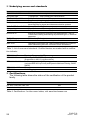
1
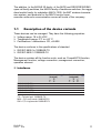
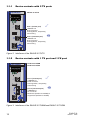
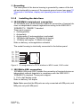
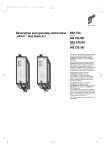
User Manual Installation Industrial ETHERNET Firewall EAGLE 20 V.24 EAGLE 20 TX/TX 09/08 2 V.24 2 1 R FAULT STATUS 2 V.24 IP-ADDRESS k IP-ADDRESS 2 g V.24 EAGLE 20 TX/MM EAGLE 20 TX/SM USB V.24 EAGLE 20 MM/TX Aufkleber MAC-Adresse USB 2 g +24V (P1) g Aufkleber MAC-Adresse 2 1 FAULT Aufkleber MAC-Adresse 1 FAULT k IP-ADDRESS LS/DA +24V (P2) 1 R P1 FAULT STATUS +24V (P1) FAULT 0V 0V +24V (P1) g +24V (P1) 2 USB +24V (P2) USB Release 2 1 Aufkleber MAC-Adresse 1 EAGLE 20 LS/DA 2 V.24 k IP-ADDRESS k 1 R P1 FAULT STATUS +24V (P2) 2 V.24 2 0V 0V LS/DA FAULT 1 R P1 FAULT STATUS +24V (P2) 2 0V 0V P1 LS/DA EAGLE 20 EAGLE 20 0V 0V EAGLE 20 EAGLE 20 V.24 EAGLE 20 MM/MM Technical support [email protected] The naming of copyrighted trademarks in this manual, even when not specially indicated, should not be taken to mean that these names may be considered as free in the sense of the trademark and tradename protection law and hence that they may be freely used by anyone. © 2008 Hirschmann Automation and Control GmbH Manuals and software are protected by copyright. All rights reserved. The copying, reproduction, translation, conversion into any electronic medium or machine scannable form is not permitted, either in whole or in part. An exception is the preparation of a backup copy of the software for your own use. For devices with embedded software, the end-user license agreement on the enclosed CD applies. The performance features described here are binding only if they have been expressly guaranteed in the contract. This publication has been created by Hirschmann Automation and Control GmbH according to the best of our knowledge. Hirschmann reserves the right to change the contents of this manual without prior notice. Hirschmann can give no guarantee in respect of the correctness or accuracy of the details in this publication. Hirschmann can accept no responsibility for damages, resulting from the use of the network components or the associated operating software. In addition, we refer to the conditions of use specified in the license contract. Printed in Germany Hirschmann Automation and Control GmbH Stuttgarter Str. 45-51 72654 Neckartenzlingen Germany Tel.: +49 1805 141538 039 715-001-01-0908 – 19.9.08 Content Safety instructions 4 About this manual 8 Legend 8 1 Device description 9 1.1 Description of the device variants 1.1.1 Device variants with 2 TX ports 1.1.2 Device variants with 1 TX port and 1 FX port 1.1.3 Device variants with 1 FX port and 1 TX port 1.1.4 Device variants with 2 FX ports 11 12 12 13 13 2 Assembly and start-up 14 2.1 Installing the device 2.1.1 Unpacking and checking 2.1.2 Terminal block for supply voltage and signal contact 2.1.3 Connecting the terminal block, start-up procedure 2.1.4 Installing the device on the hat-rail hub, grounding 2.1.5 Installing the data lines 14 14 14 16 16 17 2.2 Display elements 18 2.4 Making basic settings 20 2.6 Disassembly 24 3 Technical data 25 EAGLE 20 Release 09/08 3 Safety instructions This documentation contains instructions which must be observed to ensure your own personal safety and to avoid damage to devices and machinery. Certified usage Please observe the following: The device may only be employed for the purposes described in the catalog and technical description, and only in conjunction with external devices and components recommended or approved by the manufacturer. The product can only be operated correctly and safely if it is transported, stored, installed and assembled properly and correctly. Furthermore, it must be operated and serviced carefully. Password security note This device is a security-relevant product. For your own security, change the password during the first startup procedure. Supply voltage The devices are designed for operation with a safety extra-low voltage.Thus, they may only be connected to the supply voltage connections and to the signal contact with SELV circuits with the voltage restrictions in accordance with IEC/EN 60950-1.The supply voltage is electrically isolated from the housing. The supply voltage is electrically isolated from the housing. Use only undamaged parts! Relevant for North America: The subject unit is to be suppplied by a Class 2 power source complying with the requirements of the National Electrical Code, table 11(b). If power is redundant supplied (two individual power sources) the power sources together should comply with the requirements of the National Electrical Code, table 11 (b). Relevant for North America: Use 60/75°C or 75°C copper(CU)wire only. Shielding ground The shielding ground of the connectable twisted pairs lines is connected to the front panel as a conductor. Beware of possible short circuits when connecting a cable section with conductive shielding braiding. Housing Only technicians authorized by Hirschmann are permitted to open the housing. The lower panel of the device is grounded by means of the hat rail and optionally by means of the separate ground screw. 4 EAGLE 20 Release 09/08 Make sure that the electrical installation meets local or nationally applicable safety regulations. The ventilation slits must not be covered so as to ensure free air circulation. The clearance to the ventilation slits of the housing must be at least 10 cm. Never insert pointed objects (thin screwdrivers, wires, etc.) into the inside of the subrack! Failure to observe this point may result in injuries caused by electric shocks. The device must be installed in the vertical position (see fig. 8). If installed in a living area or office environment, the device must be operated exclusively in switch cabinets with fire protection characteristics according to EN 60950-1. Environment The device may only be operated at the specified maximum ambient temperature and relative air humidity (non-condensing). Install the device in a location where the climatic threshold values specified in the technical data are adhered to. Only to be used in an environment with the contamination level specified in the technical data. Qualification requirements for personnel Qualified personnel as understood in this manual and the warning signs, are persons who are familiar with the setup, assembly, startup, and operation of this product and are appropriately qualified for their job. This includes, for example, those persons who have been: X trained or directed or authorized to switch on and off, to ground and to label power circuits and devices or systems in accordance with current safety engineering standards; X trained or directed in the care and use of appropriate safety equipment in accordance with the current standards of safety engineering; X trained in providing first aid. General safety instructions This device is electrically operated. Adhere strictly to the safety requirements relating to voltages applied to the device as described in the operating instructions! Non-observance of these safety instructions can therefore cause material damage and/or serious injuries. EAGLE 20 Release 09/08 5 Only appropriately qualified personnel should work on this device or in its vicinity. These personnel must be thoroughly familiar with all the warnings and maintenance procedures in accordance with this operating manual. The proper and safe operation of this device depends on proper handling during transport, proper storage and assembly, and conscientious operation and maintenance procedures. Never start operation with damaged components! Only use the devices in accordance with this manual. In particular, observe all warnings and safety-related information. Any work that may be required on the electrical installation may only be carried out by personnel trained for this purpose. Warning! LED- or LASER components according to IEC 60825-1 (2001): CLASS 1 LASER PRODUCT. LIGHT EMITTING DIODE - CLASS 1 LED PRODUCT. National and international safety regulations Make sure that the electrical installation meets local or nationally applicable safety regulations. Note on the CE marking The devices comply with the regulations contained in the following European directives: 2004/108/EG Directive of the European Parliament and the Council for standardizing the regulations of member states on electromagnetic compatibility. In accordance with the above-named EU directives, the EU conformity declaration will be at the disposal of the relevant authorities at the following address: Hirschmann Automation and Control GmbH Stuttgarter Str. 45-51 72654 Neckartenzlingen Tel.: +49 1805 141538 The product can be used in living areas (living area, place of business, small business) and in industrial areas. X Interference immunity: EN 61000-6-2:2005 X Emitted interference: EN 55022:2006 Class A 6 EAGLE 20 Release 09/08 Warning! This is a class A device. This device can cause interference in living areas, and in this case the operator may be required to take appropriate measures. The assembly guidelines provided in these instructions must be strictly adhered to in order to observe the EMC value limits. FCC note: Appropriate testing has established that this device fulfills the requirements of a class A digital device in line with part 15 of the FCC regulations. These requirements are designed to provide sufficient protection against interference when the device is being used in a business environment. The device creates and uses high frequencies and can radiate same, and if it is not installed and used in accordance with this operating manual, it can cause radio transmission interference. The use of this device in a living area can also cause interference, and in this case the user is obliged to cover the costs of removing the interference. Recycling note After usage, this product must be disposed of properly as electronic waste in accordance with the current disposal regulations of your county / state / country. EAGLE 20 Release 09/08 7 About this manual The following manuals are available as PDF files on the CD-ROM supplied: X X X X “Installation” user manual “Configuration” user manual “Web-based Interface” reference manual and “Command Line Interface” reference manual Legend The commendations used in this manual have the following meanings: X 8 Listing Work step Subheading EAGLE 20 Release 09/08 1 Device description The industrial Firewall/VPN system X EAGLE 20 TX/TX X EAGLE 20 TX/MM X EAGLE 20 TX/SM X EAGLE 20 MM/TX X EAGLE 20 MM/MM subsequently known as EAGLE 20, ensures the authentication, security and confidentiality of communication within production networks, but also beyond company boundaries. The EAGLE 20 has the following interfaces: X depending on the type, up to two 10/100 Mbit/s twisted pair (TP/TX) ports (RJ45 socket) and/or X depending on the type, up to two 100 Mbit/s FX ports (multimode or singlemode) with DSC connections and X additionally a V.24 input for external management or a modem connection and X a USB interface. The EAGLE 20 supports the following network modes: X Transparent Mode X Router Mode The Industrial ETHERNET Firewall is used everywhere that securitysensitive network cells require a connection out from the cell in a harsh environment. The Industrial ETHERNET Firewall is the link between the “secure” network cells and the “unsecured outside world”. In its function as a link, the Industrial ETHERNET Firewall protects the security-sensitive cell from undesired data traffic along the connection to the outside world. Typical uses are: X X X X X Protecting individual production cells in a flat company network. Protecting individual production cells in a routed company network. Coupling identical production cells to a company network. Connecting a production cell with the office network via a public network. Providing protected service access. EAGLE 20 Release 09/08 9 6-pin terminal block, pluggable EAGLE 20 P1 LS/DA 2 1 R LED display elements FAULT STATUS 2 V.24 Reset button IP-ADDRESS k IP address field USB Aufkleber MAC-Adresse 1 2 g Port 1 and 2: Depending on device model TX (RJ45 connector) and/or FX (SC connector) V.24 FAULT +24V (P2) 0V 0V +24V (P1) MAC address field V.24 interface external management and modem Grounding screw Figure 1: Overview of interfaces, display and operating elements on the EAGLE 20 The devices are designed for the special requirements of industrial automation. They meet the relevant industry standards, provide very high operational reliability, even under extreme conditions, and also long-term reliability and flexibility. The devices operate without fans and have a redundant voltage supply. The devices are very quickly mounted by snapping them onto a hat rail, which also automatically contacts the function ground. The devices provide you with a large range of features: X Firewall (FW) X Virtual Private Network (VPN) functions X ARP Limiter X Redundancy support X ACA 21-USB support X Management: HTTPS, SNMPv1, SNMPv2, SNMPv3, SSH X Redundant power supply X Temperature range: 0°C – 60°C, without fan X Housing: mountable on hat rail, IP20 10 EAGLE 20 Release 09/08 The addition, to the EAGLE 20 family, of the MICE and RS20/RS30/RS40 open rail family switches, the MACH family of backbone switches, the ruggedized switch family for substation MACH 1000, the BAT wireless transmission system, and products for the MACH control room, ensures continuous communication across all levels of the company. 1.1 Description of the device variants These devices can be managed. They have the following properties: X Voltage range: 18 to 32 VDC X Temperature range: 0°C to +60 °C X Certifications / declarations: CE, cUL508 The device conforms to the specifications of standard X ISO/IEC 8802-3u 100BASE-TX X ISO/IEC 8802-3 100BASE-FX The device contains all the function units, such as: Firewall/VPN function, Management function, voltage connection, management connection, operation element. Interfaces EAGLE 20 TX/TX EAGLE 20 TX/MM EAGLE 20 TX/SM EAGLE 20 MM/TX EAGLE 20 MM/MM x x x g SM Port 2 (untrusted) MM k TX MM TX Port 1 (trusted) x x x x x x x TX = Twisted pair 100BASE-TX MM = F/O multimode 100BASE-FX SM = F/O singlemode 100BASE-FX EAGLE 20 Release 09/08 11 1.1.1 Device variants with 2 TX ports EAGLE 20 TX/TX EAGLE 20 P1 LS/DA 2 FAULT STATUS 2 V.24 1 R k IP-ADDRESS k USB 2 FAULT 0V 0V +24V (P1) g +24V (P2) Aufkleber MAC-Adresse 1 Port 1 (trusted port) 100BASE-TX RJ45 connector Autonegotiaton, autopolarity, autocrossing Port 2 (untrusted port) 100BASE-TX RJ45 connector Autonegotiaton, autopolarity, autocrossing g V.24 Figure 2: Interfaces of the EAGLE 20 TX/TX 1.1.2 Device variants with 1 TX port and 1 FX port EAGLE 20 TX/MM EAGLE 20 TX/SM EAGLE 20 P1 LS/DA 2 1 R FAULT STATUS 2 V.24 k IP-ADDRESS k 2 FAULT 0V 0V +24V (P1) g +24V (P2) USB Aufkleber MAC-Adresse 1 Port 1 (trusted port) 100BASE-TX RJ45 connector Autonegotiaton, autopolarity, autocrossing g Port 2 (untrusted port) 100BASE-FX SC connector Multimode (EAGLE 20 TX/MM) or singlemode (EAGLE 20 TX/SM) V.24 Figure 3: Interfaces of the EAGLE 20 TX/MM and EAGLE 20 TX/SM 12 EAGLE 20 Release 09/08 1.1.3 Device variants with 1 FX port and 1 TX port EAGLE 20 MM/TX EAGLE 20 P1 LS/DA 2 FAULT STATUS 2 V.24 1 R IP-ADDRESS k USB 2 FAULT 0V 0V +24V (P1) g +24V (P2) Aufkleber MAC-Adresse 1 Port 1 (trusted port) 100BASE-FX SC connector Multimode k Port 2 (untrusted port) 100BASE-TX RJ45 connector Autonegotiaton, autopolarity, autocrossing g V.24 Figure 4: Interfaces of the EAGLE 20 MM/TX 1.1.4 Device variants with 2 FX ports EAGLE 20 MM/MM EAGLE 20 P1 LS/DA 2 1 R FAULT STATUS 2 V.24 IP-ADDRESS k 2 FAULT 0V 0V +24V (P1) g +24V (P2) USB Aufkleber MAC-Adresse 1 Port 1 (trusted port) 100BASE-FX SC connector Multimode k Port 2 (untrusted port) 100BASE-FX SC connector Multimode g V.24 Figure 5: Interfaces of the EAGLE 20 MM/MM EAGLE 20 Release 09/08 13 2 Assembly and start-up The devices have been developed for practical application in a harsh industrial environment. The installation process is correspondingly simple. On delivery, the device is ready for operation. The following procedure has been proven to be successful for the assembly of the device: X Unpacking and checking X Connect the terminal block for voltage supply and signal contact and connect the supply voltage X Install the terminal block, start-up procedure X Install the device on the hat-rail hub, grounding X Install the data lines 2.1 Installing the device Before installing and starting up the device, note the safety instructions (see page 4). 2.1.1 Unpacking and checking Check whether the contents of the package are complete (see page 27 "Scope of delivery"). Check the individual parts for transport damage. 2.1.2 Terminal block for supply voltage and signal contact The supply voltage and the signal contact are connected via a 6-pin terminal block with a snap lock. Supply voltage The supply voltage can be connected redundantly. Both inputs are uncoupled. There is no distributed load. With redundant supply, the power supply unit supplies the Switch alone with the higher output voltage. The supply voltage is electrically isolated from the housing. You can choose between DC or AC voltage when connecting the supply voltage. You use the +24V and 0V pins to connect the AC voltage ((see fig. 6), (see fig. 7)). 14 EAGLE 20 Release 09/08 Note: With non-redundant supply of the mains voltage, the device reports a power failure. You can prevent this message by applying the supply voltage via both inputs, or by changing the configuration in the Management. Warning The devices are designed for operation with a safety extra-low voltage.Thus, they may only be connected to the supply voltage connections and to the signal contact with SELV circuits with the voltage restrictions in accordance with IEC/EN 60950-1.The supply voltage is electrically isolated from the housing. FAULT +24V(P1) 0V + 9,6...60 VDC 0V +24V(P2) + 9,6...60 VDC Figure 6: Pin assignment of the 6-pin terminal block, DC connection FAULT +24V(P1) 0V 0V +24V(P2) G G 18...30 VAC 18...30 VAC Figure 7: Pin assignment of the 6-pin terminal block, AC connection Signal contacts X The signal contacts are used for the remote monitoring of the device to enable remote diagnostics. You can specify the type of function monitoring in the Management. X You can also use the Management to set the signal contact manually and thus control external devices. A break in contact is used to report the following conditions via the potential-free signal contact (relay contact, closed circuit): X The failure of at least one of the two voltage supplies (voltage supply 1 or 2 is below the threshold value). X A continuous malfunction in the device (internal supply voltage). EAGLE 20 Release 09/08 15 X The defective link status of at least one port. The report of the link status can be masked by the Management for each port. In the delivery state, link status monitoring is deactivated. X The temperature threshold has been exceeded or has not been reached. X The removal of the ACA. 2.1.3 Connecting the terminal block, start-up procedure Pull the terminal block off the device and connect the voltage supply lines and the signal lines. Startup procedure Mount the terminal block for the voltage supply and signal contact on the front of the device using the snap lock. Make sure that the snap lock snaps into place. By connecting the voltage supply via the terminal block, you start the operation of the device. 2.1.4 Installing the device on the hat-rail hub, grounding Mount the device on a 35 mm hat rail in accordance with DIN EN 60175. Attach the upper snap-in guide of the device into the hat rail and press it down against the hat rail until it snaps into place. Note: The shielding ground of the industrial connectable twisted pair lines is connected to the lower panel as a conductor. Figure 8: Mounting on the hat rails 16 EAGLE 20 Release 09/08 Grounding The lower panel of the device housing is grounded by means of the hat rail and optionally by means of the separate ground screw (see page 10 "Overview of interfaces, display and operating elements on the EAGLE 20"). 2.1.5 Installing the data lines 10/100 Mbit/s twisted pair connection 10/100 Mbit/s ports (RJ45 sockets) enable the connection of terminal devices or independent network segments according to the IEEE 802.3 100BASE-TX / 10BASE-T standard. These ports support: X Autonegotiation X Autopolarity X Autocrossing (if autonegotiation is activated) X 100 Mbit/s half duplex, 100 Mbit/s full duplex, X 10 Mbit/s half duplex, 10 Mbit/s full duplex. State on delivery: autonegotiation activated The socket housing is electrically connected to the bottom panel. n.c. n.c. TDn.c. n.c. TD+ RDRD+ Pin 8 Pin 7 Pin 6 Pin 5 Pin 4 Pin 3 Pin 2 Pin 1 Figure 9: Pin assignment of a TP/TX interface in MDI-X mode, RJ45 socket 100 Mbit/s-LWL connection 100 MBit/s LWL ports (DSC) enable the connection of terminal devices or independent network segments in compliance with the IEEE 802.3 100BASE-FX standard. These ports support: X Full or half duplex mode State on delivery: full duplex Note: Make sure that the SM ports are only connected with SM ports, and MM ports only with MM ports. EAGLE 20 Release 09/08 17 2.1.6 Connection to the network Connect the device to the local network or the local computer that you want to protect (k). Connect the socket for the connection to the external (non-secure) network (g), e.g. the Internet. (This network is used to set up the connections to the remote device or the remote network.) 2.2 Display elements After the operating voltage is set up, the software starts and initializes itself. Afterwards, the device performs a self-test. During these actions, the STATUS LED flashes. The process takes around 60 seconds. P 1 2 FAULT STATUS LS/DA 1 2 V.24 Device state These LEDs provide information about conditions which affect the operation of the whole device. P1 - Power 1 (green LED) Glowing green Not glowing P2 - Power 2 (green LED) Glowing green Not glowing FAULT - error, signal contact (red LED) Glowing red Not glowing STATUS (green/yellow LED) Flashing green Glowing green Slowly flashing yellow STATUS and V.24 - saving processes of the AutoConfiguration Adapter (ACA) Flashing alternately LEDs flash synchronously, two times a second LEDs flash synchronously, once a second 18 Supply voltage 1 is present. Supply voltage 1 is less than 18 V. Supply voltage 2 is present. Supply voltage 2 is less than 18 V. The signal contact is open, i.e. it is reporting an error. The signal contact is closed, i.e. it is not reporting an error. Initialization phase of the device. Device is ready for operation. The device is in Router Redundancy Backup Mode. Error during saving process. Loading configuration from the ACA. Saving the configuration in the ACA. EAGLE 20 Release 09/08 If the manual adjustment is active on the signal contact, then the error display is independent of the setting of the signal contact. Port status These LEDs display port-related information. LS/DA, V.24 - data, link status (green/yellow LEDs) Not glowing Glowing green Flashing green (3 times a period) Flashing yellow 2.3 Meaning No valid connection. Valid connection. Port is switched off. Data reception. Controls The EAGLE 20 has a Reset button (see page 10 "Overview of interfaces, display and operating elements on the EAGLE 20"). Reset button R (restart) The reset button is used to restart the device. To perform the restart, press the reset button for longer than 1.5 seconds until the STATUS LED goes out and the FAULT LED lights up red. Note: The system monitor is used to flash the software. You will find a more detailed description of how to perform this action in the “Configuration” user manual of the EAGLE 20. EAGLE 20 Release 09/08 19 2.4 Making basic settings The IP parameters must be entered when the device is installed for the first time. The device provides multiple options for configuring IP addresses: X Entry via V.24 connection X Entry via the HiDiscovery protocol (via the internal port) X Auto Configuration Adapter Further information on the basic settings of the device can be found in the "Basic Configuration" user manual on the CD ROM. State on delivery X IP address: DHCP default setting off X Management password: user, password: public (read only) admin, password: private (read and write) X V.24 data rate: 9,600 Baud X Ethernet ports: link status is not evaluated (signal contact) X Optical 100 Mbit/s ports: 100 Mbit/s full duplex All other ports: autonegotiation USB interface The USB socket has an interface for the local connection of an AutoConfiguration Adapter ACA 21-USB. It is used for saving/loading the configuration and for loading the software. Contact number 1 2 3 4 Signal name VCC - Data + Data Ground V.24 interface (external management) A serial interface is provided on the RJ11 socket (V.24 interface) for the local connection of an external management station (VT100 terminal or PC with corresponding terminal emulation). This enables you to set up a connection to the Command Line Interface (CLI) and to the system monitor. VT 100 terminal settings Speed Data Stopbit Handshake Parity 20 9,600 Baud 8 bit 1 bit off none EAGLE 20 Release 09/08 The socket housing is electrically connected to the front panel of the device. The V.24 interface is not electrically isolated from the supply voltage. RJ11 DB9 Pin 5 Pin 8 Pin 6 Pin 1 Pin 1 CTS n.c. TX GND RX RTS 1 2 3 4 5 6 2 3 5 Figure 10: Pin assignment of the V.24 interface Note: You will find the order number for the terminal cable, which is ordered separately, in the Technical Data chapter (see on page 25 "Technical data"). 2.5 Configuration 2.5.1 Firewall and VPN functions Firewall functions The EAGLE 20 supports the following firewall functions: X Stateful Inspection Firewall X Transparent Firewall X Configurable Firewall rules: X Incoming/outgoing data traffic X Modem access X External Management access X IP Masquerading, 1-to-1 NAT, port forwarding X IP Spoofing Protection VPN functions The EAGLE 20 supports the following Virtual Private Network (VPN) functions: X Multipoint VPN: Router Mode X VPN protocols: IPsec X Encryption algorithms: EAGLE 20 Release 09/08 21 X DES-56 X 3DES-168 X AES-128, AES-192, AES-256 X Authentication: X Pre-shared key (PSK) X X.509v3 certificates X Hashing algorithms: MD5, SHA-1 X NAT-T support 2.5.2 Operating modes This device protects the network to be secured (secure port k) from external influences (non-secure port g). These influences can include deliberate attacks or unauthorized access attempts, as well as interfering network events such as overloads. State on delivery On delivery, the device works in the Transparent Mode. In this mode, no network settings (e.g., for subnetworks) are required for operation. The firewall has been preconfigured so that all IP traffic from the secure network (k) is possible; however, traffic from the non-secure network (g) to the secure one is not possible. Thus, already in the delivery state, external attacks on the secure network are not possible. Transparent Mode The Transparent Mode is a transparent bridge mode. In this mode, the device works as a 2-port bridge, whereby only IP and ARP frames corresponding to the firewall rules are transmitted. In the state on delivery, you can access the device via address 192.168.1.1/24 without configuring the IP address. Router Mode In Router Mode, the device works as a 2-port router. You will find a detailed description of the IP configuration in the “Basic Configuration” user manual of the EAGLE 20. Note: In the Router and Transparent modes, an additional network access option to the secure network is provided over the V.24 interface of the EAGLE 20, via PPP. In this case, communication is possible with the EAGLE 20 itself or with the devices in the secure network (according to the firewall rules for the modem connection). 22 EAGLE 20 Release 09/08 PPPoE Mode In PPPoE Mode, the EAGLE 20 works like in the router mode, with the difference that the PPPoE protocol is used at the external port. This enables Internet connections via a DSL modem, for example. 2.5.3 Start configuration To access the EAGLE 20, you proceed as follows (device in state on delivery): Make sure that the required Java plug-in is installed on your computer. You will find information about the plug-in and its installation in the Configuration user manual. Start an https-capable Web browser on the computer connected to the secure port (e.g. Mozilla Firefox from version 1 on, or Microsoft Internet Explorer from version 6 on) in order to configure the EAGLE 20. Connect the non-secure port to your network. Enter the following address in the Web browser: https://192.168.1.1/ Result: The HTTPS connection to the EAGLE 20 is set up. A security warning is displayed. Confirm the security warning with “Yes”. To login, enter: – Login: admin – Password: private (case-sensitive!) Result: The Administrator website of the EAGLE 20 is displayed. Configure the device in accordance with the Configuration user manual. Alternatively, you can perform the IP configuration for the Transparent Mode using the HiDiscovery protocol. You will find the HiDiscovery software in the CD ROM included in the delivery. Note: If the configuration connection to the EAGLE 20 is not set up, you will find detailed information in the “Configuration User Manual - Industrial ETHERNET Firewall EAGLE 20”. EAGLE 20 Release 09/08 23 Figure 11: Configuration before the installation of the EAGLE 20 x EAGLE P 1 2 FAULT STATUS LS/DA 1 2 V.24 R IP-ADDRESS k 1 2 +24V (P2) Aufkleber MAC-Adresse +24V (P1) 0V 0V FAULT g V.24 Figure 12: Configuration after the installation of the EAGLE 20 2.6 Disassembly Disassembling the device In order to remove the device from the hat rail, move the screwdriver horizontally under the chassis in the locking gate, pull this down - without tilting the screwdriver - and fold the device up. Figure 13: Disassembly 24 EAGLE 20 Release 09/08 3 Technical data General technical data Dimensions WxHxD Weight EAGLE 20... 46 mm x 131 mm x 111 mm EAGLE 20... 340 g Power supply Operating voltage 18 to 60 V DC Safety extra-low voltage (SELV/PELV) redundant inputs disconnected. Relevant for North America: Nec Class 2 power source max. 5A. Non-replaceable fuse Overload current protection at input Insulation voltage between operating voltage connections and housing Signal contact Environment Storage temperature (ambient air temperature) Humidity Atmospheric pressure Operating temper- Ambient air ature Contamination level Protection classes Laser protection Protection class 800 V DC Protective elements limit the insulation voltage to: 90 V DC (1 mA). max. 1 A, 60 V DC or 30 V AC -40 °C to +70 °C 10% to 95% (non-condensing) Up to 2000 m (795 hPa), higher altitudes on request 0 °C to +60 °C 2 Class 1 according to EN 60825-1 (2001) IP 20 EMC and immunity EMC interference immunity EN 61000-4-2 EN 61000-4-3 EN 61000-4-4 EN 61000-4-5 EN 61000-4-6 EN 61000-4-9 EAGLE 20 Release 09/08 Electrostatic discharge Contact discharge Air discharge Electromagnetic field 80 - 2,700 MHz Fast transients (burst) - Power line - Data line Voltage surges - Power line, line/line - Power line, line/earth - Data line Line-conducted interference voltages 150 kHz - 80 MHz Impulse-shaped magnetic fields 4 kV 8 KV 10 V/m 2 kV 1 kV 0.5 kV 1 kV 1 kV 10 V - 25 EMC emitted interference EN 55022 FCC 47 CFR Part 15 Germanischer Lloyd Stability Vibration Shock Class A Class A Classification and Construction Guidelines VI-7-3 Part 1 Yes Yes - IEC 60068-2-6 Test FC test level according to IEC 61131-2 Germanischer Lloyd Guidelines for the Performance of Type Tests Part 1 IEC 870-2-2 table 3 normal, requirements according to EN61850-3 EN 61373, Category 1, Class A (broadband noise), requirements according to EN 50155 IEC 60068-2-27 Test Ea test level according to IEC 61131-2 IEC 870-2-2 table 3 normal, requirements according to EN61850-3 EN 61373, Category 1, Class A requirements according to EN 50155 Yes Yes - Network range TP port Length of a twisted pair segment max. 100 m Table 1: TP port 10BASE-T / 100BASE-TX LWL Port MM MM SM Wavelength Fiber System attenuation 1300 nm 50/125 µm 0-8 dB 1300 nm 62.5/125 µm 0-11 dB 1300 nm 9/125 µm 0-16 dB Expansion Fiber data 0-5 km 1.0 dB/km, 800 MHz*km 0-4 km 1.0 dB/km, 500 MHz*km 0-30 km 0.4 dB/km; 3.5 ps/(nm*km) Table 2: LWL port 100BASE-FX MM = multimode SM = singlemode Power consumption/power output Device Power consumption at 24 V DC EAGLE 20 with 2 TX ports 6.9 W EAGLE 20 with 1 TX port 8.1 W and 1 FX port EAGLE 20 with 2 FX ports 9.5 W 26 Power output at 24 V DC 23.5 Btu (IT)/h 27.6 Btu (IT)/h Power consumption at 24 V AC 7.2 W 8.1 W Power output at 24 V AC 24.6 Btu (IT)/h 27.6 Btu (IT)/h 32.4 Btu (IT)/h 9.6 W 32.8 Btu (IT)/h EAGLE 20 Release 09/08 Order numbers Device EAGLE 20 TX/TX EAGLE 20 TX/MM EAGLE 20 TX/SM EAGLE 20 MM/TX EAGLE 20 MM/MM Order number 943 987-001 943 987-002 943 987-003 943 987-004 943 987-005 Interfaces EAGLE 20... V.24 port: external management, modem terminal block, 6-pin: signal contact, max. 1 A, 24 V and voltage supply USB interface: ACA 21-USB Additionally 2 type-depen- Up to two 10/100 Mbit/s twisted pair (TP/TX) ports with RJ45 sockdent ports each ets and/or up to two 100 Mbit/s FX ports (multimode or singlemode) with DSC connections Scope of delivery Device EAGLE 20... Scope of delivery EAGLE 20... device Terminal block for supply voltage and signal contact (6-pin) CD ROM with user manual Installation user manual Accessories Note: Please note that products recommended as accessories may have characteristics that do not fully correspond to those of the corresponding product. This may limit their possible usage in the overall system. Name Pocket Guide AutoConfiguration Adapter ACA 21-USB Terminal cable 6-pin terminal block Rail Power Supply RPS 30 Rail Power Supply RPS 80 EEC Rail Power Supply RPS 120 EEC Industrial HiVision Network Management software EAGLE 20 Release 09/08 Order number 280 710-851 943 271-001 943 301-001 943 845-002 943 662-003 943 662-080 943 662-120 943 156-xxx 27 Underlying norms and standards Name EN 61000-6-2:2005 EN 55022:2006 IEC/EN 60950-1:2006 EN 61131-2:2003 EN 50121-4:2000 FCC 47 CFR Part 15:2006 German Lloyd cUL 508:1998 EN 60079-15 EN 50155 IEC/EN 61850-3 IEEE 1613 Generic norm – immunity in industrial environments IT equipment – radio interference characteristics Safety for the installation of IT equipment Programmable logic controllers Railway applications - EMC - emitted interference and interference immunity for signal and telecommunication systems Code of Federal Regulations Classification and Construction Guidelines VI-7-3 Part 1 Ed.2003 Safety for Industrial Control Equipment Electrical equipment for explosive gas atmospheres – part 15: Construction, testing and marking of protection type "n" electrical apparatus. Declaration (Railway) Communications networks and systems in stations Standard Environment and Testing Requirements for Communication Networking Devices in Electric Power Substations Table 3: List of norms and standards. Certified devices are marked with a certification indicator. IEEE 802.1 AB IEEE 802.1 D IEEE 802.1 D-1998 IEEE 802.3 - 2002 IEEE 802.3 ac Topology Discovery (LLDP) Switching, GARP, GMRP, Spanning Tree (Supported via 802.1S implementation) Media access control (MAC) bridges (includes IEEE 802.1p Priority and Dynamic Multicast Filtering, GARP, GMRP) Ethernet VLAN Tagging Certifications The following table shows the status of the certification of the product family. Standard cUL 508 / CSA C22.2 No.142 Germanischer Lloyd Yes Yes Table 4: Certifications - for the current status, visit www.hirschmann.com 28 EAGLE 20 Release 09/08 Further support A Further support Technical questions and training courses In the event of technical queries, please talk to the Hirschmann contract partner responsible for looking after your account or directly to the Hirschmann office. You can find the addresses of our contract partners on the Internet: www.hirschmann.com. Our support line is also at your disposal: X Tel. +49 1805 14-1538 X Fax +49 7127 14-1551 Answers to Frequently Asked Questions can be found on the Hirschmann internet site (www.hirschmann.com) at the end oft the product sites in the FAQ category. The current training courses to technology and products can be found under http://www.hicomcenter.com. Hirschmann Competence Center In the long term, excellent products alone do not guarantee a successful customer relationship. Only comprehensive service makes a difference worldwide. In the current global competition scenario, the Hirschmann Competence Center is ahead of its competitors on three counts with its complete range of innovative services: X Consulting incorporates comprehensive technical advice, from system evaluation through network planning to project planing. X Training offers you an introduction to the basics, product briefing and user training with certification. X Support ranges from the first installation through the standby service to maintenance concepts. With the Hirschmann Competence Center, you have decided against making any compromises. Our client-customized package leaves you free to choose the service components you want to use. Internet: http://www.hicomcenter.com. EAGLE 20 Release 09/08 29