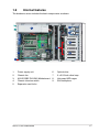
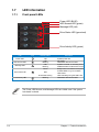
Download TS700-E4/RX8 Server
Transcript
TS700-E4/RX8 Server Pedestal/5U Rackmount Server User's Manual E3008 First edition V1 January 2007 Copyright © 2007 ASUSTeK COMPUTER INC. All Rights Reserved. No part of this manual, including the products and software described in it, may be reproduced, transmitted, transcribed, stored in a retrieval system, or translated into any language in any form or by any means, except documentation kept by the purchaser for backup purposes, without the express written permission of ASUSTeK COMPUTER INC. (“ASUS”). ASUS provides this manual “as is” without warranty of any kind, either express or implied, including but not limited to the implied warranties or conditions of merchantability or fitness for a particular purpose. In no event shall ASUS, its directors, officers, employees, or agents be liable for any indirect, special, incidental, or consequential damages (including damages for loss of profits, loss of business, loss of use or data, interruption of business and the like), even if ASUS has been advised of the possibility of such damages arising from any defect or error in this manual or product. Specifications and information contained in this manual ae furnished for informational use only, and are subject to change at any time without notice, and should not be construed as a commitment by ASUS. ASUS assumes no responsibility or liability for any errors or inaccuracies that may appear in this manual, including the products and software described in it. Product warranty or service will not be extended if: (1) the product is repaired, modified or altered, unless such repair, modification of alteration is authorized in writing by ASUS; or (2) the serial number of the product is defaced or missing. Products and corporate names appearing in this manual may or may not be registered trademarks or copyrights of their respective companies, and are used only for identification or explanation and to the owners’ benefit, without intent to infringe. ii Contents Contents....................................................................................................... iii Notices......................................................................................................... vii Safety information..................................................................................... viii About this guide.......................................................................................... ix Chapter 1: Product introduction Chapter 2: Hardware setup 1.1 1.2 1.3 1.4 1.5 1.6 1.7 2.1 2.2 2.3 2.4 2.5 2.6 2.7 2.8 System package contents............................................................ 1-2 System specifications.................................................................. 1-3 Serial number label....................................................................... 1-4 Front panel features...................................................................... 1-5 Rear panel features....................................................................... 1-6 Internal features............................................................................ 1-7 LED information............................................................................ 1-8 1.7.1 Front panel LEDs............................................................. 1-8 1.7.2 Rear panel LEDs.............................................................. 1-9 Chassis cover................................................................................ 2-2 2.1.1 Removing the side cover................................................. 2-2 2.1.2 Reinstalling the side cover............................................... 2-3 Motherboard information............................................................. 2-4 Central Processing Unit (CPU).................................................... 2-5 2.3.1 Installing the CPU............................................................ 2-5 2.3.2 Installing the CPU heatsink.............................................. 2-8 System memory............................................................................ 2-9 Overview.......................................................................... 2-9 2.4.1 2.4.2 Memory configurations..................................................... 2-9 2.4.3 Memory mirroring and sparing technology......................2-11 2.4.4 Installing a DIMM........................................................... 2-15 2.4.5 Removing a DIMM......................................................... 2-15 Front panel assembly................................................................. 2-16 2.5.1 Removing the front panel assembly............................... 2-16 2.5.2 Reinstalling the front panel assembly............................ 2-18 5.25-inch drives........................................................................... 2-19 Hard disk drives.......................................................................... 2-22 2.7.1 Installing a hot-swap SATA/SAS HDD........................... 2-22 2.7.2 Installing an HDD dummy cover.................................... 2-24 Expansion cards......................................................................... 2-25 2.8.1 Installing an expansion card.......................................... 2-25 2.8.2 Removing an expansion card........................................ 2-26 iii 2.9 2.10 Cable connections...................................................................... 2-27 2.9.1 Motherboard layouts...................................................... 2-27 2.9.2 SAS backplane connections.......................................... 2-28 Removable components............................................................. 2-31 2.10.1 Rear fan......................................................................... 2-31 2.10.2 System fan..................................................................... 2-33 2.10.3 SAS backplane.............................................................. 2-36 2.10.4 MemCool FB-DIMM fan kit............................................. 2-38 2.10.5 Floppy disk drive............................................................ 2-41 2.10.6 Front I/O board............................................................... 2-43 2.10.7 Roller wheels................................................................. 2-45 2.10.8 Power supply unit........................................................... 2-46 Chapter 3: 3.1 3.2 3.3 3.4 Chapter 4: 4.1 4.2 4.3 iv Motherboard Info Motherboard layout....................................................................... 3-2 DSBF-D12/SAS model.................................................................... 3-2 Layout contents............................................................................... 3-3 Jumpers......................................................................................... 3-5 Switch........................................................................................... 3-10 Connectors.................................................................................. 3-11 3.4.1 Rear panel connectors....................................................3-11 3.4.2 Internal connectors........................................................ 3-12 BIOS setup Managing and updating your BIOS............................................. 4-2 4.1.1 Creating a bootable floppy disk........................................ 4-2 4.1.2 Updating the BIOS using the Phoenix Phlash16 Utility.... 4-3 4.1.3 ASUS CrashFree BIOS 2 utility....................................... 4-4 4.1.4 ASUS Update utility......................................................... 4-6 BIOS setup program..................................................................... 4-9 4.2.1 BIOS menu screen......................................................... 4-10 4.2.2 Menu bar........................................................................ 4-10 4.2.3 Legend bar......................................................................4-11 4.2.4 Menu items.....................................................................4-11 4.2.5 Sub-menu items..............................................................4-11 4.2.6 Configuration fields.........................................................4-11 4.2.7 Pop-up window.............................................................. 4-12 4.2.8 General help.................................................................. 4-12 Main menu................................................................................... 4-13 4.3.1 System Date [Day xx/xx/xxxx]........................................ 4-13 4.4 4.5 4.6 4.7 4.8 4.3.2 System Time [xx:xx:xx].................................................. 4-13 4.3.3 Floppy A [1.44M, 3½in.]................................................. 4-13 4.3.4 IDE Configuration........................................................... 4-14 4.3.5 IDE Channel 0 Master/Slave.......................................... 4-16 4.3.6 SATA Port 1/2/3/4........................................................... 4-17 4.3.7 System Information........................................................ 4-19 Advanced menu.......................................................................... 4-21 4.4.1 Advanced Processor Options........................................ 4-21 4.4.2 Chipset Configuration.................................................... 4-24 4.4.3 PCI Configuration........................................................... 4-27 4.4.4 ICH USB Control Sub-Menu.......................................... 4-29 4.4.5 Peripheral Devices Configuration.................................. 4-30 4.4.6 ACPI Configuration........................................................ 4-32 4.4.7 Power On Configuration................................................. 4-33 4.4.8 Hardware Monitor.......................................................... 4-34 Server menu................................................................................ 4-37 5.5.1 Console Redirection....................................................... 4-37 4.5.2 DMI Event Logging........................................................ 4-39 Security menu............................................................................. 4-40 Boot menu................................................................................... 4-42 4.7.1 Boot Device Priority....................................................... 4-42 4.7.2 Boot Features................................................................ 4-43 Exit menu..................................................................................... 4-44 Chapter 5: 5.1 5.2 Chapter 6: 6.1 RAID configuration Setting up RAID............................................................................. 5-2 5.1.1 RAID definitions............................................................... 5-2 5.1.2 Installing hard disk drives................................................. 5-3 5.1.3 Setting the RAID item in BIOS......................................... 5-3 5.1.4 RAID configuration utilities............................................... 5-3 LSI Logic MPT Setup Utility......................................................... 5-4 5.2.1 Integrated Mirroring.......................................................... 5-4 5.2.2 Integrated Mirroring Enhanced........................................ 5-8 5.2.3 Integrated Striping (IS) volume...................................... 5-10 5.2.4 Managing Arrays............................................................ 5-13 Viewing SAS topology.................................................... 5-18 5.2.5 5.2.6 Global Properties........................................................... 5-20 Driver installation RAID driver installation................................................................ 6-2 6.2 6.3 6.4 6.5 vi 6.1.1 Creating a RAID driver disk............................................. 6-2 6.1.2 Installing the RAID controller driver................................. 6-3 Intel® chipset software installation............................................ 6-12 LAN driver installation................................................................ 6-15 6.3.1 Windows 2000/Server 2003........................................... 6-15 6.3.2 Red Hat/SuSE Linux...................................................... 6-20 VGA driver installation............................................................... 6-21 6.4.1 Windows® 2000/Server 2003......................................... 6-21 Management applications and utilities installation................. 6-24 6.5.1 Running the support CD................................................ 6-24 6.5.2 Drivers menu.................................................................. 6-24 6.5.3 Management Software menu......................................... 6-25 6.5.4 Utilities menu................................................................. 6-25 6.5.5 Contact information........................................................ 6-25 Notices Federal Communications Commission Statement This device complies with Part 15 of the FCC Rules. Operation is subject to the following two conditions: • This device may not cause harmful interference, and • This device must accept any interference received including interference that may cause undesired operation. This equipment has been tested and found to comply with the limits for a Class B digital device, pursuant to Part 15 of the FCC Rules. These limits are designed to provide reasonable protection against harmful interference in a residential installation. This equipment generates, uses and can radiate radio frequency energy and, if not installed and used in accordance with manufacturer’ s instructions, may cause harmful interference to radio communications. However, there is no guarantee that interference will not occur in a particular installation. If this equipment does cause harmful interference to radio or television reception, which can be determined by turning the equipment off and on, the user is encouraged to try to correct the interference by one or more of the following measures: • Reorient or relocate the receiving antenna. • Increase the separation between the equipment and receiver. • Connect the equipment to an outlet on a circuit different from that to which the receiver is connected. • Consult the dealer or an experienced radio/TV technician for help. WARNING! The use of shielded cables for connection of the monitor to the graphics card is required to assure compliance with FCC regulations. Changes or modifications to this unit not expressly approved by the party responsible for compliance could void the user’s authority to operate this equipment. Canadian Department of Communications Statement This digital apparatus does not exceed the Class B limits for radio noise emissions from digital apparatus set out in the Radio Interference Regulations of the Canadian Department of Communications. This class B digital apparatus complies with Canadian ICES-003. vii Safety information Electrical safety • Before installing or removing signal cables, ensure that the power cables for the system unit and all attached devices are unplugged. • To prevent electrical shock hazard, disconnect the power cable from the electrical outlet before relocating the system. • When adding or removing any additional devices to or from the system, ensure that the power cables for the devices are unplugged before the signal cables are connected. If possible, disconnect all power cables from the existing system before you add a device. • If the power supply is broken, do not try to fix it by yourself. Contact a qualified service technician or your dealer. Operation safety • Any mechanical operation on this server must be conducted by certified or experienced engineers. • Before operating the server, carefully read all the manuals included with the server package. • Before using the server, make sure all cables are correctly connected and the power cables are not damaged. If any damage is detected, contact your dealer as soon as possible. • To avoid short circuits, keep paper clips, screws, and staples away from connectors, slots, sockets and circuitry. • Avoid dust, humidity, and temperature extremes. Place the server on a stable surface. This product is equipped with a three-wire power cable and plug for the user’s safety. Use the power cable with a properly grounded electrical outlet to avoid electrical shock. Lithium-Ion Battery Warning CAUTION! Danger of explosion if battery is incorrectly replaced. Replace only with the same or equivalent type recommended by the manufacturer. Dispose of used batteries according to the manufacturer’s instructions. CD-ROM Drive Safety Warning CLASS 1 LASER PRODUCT Heavy System CAUTION! This server system is heavy. Ask for assistance when moving or carrying the system. viii About this guide Audience This user guide is intended for system integrators and experienced users with at least basic knowledge of configuring a server. Contents This guide contains the following parts: 1. Chapter 1: Product Introduction This chapter describes the general features of the barebone server, including sections on the front panel and rear panel specifications. 2. Chapter 2: Hardware setup This chapter lists the hardware setup procedures that you have to perform when installing or removing system components. 3. Chapter 3: Motherboard information This chapter gives information about the motherboard that comes with the server. This chapter includes the motherboard layout, jumper settings, and connector locations. 4. Chapter 4: BIOS setup This chapter tells how to change the system settings through the BIOS Setup menus. Detailed descriptions of the BIOS parameters are also provided. 5. Chapter 5: RAID configuration This chapter tells how to change system settings through the BIOS Setup menus. Detailed descriptions of the BIOS parameters are also provided. 6. Chapter 6: Driver installation This chapter provides instructions for installing the necessary drivers for different system components. ix Conventions To make sure that you perform certain tasks properly, take note of the following symbols used throughout this manual. WARNING: Information to prevent injury to yourself when trying to complete a task. CAUTION: Information to prevent damage to the components when trying to complete a task. IMPORTANT: Instructions that you MUST follow to complete a task. NOTE: Tips and information to aid in completing a task. Reference 1. ASUS Server Web-based Management (ASWM) user guide This manual tells how to set up and use the proprietary ASUS server management utility. 2. ASUS websites The ASUS websites worldwide provide updated information for all ASUS hardware and software products. Refer to the ASUS contact information. This chapter describes the general features of the barebone server, including sections on the front panel and rear panel specifications. Product introduction Chapter 1 1- 1.1 System package contents Check your system package for the following items. Chassis Motherboard Components ASUS T70 5U rackmount chassis ASUS DSBF-D12/SAS motherboard 1 x 730W redundant power supply module 1 x power supply bay cover 1 x optical drive 1 x Floppy disk drive Chassis fan 1 x 12 cm rear fan 2 x 8025 system fan 2x 8038 CPU fan 2 x MemCool FB-DIMM fan kit 8 x Hot-swap HDD trays (including HDD screws) 2 x SAS/SATA backplane board (BP4LX-T30) 1 x Front panel board (FPB-AS25/2U) 2 x 5¼" Dummy Covers AC power cable Cables System cables 1 x USB cable 2 x SAS cables Accessories SMBus cable 2 x System keys TS700-E4/RX8 user guide TS700-E4/RX8 support CD (includes ASWM*) ASWM 2.0 user guide CA eTrust Anti-virus CD 4 x Chassis roller wheel sets Optional items One bag of screws Rackmount rail kit ASUS certified heatsink *ASUS System Web-based Management If any of the above items is damaged or missing, contact your retailer. 1- Chapter 1: Product introduction 1.2 System specifications The ASUS TS700-E4/RX8/RX8 is a 5U barebone server system featuring the ASUS DSBF-D12/SAS motherboard. The server supports dual Intel LGA771 Xeon processors with EM64T technology, plus other latest technologies through the chipsets onboard. Chassis Rackmount 5U Motherboard ASUS DSBF-D12/SAS Chipset MCH : Intel® 5000P ICH : Intel® 6321ESB CPU Dual LGA771 sockets for Intel® Xeon™ Dual Core / Quad Core processors 5000/5100/5300 Series Supports Intel® Extended Memory 64Technology (EM64T) Supports Intel® Hyper-Threading Technology (5000 series supports H.T.; 5100/5300 series DOES NOT support H.T.) Front Side Bus 1333/1066/667 MHz Memory Quadri-channel memory architecture 12 x 240-pin FB-DIMM sockets support registered ECC fully buffered DDR2-533/DDR2-667 memory modules with Advanced Memory Buffer (AMB chip) Supports 512 MB up to 48 GB system memory LAN Intel® 82563 Gigabit Network Connection (Dual-port) - Supports Intel® I/O Acceleration Technology (IOAT) Discrete graphics ATI® ES1000 PCI display controller - Supports 32 MB display memory Expansion slots 1 x PCI Express™ x16 slot (x8 link) 2 x PCI Express™ x8 slots (x8 link) 1 x PCI-X 100/66 MHz slot 1 x PCI-X 100/66 MHz slot for optional Zero Channel RAID (ZCR) card (colored green) 1 x DDR2 SO-DIMM socket for ASUS® server management card 3 series Storage LSI1068 PCI-X SAS controller supports: - 2 x Serial Attached SCSI (SAS) channels (each channel supports 4 HDDs) with RAID 0, RAID 1, and RAID 1E configuration - Zero-Channel RAID (optional) (continued on the next page) ASUS TS700-E4/RX8/RX8 1- Front panel 8 x 3.5-inch hot-swappable HDD bays 1 x optical drive 1 x 1.44MB floppy drive 2 x USB 2.0 ports Power switch Reset switch Power, HDD access, message LED HDD LEDs: Status, activity Rear panel 1 x PS/2 keyboard port (purple) 1 x PS/2 mouse port (green) 2 x USB 2.0 ports 1 x Serial port 1 x VGA port 2 x LAN (RJ-45) ports Management ASUS Server Web-based Management (ASWM) Hardware monitors Voltage, temperature, and fan speed monitoring Automatic System Restart (ASR) feature Power supply 1 + 1 730W redundant power supply, 115V~230V, 50Hz~60Hz Dimensions 431mm (H) x 216mm (W) x 701mm (L) *Specifications are subject to change without notice. 1.3 Serial number label Before requesting support from the ASUS Technical Support team, you must take note of the product’s serial number containing 10 characters such as xxxxxxx-xxx. See the figure below. With the correct serial number of the product, ASUS Technical Support team members can then offer a quicker and satisfying solution to your problems. TS700-E4/RX8/ xxxxxxx-xxx 1- Chapter 1: Product introduction 1.4 Front panel features The barebone server displays a simple yet stylish front panel with easily accessible features. The power and reset buttons, LED indicators, optical drive, and two USB ports are located on the front panel. The drive bays, power and reset buttons, LED indicators, CD/DVD-ROM drive, floppy drive, and USB 2.0 ports are located on the front panel. For future installation of 5.25-inch devices, two drive bays are available. Optical drive Empty 5.25-inch bays Power button Reset button Message LED HDD access LED Power LED Floppy disk drive USB 2.0 ports HDD bays Security lock ASUS TS700-E4/RX8/RX8 1- 1.5 Rear panel features The rear panel includes a slot for the motherboard rear I/O ports, expansion slots, a chassis lock and intrusion switch, a vent for the system fan, and power supply module. Power supply module PS/2 keyboard port USB 2.0 ports Serial port Power connector Power supply module (optional) PS/2 mouse port 12 cm system fan VGA port Gigabit LAN ports Expansion slots 1- Chapter 1: Product introduction 1.6 Internal features The barebone server includes the basic components as shown. 6 1 7 2 8 3 9 5 8 4 1. Power supply unit 2. Chassis fan 3. ASUS DSBF-D12/SAS Motherboard 4. Chassis intrusion switch 5. Expansion card locks ASUS TS700-E4/RX8/RX8 6. Optical drive 7. 2 x 5.25-inch drive bays 8. Hot-swap HDD cages 9. SAS backplane 1- 1.7 LED information 1.7.1 Front panel LEDs Power LED (BLUE) HDD Access LED (green) Message LED (red) Drive Status LED (green/red) Drive Activity LED (green) LED Icon Power LED HDD Access LED Message LED Display status ON OFF Blinking OFF Blinking Green Drive status LED Red Green/Red blinking Drive activity LED Blinking Description System power ON No activity Read/write data into the HDD System is normal; no incoming event ASWM indicates a HW monitor event Bridge board connected to backplane Installed HDD is in good condition HDD failure HDD rebuilding using the RAID card Read/write data into the HDD The Power, HDD Access, and Message LEDs are visible even if the system front bezel is closed. 1- Chapter 1: Product introduction 1.7.2 Rear panel LEDs ACT/LINK LED SPEED LED ACT/LINK LED SPEED LED ACT/LINK LED Status Description OFF No link GREEN Linked BLINKING Data activity ASUS TS700-E4/RX8/RX8 SPEED LED Status Description OFF 10 Mbps connection ORANGE 100 Mbps connection GREEN 1 Gbps connection 1- 1-10 Chapter 1: Product introduction This chapter lists the hardware setup procedures that you have to perform when installing or removing system components. ASUS TS700-E4/RX8 Hardware setup Chapter 2 2- 2.1 Chassis cover The chassis features a “screwless design” that allows convenient assembly and disassembly. You can simply push or slide mechanical bolts and locks to remove the cover. 2.1.1 Removing the side cover 1. Remove the two screws that secure the cover to the chassis. 2. Pull the latch and slide the side cover for about half an inch toward the rear until it is disengaged from the chassis as shown. 3. Carefully lift the cover and set it aside. Viewing the internal structure Without the side cover, the internal structure and installed components of the barebone server vary depending on the model you purchased. Refer to section “1.5 Internal features” for the different model configurations. Perform the procedures in the succeeding sections to install the CPU, system memory, disk drives, and expansion cards; replace fans and power supply; and connect the system cables. 2- Chapter 2: Hardware setup You may need to remove some of the installed components to access the DIMM sockets and internal connectors. Refer to section “2.10 Removable components” for instructions. 2.1.2 Reinstalling the side cover To reinstall the side cover: 1. Match and insert the upper hooks and lower sliding edge of the cover to the corresponding chassis holes and edge. 2. Slide the cover toward the front and snaps the latch back to secure the cover. 3. Drive in the two screws you removed earlier to secure the side cover. ASUS TS700-E4/RX8 2- 2.2 Motherboard information The barbone server comes with the DSBF-D12/SAS motherboard already installed. The motherboard is secured to the chassis by nine (9) screws as indicated by the circles in the illustration below. ® Refer to Chapter 3 Motherboard info for detailed information on the motherboard. Place this side towards the rear of the chassis Make sure to unplug the chassis power cord before installing or removing the motherboard. Failure to do so can cause you physical injury and damage motherboard components! 2- Chapter 2: Hardware setup 2.3 Central Processing Unit (CPU) The motherboard comes with a surface mount LGA771 socket designed for the Intel® Xeon® Dual Core processor. 2.3.1 • Your boxed Intel® Xeon® LGA771 processor package should come with installation instructions for the CPU and heatsink. If the instructions in this section do not match the CPU documentation, follow the latter. • Upon purchase of the motherboard, make sure that the PnP cap is on the socket and the socket contacts are not bent. Contact your retailer immediately if the PnP cap is missing, or if you see any damage to the PnP cap/socket contacts/motherboard components. ASUS will shoulder the cost of repair only if the damage is shipment/transit-related. • Keep the cap after installing the motherboard. ASUS will process Return Merchandise Authorization (RMA) requests only if the motherboard comes with the cap on the LGA771 socket. • The product warranty does not cover damage to the socket contacts resulting from incorrect CPU installation/removal, or misplacement/loss/ incorrect removal of the PnP cap. Installing the CPU To install a CPU: 1. Locate the CPU socket on the motherboard. ® CPU1 CPU2 DSBF-D12 Series CPU LGA771 Before installing the CPU, make sure that the socket box is facing towards you and the load lever is on your left. ASUS TS700-E4/RX8 2- 2. Press the load lever with your thumb (A), then move it to the left (B) until it is released from the retention tab. Retention tab A PnP cap Load lever B This side of the socket box should face you. To prevent damage to the socket pins, do not remove the PnP cap unless you are installing a CPU. 3. Lift the load lever in the direction of the arrow to a 135º angle. 4. Lift the load plate with your thumb and forefinger to a 100º angle (A), then push the PnP cap from the load plate window to remove (B). B A Load plate 5. Position the CPU over the socket, making sure that the gold triangle is on the bottom-left corner of the socket. The socket alignment key should fit into the CPU notch. Alignment key Gold triangle mark 2- Chapter 2: Hardware setup 6. Close the load plate (A), then push the load lever (B) until it snaps into the retention tab. A B The CPU fits in only one correct orientation. DO NOT force the CPU into the socket to prevent bending the connectors on the socket and damaging the CPU! Notes on Intel® Hyper-Threading Technology • This motherboard supports Intel® Xeon™ CPUs in the 771‑land package with Hyper-Threading Technology. • Hyper-Threading Technology is supported by Intel® 5000 series CPU only. Intel® 5100/5300 series DOES NOT support Hyper-Threading. • Hyper-Threading Technology is supported under Windows® XP/2003 Server and Linux 2.4.x (kernel) and later versions only. Under Linux, use the Hyper-Threading compiler to compile the code. If you are using any other operating systems, disable the Hyper-Threading Technology item in the BIOS to ensure system stability and performance. • Installing Windows® 2003 Server or later version is recommended. • Make sure to enable the Hyper-Threading Technology item in BIOS before installing a supported operating system. • For more information on Hyper-Threading Technology, visit www.intel. com/info/hyperthreading. To use the Hyper-Threading Technology on this motherboard: 1. Install an Intel® Xeon™ CPU that supports Hyper-Threading Technology. 2. Power up the system and enter the BIOS Setup (see Chapter 4: BIOS setup). Under the Advanced Menu, make sure that the item Hyper‑Threading Technology is set to [Enabled]. The item appears only if you installed a CPU that supports Hyper-Threading Technology. 3. Reboot the computer. ASUS TS700-E4/RX8 2- 2.3.2 Installing the CPU heatsink According to your purchase, the sever system may ship with different CPU and heatsink combination: Two CPUs One CPU One heatsink One dummy heatsink (on the CPU 2 socket) Two heatsinks No CPU One dummy heatsink (on the CPU 2 socket) You must install the CPU heatsink(s) after installing the CPU(s). If your model is not included heatsinks, you can either purchase heatsink separately from ASUS retailer or purchase an Intel 2U box CPU. To install the CPU heatsink: 2- 1. Carefully align the heatsink screws to the screw holes on the motherboard. 2. Use a Phillips (cross) screwdriver to fasten screws, two at a time in a diagonal sequence. 3. For the second CPU heatsink installation, repeat the previous steps. • If there is a dummy heatsink, unscrew and remove it first before installing the second real heatsink. • DO NOT remove the dummy heatsink if there is only one CPU installed. The CPU 1 may be overheated and damaged with the removal of the dummy heatsink. Chapter 2: Hardware setup 2.4 System memory 2.4.1 Overview The motherboard comes with 12 fully-buffered DIMM (FB-DIMM) sockets to support 240-pin FB-DIMM modules. An FB-DIMM module has a different pin-out from DDR2 DIMMs so you cannot install DDR2 DIMMs on an FB-DIMM socket. Note that an FB-DIMM socket has an Advanced Memory Buffer (AMB) chip that allows memory-to-CPU connection at gigabit speed. The figure illustrates the location of the FB-DIMM sockets: 128 Pins 112 Pins FB-DIMM_12 FB-DIMM_11 FB-DIMM_10 ® FB-DIMM_02 FB-DIMM_01 FB-DIMM_00 FB-DIMM_20 FB-DIMM_21 FB-DIMM_22 FB-DIMM_30 FB-DIMM_31 FB-DIMM_32 DSBF-D12 Series 240-pin FB-DIMM sockets 2.4.2 Memory configurations You may install 512 MB, 1 GB, 2 GB, and 4 GB registered ECC FB‑DIMMs into the DIMM sockets. • For optimum compatibility, we recommend that you obtain memory modules from the same vendor. Refer to the Qualified Vendors List on the ASUS web site. • This motherboard does not support memory modules made up of 128 Mb chips or double-rank x16 memory modules. • If you are installing only one memory module, install into the white socket labeled DIMM_00. Installing into any other socket will not work. ASUS TS700-E4/RX8 2- Rank population Slot 2 Slot 0 Slot 1 DIMM_10 Slot 2 DIMM-12 DIMM_02 Slot 1 DIMM_11 DIMM_01 DIMM_00 DIMM_20 DIMM_22 DIMM_21 DIMM_30 DIMM_31 DIMM_32 MCH Ch:2 Slot 0 Slot 0 Slot 1 Slot 2 Slot 0 Slot 2 Slot 1 Ch:3 Ch:0 Ch:1 DIMM installation reference table No. of DIMMs Slot/s to use 1 DIMM_00 2 DIMM_00, DIMM_10 4 DIMM_00, DIMM_10, DIMM_20, DIMM_30 8 DIMM_00, DIMM_10, DIMM_20, DIMM_30 DIMM_01, DIMM_11, DIMM_21, DIMM_31 12 DIMM_00, DIMM_01, DIMM_02 DIMM_10, DIMM_11, DIMM_12 DIMM_20, DIMM_21, DIMM_22 DIMM_30, DIMM_31, DIMM_32 DIMMs in pair means two DIMMs with the same configuration. 2-10 Chapter 2: Hardware setup 2.4.3 Memory mirroring and sparing technology The Intel® 5000P chipset supports the memory mirroring and sparing technology. Refer to the below sections: Memory Mirroring When enabling memory mirroring function in the BIOS setting (refer to section 4.4.2 Chipset Configuration and configure the option Memory Branch Mode as Mirror), Branch 1 contains a replicate copy of the data in Branch 0. The DIMMs must cover the same slot position on both branches. DIMMs that cover a slot position must be identical with respect to size, speed, and organization. DIMMs within a slot position must match each other, but are not required to match adjacent slot positions. The total memories size will be the half of all installed memories. The below memory configurations were required to operate in mirrored mode. Configuration 1 (Mirroring): Four memories population DIMMs are installed in the following slots: DIMM_00, DIMM_10, DIMM_20, and DIMM_30. Branch 1 (Mirror) Branch 0 Slot 0 Slot 2 Slot 2 Slot 1 DIMM_10 Slot 1 DIMM-12 DIMM_02 DIMM_11 DIMM_01 DIMM_00 DIMM_20 DIMM_21 DIMM_22 DIMM_30 DIMM_31 DIMM_32 MCH Slot 0 Ch:2 Slot 0 Slot 1 ASUS TS700-E4/RX8 Slot 2 Slot 0 Slot 1 Slot 2 Ch:3 Ch:0 Ch:1 2-11 Configuration 2 (Mirroring) : Eight memories population DIMMs are installed in the following slots: DIMM_00, DIMM_01, DIMM_10, DIMM_11, DIMM_20, DIMM_21, DIMM_30, and DIMM_31. Branch 1 (Mirror) Branch 0 Slot 0 Slot 2 Slot 2 Slot 1 DIMM_10 Slot 1 DIMM-12 DIMM_02 DIMM_11 DIMM_01 DIMM_00 DIMM_20 DIMM_21 DIMM_22 DIMM_30 DIMM_31 DIMM_32 MCH Slot 0 Slot 0 Slot 1 Slot 2 Slot 0 Slot 1 Slot 2 Ch:3 Ch:2 Ch:0 Ch:1 Configuration 3 (Mirroring) : Twelve memories population DIMMs are installed in all slots: DIMM_00, DIMM_01, DIMM_02, DIMM_10, DIMM_11, DIMM_12, DIMM_20, DIMM_21, DIMM_22, DIMM_30, DIMM_31, and DIMM_32. Branch 1 (Mirror) Branch 0 Slot 0 Slot 2 Slot 2 Slot 1 DIMM_10 Slot 1 DIMM-12 DIMM_02 DIMM_11 DIMM_01 DIMM_00 DIMM_20 DIMM_21 DIMM_22 DIMM_30 DIMM_31 DIMM_32 MCH Slot 0 Ch:2 Slot 0 Slot 1 Slot 2 2-12 Slot 0 Slot 1 Slot 2 Ch:3 Ch:0 Ch:1 Chapter 2: Hardware setup Memory Sparing At configuration time, a DIMM rank is set aside to replace a defective DIMM rank. When the error rate for a failing DIMM rank reaches a pre-determined threshold, the memory sparing function will issue an interrupt and initiate a spare copy. At the completion of the copy, the failing DIMM rank is disabled and the “spared” DIMM rank will be used in its place. Refer to section “4.4.2 Chipset Configuration and configure the options of “Branch 0 Rank Sparing” or “Branch 1 Rank Sparing” to enable the memory sparing functions. The default BIOS setting is disabled. • Each branch contains its own sparing engine and can be enabled or disabled separately. • This motherboard does not support rank sparing across branches. • This motherboard does not support rank sparing when in mirror mode. • The DIMM rank with the largest size will be assigned as spare rank. Data can only be copied from a smaller sized rank to a larger sized one. • A DIMM can contain only one or two ranks. To support sparing function, a DIMM channel should contain at least two ranks. • When sparing function is enabled, the usable memory size will reduce the size of the spare ranks. The following tables show memory configurations with Memory Sparing function in Branch 0. One DIMM per channel (two ranks) Branch0 Sparing Memory space Total Memory ASUS TS700-E4/RX8 Channel 0 Channel 1 DIMM_00 (1024MB*2 Ranks) Rank 0 Rank 1 (1024 MB) (1024 MB) • DIMM_10 (1024MB*2 Ranks) Rank 0 Rank 1 (1024 MB) (1024 MB) • 1024 MB 1024 MB 2048 MB 2-13 Two DIMMs per channel Sparing Branch0 Memory space Channel 0 Channel 1 DIMM_00 (512MB*2 Ranks) Rank 0 Rank 1 (512 MB) (512 MB) DIMM_10 (512MB*2 Ranks) Rank 0 Rank 1 (512 MB) (512 MB) 1024 MB 1024 MB DIMM_01 (1024MB*2 Ranks) Rank 0 (1024 MB) Rank 1 (1024 MB) Sparing Memory space DIMM_11 (1024MB*2 Ranks) Rank 0 (1024 MB) Rank 1 (1024 MB) • • 1024 MB 1024 MB Total Memory 4096 MB Three DIMMs per channel Sparing Memory space Channel 0 Channel 1 DIMM_00 (512MB*2 Ranks) Rank 0 Rank 1 (512 MB) (512 MB) DIMM_10 (512MB*2 Ranks) Rank 0 Rank 1 (512 MB) (512 MB) 1024 MB 1024 MB DIMM_01 (1024MB*2 Ranks) Rank 0 (1024 MB) Branch0 Rank 1 (1024 MB) DIMM_11 (1024MB*2 Ranks) Rank 0 (1024 MB) Rank 1 (1024 MB) Sparing Memory space 1024 MB 1024 MB DIMM_02 (2048MB*2 Ranks) Rank 0 Rank 1 (2048 MB) (2048 MB) DIMM_12 (2048MB*2 Ranks) Rank 0 Rank 1 (2048 MB) (2048 MB) Sparing Memory space Total Memory 2-14 • • 2048 MB 2048 MB 10240 MB Chapter 2: Hardware setup 2.4.4 Installing a DIMM Make sure to unplug the power supply before adding or removing DIMMs or other system components. Failure to do so may cause severe damage to both the motherboard and the components. To install a DIMM: 1. Unlock a DIMM socket by pressing the retaining clips outward. 2. Align a DIMM on the socket such that the notch on the DIMM matches the break on the socket. 3. Firmly insert the DIMM into the socket until the retaining clips snap back in place and the DIMM is properly seated. 2.4.5 2 1 A FB-DIMM is keyed with a notch so that it fits in only one direction. Do not force a DIMM into a socket to avoid damaging the DIMM. • Thesockets do not support DDR/DDR2 DIMMs. DO NOT install DDR/DDR2 DIMMs to the FB-DIMM sockets. Removing a DIMM 2 1 Simultaneously press the retaining clips outward to unlock the DIMM. Support the DIMM lightly with your fingers when pressing the retaining clips. The DIMM might get damaged when it flips out with extra force. 2. FB-DIMM notch • To remove a DIMM: 1. 1 3 1 Remove the DIMM from the socket. ASUS TS700-E4/RX8 2-15 2.5 Front panel assembly 2.5.1 Removing the front panel assembly Before you can install a 5.25-inch drive, you should first remove the front panel assembly (front bezel and front panel cover). The front panel assembly is attached to the chassis through three hooked tabs on the left side and four hinge-like tabs on the right side. To remove the front panel assembly: 2-16 1. Locate the four hooked tabs on the chassis side rail. 2. Press each lock tab to release the front panel from the chassis. 3. Pull and swing the left edge of the front panel outward. Chapter 2: Hardware setup 4. Unhook the hinge-like tabs from the holes on the right side of the front panel to completely detach the front panel assembly from the chassis. Do not use too much force when removing the front panel assembly. Tab ASUS TS700-E4/RX8 2-17 2.5.2 Reinstalling the front panel assembly To reinstall the front panel assembly (front bezel and front panel cover): 1. Insert the four hinge-like tabs to the holes on the right edge of the chassis. 2. Swing the front panel to the left and fit the four (4) hooked tabs to the left side of the chassis until the tabs snap back in place. Tab 2-18 Chapter 2: Hardware setup 2.6 5.25-inch drives If you have previously used and powered up the system, and that it may be connected to an AC power source, make sure to unplug the power cable before installing or removing any system components. Failure to do so may cause damage to the motherboard and other system components! Three 5.25-inch drive bays are located on the upper front part of the chassis. An optical drive that comes standard with the system package occupies the uppermost bay (labeled 1). The two lower bays (labeled 2 and 3) are available for additional 5.25‑inch devices. 1 2 3 To install a 5.25-inch drive: 1. Use a Phillips (cross) screwdriver to remove the screws that secure the metal cover of the bay where you want to install the drive. 2. Push the bay lock leftward. ASUS TS700-E4/RX8 2-19 3. Move upward to release the bay lock. 4. Push the optical drive all the way to the depth of the bay. Make sure the screw holes on the optical drive match the ones on the chassis and the front edge of the optical drive align with the bay edge. 5. Slide the bay lock to the right until it clicks in place and secures the drive. 5. Connect the IDE cable to the IDE connector on the back of the drive. 6. Connect a 4-pin plug from the power supply to the power connector on the back of the drive. IDE cable Power plug 2-20 Chapter 2: Hardware setup 7. On the front panel assembly, detach the plastic bay cover opposite the 5.25-inch drive that you installed by pressing the two hooked tabs on each side of the bay cover. 8. Reinstall the front panel assembly when done. Refer to section “2.5.2 Reinstalling the front panel assembly” for instructions. ASUS TS700-E4/RX8 2-21 2.7 Hard disk drives 2.7.1 Installing a hot-swap SATA/SAS HDD Follow the instructions in this section to install a hot-swap SAS/SATA hard disk drive (HDD). 1. Open the front bezel to access the hot-swap drive trays. 2. Release a drive tray by pushing the spring lock to the right, then pulling the tray lever outward. The drive tray ejects slightly after you pull out the lever. 3. Firmly hold the tray lever and pull the drive tray out of the bay. 4. An empty drive tray requires a metal bracket for support. Use a Phillips (cross) screwdriver to remove the bracket when you are ready to install a hard disk in the drive tray. Spring lock Tray lever Metal bracket 2-22 Chapter 2: Hardware setup 5. Place a SATA or SAS hard disk to the drive tray, and secure it with four screws. 6. Carefully insert drive tray and push it all the way to the depth of the bay until just a small fraction of the tray edge protrudes. 7. Push the tray lever until it clicks, and secures the drive tray in place. The drive tray is correctly placed when its front edge aligns with the bay edge. ASUS TS700-E4/RX8 2-23 2.7.2 Installing an HDD dummy cover The HDD dummy covers come pre-installed on the front panel bezel. In case you removed the covers, follow these steps to re-install them. To install an HDD dummy cover: 1. From the inside of the front panel assembly, insert the flat end of a dummy cover into the slot as shown. The end with the hook tab should be close to the front panel LEDs. Flat end 2. Press the dummy cover into the slot opening until the hook tab clicks in place. Hook tab 3. 2-24 When installed, the dummy cover appears as shown. Chapter 2: Hardware setup 2.8 Expansion cards Refer to this section when installing expansion cards. Make sure to unplug the power cord before installing or removing expansion cards. Failure to do so may cause physical injury, and damage to the card and motheboard components! 2.8.1 Installing an expansion card To install an expansion card: 1. Lay the chassis on its side. 2. Locate the metal bracket opposite the slot you want to use. Press down the card lock and push it forward as shown to release the metal bracket. 3. Remove the metal bracket. 4. Align the card golden fingers to the slot and its metal bracket to the slot opening on the chassis. 5. Press the card firmly until it is properly seated on the slot. ASUS TS700-E4/RX8 2-25 6. Press the card lock to secure the card on the slot. A slight click indicates that the card is locked in place. 2.8.2 Removing an expansion card To remove an expansion card: 2-26 1. Follow the previous instructions to release the card lock 2. Carefully remove the card from the slot. 3. After remove the expansion card, press back the card lock. Chapter 2: Hardware setup 2.9 Cable connections 2.9.1 • The bundled system cables are pre-connected before shipment. You do not need to disconnect these cables unless you will remove pre‑installed components to install additional devices. • Refer to Chapter 4 for detailed information on the connectors. Motherboard layouts DSBF-D12/SAS 14 KBPWR1 PS/2 T: Mouse B: Keyboard 3 4 CPU_FAN1 ATX12V1 ATX12V2 DDR FB-DIMM_11 (64/72 bit, 240-pin module) FBD_FAN1 DDR FB-DIMM_10 (64/72 bit, 240-pin module) REAR_FAN1 DDR FB-DIMM_01 (64/72 bit, 240-pin module) 2 CPU1 DDR FB-DIMM_02 (64/72 bit, 240-pin module) DDR FB-DIMM_00 (64/72 bit, 240-pin module) ® 13 FBD_FAN2 RJ-45 (LAN1) Intel® 5000P CPU2 DDR FB-DIMM_20 (64/72 bit, 240-pin module) RJ-45 (LAN2) DDR FB-DIMM_21 (64/72 bit, 240-pin module) ASMB3 DDR FB-DIMM_32 (64/72 bit, 240-pin module) FRNT_FAN4 CPU_FAN2 82563EB 15 FRNT_FAN2 4 DDR FB-DIMM_30 (64/72 bit, 240-pin module) DDR FB-DIMM_31 (64/72 bit, 240-pin module) FRNT_FAN1 DDR FB-DIMM_22 (64/72 bit, 240-pin module) ATI ES1000 PCIE3 DIP_SW1 Super I/O TPM1 CLRTC1 CR2032 3V Lithium Cell CMOS Power SAS_EN1 LAN_BW1 LPC1 PCIX4 5 COM2 LSI SAS1068 LPT1 SGPIO1 SAS2 BPSMB1 7 6 SAS1 USBPW34 SB_PWR1 HDLED1 ® Intel 6321ESB BUZZER1 PCIX5 VGA_EN1 12 SATA3 SATA4 AMI 8Mb FWH PCIE2 RECOVERY1 SATA5 SATA6 PCIE1 SATA1 SATA2 PRI_IDE1 LAN_EN1 30.5cm (12in) 13 REAR_FAN2 DSBF-D12/SAS COM1 33cm (13in) DDR FB-DIMM_12 (64/72 bit, 240-pin module) USB1 USB2 VGA1 1 ATXPWR1 PSUSMB1 USBPW12 FLOPPY1 SASLED1 11 15 FRNT_FAN3 USB34 AUX_PANEL1 9 8 PANEL1 10 Standard cables connected to the motherboard 1. 24-pin ATX power 2. 8-pin 12V power 3. CPU fan 1 4. CPU fan 2 5. COM2 port cable 6. SAS connectors 7. SMBus connector 8. Auxiliary panel cable ASUS TS700-E4/RX8 9. Front USB cable 10. Front panel cable 11. Floppy disk drive 12. Primary IDE cable 13. Rear Fan connector 1/2 14. Power supply SMBus connector 15. FRNT_FAN connector 1/2/3/4 2-27 2.9.2 SAS backplane connections The SAS backplane has four 29-pin SAS connectors to support SAS hard disks. The backplane design incorporates a hot swap feature to allow easy connection or removal of SAS hard disks. The LEDs on the backplane connect to the front panel LEDs to indicate HDD access, HDD failure, thermal failure, or fan failure. See section “1.6 LED information.” Front side The front side of the SAS backplane faces the front panel when installed. This side includes four SAS connectors for the hot swap drive trays. HDD status LEDs Disk drive 1 Disk drive 2 HDD activity LEDs Disk drive 3 Disk drive 4 Back side The back side of SAS backplane faces the rear panel when installed. This side includes the power connectors, SAS interfaces for the motherboard SAS connector or the SAS control card, an HDD fan connector, and SMBus connectors. 2-28 Chapter 2: Hardware setup • the SAS interface of the backplane connects to a SAS/RAID card. Power connectors (connect power plugs from the power supply) SMBus connector [J2] (connects the SMB cable from the motherboard) Fan connector (for HDD fan) Select Address (as default*) SAS connector (connect to SAS/RAID card) Select Address - You do not have to change these jumpers. Please keep the jumpers as default. Jumper configuration Backplane 1 Backplane 2 2 4 6 1 3 5 2 4 6 1 3 5 Connect to the SAS connector on motherboard Before you connect the SAS cable, you have to remove the system fan module first. 1. Loosen the four screws that secure the system fan module. ASUS TS700-E4/RX8 2-29 2-30 2. Remove the system fan module from the chassis. 3. Connect one end of the SAS cable to the SAS connector on the SAS backplane. 4. Connect the other end of the SAS cable to the SAS connector on the motherboard. 5. Repeat the same steps to connect the second SAS cable Chapter 2: Hardware setup 2.10 Removable components You may need to remove previously installed system components when installing or removing system devices, or when you need to replace defective components. This section tells how to remove the following components: 1. Rear fan 6. Front I/O board 2. System fan 7. Roller wheels 3. SAS backplane 8. Power supply module 4. MemCool FB-DIMM fan kit 5. Floppy disk drive 2.10.1 Rear fan To remove the rear fan: 1. Unplug the rear fan cable from the 3-pin REAR_FAN1 connector on the motherboard. 2. Press down the tab as shown and disengage it from the chassis. 3. To replace a new fan, slightly expand the plastic frame and upward release the fan from the module. ASUS TS700-E4/RX8 2-31 To install the rear fan: 2-32 1. Align the retaining pins to their respective holes on the chassis. 2. Press down the tab as shown and insert the fan into the chassis. 3. Connect the rear fan cable to the REAR_FAN1 connector on the motherboard. Chapter 2: Hardware setup 2.10.2 System fan To remove the system fan: 1. Refer to 2.1.1 to remove the chassis side cover. 2. Unplug the four system fan cables from the motherboard. 3. Remove the four screws that secure the system fan module. 4. Lift up the system fan module and remove it from the chassis. 5. Unscrew the fan which needs replacing, four screws on each side. ASUS TS700-E4/RX8 2-33 6. Remove the fan kit from the module. 7. Unscrew to remove the fan from the fan kit and replace with a new fan. To install the system fan module: 2-34 1. Insert the fan kit into the system fan module. 2. Screw to secure the fan, four screws on each side. Chapter 2: Hardware setup 3. Install the system fan module into the chassis, making sure the metal bracket matches the retaining tab. 4. Tighten the four screws to secure the system fan module. 5. Plug the four system fan cable to the connectors on the motherboard. Refer to the illustration below for the locations of the fan connectors. system fan1 system fan2 system fan3 2 system fan4 System Fan2 ® MemCool FB-DIMM Fan1 Rear Fan MemCool FB-DIMM Fan2 3 14 ASUS TS700-E4/RX8 System Fan3 System Fan1 System Fan4 2-35 2.10.3 SAS backplane To remove the SAS backplane: 1. Refer to 2.10.2 to remove the system fan module. 2. Unplug all the cables from the SAS backplane. When disconnecting a cable, hold and firmly pull at the plug end. Pulling the cable only may damage the cable. 2-36 3. Loosen the two screws on the SAS backplane. 4. Leftward pull the SAS backplane out of the chassis. Chapter 2: Hardware setup To install the SAS backplane: 1. Slide the SAS backplane back into place. Note the groove on the bottom. Groove 2. Tighten the two screws to secure the SAS backplane. 3. Connect all the related cables to the SAS backplane. ASUS TS700-E4/RX8 2-37 2.10.4 MemCool FB-DIMM fan kit The FB-DIMMs generate heat during continued operation. To ensure optimum thermal condition and performance, install the optional MemCool FB-DIMM fan. To remove the optional FB-DIMM fan: 1. Disconnect the FB-DIMM cable from the FBD_FAN1 connector on the motherboard. 2. Grip the top cover clamps until the top cover hooks are released, then carefully lift the top cover while supporting the fan base with your free hand. Top cover clamp 3. 2-38 Carefully lift the fan base. Chapter 2: Hardware setup To install the optional FB-DIMM fan: 1. Locate the three FB-DIMM fan holes on the motherboard. 2. Disengage the fan top cover from the fan base. You can do this by firmly gripping the top cover by the clamps to release the hooks, then pull up the top cover carefully until it separates from the fan base. Do not remove the fan from the fan base. 3. Top cover clamp Top cover hook Fan base Position the fan base over the DIMMs, and insert the fan base legs into the FB-DIMM holes until the legs are securely in place. For instructional purposes only, no FB-DIMM is installed on any of the slots. ASUS TS700-E4/RX8 2-39 4. Position top cover over the fan base. Insert the top cover legs into the slot on the fan base legs. Push down carefully until the legs are securely in place and the top cover hooks snap in place. Make sure the cables pass through the notch on the fan base. Top cover clamp 2-40 5. Connect the fan cable to the black 4-pin connector labeled FBD_FAN1. 6. Repeat the preceding steps to install the other Memcool FB-DIMM fan. 7. Connect the fan cable to the black 4-pin connector labeled FBD_FAN2. Chapter 2: Hardware setup 2.10.5 Floppy disk drive You need to remove the front panel assembly before you can remove the floppy disk drive. Refer to section “2.5.1 Removing the front panel assembly” for instructions. To remove the floppy disk drive: 1. Remove the screw that secures the drive to the chassis. 2. Carefully pull out the drive from the chassis until you see the cables connected to the drive. 3. Disconnect the floppy disk cable and power cable from the drive to completely release the drive. ASUS TS700-E4/RX8 2-41 To reinstall a floppy disk drive: 1. Position the floppy drive vertically with the eject button on the left side (close to the HDDs). 2. Connect the drive signal cable and power cable. Floppy drive power cable Floppy drive signal cable Red stripe to match Pin 1 on the connector 2-42 3. Carefully push the drive into the bay until the drive cage fits the front edge of the bay. 4. Secure the drive cage with a screw. Chapter 2: Hardware setup 2.10.6 Front I/O board You need to remove the front panel assembly before you can remove the front I/O board. Refer to section “2.5.1 Removing the front panel assembly” for instructions. To remove the front I/O board: 1. Remove the screw that secures the front I/O board bracket to the front panel. 2. Carefully pull out the bracket until you see the cables connected to the I/O board. 3. Disconnect all the cables from the I/O board. 4. Remove the screw that secures the O board to the bracket. ASUS TS700-E4/RX8 I/ 2-43 To reinstall the front I/O board: 1. Place the I/O board in the bracket, component side up. Secure the front I/O board to the bracket with a screw. 2. Position the I/O board into the bay with the component side to the left (close to the HDDs). Connect the I/O cables to the connectors on the back of the I/O board. USB 2.0 connector 2-44 3. Insert the I/O board into the bay until the bracket fits the front edge of the bay. 4. Secure the I/O board bracket with a screw. Chapter 2: Hardware setup 
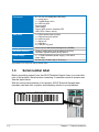
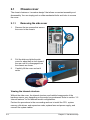
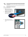
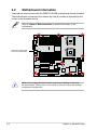
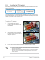
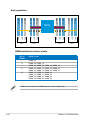
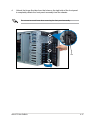
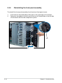
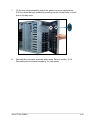
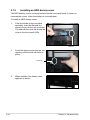
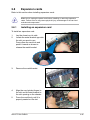
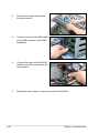
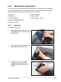
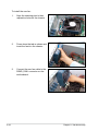
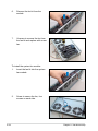
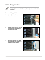
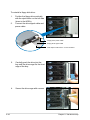
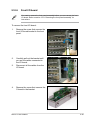
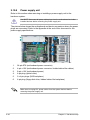
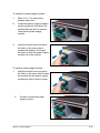
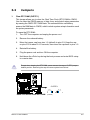
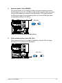
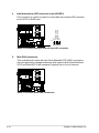
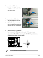
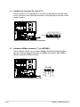
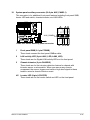
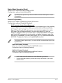
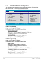
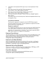
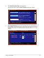
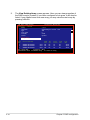
2.10.7 Roller wheels For convenient transport, install the roller wheels the came with the system package. Each wheel has a brake lock to stabilize the chassis in place. To install the chassis wheels: 1. Lay the chassis in its side. 2. Locate the designated screw holes for each of the four wheel sets. Take note of the numbers alongside each hole when placing screws. 3. Secure each wheel to the bottom of the chassis using four screws. 4. Repeat steps 2 and 3 to install the other three wheels. 3 1 2 4 Remove the chassis roller wheels if you wish to mount the system to a rack. To remove the chassis wheels: 1. Lay the system chassis on its side. 2. Use a Phillips screwdriver to remove the screws that secure the wheels to the bottom of the chassis. 3. Repeat step 2 to remove the other three roller wheels. ASUS TS700-E4/RX8 2-45 2.10.8 Power supply unit Refer to this section when removing or installing a power supply unit to the barebone system. You MUST disconnect all power cable plugs from the motherboard and other installed devices before removing the power supply unit. The picture below shows the motherboard and device connectors where the power plugs are connected. Refer to the Appendix at the end of this document for the power supply specifications. 4 1 2 3 5 6 5 1. 24-pin ATX (motherboard power connector) 2. 4-pin +12V (motherboard power connector, hidden behind the cables) 3. 8-pin +12V (motherboard power) 4. 4-pin plug (optical drive) 5. 2 x 4-pin plugs (SAS backplane) 6. 4-pin plug (floppy disk drive, hidden behind the backplane) Make sure to unplug ALL power cables from the system devices before removing the power supply unit. 2-46 Chapter 2: Hardware setup To uninstall a power supply module: 1. Refer to 2.1.1 to remove the chassis side cover. 2. Locate the power supply modules on the rear panel, and select the module that you want to remove. Unscrew the power supply module. 3. Hold the module lever and press the latch on the inner side to release the module. Firmly pull the lever to slide the power supply module out of the chassis. To install a power supply module: 1. 2. Hold the module lever and press the latch on the inner side to insert the module into the power supply module bay until it clicks in place. Screw to secure the power supply module. ASUS TS700-E4/RX8 2-47 2-48 Chapter 2: Hardware setup This chapter gives information about the motherboard that comes with the server. This chapter includes the motherboard layout, jumper settings, and connector locations. ASUS TS700-E4/RX8 Motherboard info Chapter 3 3- 3.1 Motherboard layout DSBF-D12/SAS model 33cm (13in) KBPWR1 PS/2 T: Mouse B: Keyboard ATX12V1 ATX12V2 DDR FB-DIMM_12 (64/72 bit, 240-pin module) USB1 USB2 COM1 CPU_FAN1 ATXPWR1 PSUSMB1 USBPW12 DDR FB-DIMM_11 (64/72 bit, 240-pin module) FBD_FAN1 DDR FB-DIMM_10 (64/72 bit, 240-pin module) REAR_FAN1 DDR FB-DIMM_01 (64/72 bit, 240-pin module) CPU1 DDR FB-DIMM_02 (64/72 bit, 240-pin module) FBD_FAN2 RJ-45 (LAN1) Intel® 5000P CPU2 DDR FB-DIMM_20 (64/72 bit, 240-pin module) RJ-45 (LAN2) DDR FB-DIMM_21 (64/72 bit, 240-pin module) FRNT_FAN4 ASMB3 DDR FB-DIMM_32 (64/72 bit, 240-pin module) FRNT_FAN2 CPU_FAN2 DDR FB-DIMM_30 (64/72 bit, 240-pin module) DDR FB-DIMM_31 (64/72 bit, 240-pin module) 82563EB FRNT_FAN1 DDR FB-DIMM_22 (64/72 bit, 240-pin module) 30.5cm (12in) ® REAR_FAN2 DSBF-D12/SAS VGA1 DDR FB-DIMM_00 (64/72 bit, 240-pin module) PCIE3 AMI 8Mb FWH DIP_SW1 Super I/O TPM1 CLRTC1 CR2032 3V Lithium Cell CMOS Power SAS_EN1 LAN_BW1 LPC1 PCIX4 LSI SAS1068 LPT1 COM2 SGPIO1 SAS2 SAS1 USBPW34 SB_PWR1 HDLED1 ® Intel 6321ESB BUZZER1 PCIX5 VGA_EN1 SATA3 SATA4 PCIE2 ATI ES1000 RECOVERY1 SATA5 SATA6 PCIE1 SATA1 SATA2 PRI_IDE1 LAN_EN1 BPSMB1 SASLED1 FLOPPY1 USB34 AUX_PANEL1 FRNT_FAN3 PANEL1 Onboard LED ® The motherboard comes with a standby power LED. The green LED lights up to indicate that the system is ON, in sleep mode, or in soft-off mode. This is a reminder that you should shut down the system and unplug the power cable before removing or plugging in any motherboard component. The illustration below shows the location of the onboard LED. SB_PWR1 DSBF-D12 Series Onboard LED ON OFF Standby Power Powered Off If the ATX12V2 connector is not connected, the REAR_FAN1/2, FRNT_FAN1/2/3/4, and FBD_FAN1/2 will not work and the system cannot power on. 3- Chapter 3: Motherboard info Layout contents Jumpers Page 1. Clear RTC RAM (CLRTC1) 3-5 2. LAN bandwidth setting (3-pin LAN_BW1) 3-6 3. USB device wake-up (3-pin USBPW12, USBPW34) 3-6 4. Keyboard power (3-pin KBPWR1) 3-7 5. VGA controller setting (3-pin VGA_EN1) 3-7 6. LAN controller setting (3-pin LAN_EN1) 3-8 8. Onboard storage setting (3-pin SAS_EN1) 3-8 9. Force BIOS recovery setting (3-pin RECOVERY1) 3-9 Switch Page 1. DIP switch (DIP_SW1) 3-10 Rear panel Page 1. PS/2 mouse port (green) 3-11 2. PS/2 keyboard port (purple) 3-11 3. USB 2.0 ports 1 and 2 (USB12_13) 3-11 4. Serial (COM1) port 3-11 5. Video Graphics Adapter port 3-11 6. LAN (RJ-45) ports 3-11 ASUS TS700-E4/RX8 3- 3- Internal connectors Page 1. Floppy disk drive connector (34-1 pin FLOPPY1) 3-12 2. IDE connector (40-1 pin PRI_IDE) 3-12 3. Serial ATA connectors (7-pin SATA1, SATA2, SATA3, SATA4, SATA5, SATA6 ) 3-13 4. Hard disk activity LED connector (4-pin HDLED1) 3-14 5. Mini-SAS connectors 3-14 6. USB connector (10-1 pin USB34) 3-15 7. Serial port connector (10-1 pin COM2) 3-16 8. CPU and system fan connectors (4-pin CPU_FAN1/2, REAR_FAN1/2, FRNT_FAN1/2/3/4, FBD_FAN1/2) 3-16 9. Power supply SMBus connector (5-pin PSUSMB1) 3-17 10. SSI power connectors (24-pin ATXPWR1, 8-pin ATX12V1, 4-pin ATX12V2) 3-17 11. Parallel port connector (26-1 pin LPT1) 3-18 12. Backplane SMBus connector (7-1 pin BPSMB1) 3-18 13. SAS LSI1068 ports LED connector (18-1 pin SASLED1) 3-19 14. Serial General Purpose Input/Output connector (6-1 pin SGPIO1) 3-19 15. System panel connector (20-1 pin PANEL1) 3-20 16. System panel auxiliary connector (20-2 pin AUX_PANEL1) 3-21 17. Trusted Platform Module connector (20-1 pin TPM1) 3-22 18. LPC connector for LPC debug card (14-1 pin LPC1) 3-22 Chapter 3: Motherboard info 3.2 1. Jumpers Clear RTC RAM (CLRTC1) This jumper allows you to clear the Real Time Clock (RTC) RAM in CMOS. You can clear the CMOS memory of date, time, and system setup parameters by erasing the CMOS RTC RAM data. The onboard button cell battery powers the RAM data in CMOS, which include system setup information such as system passwords. To erase the RTC RAM: 1. Turn OFF the computer and unplug the power cord. 2. Remove the onboard battery. 3. Move the jumper cap from pins 1-2 (default) to pins 2-3. Keep the cap on pins 2-3 for about 5~10 seconds, then move the cap back to pins 1-2. 4. Reinstall the battery. 5. Plug the power cord and turn ON the computer. 6. Hold down the <Del> key during the boot process and enter BIOS setup to re-enter data. ® Except when clearing the RTC RAM, never remove the cap on CLRTC jumper default position. Removing the cap will cause system boot failure! CLRTC1 1 2 DSBF-D12 Series Clear RTC RAM ASUS TS700-E4/RX8 Normal (Default) 2 3 Clear CMOS 3- LAN bandwidth setting (3-pin LAN_BW1) This jumper allows you to set the LAN bandwidth setting for more efficient IP load distribution. ® 2. LAN_BW1 1 2 2 3 Balanced mode (Default) Centric mode DSBF-D12 Series LAN bandwidth setting Balance Mode: It's x8 link between MCH and ESB2; LAN Centrical Mode: It's x4 link between MCH and ESB2. 3. USB device wake-up (3-pin USBPW12, USBPW34) Set these jumpers to +5V to wake up the computer from S1 sleep mode (CPU stopped, DRAM refreshed, system running in low power mode) using the connected USB devices. Set to +5VSB to wake up from S4 sleep mode (no power to CPU, DRAM in slow refresh, power supply in reduced power mode). USBPW12 2 3 ® 1 2 +5V (Default) +5VSB USBPW34 1 2 +5V (Default) 2 3 +5VSB DSBF-D12 Series USB device wake up 3- • The USB device wake-up feature requires a power supply that can provide 500mA on the +5VSB lead for each USB port; otherwise, the system will not power up. • If you are using Windows® 2000, you need to install Service Pack 4 to wake up the system from S4 sleep mode. • The total current consumed must NOT exceed the power supply capability (+5VSB) whether under normal condition or in sleep mode. Chapter 3: Motherboard info 4. Keyboard power (3-pin KBPWR1) This jumper allows you to enable or disable the keyboard wake-up feature. Set this jumper to pins 2-3 (+5VSB) to wake up the computer when you press a key on the keyboard (the default is the Space Bar). This feature requires an ATX power supply that can supply at least 1A on the +5VSB lead, and a corresponding setting in the BIOS. KBPWR1 2 3 ® 1 2 +5V (Default) +5VSB DSBF-D12 Series Keyboard power setting 5. VGA controller setting (3-pin VGA_EN1) ® These jumpers allow you to enable or disable the onboard VGA controller. Set to pins 1-2 to activate the VGA feature. VGA_EN1 1 2 DSBF-D12 Series VGA setting ASUS TS700-E4/RX8 Enable (Default) 2 3 Disable 3- LAN controller setting (3-pin LAN_EN1) This jumper allows you to enable or disable the onboard Intel® 6321 Gigabit LAN controller. Set to pins 1-2 to activate the Gigabit LAN feature. ® 6. LAN_EN1 1 2 Enable (Default) 2 3 Disable DSBF-D12 Series LAN1_EN setting Onboard storage setting (3-pin SAS_EN1) This jumper allows you to enable or disable the onboard LSI1068 SAS controller. ® 7. SAS_EN1 1 2 DSBF-D12 Series SAS setting 3- Enable (Default) 2 3 Disable Chapter 3: Motherboard info 8. Force BIOS recovery setting (3-pin RECOVERY1) This jumper allows you to quickly update or recover the BIOS settings when it becomes corrupted. To update the BIOS: 1. Prepare a floppy disk that contains the latest BIOS for the motherboard and the Phoenix Phlash16 utility. Make sure you download the correct BIOS for your motherboard model. 2. Set the jumper to pins 2-3. 3. Insert the floppy disk then turn on the system to update the BIOS. 4. Shut down the system. 5. Set the jumper back to pins 1-2. 6. Turn on the system. ® RECOVERY1 1 2 Normal (Default) 2 3 BIOS Recovery DSBF-D12 Series BIOS recovery setting Refer to section "4.1.3 ASUS Crashfree BIOS 2 utility" for more information. ASUS TS700-E4/RX8 3- 3.3 Switch This motherboard features a DIP switch for fan pin selection. DIP_SW1 ® ON(Default) ON 1 2 3 4 5 6 7 8 OFF DSBF-D12 Series DIP switches ON:4-PIN FAN OFF:3-PIN FAN SW1_CPU_FAN1 SW2_CPU_FAN2 SW3_FRNT_FAN1 SW4_FRNT_FAN2 SW5_FRNT_FAN3 SW6_FRNT_FAN4 SW7_REAR_FAN1 SW8_REAR_FAN2 The following table shows the corresponding switch for each fan connector. Switch 1 2 3 4 5 6 7 8 3-10 Fan connector CPU_FAN1 CPU_FAN1 FRNT_FAN1 FRNT_FAN2 FRNT_FAN3 FRNT_FAN4 REAR_FAN1 REAR_FAN2 • If you use a 4-pin fan but set the DIP switch for a 3-pin fan, the fan you installed may not work. • If you use a 3-pin fan but set the DIP switch for a 4-pin fan, the fan controll will not work and the fan you installed will always run at full speed. Chapter 3: Motherboard info 3.4 Connectors 3.4.1 Rear panel connectors 1 2 3 4 5 6 1. PS/2 mouse port (green). This port is for a PS/2 mouse. 2. PS/2 keyboard port (purple). This port is for a PS/2 keyboard. 3. USB 2.0 ports 1 and 2. These two 4-pin Universal Serial Bus (USB) ports are available for connecting USB 2.0 devices. 4. Serial (COM1) port. This 9-pin communication port is for pointing devices or other serial devices. 5. Video Graphics Adapter port. This port is for a VGA monitor or other VGAcompatible devices. 6. LAN (RJ-45) ports. These ports allow Gigabit connection to a Local Area Network (LAN) through a network hub. Refer to the table below for the LAN port LED indications. LAN port LED indications ACT/LINK LED SPEED LED Status Description Status Description OFF No link OFF 10 Mbps connection GREEN Linked ORANGE 100 Mbps connection BLINKING Data activity GREEN ASUS TS700-E4/RX8 1000 Mbps connection ACT/LINK LED SPEED LED LAN port 3-11 3.4.2 1. Internal connectors Floppy disk drive connector (34-1 pin FLOPPY1) This connector is for the provided floppy disk drive (FDD) signal cable. Insert one end of the cable to this connector, then connect the other end to the signal connector at the back of the floppy disk drive. ® Pin 5 on the connector is removed to prevent incorrect cable connection when using a FDD cable with a covered Pin 5. FLOPPY1 PIN 1 NOTE: Orient the red markings on the floppy ribbon cable to PIN 1. DSBF-D12 Series Floppy disk drive connector 2. 3-12 IDE connector (40-1 pin PRI_IDE1) This connector is for an Ultra DMA 100/66 signal cable. The Ultra DMA 100/66 signal cable has three connectors: a blue connector for the primary IDE connector on the motherboard, a black connector for an Ultra DMA 100/66 IDE slave device (optical drive/hard disk drive), and a gray connector for an Ultra DMA 100/66 IDE master device (hard disk drive). If you install two hard disk drives, you must configure the second drive as a slave device by setting its jumper accordingly. Refer to the hard disk documentation for the jumper settings. • Pin 20 on the IDE connector is removed to match the covered hole on the Ultra DMA cable connector. This prevents incorrect insertion when you connect the IDE cable. • Use the 80-conductor IDE cable for Ultra DMA 100/66 IDE devices. Chapter 3: Motherboard info ® PRI_IDE1 PIN 1 DSBF-D12 Series IDE connector 3. Serial ATA connectors (7-pin SATA1, SATA2, SATA3, SATA4, SATA5, SATA6 ) These connectors are for the Serial ATA signal cables for Serial ATA hard disk drives. SATA2 GND RSATA_TXP1 RSATA_TXN1 GND RSATA_RXN1 RSATA_RXP1 GND GND RSATA_TXP2 RSATA_TXN2 GND RSATA_RXN2 RSATA_RXP2 GND SATA3 SATA4 GND RSATA_TXP3 RSATA_TXN3 GND RSATA_RXN3 RSATA_RXP3 GND GND RSATA_TXP4 RSATA_TXN4 GND RSATA_RXN4 RSATA_RXP4 GND SATA5 SATA6 GND RSATA_TXP5 RSATA_TXN5 GND RSATA_RXN5 RSATA_RXP5 GND GND RSATA_TXP6 RSATA_TXN6 GND RSATA_RXN6 RSATA_RXP6 GND ® SATA1 DSBF-D12 Series SATA connectors ASUS TS700-E4/RX8 3-13 4. Hard disk activity LED connector (4-pin HDLED1) NC ADD_IN_CARDADD_IN_CARDNC ® This connector is used to connect to a hard disk drive active LED connector on the SCSI or RAID card. PIN1 HDLED1 DSBF-D12 Series storage card activity LED connector 5. Mini-SAS connectors ® This motherboard comes with two Serial Attached SCSI (SAS) connectors, the next-generation storage technology that supports both Serial Attached SCSI and Serial ATA. Each connector supports up to four (4) devices. DSBF-D12 Series MINI SAS connectors 3-14 Chapter 3: Motherboard info To connect the mini-SAS cable: Plug in the mini-SAS cable to the mini-SAS connector until the cable lock snaps in place. To disconnect the mini-SAS cable: 1. With your thumb, push down the cable lock to release. 2. While still keeping your thumb’s grip on the cable lock, carefully pull away the cable from the connector 6. USB connector (10-1 pin USB34) 1 2 Power USB PortB(-) USB PortB(+) GND NC ® This connector is for USB 2.0 ports. Connect the USB module cable to this connector, then install the module to a slot opening at the back of the system chassis. This USB connector complies with USB 2.0 specification that supports up to 480 Mbps connection speed. PIN1 DSBF-D12 Series USB connector Power USB PortA(-) USB PortA(+) GND USB34 The USB port module is purchased separately. ASUS TS700-E4/RX8 3-15 7. Serial port connector (10-1 pin COM2) ® This connector is for a serial (COM) port. Connect the serial port module cable to this connector, then install the module to a slot opening at the back of the system chassis. COM2 PIN1 DSBF-D12 Series Serial port connector The serial port module is purchased separately. 8. CPU and system fan connectors (4-pin CPU_FAN1/2, REAR_FAN1/2, FRNT_FAN1/2/3/4, FBD_FAN1/2) The fan connectors support cooling fans of 350 mA ~ 740 mA (8.88 W max.) or a total of 2.1 A ~ 4.44 A (53.28 W max.) at +12V. Connect the fan cables to the fan connectors on the motherboard, making sure that the black wire of each cable matches the ground pin of the connector. Do not forget to connect the fan cables to the fan connectors. Insufficient air flow inside the system may damage the motherboard components. These are not jumpers! Do not place jumper caps on the fan connectors! REAR_FAN1 REAR_FAN2 FRNT_FAN1 FRNT_FAN2 FRNT_FAN3 DSBF-D12 Series Fan connectors 3-16 GND FAN Power FAN Speed PWM Control FRNT_FAN3 GND FAN Power FAN Speed PWM Control GND FAN Power FAN Speed PWM Control FBD_FAN1 PWM Control FAN Speed FAN Power GND GND FAN Power FAN Speed PWM Control FBD_FAN2 GND FAN Power FAN Speed PWM Control CPU_FAN2 FRNT_FAN4 PWM Control FAN Speed FAN Power GND FBD_FAN2 CPU_FAN2 FRNT_FAN1 FRNT_FAN2 FRNT_FAN4 PWM Control FAN Speed FAN Power GND PWM Control FAN Speed FAN Power GND ® FBD_FAN1 REAR_FAN1 REAR_FAN2 CPU_FAN1 PWM Control FAN Speed FAN Power GND CPU_FAN1 Chapter 3: Motherboard info 9. Power supply SMBus connector (5-pin PSUSMB1) This connector is for the power supply SMB cable, if your power supply supports the SMBus function. ® I2C_7_CLK# I2C_7_DATA# NC GND +3.3V Remote Sense PSUSMB1 DSBF-D12 Series Power supply SMBus connector 10. SSI power connectors (24-pin ATXPWR1, 8-pin ATX12V1, 4-pin ATX12V2) These connectors are for SSI power supply plugs. The power supply plugs are designed to fit these connectors in only one orientation. Find the proper orientation and push down firmly until the connectors completely fit. • For a fully configured system, we recommend that you use an SSI 12 V-compliant power supply unit (PSU) for LGA771‑socket Intel® Xeon Dual Core processors (Bensley platform). • Do not forget to connect the 24+8+4-pin power plugs; otherwise, the system will not boot up. • Use of a PSU with a higher power output is recommended when configuring a system with more power consuming devices. The system may become unstable or may not boot up if the power is inadequate. • You must install a PSU with a higher power rating if you intend to install additional devices. ATXPWR1 ATX12V1 8-pin 12V1 12V1 12V2 12V2 +3 Volts -12 Volts Ground PSON# Ground Ground Ground -5 Volts +5 Volts +5 Volts +5 Volts Ground ® GND GND GND GND +3 Volts +3 Volts Ground +5 Volts Ground +5 Volts Ground Power OK +5V Standby +12 Volts +12 Volts +3 Volts 24-pin Power Connector +12V DC GND ATX12V2 DSBF-D12 Series ATX power connectors ASUS TS700-E4/RX8 4-pin +12V DC GND 3-17 11. Parallel port connector (26-1 pin LPT1) SLCT PE BUSY ACK# SPD7 SPD6 SPD5 SPD4 SPD3 SPD2 SPD1 SPD0 STB# ® This connector is for a parallel port. Connect the parallel port module cable to this connector, then install the module to a slot opening at the back of the system chassis. Pin 1 DSBF-D12 Series Parallel port connector GND GND GND GND GND GND GND GND SLIN# PINIT# ERROR# AFD# LPT1 12. Backplane SMBus connector (7-1 pin BPSMB1) ® This connector allows you to connect SMBus (System Management Bus) devices. Devices communicate with an SMBus host and/or other SMBus devices using the SMBus interface. BPSMB1 3-18 GND 12CDAT P2 +5V FAN_PWM DSBF-D12 Series BPSMB connector FAN_DC1 I2CCLK P2 PIN1 Chapter 3: Motherboard info 13. SAS LSI1068 ports LED connector (18-1 pin SASLED1) ACT_LED6 ACT_LED7 ACT_LED0 ACT_LED1 ACT_LED2 ACT_LED3 ACT_LED4 ACT_LED5 ® This connector is for the front panel LED port indicator that shows the SAS HDD status. PIN1 DSBF-D12 Series SASLED connector FLT_LED0 FLT_LED1 FLT_LED2 FLT_LED3 GND FLT_LED4 FLT_LED5 FLT_LED6 FLT_LED7 SASLED1 14. Serial General Purpose Input/Output connector (6-1 pin SGPIO1) ® This connector is used for the SGPIO peripherals for the LSI MegaRAID SATA LED. SGPIO1 ASUS TS700-E4/RX8 GND SATA_SLOAD SATA_SCLK DSBF-D12 Series SGPIO connector SDATAOUT0 SDATAOUT1 PIN1 3-19 15. System panel connector (20-1 pin PANEL1) This connector supports several chassis-mounted functions. POWERLED+ NC POWERLEDMLED+ MLEDNC +5V GND GND SPKROUT ® The system panel connector is color-coded for easy connection. • NMIBTN# GND POWERBTN# GND NC RESETBTN# GND DSBF-D12 Series System panel connector IDELED+ IDELED- PANEL1 System power LED (Green 3-pin PLED) This 3-pin connector is for the system power LED. Connect the chassis power LED cable to this connector. The system power LED lights up when you turn on the system power, and blinks when the system is in sleep mode. • Hard disk drive activity LED (Red 2-pin IDE_LED) This 2-pin connector is for the HDD Activity LED. Connect the HDD Activity LED cable to this connector. The IDE LED lights up or flashes when data is read from or written to the HDD. • System warning speaker (Orange 4-pin SPEAKER) This 4-pin connector is for the chassis-mounted system warning speaker. The speaker allows you to hear system beeps and warnings. • ATX power button/soft-off button (Yellow 2-pin PWRSW) This connector is for the system power button. Pressing the power button turns the system on or puts the system in sleep or soft-off mode depending on the BIOS settings. Pressing the power switch for more than four seconds while the system is ON turns the system OFF. • Reset button (Blue 2-pin RESET) This 2-pin connector is for the chassis-mounted reset button for system reboot without turning off the system power. 3-20 Chapter 3: Motherboard info 16. System panel auxiliary connector (20-2 pin AUX_PANEL1) This connector is for additional front panel features including front panel SMB, locator LED and switch, chassis intrusion, and LAN LEDs. 2 2 GND I2C_4_DATA# +5VSB LAN1_LINK LAN1_ACT LAN2_ACT LAN2_LINK NC I2C_4_CLK# ® 1 DSBF-D12 Series Auxiliary panel connector 1 +5VSB PIN1 CASEOPEN GND LOCATORLED1+ LOCATORLED1LOCATORBTN# GND LOCATORLED2LOCATORLED2+ AUX_PANEL1 3 4 5 4 Front panel SMB (6-1 pin FPSMB) These leads connect the front panel SMBus cable. 2 LAN activity LED (2-pin LAN1_LED, LAN2_LED) These leads are for Gigabit LAN activity LEDs on the front panel. 3 Chassis intrusion (2 pin CHASSIS) These leads are for the intrusion detection feature for chassis with intrusion sensor or microswitch. When you remove any chassis component, the sensor triggers and sends a high-level signal to these leads to record a chassis intrusion event. 4/5 Locator LED (6-pin LOCATOR) These leads are for the locator switch and LED on the front panel. ASUS TS700-E4/RX8 3-21 17. TPM connector (20-1 pin TPM) This connector supports a Trusted Platform Module (TPM) system, which can securely store keys, digital certificates, passwords, and data. A TPM system also helps enhance network security, protects digital identities, and ensures platform integrity. CK_33M_TPM LFRAMEn LRESETn LAD3 +3.3V LAD0 +3.3V X GND X ® TPM1 X GPIO2 GPIO LAD2 LAD1 GND X SERIRQ X X PIN1 DSBF-D12 Series TPM connector 18. LPC debug card connector.(14-1 pin LPC1) +3.3V GND LPC_LAD2 LPC_LAD0 PLTRST CLK ® This is a low pin count interface used to plug in the LPC debug card. PIN1 +3.3V +3.3V GND LPC_LAD3 LPC_LAD1 LFRAME_N GND LPC1 DSBF-D12 Series LPC debug card connector 3-22 Chapter 3: Motherboard info Chapter 4 BIOS setup This chapter tells how to change the system settings through the BIOS Setup menus. Detailed descriptions of the BIOS parameters are also provided. ASUS TS700-E4/RX8 4- 4.1 Managing and updating your BIOS The following utilities allow you to manage and update the motherboard Basic Input/Output System (BIOS) setup: 1. Phoenix Phlash16 BIOS Flash Utility (Updates the BIOS in DOS mode using a bootable floppy disk.) 2. ASUS CrashFree BIOS 2 (Recovers the BIOS using a bootable floppy disk when the BIOS file fails or gets corrupted.) 3. ASUS Update (Updates the BIOS in Windows® environment.) Refer to the corresponding sections for details on these utilities. 4.1.1 1. • ASUS Update is included in the support CD Rev. 2.0 and above. Download ASUS Update from the ASUS website (www.asus.com) if needed. • Save a copy of the original motherboard BIOS file to a bootable floppy disk in case you need to restore the BIOS in the future. Copy the original motherboard BIOS using the ASUS Update or Phoenix Phlash16 BIOS utilities. Refer to page 4-3 for details. Creating a bootable floppy disk Do the following to create a bootable floppy disk. DOS environment 4- a. Insert a 1.44MB floppy disk into the drive. b. At the DOS prompt, type format A:/S then press <Enter>. Chapter 4: BIOS setup 4.1.2 Updating the BIOS using the Phoenix Phlash16 Utility The Basic Input/Output System (BIOS) can be updated using the Phoenix Phlash16 Utility. Follow these instructions to update the BIOS using this utility. 1. Download the latest BIOS file from the ASUS web site. Rename the file to BIOS.WPH. Save the file to a floppy disk. Make sure you copy the correct BIOS file for the specific model of your motherboard. Save only the updated BIOS file in the floppy disk to avoid loading the wrong BIOS file. 2. Copy the Phoenix Phlash16 (phlash16.exe) utility from the Software folder of the support CD to the floppy disk with the latest BIOS file. 3. Boot the system in DOS mode using the bootable floppy disk you created earlier. 4. When the A:> appears, replace the bootable floppy disk with the floppy disk containing the new BIOS file and the Phoenix Phlash16 Utility. 5. At the prompt, type the following command string: phlash16 /mode=3BIOS.WPH. 6. The Phoenix Phlash16 Utility automatically updates the BIOS. Do not turn off or reset the system during the flashing process! 7. Restart the system after the utility completes the updating process. Make sure you remove the floppy disk from the drive When you execute the Phlash16.exe program and the screen displays "Cannot flash if Memory Managers" error message, refer to the Appendix to solve the problem. ASUS TS700-E4/RX8 4- 4.1.3 ASUS CrashFree BIOS 2 utility The ASUS CrashFree BIOS 2 is an auto recovery tool that allows you to restore the BIOS file when it fails or gets corrupted during the updating process. You can update a corrupted BIOS file using a floppy disk. Prepare a blank floppy disk before using this utility. Recovering the BIOS from a floppy disk A. Prepare the recovery diskette: 1. Insert the motherboard floppy disk to a PC, then boot from the support CD; the screen will show several optional items. 2. Select the item “Create the emergent BIOS Recovery diskette”. A) FreeDOS command prompt B) Create LSI 1068 SAS for Win2k/Win2k3 32 bit Driver Disk C) Create LSI 1068 SAS for Win2k3 64 bit Driver Disk D) Create LSI 1068 SAS for RHEL3 UP6 32 bit Driver Disk E) Create LSI 1068 SAS for RHEL3 UP6 64 bit Driver Disk F) Create LSI 1068 SAS for RHEL4 UP2 32 bit Driver Disk G) Create LSI 1068 SAS for RHEL4 UP2 64 bit Driver Disk H) Create the TS700-E4/RX8/RX8 emergent BIOS Recovery diskette I) Flash Phoenix BIOS for TS700-E4/RX8/RX8 system J) ESB2 ASF Firmware update K) Write TS700-E4/RX8/RX8 system FRU Please choose A TO K: B. To recover the BIOS from a floppy disk: 1. When BIOS corrupted, put this disk in the floppy disk drive, then turn on the machine to boot from the floppy disk. 2. The utility displays the following message and automatically checks the floppy for the recovery information. RN50 DDR1 A21 BIOS 3. When found, the utility reads the BIOS file and starts flashing the corrupted BIOS file. Before you recover the BIOS setting, refer to “2.6 Jumpers, Force BIOS recovery setting” for more information. 4- Chapter 4: BIOS setup Phoenix Phlash16 Utility Version 1.6.1.9 Copyright (c) Phoenix Technologies Ltd., 2005 Performing the following function Load Image File Verify interface information Backup system BIOS ROM Check flash memory type(s) Flash memory block: Save block Restore block Zero out block Erase block Program block Verify block Flash programming complete BIOS.WPH 30% Read in Identifying flash memory part type 00:00:00 (18) DO NOT shut down or reset the system while updating the BIOS! Doing so can cause system boot failure! 6. When the utility completes the updating process, a message appears, informing you that the flash memory has been programmed successfully. Phoenix Phlash16 Utility Version 1.6.1.9 Copyright (c) Phoenix Technologies Ltd., 2005 Phoenix Phlash16 Status Performing thesuccessfully following function Flash memory has been programmed Load Image File BIOS.WPH PRESS ANY KEY TO RESTART THE SYSTEM Verify interface information If the system does not restart Backup systemTURN BIOSTHE ROMPOWER OFF, THEN ON Check flash memory type(s) Flash memory block: Save block Restore block .......................... Zero out block .......................... Erase block √√√√√√√√√√√√√√√√√√√√√√√√√. Program block .√√√√√√√√√√√√√√√√√√√√√√√√√√ Verify block .√√√√√√√√√√√√√√√√√√√√√√√√√√ Flash programming complete Flash part: SST49LF008A DeviceID: Ready to restart the system ASUS TS700-E4/RX8 5a Mfr.ID: bf 00:00:00 (1E) 4- 7. Press the power button for more than four seconds to turn off the system. The recovered BIOS may not be the latest BIOS version for this motherboard. Visit the ASUS website (www.asus.com) to download the latest BIOS file. 4.1.4 ASUS Update utility The ASUS Update is a utility that allows you to manage, save, and update the motherboard BIOS in Windows® environment. The ASUS Update utility allows you to: • Save the current BIOS file • Download the latest BIOS file from the Internet • Update the BIOS from an updated BIOS file • Update the BIOS directly from the Internet, and • View the BIOS version information. This utility is available in the support CD that comes with the motherboard package. • ASUS Update is included in the support CD Rev. 2.0 and above. Download ASUS Update from the ASUS website (www.asus.com) if needed. • ASUS Update requires an Internet connection either through a network or an Internet Service Provider (ISP). Installing ASUS Update To install ASUS Update: 1. Place the support CD in the optical drive. The Drivers menu appears. 2. Click the Utilities tab, then click Install ASUS Update VX.XX.XX. 3. The ASUS Update utility is copied to your system. Quit all Windows® applications before you update the BIOS using this utility. 4- Chapter 4: BIOS setup Updating the BIOS through the Internet To update the BIOS through the Internet: 1. Launch the ASUS Update utility from the Windows® desktop by clicking Start > Programs > ASUS > ASUSUpdate > ASUSUpdate. The ASUS Update main window appears. 2. Select Update BIOS from the Internet option from the drop‑down menu, then click Next. ASUS TS700-E4/RX8 3. Select the ASUS FTP site nearest you to avoid network traffic, or click Auto. Select. Click Next. 4- 4. From the FTP site, select the BIOS version that you wish to download. Click Next. 5. Follow the screen instructions to complete the update process. The ASUS Update utility is capable of updating itself through the Internet. Always update the utility to avail all its features. Updating the BIOS through a BIOS file To update the BIOS through a BIOS file: 4- 1. Launch the ASUS Update utility from the Windows® desktop by clicking Start > Programs > ASUS > ASUSUpdate > ASUSUpdate. The ASUS Update main window appears. 2. Select Update BIOS from a file option from the drop‑down menu, then click Next. 3. Locate the BIOS file from the Open window, then click Save. 4. Follow the screen instructions to complete the update process. Chapter 4: BIOS setup 4.2 BIOS setup program This motherboard supports a programmable Low-Pin Count (LPC) chip that you can update using the provided utility described in section “4.1 Managing and updating your BIOS.” Use the BIOS Setup program when you are installing a motherboard, reconfiguring your system, or prompted to “Run Setup.” This section explains how to configure your system using this utility. Even if you are not prompted to use the Setup program, you can change the configuration of your computer in the future. For example, you can enable the security password feature or change the power management settings. This requires you to reconfigure your system using the BIOS Setup program so that the computer can recognize these changes and record them in the CMOS RAM of the LPC chip. The LPC chip on the motherboard stores the Setup utility. When you start up the computer, the system provides you with the opportunity to run this program. Press <Del> during the Power-On Self-Test (POST) to enter the Setup utility; otherwise, POST continues with its test routines. If you wish to enter Setup after POST, restart the system by pressing <Ctrl+Alt+Delete>, or by pressing the reset button on the system chassis. You can also restart by turning the system off and then back on. Do this last option only if the first two failed. The Setup program is designed to make it as easy to use as possible. Being a menu-driven program, it lets you scroll through the various sub-menus and make your selections from the available options using the navigation keys. • The default BIOS settings for this motherboard apply for most conditions to ensure optimum performance. If the system becomes unstable after changing any BIOS settings, load the default settings to ensure system compatibility and stability. Select the Load Default Settings item under the Exit Menu. See section “4.8 Exit Menu.” • The BIOS setup screens shown in this section are for reference purposes only, and may not exactly match what you see on your screen. • Visit the ASUS website (www.asus.com) to download the latest BIOS file for this motherboard. ASUS TS700-E4/RX8 4- 4.2.1 BIOS menu screen Menu items Main Menu bar Advanced Server General help Configuration fields PhoenixBIOS Setup Utility Security Boot Exit System Date System Time [09/08/2006] [15 : 30 : 36] Floppy A [1.44/1.25 MB 31/2”] IDE Configuration IDE Channel 0 Master IDE Channel 0 Slave SATA Port 1 SATA Port 2 SATA Port 3 SATA Port 4 [None] [None] [None] [None] [None] [None] Item Specific Help <Tab>, <Shift+Tab>, or <Enter> selects field. System Information F1:Help ESC: Exit ↑↓ :Select Item →← :Select Menu -/+: Change Value Enter: Select SubMenu F5: Setup Defaults F10: Save and Exit Sub-menu items 4.2.2 Legend bar Menu bar The menu bar on top of the screen has the following main items: Main For changing the basic system configuration Advanced For changing the advanced system settings Server For changing the advanced server settings Security For changing the security settings Boot For changing the system boot configuration Exit For selecting the exit options and loading default settings To select an item on the menu bar, press the right or left arrow key on the keyboard until the desired item is highlighted. 4-10 Chapter 4: BIOS setup 4.2.3 Legend bar At the bottom of the Setup screen is a legend bar. The keys in the legend bar allow you to navigate through the various setup menus. The following table lists the keys found in the legend bar with their corresponding functions. Navigation key Function <F1> Displays the General Help screen <F9> Loads setup default values <Esc> Exits the BIOS setup or returns to the main menu from a sub‑menu Left or Right arrow Selects the menu item to the left or right Up or Down arrow Moves the highlight up or down between fields Page Down or – (minus) Scrolls backward through the values for the highlighted field Page Up or + (plus) Scrolls forward through the values for the highlighted field <Enter> Brings up a selection menu for the highlighted field <F10> Saves changes and exit 4.2.4 Menu items The highlighted item on the menu bar displays the specific items for that menu. For example, selecting Main shows the Main menu items. The other items (Advanced, Power, Boot, and Exit) on the menu bar have their respective menu items. 4.2.5 Sub-menu items A solid triangle before each item on any menu screen means that the iteam has a sub-menu. To display the sub-menu, select the item and press <Enter>. 4.2.6 Configuration fields These fields show the values for the menu items. If an item is user‑configurable, you can change the value of the field opposite the item. You cannot select an item that is not user-configurable. A configurable field is enclosed in brackets, and is highlighted when selected. To change the value of a field, select it then press <Enter> to display a list of options. Refer to “4.2.7 Pop-up window.” ASUS TS700-E4/RX8 4-11 4.2.7 Pop-up window Select a menu item then press <Enter> to display a pop-up window with the configuration options for that item. Main Advanced Server PhoenixBIOS Setup Utility Security Boot Exit System Date System Time [09/08/2006] [15 : 30 : 36] Floppy A [1.44/1.25 MB 31/2”] IDE Configuration IDE Channel 0 Master IDE Channel 0 Slave SATA Port 1 SATA Port 2 SATA Port 3 SATA Port 4 System Information F1:Help ESC: Exit [None] [None] Disabled [None] 360 Kb [None] 1.2 MB [None] [None] 720 Kb 1.44/1.25 MB 2.88 MB ↑↓ :Select Item →← :Select Menu Item Specific Help 5 5 3 3 3 <Tab>, <Shift+Tab>, or <Enter> selects field. 1/4” 1/4” 1/2” 1/2” 1/2” -/+: Change Value Enter: Select SubMenu F5: Setup Defaults F10: Save and Exit Pop-up menu 4.2.8 General help At the top right corner of the menu screen is a brief description of the selected item. 4-12 Chapter 4: BIOS setup 4.3 Main menu When you enter the BIOS Setup program, the Main menu screen appears, giving you an overview of the basic system information. Refer to section “4.2.1 BIOS menu screen” for information on the menu screen items and how to navigate through them. Main Advanced Server PhoenixBIOS Setup Utility Security Boot Exit System Date System Time [09/08/2006] [15 : 30 : 36] Floppy A [1.44/1.25 MB 3½”] IDE Configuration IDE Channel 0 Master IDE Channel 0 Slave SATA Port 1 SATA Port 2 SATA Port 3 SATA Port 4 [None] [None] [None] [None] [None] [None] Item Specific Help <Tab>, <Shift+Tab>, or <Enter> selects field. System Information F1:Help ESC: Exit 4.3.1 ↑↓ :Select Item →← :Select Menu -/+: Change Value Enter: Select SubMenu F5: Setup Defaults F10: Save and Exit System Date [Day xx/xx/xxxx] Allows you to set the system date. 4.3.2 System Time [xx:xx:xx] Allows you to set the system time. 4.3.3 Floppy A [1.44M, 3½in.] Sets the type of floppy drive installed. Configuration options: [Disabled] [360 Kb 5¼”] [1.2 MB 5¼”] [720 Kb 3 ½” ] [1.44/1.25 MB 3 ½”] [2.88 MB 3½”] ASUS TS700-E4/RX8 4-13 4.3.4 IDE Configuration PhoenixBIOS Setup Utility Main IDE Configuration Fixed disk boot sector: Item Specific Help [Normal] S-ATA Configuration F1:Help ESC: Exit ↑↓ :Select Item →← :Select Menu -/+: Change Value Enter: Select SubMenu Write protects boot sector on hard disk to protect against viruses. F5: Setup Defaults F10: Save and Exit Fixed disk boot sector [Normal] Setting this item to [Write Protect] prevents write access to the boot sector on the hard disk to protect against viruses. The default setting [Normal] allows write access. Configuration options: [Normal] [Write Protect] S-ATA Configuration For the storage of this system is controlled by LSI1068 PCI-X SAS controller, the following items are unavailable. Keep the configuratons as default. PhoenixBIOS Setup Utility Main S-ATA Configuration Item Specific Help Parallel ATA [Enabled] Serial ATA: [Enabled] SATA Controller Mode Option: [Enhanced] SATA RAID Enable [Disabled] SATA AHCI Enable [Disabled] F1:Help ESC: Exit ↑↓ :Select Item →← :Select Menu -/+: Change Value Enter: Select SubMenu Enable the PATA F5: Setup Defaults F10: Save and Exit Parallel ATA [Enabled] Allows you to enable or disable the parallel ATA function. Configuration options: [Disabled] [Enabled] 4-14 Chapter 4: BIOS setup Native Mode Operation [Auto] Allows you to choose the native mode for ATA. Configuration options: [Auto] [Serial ATA] The above item appears only when the SATA Controller Mode Option is set to [Compatible] Serial ATA [Enabled] Allows you to enable or disable the Serial ATA function. Configuration options: [Disabled] [Enabled] SATA Controller Mode Option [Enhanced] Allows selection of the Serial ATA operation mode depending on the operating system (OS) that you installed. When you set this item to Enhanced Mode, Serial ATA and Parallel ATA devices are auto‑detected and placed in native IDE mode. Set to Enhanced Mode if you are using native OS, such as Windows® 2000/XP. When you set this item to Compatible Mode, Serial ATA and Parallel ATA devices are auto‑detected and placed in legacy mode. Set this item to [Compatible] if you are using legacy OS, e.g. Windows ME/98/NT, MS-DOS. Configuration options: [Compatible] [Enhanced] The following items appear only if you set the SATA Controller Mode Option item to [Enhanced]. SATA RAID Enable [Disabled] Allows you to enable or disable the Serial ATA RAID function. Configuration options: [Disabled] [Enabled] SATA AHCI Enable [Disabled] Allows you to enable or disable the Serial ATA AHCI function. Configuration options: [Disabled] [Enabled] • AHCI mode item will support only under Windows environment. • Due to the driver limitation, you will not find any SATA driver if you install Fedora core 4. ASUS TS700-E4/RX8 4-15 4.3.5 IDE Channel 0 Master/Slave PhoenixBIOS Setup Utility Main IDE Channel 0 Master Type: [Auto] Multi-Sector Transfers LBA Mode Control 32-Bit I/O Transfer Mode Ultra DMA Mode F1:Help ESC: Exit ↑↓ :Select Item →← :Select Menu Item Specific Help [None] [Disabled] [Disabled] [Disabled] [Standard] [Disabled] -/+: Change Value Enter: Select SubMenu Auto = Autotyping None = Disabling drive ATAPI Removable = ATAPI media (e.g., LS120, USB Floppy, USB Zip) CD-ROM = CD-ROM drive IDE Removable = IDE removable media (e.g., IDE Zip drive) Other ATAPI = Other ATAPI media User = You supply the hard disk drive type F5: Setup Defaults F10: Save and Exit Type [Auto] Selects the type of IDE drive. Setting to Auto allows automatic selection of the appropriate IDE device type. Select [CD-ROM] if you are specifically configuring a CD-ROM drive. Select [ATAPI Removable] if your device is either a ZIP, or LS-120 drive. Select [User] to manually enter the parameters of the device. Configuration options: [Auto] [User] [Other ATAPI] [IDE Removable] [CD‑ROM] [ATAPI Removable] [None] • Except for 32-Bit I/O item, the following items become user-configurable when the Type item is not set to [Auto]. • Suggest you to keep the default setting of this item [Auto]. • For items that have no sub-menu, you have to use -/+ to change the values. Multi-Sector Transfers [Disabled] Enables or disables data multi-sectors transfers. When set to 2~16 Sectors, the data transfer from and to the device occurs multiple sectors at a time if the device supports multi-sector transfer feature. When set to [Disabled], the data transfer from and to the device occurs one sector at a time. Configuration options: [Disabled] [2 Sectors] [4 Sectors] [8 Sectors] [16 Sectors] LBA Mode Control [Disabled] Enables or disables the LBA mode. Setting to Enabled enables the LBA mode if the device supports this mode, and if the device was not previously formatted with LBA mode disabled. Configuration options: [Disabled] [Enabled] 32-Bit I/O [Disabled] Enables or disables 32-bit data transfer. Configuration options: [Disabled] [Enabled] 4-16 Chapter 4: BIOS setup Transfer Mode [Stadard] Allows you to select the mothod for the data transferring if the hard disk supports this feature. Configuration options: [Standard] [Fast PIO 1] [Fast PIO 2] [Fast PIO 3] [Fast PIO 4] [FPIO 3 / DMA 1] [FPIO 4 / DMA2] Ultra DMA Mode [Disabled] When this item is set to [Mode 0-5], the UDMA capability allows improved transfer speeds and data integrity for supported IDE devices. Configuration options: [Disabled] [Mode 0] [Mode 1] [Mode 2] [Mode 3] [Mode 4] [Mode 5] 4.3.6 SATA Port 1/2/3/4 PhoenixBIOS Setup Utility Main SATA Port 1 [None] Type: [Auto] Multi-Sector Transfers LBA Mode Control 32-Bit I/O Transfer Mode Ultra DMA Mode [Disabled] [Disabled] [Disabled] [Standard] [Disabled] F1:Help ESC: Exit ↑↓ :Select Item →← :Select Menu -/+: Change Value Enter: Select SubMenu Item Specific Help Auto = Autotyping None = Disabling drive ATAPI Removable = ATAPI media (e.g., LS120, USB Floppy, USB Zip) CD-ROM = CD-ROM drive IDE Removable = IDE removable media (e.g., IDE Zip drive) Other ATAPI = Other ATAPI media User = You supply the hard disk drive type F5: Setup Defaults F10: Save and Exit Type [Auto] Selects the type of IDE drive. Setting to Auto allows automatic selection of the appropriate IDE device type. Select [CD-ROM] if you are specifically configuring a CD-ROM drive. Select [ATAPI Removable] if your device is either a ZIP, LS-120, or MO drive. Select [User] to manually enter the parameters of the device. Configuration options: [Auto] [User] [Other ATAPI] [IDE Removable] [CD‑ROM] [ATAPI Removable] • Except for 32-Bit I/O item, the following items become user-configurable when the Type item is not set to [Auto]. • For items that have no sub-menu, you have to use -/+ to change the values. ASUS TS700-E4/RX8 4-17 Multi-Sector Transfers [Disabled] Enables or disables data multi-sectors transfers. When set to 2~16 Sectors, the data transfer from and to the device occurs multiple sectors at a time if the device supports multi-sector transfer feature. When set to [Disabled], the data transfer from and to the device occurs one sector at a time. Configuration options: [Disabled] [2 Sectors] [4 Sectors] [8 Sectors] [16 Sectors] LBA Mode Control [Disabled] Enables or disables the LBA mode. Setting to Enabled enables the LBA mode if the device supports this mode, and if the device was not previously formatted with LBA mode disabled. Configuration options: [Disabled] [Enabled] 32-Bit I/O [Disabled] Enables or disables 32-bit data transfer. Configuration options: [Disabled] [Enabled] Transfer Mode [Stadard] Allows you to select the mothod for the data transferring if the hard disk supports this feature. Configuration options: [Standard] [Fast PIO 1] [Fast PIO 2] [Fast PIO 3] [Fast PIO 4] [FPIO 3 / DMA 1] [FPIO 4 / DMA2] Ultra DMA Mode [Disabled] When this item is set to [Mode 0-5], the UDMA capability allows improved transfer speeds and data integrity for supported IDE devices. Configuration options: [Disabled] [Mode 0] [Mode 1] [Mode 2] [Mode 3] [Mode 4] [Mode 5] 4-18 Chapter 4: BIOS setup 4.3.7 System Information This menu gives you an overview of the general system specifications. The BIOS automatically detects the items in this menu. PhoenixBIOS Setup Utility Main System Information Model Name Model ID ASUS-BIOS Version Date Item Specific Help DSBF-D12/SAS 8041A0 The detailed information for CPUs 1000.007 09/06/2006 Processor Information System Memory Information F1:Help ESC: Exit ↑↓ :Select Item →← :Select Menu -/+: Change Value Enter: Select SubMenu F5: Setup Defaults F10: Save and Exit The items in this menu are non-user configurable. Model Name/Model ID Displays the ASUS internal model information. ASUS BIOS Displays the BIOS revision and build date. ASUS TS700-E4/RX8 4-19 Processor Information Displays the auto-detected CPU specification. Main PhoenixBIOS Setup Utility Processor Information *** CPU1 : Brand Intel(R) Xeon(TM) CPU 2.83GHz Speed 2.800GHz Ratio Actual 7 Max 7 Cache L1/32 KB L2/4096 KB ID/uCode 0F64h/02h F1:Help ESC: Exit ↑↓ :Select Item →← :Select Menu -/+: Change Value Enter: Select SubMenu Item Specific Help All items on this menu cannot be modified in user mode. If any items require changes, please consult your system Supervisor. F5: Setup Defaults F10: Save and Exit System Memory Information Displays the auto-detected system memory information. Main System Memory Information Speed : DDR2 533 Total Memory: 1024MB DIMM_00-- 1024MB, AMB Temperature: 57 DIMM_01-- None DIMM_02-- None DIMM_10-- None DIMM_11-- None DIMM_12-- None DIMM_20-- None DIMM_21-- None DIMM_22-- None DIMM_30-- None DIMM_31-- None DIMM_32-- None F1:Help ESC: Exit 4-20 PhoenixBIOS Setup Utility ↑↓ :Select Item →← :Select Menu -/+: Change Value Enter: Select SubMenu Item Specific Help All items on this menu cannot be modified in user mode. If any items require changes, please consult your system Supervisor. F5: Setup Defaults F10: Save and Exit Chapter 4: BIOS setup 4.4 Advanced menu The Advanced menu items allow you to change the settings for the CPU and other system devices. Take caution when changing the settings of the Advanced menu items. Incorrect field values can cause the system to malfunction. Main Advanced Server PhoenixBIOS Setup Utility Security Boot Exit WARNING:Setting wrong value in below sections may cause system to malfunction. Advanced Processor Options Chipset Configuration PCI Configuration ICH USB Control Sub-Menu Peripheral Devices Configuration ACPI Configuration Power On Configuration Hardware Monitor F1:Help ESC: Exit 4.4.1 ↑↓ :Select Item →← :Select Menu -/+: Change Value Enter: Select SubMenu Item Specific Help Options for CPU F5: Setup Defaults F10: Save and Exit Advanced Processor Options The following screen appears when you install an Intel® 5000 series CPU. Advanced PhoenixBIOS Setup Utility Advanced Processor Options Multiprocessor Specification Frequency Ratio Hyperthreading: [1.4] [Default] [Enabled] Intel(R) Virtualization Technology Machine Checking [Enabled] [Enabled] Fast String operations Compatible FPU Code Split Lock operations C1 Enhanced Mode No Execute Mode Mem Protection Adjacent Cache Line Prefetch Set Max Ext CPUID = 3 [Enabled] [Disabled] [Enabled] [Enabled] [Enabled] [Enabled] [Disabled] F1:Help ESC: Exit ↑↓ :Select Item →← :Select Menu ASUS TS700-E4/RX8 Item Specific Help -/+: Change Value Enter: Select SubMenu Configures the MP Specification revision level. Some operating systems will require 1.1 for compatibility reasons. F5: Setup Defaults F10: Save and Exit 4-21 Multiprocessor Specification [1.4] Allows you to configure the MP Specification revision level. Configuration options: [1.1] [1.4] Frequency Ratio [Default] Allows you to select the processor frequency ratio. Configuration options: [Default] [X 12] Hyperthreading [Enabled] Allows you to enable or disable the Intel® Hyper-Threading Technology feature. Configuration options: [Disabled] [Enabled] Intel(R) Virtualization Technology [Enabled] Configuration options: [Disabled] [Enabled] *Machine Checking [Enabled] Configuration options: [Disabled] [Enabled] *Fast String Operations [Enabled] Configuration options: [Disabled] [Enabled] *Compatible FPU Code [Disabled] Configuration options: [Disabled] [Enabled] *Split Lock operations [Enabled] Configuration options: [Disabled] [Enabled] C1 Enhanced Mode [Enabled] Allows you to enable or disable C1E mode. In C1E mode, the CPU power consumption is lower when idle. Configuration options: [Disabled] [Enabled] No Execute Mode Mem Protection [Enabled] Configuration options: [Disabled] [Enabled] Set Max Ext CPUID = 3 [Disabled] Enable this item to boot legacy operating systems that cannot support CPUs with extended CPUID functions. Configuration options: [Disabled] [Enabled] Adjacent Cache Line Prefetch [Enabled] Configuration options: [Disabled] [Enabled] Items with * mark are for technical personnel to debug only. 4-22 Chapter 4: BIOS setup Echo TPR [Disabled] Configuration options: [Disabled] [Enabled] Scroll down to display the following items, which appear in both Intel® 5000, 5100, and 5300 series CPU. Item Specific Help Advanced Processor Options Discrete MTRR Allocation Intel EIST support: F1:Help ESC: Exit [Disabled] [Disabled] ↑↓ :Select Item →← :Select Menu -/+: Change Value Enter: Select SubMenu F5: Setup Defaults F10: Save and Exit Discrete MTRR Allocation [Disabled] Configuration options: [Disabled] [Enabled] Intel EIST support [Disabled] Enables or disables EIST support. When enabled, this item allows the CPU P state to dynamically change based on system loading. Configuration options: [Disabled] [Enabled] The following screen appears when you install an Intel® 5100 and 5300 series CPU. Refer to page 21 for the description of items that are in common with Intel® 5000 series CPU screen. Advanced PhoenixBIOS Setup Utility Advanced Processor Options Multiprocessor Specification Numbers of Stop Grant [1.4] [Per Core] Intel(R) Virtualization Technology Machine Checking [Enabled] [Enabled] Fast String Operations Compatible FPU Code Split Lock operations Thermal Management 2 C1 Enhanced Mode No Execute Mode Mem Protection Adjacent Cache Line Prefetch Set Max Ext CPUID = 3 Echo TPR [Enabled] [Disabled] [Enabled] [Enabled] [Enabled] [Enabled] [Enabled] [Disabled] [Disabled] F1:Help ESC: Exit ↑↓ :Select Item →← :Select Menu -/+: Change Value Enter: Select SubMenu Item Specific Help Configures the MP Specification revision level. Some operating systems will require 1.1 for compatibility reasons. F5: Setup Defaults F10: Save and Exit Numbers of Stop Grant [Per Core] Configuration options: [Per Core] [Single] Thermal Management 2 [Enabled] Configuration options: [Disabled] [Enabled] ASUS TS700-E4/RX8 4-23 4.4.2 Chipset Configuration This menu shows the chipset configuration settings. Select an item then press <Enter> to display a pop-up menu with the configuration options. PhoenixBIOS Setup Utility Advanced Chipset Configuration Crystal Beach Configure Enable SERR Signal Condition Demand Scrub Enable Patrol Scrub Enable [Enabled] [Single Bit] [Enabled] [Enabled] 4GB PCI Hole Granularity Memory Branch Mode Branch 0 Rank Interleave Branch 0 Rank Sparing Branch 1 Rank Interleave Branch 1 Rank Sparing Enhanced x8 Detection Force ITK Config Clocking [256 MB] [Interleave] [4:1] [Disabled] [4:1] [Disabled] [Enabled] [Disabled] F1:Help ESC: Exit ↑↓ :Select Item →← :Select Menu -/+: Change Value Enter: Select SubMenu F5: Setup Defaults F10: Save and Exit Scroll down to display the following items: Item Specific Help Advanced Processor Options FBDIMM(s) Thermal Throttling Open Loop Type F1:Help ESC: Exit ↑↓ :Select Item →← :Select Menu [Open Loop] [Best Performan] -/+: Change Value Enter: Select SubMenu F5: Setup Defaults F10: Save and Exit Crystal Beach Configure Enable [Enabled] Allows you to enable or disable the Configuration/Memory mapped accesses to the Crystal Beach Configuration space located in Device 8, Fn 0, and Fn 1. Configuration options: [Disabled] [Enabled] 4-24 Chapter 4: BIOS setup SERR Signal Condition [Single Bit] Allows you to select the ECC error that the SERR# asserts. Configuration options: [None] [Single Bit] [Multiple Bit] [Both] Demand Scrub Enable [Enabled] Enables or disables the Demand Scrubbing. Configuration options: [Disabled] [Enabled] Patrol Scrub Enable [Enabled] Enables or disables the Patrol Scrubbing. Configuration options: [Disabled] [Enabled] 4GB PCI Hole Granularity [256 MB] Allows you to select the granularity of the PCI hole for PCI resource. Configuration options: [256 MB] [512 MB] [1.0 GB] [2.0 GB] Memory Branch Mode [Interleave] Allows you to select the memory branch mode. Configuration options: [Sequential] [Interleave] [Mirror] [Single channel 0] Branch 0 Rank Interleave [4:1] Allows you to select the Branch 0 Rank Interleave. Configuration options: [1:1] [2:1] [4:1] Branch 0 Rank Sparing [Disabled] Allows you to enable or disable the Branch 0 rank/DIMM Sparing feature. Configuration options: [Disabled] [Enabled] Branch 1 Rank Interleave [4:1] Allows you to select the Branch 1 Rank Interleave. Configuration options: [1:1] [2:1] [4:1] Branch 1 Rank Sparing [Disabled] Allows you to enable or disable the Branch 1 rank/DIMM Sparing feature. Configuration options: [Disabled] [Enabled] Enhanced x8 Detection [Enabled] Allows you to enable or disable the enhanced x8 DRAM UC error detection. Configuration options: [Disabled] [Enabled] ASUS TS700-E4/RX8 4-25 Force ITK Config Clocking [Disabled] Allows you to enable or disable the FBD configuration for ITK test suite. Configuration options: [Disabled] [Enabled] FBDIMM(s) Thermal Throttling [Open Loop] Allows you to disable or set the thermal throttling control. Configuration options: [Open Loop] [Closed Loop] [ASUS MemCool Fan] [Disabled] Set this item to [ASUS MemCool Fan] for a better fan management. Open Loop Type [Best Performance] Allows you to select the Open Loop Type. Configuration options: [Best Performance] [Best Acoustic] [User Define] The following items appear when you set the Open Loop Type to [User Define]. Environment Temperature [25 ºC] Allows you to select the Environment Temperature value. Configuration options: [20 ºC] ~ [40 ºC] Temperature Rise [25 ºC] Allows you to select the Temperature Rise value. Configuration options: [10 ºC] ~ [30 ºC] FBDIMM(s) Air Flow [2.0] Allows yout to select the Air Flow value. Configuration options: [1.0] [1.5] ~ [5.0] 4-26 Chapter 4: BIOS setup 4.4.3 PCI Configuration This menu shows the PCI configuration settings. Select an item then press <Enter> to display the configuration options. PhoenixBIOS Setup Utility Advanced PCI Configuration Reset Configuration Data Plug & Play OS Palette Snooping PCI PCI PCI PCI PCI PCI Device, Device, Device, Device, Device, Device, F1:Help ESC: Exit Slot Slot Slot Slot Slot Slot Item Specific Help [No] [No] [Disabled] #1 #2 #3 #4 #5 #6 ↑↓ :Select Item →← :Select Menu -/+: Change Value Enter: Select SubMenu Select ‘Yes’ if you want to clear the Extended System Configuration Data (ESCD) area. F5: Setup Defaults F10: Save and Exit Reset Configuration Data [No] This item allows you to clear the Extended System Configuration Data (ESCD) area. Configuration options: [No] [Yes] Plug & Play O/S [No] When set to [No], BIOS configures all the devices in the system. When set to [Yes] and if you install a Plug and Play operating system, the operating system configures the Plug and Play devices not required for boot. Configuration options: [No] [Yes] Palette Snooping [Disabled] When set to [Enabled], the palette snooping feature informs the PCI devices that an ISA graphics device is installed in the system so that the latter can function correctly. Configuration options: [Disabled] [Enabled] ASUS TS700-E4/RX8 4-27 PCI Device, Slot #1 ~ 6 Allows you to configure the specific PCI devices. PhoenixBIOS Setup Utility Advanced PCI Device, Slot #1 Option ROM Scan: F1:Help ESC: Exit Item Specific Help [Enabled] ↑↓ :Select Item →← :Select Menu Initialize device expansion ROM -/+: Change Value Enter: Select SubMenu F5: Setup Defaults F10: Save and Exit Option ROM Scan [Enabled] Allows you to enable or disable the device expansion ROM. Configuration options: [Enabled] [Disabled] 4-28 Chapter 4: BIOS setup 4.4.4 ICH USB Control Sub-Menu The items in this menu allow you to display the USB configuration settings. Select an item then press <Enter> to display the configuration options. Advanced PhoenixBIOS Setup Utility ICH USB Control Sub-Menu USB Function [Enabled] USB 2.0 Controller Legacy USB Support: [Enabled] [Enabled] F1:Help ESC: Exit ↑↓ :Select Item →← :Select Menu -/+: Change Value Enter: Select SubMenu Item Specific Help Enable USB host controller. F5: Setup Defaults F10: Save and Exit USB Function [Enabled] Allows you to enable the USB host controller. Configuration options: [Disabled] [Enabled] The following items appear only if you enable the USB Function item. USB 2.0 Controller [Enabled] Allows you to enable or disable the USB 2.0 controller. Setting this item to [Enabled] allows the built-in high speed USB support in the BIOS to turn on automatically when you install high speed USB devices. Configuration options: [Disabled] [Enabled] Legacy USB Support [Enabled] Allows you to enable or disable support for USB devices on legacy operating systems (OS). Setting to [Enabled] allows the system to detect the presence of USB devices at startup. If detected, the USB controller legacy mode is enabled. if no USB device is detected, the legacy USB support is disabled. Configuration options: [Disabled] [Enabled] ASUS TS700-E4/RX8 4-29 4.4.5 Peripheral Devices Configuration This menu shows the peripheral devices configuration settings. Select an item then press <Enter> to display the configuration options. Advanced PhoenixBIOS Setup Utility Peripheral Devices Configuration COM1 Port: Base I/O address: Interrupt: COM2 Port: Mode: Base I/O address: Interrupt: Parallel port: Base I/O address: Interrupt: Mode: DMA channel Floppy disk controller F1:Help ESC: Exit ↑↓ :Select Item →← :Select Menu [Enabled] [3F8] [IRQ 4] [Enabled] [Normal] [2F8] [IRQ 3] [Enabled] [378] [IRQ 7] [ECP] [DMA 3] [Enabled] -/+: Change Value Enter: Select SubMenu Item Specific Help Confugure serial port A using options: [Disabled] No configuration [Enabled] User configuration [Auto] BIOS or OS chooses configuration (OS Controlled) Displayed when controlled bt OS F5: Setup Defaults F10: Save and Exit COM1 Port [Enabled] Allows you to configure COM1 port. Configuration options: [Disabled] [Enabled] [Auto] Base I/O address [3F8] Allows you to select the base I/O address for COM1 port. Configuration options: [3F8] [2F8] [3E8] [2E8] Interrupt [IRQ 4] Allows you to set the interrupt for COM1 port Configuration options: [IRQ 3] [IRQ 4] COM2 Port [Enabled] Allows you to configure COM2 port. Configuration options: [Disabled] [Enabled] [Auto] Mode [Normal] Allows you to set the mode for COM2 port. Configuration options: [Normal] [IR] [ASK-IR] Base I/O address [2F8] Allows you to select the base I/O address for COM2 port. Configuration options: [3F8] [2F8] [3E8] [2E8] Interrupt [IRQ 3] Allows you to set the interrupt for COM2 port. Configuration options: [IRQ 3] [IRQ 4] 4-30 Chapter 4: BIOS setup Parallel port [Enabled] Allows you to configure the parallel port. Configuration options: [Disabled] [Enabled] [Auto] Base I/O address [378] Allows you to select the base I/O address for the parallel port. Configuration options: [378] [278] [3BC] Interrupt [IRQ 7] Allows you to set the interrupt for the parallel port. Configuration options: [IRQ 5] [IRQ 7] Mode [ECP] Allows you to set the mode for the parallel port. Configuration options: [Output only] [Bi-directional] [EPP] [ECP] DMA channel [DMA 3] Allows you to set the DMA channel for the parallel port. Configuration options: [DMA 1] [DMA 3] Floppy disk controller [Enabled] Allows you to configure the floppy disk controller. Configuration options: [Disabled] [Enabled] [Auto] ASUS TS700-E4/RX8 4-31 4.4.6 ACPI Configuration This menu shows the Advanced Configuration and Power Interface (ACPI) configuration settings. Select an item then press <Enter> to display the configuration options. PhoenixBIOS Setup Utility Advanced ACPI Configuration ACPI Version Features Headless Mode ACPI EMS Support F1:Help ESC: Exit Item Specific Help [ACPI v1.0] [Disabled] [Disabled] ↑↓ :Select Item →← :Select Menu -/+: Change Value Enter: Select SubMenu Enable RSDP pointers to 64-bit Fixed System Description Tables. F5: Setup Defaults F10: Save and Exit ACPI Version Features [ACPI v1.0] Allows you to enable RSDP pointers to 64-bit fixed system description tables. Configuration options: [ACPI v1.0] [ACPI v2.0] [ACPI v3.0] Headless Mode [Disabled] Allows you to enable or disable the headless operation mode through ACPI. Configuration options: [Disabled] [Enabled] ACPI EMS Support [Disabled] Allows you to enable or disable the ACPI EMS support. Configuration options: [Disabled] [Enabled] 4-32 Chapter 4: BIOS setup 4.4.7 Power On Configuration This menu shows the power configuration settings. Select an item then press <Enter> to display the configuration options. PhoenixBIOS Setup Utility Advanced Power On Configuration Restore on AC Power Loss [Last State] Power On Power On Power On Power-On [Disabled] [Disabled] [Disabled] [Disabled] F1:Help ESC: Exit By By By By PS/2 Keyboard PS/2 Mouse PME# RTC Alarm ↑↓ :Select Item →← :Select Menu -/+: Change Value Enter: Select SubMenu Item Specific Help Configures the system state after recovering from power failure. F5: Setup Defaults F10: Save and Exit Restore on AC Power Loss [Last State] When set to [Power Off], the system goes into “off state” after an AC power interruption. When set to [Power On], the system turns on automatically after a power interruption. When set to [Last State], the system goes into whatever was the system state (on or off) before the power interruption. Configuration options: [Power Off] [Power On] [Last State] Power Up By PS/2 Keyboard [Disabled] Allows you to use specific keys on the PS/2 keyboard to turn on the system. This feature requires an ATX power supply that provides at least 1A on the +5VSB lead. Configuration options: [Enabled] [Disabled] Power Up By PS/2 Mouse [Disabled] When set to [Enabled], this parameter allows you to use the PS/2 mouse to turn on the system. This feature requires an ATX power supply that provides at least 1A on the +5VSB lead. Configuration options: [Enabled] [Disabled] Power On By PME# [Disabled] Allows you to enable or disable the PME and onboard LAN to generate a wake-up event. Configuration options: [Disabled] [Enabled] Power On By RTC Alarm [Disabled] Allows you to enable or disable RTC to generate a wake-up event. Configuration options: [Disabled] [Enabled] ASUS TS700-E4/RX8 4-33 The following items appear only if you enable the Power On By RTC Alarm item. RTC Alarm Date [0] To set the date of alarm, highlight this item and press <Enter> to display a date chart. Press <+> or <-> to change scroll through the options, then press <Enter> when done. The default setting [0] is equivalent to everyday alarm. Configuration options: [0] [1] ~ [31] RTC Alarm Date [00 : 00 : 00] To set the time of alarm: 1. Press <+> or <-> to set the desired value. 2. Press <Tab> to move to the next field. 3. Press <Enter> when done. 4.4.8 Hardware Monitor This menu shows the hardware monitor configuration settings. Select an item then press <Enter> to display the configuration options. The following screens appear when you install Intel® 5000 series CPU. Hardware Monitor CPU1 Domain 0 Temperature CPU1 Domain 1 Temperature CPU2 Domain 0 Temperature CPU2 Domain 1 Temperature SYSTEM1 Temperature SYSTEM2 Temperature CPU_FAN1 Speed CPU_FAN2 Speed FRN_FAN1 Speed FRN_FAN2 Speed FRN_FAN3 Speed FRN_FAN4 Speed REAR_FAN1 Speed REAR_FAN2 Speed Smart Fan Control F1:Help ESC: Exit 4-34 PhoenixBIOS Setup Utility Advanced ↑↓ :Select Item →← :Select Menu 39oC/102oF 29oC/84oF 0oC/32oF 0oC/32oF 39oC/102oF 29oC/84oF 2925 RPM N/A N/A N/A N/A N/A N/A N/A [Smart Fan II] -/+: Change Value Enter: Select SubMenu Item Specific Help To select the fan speed control model. F5: Setup Defaults F10: Save and Exit Chapter 4: BIOS setup Scroll down to display more items: Advanced PhoenixBIOS Setup Utility Hardware Monitor Item Specific Help CPU1 Domain 0 Target Temperature CPU1 Domain 1 Target Temperature CPU2 Domain 0 Target Temperature CPU2 Domain 1 Target Temperature SYSTEM1 Target Temperature SYSTEM2 Target Temperature [72ºC] [72ºC] [72ºC] [72ºC] [60ºC] [60ºC] FBD_FAN1 Speed VCORE0 Voltage VCORE1 Voltage VTT +1.5V +1.8V +3V +12V +5V +5VSB VBAT N/A 1.25 V 1.25 V 1.21 V 1.56 V 1.79 V 3.28 V 11.91 V 4.87 V 4.96 V 3.10 V F1:Help ESC: Exit ↑↓ :Select Item →← :Select Menu -/+: Change Value Enter: Select SubMenu Full fan speed will be started when the temperature reaches the selected target value. F5: Setup Defaults F10: Save and Exit CPU1/2 Domain 0/1 Temperature, SYSTEM1/2 Temperature, CPU_FAN1/2 Speed, FRN_FAN1/2/3/4 Speed, REAR_FAN1/2 Speed These fields show the auto-detected values and are not user-configurable. If no fan is installed, the field shows 0 RPM. Smart Fan Control [Smart Fan II] Allows you to disable or configure the Smart Fan feature. Configuration options: [Disabled] [Smart Fan] [Smart Fan II] CPU1/2 Domain 0/1 Target Temperature (CPU1/2 Target Temperature) Allows you to set the target CPU temperature at which the CPU fan will run at full speed. Configuration options: [44ºC] ~ [66ºC] SYSTEM1/2 Target Temperature Allows you to set the target sytem temperature at which the system fan will start running if the fan is not yet turned on. Configuration options: [39ºC] ~ [60ºC] FBD_FAN1/2 Speed, VCORE0/1 Voltage, VTT, +1.5V, +1.8V, +3V, +12V, +5V, +5VSB, VBAT These fields show the auto-detected values and are not user-configurable. ASUS TS700-E4/RX8 4-35 The following screens appear when you install Intel® 5100 and 5300 series CPU. PhoenixBIOS Setup Utility Advanced Hardware Monitor 39oC/102oF 29oC/84oF 39oC/102oF 29oC/84oF 2925 RPM N/A N/A N/A N/A N/A N/A N/A [Smart Fan II] [00 ºC] [00 ºC] CPU1 Temperature CPU2 Temperature SYSTEM1 Temperature SYSTEM2 Temperature CPU_FAN1 Speed CPU_FAN2 Speed FRN_FAN1 Speed FRN_FAN2 Speed FRN_FAN3 Speed FRN_FAN4 Speed REAR_FAN1 Speed REAR_FAN2 Speed Smart Fan Control CPU1 Target Temperature CPU2 Target Temperature F1:Help ESC: Exit ↑↓ :Select Item →← :Select Menu -/+: Change Value Enter: Select SubMenu Item Specific Help To select the fan speed control model. F5: Setup Defaults F10: Save and Exit Scroll down to display more items: PhoenixBIOS Setup Utility Advanced Hardware Monitor SYSTEM1 Target Temperature SYSTEM2 Target Temperature [050] [050] FBD_FAN1 Speed FBD_FAN2 Speed VCORE0 Voltage VCORE1 Voltage VTT +1.5V +1.8V +3V +12V +5V +5VSB VBAT N/A N/A 1.25 V 1.25 V 1.21 V 1.56 V 1.79 V 3.28 V 11.91 V 4.87 V 4.96 V 3.10 V F1:Help ESC: Exit ↑↓ :Select Item →← :Select Menu -/+: Change Value Enter: Select SubMenu Item Specific Help Full fan speed will be started when the temperature reaches the selected target value. F5: Setup Defaults F10: Save and Exit CPU1/2 Temperature, SYSTEM1/2 Temperature, CPU_FAN1/2 Speed, FRN_FAN1/2/3/4 Speed, REAR_FAN1/2 Speed These fields show the auto-detected values and are not user-configurable. If no fan is installed, the field shows 0 RPM. Smart Fan Control [Smart Fan II] Allows you to disable or configure the Smart Fan feature. Configuration options: [Disabled] [Smart Fan] [Smart Fan II] CPU1/2 Target Temperature Allows you to set the target CPU temperature at which the CPU fan will run at full speed. Configuration options: [44ºC] ~ [66ºC] 4-36 Chapter 4: BIOS setup SYSTEM1/2 Target Temperature Allows you to set the target sytem temperature at which the system fan will start running if the fan is not yet turned on. Configuration options: [39ºC] ~ [60ºC] FBD_FAN1/2 Speed, VCORE0/1 Voltage, VTT, +1.5V, +1.8V, +3V, +12V, +5V, +5VSB, VBAT These fields show the auto-detected values and are not user-configurable. 4.5 Server menu This Server menu items allow you to customize the server features. Main Advanced Server PhoenixBIOS Setup Utility Security Boot Exit Console Redirection DMI Event Logging F1:Help ESC: Exit 5.5.1 Main Item Specific Help Additional setup menus to configure console. ↑↓ :Select Item →← :Select Menu -/+: Change Value Enter: Select SubMenu F5: Setup Defaults F10: Save and Exit Console Redirection Advanced Server Console Redirection Com Port Address F1:Help ESC: Exit PhoenixBIOS Setup Utility Security Boot Exit ↑↓ :Select Item →← :Select Menu ASUS TS700-E4/RX8 Item Specific Help [Disabled] -/+: Change Value Enter: Select SubMenu If enabled, it will use a port on the motherboard. F5: Setup Defaults F10: Save and Exit 4-37 Com Port Address [Disabled] Allows you to disable or select the COM port to use. Configuration options: [Disabled] [Onboard COM1 port] [Onboard COM2 port] The following items appear only if you set the Com Port Address item to [Onboard COM1 port] or [Onboard COM2 port]. Baud Rate [115.2K] Allows you to enable the specified baud rate. Configuration options: [300] [1200] [2400] [9600] [19.2K] [38.4K] [57.6K] [115.2K] Console Type [PC-ANSI, 7bit] Allows you to enable the specified console type. Configuration options: [VT100] [VT100, 8bit] [PC-ANSI, 7bit] [PC ANSI] [VT100+] [VT-UTF8] [ASCII] Flow Control [CTS/RTS] Allows you to select the flow control for console redirection. Configuration options: [None] [XON/XOFF] [CTS/RTS] Console connection [Direct] Allows you to select the console connection. [Direct] indicates that the console is connected directed to the system. [Via modem] indicates that a modem is used to connect. Configuration options: [Direct] [Via modem] Continue C.R. after POST [Off] Set this item to [On] if you want console redirection to continue after the operating system has loaded. Configuration options: [Off] [On] # of video pages to support [1] Allows you to set the number of video pages to allocate for console redirection when the video hardware is not available. Press <-> or <+> to set the value, or enter the value using the numeric keypad. Configuration options: [1] ~ [8] 4-38 Chapter 4: BIOS setup 4.5.2 Main DMI Event Logging Advanced Server PhoenixBIOS Setup Utility Security Boot Exit DMI Event Logging Event log validity Event log capacity Valid Space Available View DMI event log [Enter] Event Logging ECC Event Logging [Enabled] [Enabled] Mark DMI events as read Clear all DMI event logs [Enter] [No] F1:Help ESC: Exit ↑↓ :Select Item →← :Select Menu -/+: Change Value Enter: Select SubMenu Item Specific Help View the contents of the DMI event log. F5: Setup Defaults F10: Save and Exit Event log validity, Event log capacity Displays the auto-detected system information. View DMI event log [Enter] Press <Enter> to view the contents of the DMI event log. Event Logging [Enabled] Enables or disables to allows logging of DMI events. Configuration options: [Disabled] [Enabled] ECC Event Logging [Enabled] Enables or disables to allows logging of ECC events. Configuration options: [Disabled] [Enabled] Mark DMI events as read [Enter] Press <Enter> to mark all DMI events in the event log as read. Clear all DMI event logs [No] Allows you to keep or clear the DMI event log after rebooting. Configuration options: [No] [Yes] ASUS TS700-E4/RX8 4-39 4.6 Main F1 ESC Security menu Advanced Server PhoenixBIOS Setup Utility Security Boot Exit Supervisor Password Is: User Password Is: Clear Clear Set Supervisor Password Set User Password Password Check Password Lock Mode Removable Device Boot Flash Write [Enter] [Enter] [Setup] [Disabled] [Enabled] [Enabled] Help Exit ↑↓ →← Select Item Select Menu -/+ Enter Item Specific Help Change Values Select Sub-Menu Supervisor Password controls access to the setup utility. F9 F10 Setup Defaults Save and Exit Supervisor Password Is [Clear] User Password Is [Clear] These fields allow you to set passwords: To set a password: 1. Select an item then press <Enter>. 2. Type in a password using a combination of a maximum of eight (8) alphanumeric characters, then press <Enter>. 3. When prompted, confirm the password by typing the exact characters again, then press <Enter>. The password field setting is changed to Set. To clear the password: 1. Select the item Set Supervisor Password or Set User Password, depending on which password you want to clear. Press <Enter>. The following message appears: Main Advanced PhoenixBIOS Setup Utility Security Boot Exit Supervisor Password Is: User Password Is: Clear Clear Set Supervisor Password [Enter] Set User Password [Enter] Password Check [Setup] Set Supervisor Password Lock Mode [Disabled] Password Removable Device Boot [Enabled] Enter Current Password [ ] Flash Write [Enabled] Enter New Password [ ] Confirm New Password [ ] F1:Help ESC: Exit 4-40 Server ↑↓ :Select Item →← :Select Menu -/+: Change Value Enter: Select SubMenu Item Specific Help Supervisor Password controls access to the setup utility. F5: Setup Defaults F10: Save and Exit Chapter 4: BIOS setup 2. In the Enter current password field, type in your current password. Press <Enter>. 3. The cursor moves to the next field, Enter new password. Press <Enter>. Do not type anything in this field. 4. The cursor moves to the next field, Confirm new password. Press <Enter>. Do not type anything in this field. 5. When the confirmation message “Password has been changed” appears, press <Enter>. The display returns to the Security menu. Note that the password field on top is changed to Clear. A note about passwords The Supervisor password is required to enter the BIOS Setup program preventing unauthorized access. The User password is required to boot the system preventing unauthorized use. Forgot your password? If you forget your password, you can clear it by erasing the CMOS Real Time Clock (RTC) RAM. The RAM data containing the password information is powered by the onboard button cell battery. If you need to erase the CMOS RAM, refer to section “2.6 Jumpers” for instructions. Password Check [Setup] This field requires you to enter the password before entering the BIOS setup or the system. Select [Setup] to require the password before entering the BIOS Setup. Select [System] to require the password before entering the system. Configuration options: [Setup] [Always] Password Lock Mode [Enabled] When set to [Enabled], the keyboard is locked and the user has no privilege to launch the BIOS setup utility when installing adapter cards during option ROM initialization. Configuration options: [Disabled] [Enabled] Removable Device Boot [Enabled] Allows you to enable or disable booting from a legacy floppy, USB floppy, or IDE optical drive. Configuration options: [Disabled] [Enabled] Flash Write [Enabled] Set this item to [Disabled] to write-protect the BIOS flash memory. Configuration options: [Disabled] [Enabled] ASUS TS700-E4/RX8 4-41 4.7 Main Boot menu Advanced Server PhoenixBIOS Setup Utility Security Boot Exit Boot Device Priority Item Specific Help Boot Features F1:Help ESC: Exit 4.7.1 Main ↑↓ :Select Item →← :Select Menu Specify the boot priority sequence of all boot devices. -/+: Change Value Enter: Select SubMenu F5: Setup Defaults F10: Save and Exit Boot Device Priority Advanced Server PhoenixBIOS Setup Utility Security Boot Exit Boot Device Priority Item Specific Help Boot priority order: 1: Legacy Floppy Drives 2: IDE 1: 3: IDE 2: 4: 5: 6: 7: 8: Keys used to view or configure devices: Up and Down arrows select a device. <+> and <-> moves the device up or down. <f> and <r> specifies the device as fixed or removable. <x> excludes or includes the device to boot. <Shift + 1> enables or disables the device. <1 - 4> Loads default boot sequence. Excluded from boot order: : PCI BEV: IBA GE Slot 0400 v1236 : PCI BEV: IBA GE Slot 0400 v1236 F1:Help ESC: Exit ↑↓ :Select Item →← :Select Menu -/+: Change Value Enter: Select SubMenu F5: Setup Defaults F10: Save and Exit Refer to the following table for keys assigned to configure devices. Key/s 4-42 Use this key to... <Up arrow> / <Down arrow> select a device. <+> / <-> move the device up or down. <f> / <r> specify the device as fixed or removable. <x> exclude or include the device to boot. <Shift + 1> enable or disable the device. <1 - 4> load default boot sequence. Chapter 4: BIOS setup 4.7.2 Main Boot Features Advanced Server PhoenixBIOS Setup Utility Security Boot Exit Boot Features Quick Boot Full Logo Display Bootup Num-Lock PS/2 Mouse Summary screen: POST Errors SETUP prompt Interrupt 19 Capture [Enabled] [Enabled] [On] [Auto Detect] [Enabled] [Enabled] [Enabled] [Enabled] Item Specific Help Allows the BIOS to skip certain tests while booting. This will decrease the time needed to boot the system. F1 Help ↑↓ Select Item -/+ Change Values F9 Setup F1:Help ↑↓ :Select Item -/+: Change Value F5: SetupDefaults Defaults ESC Exit →← Select Menu Enter Select Save andand Exit ESC: Exit →← :Select Menu Enter: SelectSub-Menu SubMenu F10F10: Save Exit Quick Boot [Enabled] Enabling this item allows the BIOS to skip some power on self tests (POST) while booting to decrease the time needed to boot the system. When set to [Disabled], BIOS performs all the POST items. Configuration options: [Disabled] [Enabled] Full Logo Display [Enabled] Allows you to enable or disable the full screen logo display feature. Configuration options: [Disabled] [Enabled] Bootup Num-Lock [On] Allows you to select the power-on state for the NumLock. Configuration options: [Auto] [On] [Off] PS/2 Mouse [Auto Detect] Allows you to enable or disable support for PS/2 mouse. Configuration options: [Disabled] [Enabled] [Auto Detect] Summary screen: [Enabled] When this item is enabled, the system configuration is displayed during POST. Configuration options: [Disabled] [Enabled] POST Errors [Enabled] When set to Enabled, the system waits for the F1 key to be pressed when error occurs. Configuration options: [Disabled] [Enabled] ASUS TS700-E4/RX8 4-43 SETUP prompt [Enabled] When this item is set to Enabled, the system displays the message “Press DEL to run Setup” during POST. Configuration options: [Disabled] [Enabled] Interrupt 19 Capture [Enabled] When set to [Enabled], this function allows the option ROMs to trap Interrupt 19. Configuration options: [Disabled] [Enabled] 4.8 Main Exit menu Advanced Server PhoenixBIOS Setup Utility Security Boot Exit Save Changes and Exit Discard Changes and Exit Discard Changes Load Setup Defaults F1:Help ESC: Exit ↑↓ :Select Item →← :Select Menu Item Specific Help Save any changes to CMOS, exit BIOS Setup then reboot system. -/+: Change Value Enter: Select SubMenu F5: Setup Defaults F10: Save and Exit Save Changes and Exit Select this option then press <Enter>, or simply press <F10>, to save your changes to CMOS before exiting the Setup utility. When a confirmation window appears: • select [Yes], then press <Enter> to save and exit. • select [No], then press <Enter>, or simply press <Esc>, to cancel the command and return to the Exit menu. Discard Changes and Exit Select this option then press <Enter> if you wish to exit the Setup utility without saving your changes. When a confirmation window appears: 4-44 • select [Yes], then press <Enter> to discard your changes and exit. • select [No], then press <Enter>, or simply press <Esc>, to cancel the command and return to the Exit menu. Chapter 4: BIOS setup Discard Changes Select this option to discard the changes that you made, and restore the previously saved values. When a confirmation window appears: • select [Yes], then press <Enter> to discard any changes and load the previously saved values. • select [No], then press <Enter>, or simply press <Esc>, to cancel the command and return to the Exit menu. Load Setup Defaults Select this option then press <Enter>, or simply press <F9>, to load the optimized values for each of the Setup menu items. When a confirmation window appears: • select [Yes], then press <Enter> to load the default values. • select [No], then press <Enter>, or simply press <Esc>, to cancel the command and return to the Exit menu. ASUS TS700-E4/RX8 4-45 4-46 Chapter 4: BIOS setup This chapter provides instructions for setting up, creating, and configuring RAID sets using the available utilities. ASUS TS700-E4/RX8 RAID configuration Chapter 5 5- 5.1 Setting up RAID The motherboard comes with the following RAID solutions: • LSI1068 PCI-X SAS controller supports SAS disk drives and RAID0, RAID1, and RAID1E configuration. 5.1.1 RAID definitions RAID 0 (Data striping) optimizes two identical hard disk drives to read and write data in parallel, interleaved stacks. Two hard disks perform the same work as a single drive but at a sustained data transfer rate, double that of a single disk alone, thus improving data access and storage. Use of two new identical hard disk drives is required for this setup. RAID 1 (Data mirroring) copies and maintains an identical image of data from one drive to a second drive. If one drive fails, the disk array management software directs all applications to the surviving drive as it contains a complete copy of the data in the other drive. This RAID configuration provides data protection and increases fault tolerance to the entire system. Use two new drives or use an existing drive and a new drive for this setup. The new drive must be of the same size or larger than the existing drive. RAID 1-E (Enhanced RAID 1) has a striped layout with each stripe unit having a secondary (or alternate) copy stored on a different disk. You can use three or more hard disk drives for this configuration. RAID 0+1 is data striping and data mirroring combined without parity (redundancy data) having to be calculated and written. With the RAID 0+1 configuration you get all the benefits of both RAID 0 and RAID 1 configurations. Use four new hard disk drives or use an existing drive and three new drives for this setup. RAID 5 stripes both data and parity information across three or more hard disk drives. Among the advantages of RAID 5 configuration include better HDD performance, fault tolerance, and higher storage capacity. The RAID 5 configuration is best suited for transaction processing, relational database applications, enterprise resource planning, and other business systems. Use a minimum of three identical hard disk drives for this setup. 5- • If you want to boot the system from a hard disk drive included in a created RAID set, copy first the RAID driver from the support CD to a floppy disk before you install an operating system to the selected hard disk drive. • If you need to create a RAID 5 set, you have to install an optional ZCR card. Contact ASUS retailers for more information. Chapter 5: RAID configuration 5.1.2 Installing hard disk drives The motherboard supports Serial ATA for RAID set configuration. For optimal performance, install identical drives of the same model and capacity when creating a disk array. To install the SATA hard disks for RAID configuration: 1. Install the SATA hard disks into the drive bays following the instructions in the system user guide. 2. Connect a SATA signal cable to the signal connector at the back of each drive and to the SATA connector on the motherboard. 3. Connect a SATA power cable to the power connector on each drive. 5.1.3 Setting the RAID item in BIOS You must set the RAID item in the BIOS Setup before you can create a RAID set from SATA hard disk drives attached to the SATA connectors supported by the Intel ® 6321ESB Southbridge chip. To do this: 1. Enter the BIOS Setup during POST. 2. Go to the Main Menu > IDE Configuration > S-ATA Configuration, then press <Enter>. 3. Set the SATA Controller Mode Option item to [Enhanced], then press <Enter>. 4. Set the SATA RAID Enable item to [Enabled]. 5. Save your changes, then exit the BIOS Setup. Refer to Chapter 4 for details on entering and navigating through the BIOS Setup. 5.1.4 RAID configuration utilities You may use the LSI1068 SAS Configuration Utility if you installed SAS hard disk drives to the mini-SAS connector(s) supported by the LSI1068 PCI-X SAS controller. Refer to the succeeding sections for details on how to use each RAID configuration utility. ASUS TS700-E4/RX8 5- 5.2 LSI Logic MPT Setup Utility The LSI Logic MPT Setup Utility is an integrated RAID solution that allows you to allows you to create the following RAID set(s) from SAS hard disk drives supported by the LSI1068 PCI-X SAS controller: • RAID 1 (Integrated Mirroring) • RAID 1E (Integrated Mirroring Enhanced) • RAID 0 (Integrated Striping) 5.2.1 Integrated Mirroring Overview The Integrated Mirroring (IM) feature supports simultaneous mirrored volumes with two disks (IM). Integrated Mirroring Enhanced (IME) supports three to eight disks, or seven mirrored disks plus a hot spare disk. The IM feature supports hot swap capability, so when a disk in an IM volume failes, you can easily restore the volume, and the swapped disk is automatically remirrored. Creating Integrated Mirroring volumes • You may use disks of different sized in IM and IME volumes; however, the size of the smallest disk determines the “logical” size of each member disk. • Do not combine Serial ATA and SAS disks in one volume. • The RAID BIOS setup screens shown in this section are for reference only and may not exactly match the items on your screen. To create an IM volume: 1. Turn on the system after installing all SAS hard disk drives. 2. During POST, press <Ctrl+C> to enter the SAS configuration utility. LSI Logic Corp. MPT SAS BIOS MPTBIOS-6.08.05.00 (2006.08.02) Copyright 2000-2006 LSI Logic Corp. Adapter(s) disabled by user Press Ctrl-C to start LSI Logic Configuration Utility... 5- Chapter 5: RAID configuration 3. The following screen appears. Select a channel and press <Enter> to enter the setup. LSI Logic Config Utility v6.08.05.00 (2006.08.02) Adapter List Global Properties Adapter PCI PCI PCI PCI FW Revision Status BUS Dev Fnc Slot SAS1068 05 03 00 00 1.15.00.00-IR Disabled Esc = Exit Menu F1/Shift+1 = Help Allt+N = Global Properties -/+ = Alter Boot Order Boot Order 0 Ins/Del = Alter Boot List The numbers of the channel depend on the controller. 4. The Adapter Properties screen appears. Use the arrow keys to select RAID Properties, then press <Enter>. LSI Logic Config Utility v6.08.05.00 (2006.08.02) Adapter Properties -- SAS1068 Adapter SAS1068 PCI Slot 00 PCI Address(Bus/Dev/Func) 05.03.00 MPT Firmware Revision 1.15.00.00.IR SAS Address 500E0180:60831008 NVIDIA Version 25.02 Status Disabled Boot Order 0 (Enabled OS only) Boot Support RAID Properties SAS Topology Advanced Adapter Properties Esc = Exit Menu F1/Shift+1 = Help Enter = Select Item -/+ = Change Item 5. The Select New Array Type screen apprears. Use the arrow keys to select Create IM Volume, then press <Enter>. LSI Logic Config Utility v6.08.05.00 (2006.08.02) Select New Array Type -- SAS1068 Create IM Volume Create Integrated Mirror Array of 2 disks plus an optional hot spare. Data on the primary disk may be migrated. Create IME Volume Create Integrated Mirrored Enhanced Array of 3 to 8 disks including an optional hot spare. ALL DATA on array disks will be DELETED! Create IS Volume Create Integrated Striping array of 2 to 8 disks. ALL DATA on array disks will be DELETED! Esc = Exit Menu F1/Shift+1 = Help Enter = Choose array type to create ASUS TS700-E4/RX8 5- 6. The Create New Array screen shows the disks you can add to make up the IM volume. Use the arrow key to select a disk, then move the cursor to the RAID Disk column. To include this disk in the array, press <+>, <->, or <Space>. You may also specify the Hot Spare disk here. Select the disk, then move the cursor to the Hot Spr column, then press <+>, <->, or <Space>. LSI Logic Config Utility v6.08.05.00 (2006.08.02) Create New Array -- SAS1068 Array Type: IM Array Size(MB): -----Slot Device Identifier RAID Hot Drive Pred Size Num Disk Spr Status Fail (MB) 0003 [NO] [NO] ------- ---70007 0 SEAGATE ST373454SS 70007 1 SEAGATE ST373454SS 0003 [NO] [NO] ------- ---35003 2 SEAGATE ST373454SS 0003 [NO] [NO] ------- ---35003 3 SEAGATE ST373454SS 0003 [NO] [NO] ------- ---- Esc = Exit Menu F1/Shift+1 = Help SPACE/+/- = Select disk for array or hot spare C = Create array By default, the RAID Disk field shows No before array creation. This field is grayed out under the following conditions: 5- • The disk does not meet the minimum requirements for use in a RAID array. • The disk is not large enough to mirror existing data on the primary drive. • The disk has been selected as the Hot Spare for the RAID array. • The disk is already part of another array. Chapter 5: RAID configuration 7. A confirmation screen appears. Press <M> to keep existing data on the first disk. If you choose this option, data on the first disk will be mirrored on the second disk that you will add to the volume later. Make sure the data you want to mirror is on the first disk. Press <D> to overwrite any data and create the new IM array. LSI Logic Config Utility v6.08.05.00 (2006.08.02) Create New Array Type -- SAS1068 M - Keep existing data, migrate to an IM array. Synchronization of disk will occur. D - Overwrite existing data, create a new IM array. ALL DATA on ALL disk in the array will be DELETED!! No Synchronization performed. Esc = Exit Menu F1/Shift+1 = Help Space/+/- = Select disk for array or hot spare C = Create array 8. Repeat steps 5 and 6 to add the second disk to the volume. 9. When done, press <C> to create the array, then select Save changes then exit this menu. Create and save new array? Cancel Exit Save changes then exit this menu Discard changes then exit this menu Exit the Configuration Utility and Reboot 10. The utility creates the array. LSI Logic Config Utility v6.08.05.00 (2006.08.02) Processing...may take up 1 minute Creating RAID array ASUS TS700-E4/RX8 5- 5.2.2 Integrated Mirroring Enhanced To create an IME volume: 1. The Adapter Properties screen appears. Use the arrow keys to select RAID Properties, then press <Enter>. LSI Logic Config Utility v6.08.05.00 (2006.08.02) Adapter Properties -- SAS1068 Adapter SAS1068 PCI Slot 00 PCI Address(Bus/Dev/Func) 05.03.00 MPT Firmware Revision 1.15.00.00-IR SAS Address 500E0180:60831008 NVIDIA Version 25.02 Status Disabled Boot Order 0 (Enabled OS only) Boot Support RAID Properties SAS Topology Advanced Adapter Properties Esc = Exit Menu F1/Shift+1 = Help Enter = Select Item -/+ = Change Item 2. The Select New Array Type screen apprears. Use the arrow keys to select Create IME Volume, then press <Enter>. LSI Logic Config Utility v6.08.05.00 (2006.08.02) Select New Array Type -- SAS1068 Create IM Volume Create Integrated Mirror Array of 2 disks plus an optional hot spare. Data on the primary disk may be migrated. Create IME Volume Create Integrated Mirrored Enhanced Array of 3 to 8 disks including an optional hot spare. ALL Data on array disks will be deleted! Create IS Volume Create Integrated Striping array of 2 to 8 disks. ALL Data on array disks will be deleted! Esc = Exit Menu F1/Shift+1 = Help Enter = Choose array type to create 5- Chapter 5: RAID configuration 3. The Create New Array screen shows the disks you can add to make up the IME volume. Integrated Mirroring Enhanced (IME) supports three to eight disks, or seven mirrored disks plus a hot spare disk. Use the arrow key to select a disk, then move the cursor to the RAID Disk column. To include this disk in the array, press <+>, <->, or <Space>. You may also specify the Hot Spare disk here. Select the disk, then move the cursor to the Hot Spr column, then press <+>, <->, or <Space>. LSI Logic Config Utility v6.08.05.00 (2006.08.02) Create New Array -- SAS1068 Array Type: IME Array Size(MB): 51498 Slot Device Identifier RAID Hot Drive Pred Size Num Disk Spr Status Fail (MB) 0 SEAGATE ST373454SS 0003 [Yes] [NO] ------- ---70007 70007 1 SEAGATE ST373454SS 0003 [NO] [NO] ------- ---35003 2 SEAGATE ST373454SS 0003 [Yes] [NO] ------- ---35003 3 SEAGATE ST373454SS 0003 [Yes] [NO] ------- ---- Esc = Exit Menu F1/Shift+1 = Help SPACE/+/- = Select disk for array or hot spare C = Create array By default, the RAID Disk field shows No before array creation. This field is grayed out under the following conditions: • The disk does not meet the minimum requirements for use in a RAID array. • The disk is not large enough to mirror existing data on the primary drive. • The disk has been selected as the Hot Spare for the RAID array. • The disk is already part of another array. 4. Repeat step 5 to add the other disks to the volume. 5. When done, press <C> to create the array, then select Save changes then exit this menu. Create and save new array? Cancel Exit Save changes then exit this menu Discard changes then exit this menu Exit the Configuration Utility and Reboot 6. The utility creates the array. LSI Logic Config Utility v6.08.05.00 (2006.08.02) Processing...may take up 1 minute Creating RAID array ASUS TS700-E4/RX8 5- 5.2.3 Integrated Striping (IS) volume Overview The Integrated Striping (IS) feature provides RAID 0 functionality, supporting volumes with two to eight disks. You may combine an IS volume with an IM or IME volume. Creating Integrated Striping volumes Do not combine Serial ATA and SAS disks in one volume. To create an IS volume: 1. Turn on the system after installing all SAS hard disk drives. 2. During POST, press <Ctrl+C> to enter the SAS configuration utility. LSI Logic Corp. MPT SAS BIOS MPTBIOS-6.08.05.00 (2006.08.02) Copyright 2000-2006 LSI Logic Corp. Adapter(s) disabled by user Press Ctrl-C to start LSI Logic Configuration Utility... 3. The Adapter Properties screen appears. Use the arrow keys to select RAID Properties, then press <Enter>. LSI Logic Config Utility v6.08.05.00 (2006.08.02) Adapter Properties -- SAS1068 Adapter SAS1068 PCI Slot 00 PCI Address(Bus/Dev/Func) 05.03.00 MPT Firmware Revision 1.15.00.00-IR SAS Address 500E0180:60831008 NVIDIA Version 25.02 Status Disabled Boot Order 0 (Enabled OS only) Boot Support RAID Properties SAS Topology Advanced Adapter Properties Esc = Exit Menu F1/Shift+1 = Help Enter = Select Item -/+ = Change Item 5-10 Chapter 5: RAID configuration 4. The Select New Array Type screen apprears. Use the arrow keys to select Create IS Volume, then press <Enter>. LSI Logic Config Utility v6.08.05.00 (2006.08.02) Select New Array Type -- SAS1068 Create IM Volume Create Integrated Mirror Array of 2 disks plus an optional hot spare. Data on the primary disk may be migrated. Create IME Volume Create Integrated Mirrored Enhanced Array of 3 to 8 disks including an optional hot spare. ALL DATA on array disks will be DELETED! Create IS Volume Create Integrated Striping array of 2 to 8 disks. ALL DATA on array disks will be DELETED! Esc = Exit Menu F1/Shift+1 = Help Enter = Choose array type to create 5. The Create New Array screen shows the disks you can add to make up the IS volume. Use the arrow key to select a disk, then move the cursor to the RAID Disk column. To include this disk in the array, press <+>, <->, or <Space>. LSI Logic Config Utility v6.08.05.00 (2006.08.02) Create New Array -- SAS1068 Array Type: IS Array Size(MB): 102996 Slot Device Identifier RAID Hot Drive Pred Size Num Disk Spr Status Fail (MB) 0 SEAGATE ST373454SS 0003 [Yes] [NO] ------- ---70007 70007 1 SEAGATE ST373454SS 0003 [NO] [NO] ------- ---35003 2 SEAGATE ST373454SS 0003 [Yes] [NO] ------- ---35003 3 SEAGATE ST373454SS 0003 [Yes] [NO] ------- ---- Esc = Exit Menu F1/Shift+1 = Help SPACE/+/- = Select disk for array or hot spare ASUS TS700-E4/RX8 C = Create array 5-11 By default, the RAID Disk field shows No before array creation. This field is grayed out under the following conditions: • The disk does not meet the minimum requirements for use in a RAID array. • The disk is not large enough to mirror existing data on the primary drive. • The disk has been selected as the Hot Spare for the RAID array. • The disk is already part of another array. 6. Repeat step 5 to add the other disks to the volume. 7. When done, press <C> to create the array, then select Save changes then exit this menu. Create and save new array? Cancel Exit Save changes then exit this menu Discard changes then exit this menu Exit the Configuration Utility and Reboot 9. The utility creates the array. LSI Logic Config Utility v6.08.05.00 (2006.08.02) Processing...may take up 1 minute Creating RAID array 5-12 Chapter 5: RAID configuration 5.2.4 Managing Arrays The LSI Logic MPT Setup Utility allows you to perform other tasks related to configuring and maintaining IM and IME volumes. Refer to this section to view volume properties, manage the hot spare disk, synchronize the array, activate the array, and delete the array. Viewing volume properties To view volume properties: 1. On the main menu, select RAID Properties. LSI Logic Config Utility v6.08.05.00 (2006.08.02) Adapter Properties -- SAS1068 Adapter SAS1068 PCI Slot 00 PCI Address(Bus/Dev/Func) 05.03.00 MPT Firmware Revision 1.15.00.00-IR SAS Address 500E0180:60831008 NVIDIA Version 25.02 Status Disabled Boot Order 0 (Enabled OS only) Boot Support RAID Properties SAS Topology Advanced Adapter Properties Esc = Exit Menu F1/Shift+1 = Help Enter = Select Item -/+ = Change Item 2. On the next screen that appears, select View Existing Array. LSI Logic Config Utility v6.08.05.00 (2006.08.02) Select New Array Type -- SAS1068 View Existing Array View the existing configuration. Create IM Volume Create Integrated Mirror Array of 2 disks plus an optional hot spare. Data on the primary disk may be migrated. Create IME Volume Create Integrated Mirrored Enhanced Array of 3 to 8 disks including an optional hot spare. ALL DATA on array disks will be DELETED! Create IS Volume Create Integrated Striping array of 2 to 8 disks. ALL DATA on array disks will be DELETED! Esc = Exit Menu F1/Shift+1 = Help Enter = Choose array type to create ASUS TS700-E4/RX8 5-13 3. The View Existing Array screen appears. Here you can view properties of the RAID array(s) created. If you have configured a hot spare, it will also be listed. if you created more than one array, you may view the next array by pressing <Alt+N>. LSI Logic Config Utility v6.08.05.00 (2006.08.02) View Array -- SAS1068 Array 1 of 1 Identifier LSILOGICLogical Volume 3000 Type IME Scan Order 0 Size(MB) 51498 Status Optimal Manage Array Slot Device Identifier RAID Hot Drive Pred Size Num Disk Spr Status Fail (MB) 0 SEAGATE ST373454SS 0003 Yes NO Ok No 34331 2 SEAGATE ST373454SS 0003 Yes NO Ok No 34331 3 SEAGATE ST373454SS 0003 Yes NO Ok No 34331 Esc = Exit Menu Enter=Select Item 5-14 F1/Shift+1 = Help Alt+N=Next Array C = Create an array Chapter 5: RAID configuration Managing hot spares You may configure one disk as a global hot spare to protect critical data on the IM/ IME volume(s). You may create the hot spare disk at the same time you create the IM/IME volume. Refer to this section when adding a hot spare disk on an existing volume. If a disk on an IM/IME volume fails, the utility automatically rebuilds the failed disk data on the hot spare. When the failed disk is replaced, the utility assigns the replacement as the new hot spare. To create a hot spare: 1. Follow steps 1 ~ 3 of the section “Viewing volume properties.” 2. From the View Array screen, select Manage Array, then press <Enter>. LSI Logic Config Utility v6.08.05.00 (2006.08.02) View Array -- SAS1068 Array 1 of 1 Identifier LSILOGICLogical Volume 3000 Type IME Scan Order 0 Size(MB) 51498 Status Optimal Manage Array Slot Device Identifier RAID Hot Drive Pred Size Num Disk Spr Status Fail (MB) 0 SEAGATE ST373454SS 0003 Yes NO Ok No 34331 2 SEAGATE ST373454SS 0003 Yes NO Ok No 34331 3 SEAGATE ST373454SS 0003 Yes NO Ok No 34331 Esc = Exit Menu Enter=Select Item 3. F1/Shift+1 = Help Alt+N=Next Array C = Create an array From the Manage Array screen select Manage Hot Spare, then press <Enter>. LSI Logic Config Utility v6.08.05.00 (2006.08.02) Manage Array -- SAS1068 Identifier LSILOGICLogical Volume 3000 Type IME Scan Order 0 Size(MB) 51498 Status Optimal Manage Hot Spare Synnchronize Array Activate Array Delete Array Esc = Exit Menu Enter = Select Item ASUS TS700-E4/RX8 F1/Shift+1 = Help 5-15 4. Use the arrow key to select the disk you would like to configure as hot spare, then move the cursor to the Hot Spr column. Press <+>, <->, or <Space>. The Drive Status column field now shows Hot Spare. Press <C> to commit the changes. LSI Logic Config Utility v6.08.05.00 (2006.08.02) Manage Hot Spare -- SAS1068 Identifier LSILOGICLogical Volume 3000 Type IME Scan Order 0 Size(MB) 51498 Status Optimal Slot Device Identifier Hot Drive Pred Size Num Spr Status Fail (MB) 0 SEAGATE ST373454SS 0003 [NO] Ok No 34331 1 SEAGATE ST373454SS 0003 [NO] Ok No 34331 2 SEAGATE ST373454SS 0003 [NO] Ok No 34331 35003 3 SEAGATE ST373454SS 0003 [Yes] Hot Spare No [----] --------- -----Esc = Exit Menu F1/Shift+1 = Help SPACE/+/- = Change Item C = Commit Changes Synchronizing the array Synchronizing the array allows the utility to resynchronize data on the mirrored disk in the array. This procedure is seldom required because data synchronization is automatically done during normal operation. To synchronize the array: 1. Follow steps 1 ~ 3 of the section “Viewing volume properties” and step 2 of the section “Managing hot spares.” 2. From the Manage Array screen select Synchronize Array, then press <Enter>. LSI Logic Config Utility v6.08.05.00 (2006.08.02) Manage Array -- SAS1068 Identifier LSILOGICLogical Volume 3000 Type IME Scan Order 0 Size(MB) 51498 Status Optimal Manage Hot Spare Synnchronize Array Activate Array Delete Array Esc = Exit Menu Enter = Select Item 3. 5-16 F1/Shift+1 = Help Press <Y> to begin the synchronization, or <N> to cancel. Chapter 5: RAID configuration Activating an array If an array is removed from one controller/computer or moved to another, the array is considered inactive. When you add the array back to the system, you may reactivate the array. To activate the array: 1. From the Manage Array screen, select Activate Array, then press <Enter>. LSI Logic Config Utility v6.08.05.00 (2006.08.02) Manage Array -- SAS1068 Identifier LSILOGICLogical Volume 3000 Type IME Scan Order 0 Size(MB) 51498 Status Optimal Manage Hot Spare Synnchronize Array Activate Array Delete Array Esc = Exit Menu Enter = Select Item 2. F1/Shift+1 = Help Press <Y> to activate, or <N> to cancel. Deleting an array • You cannot recover lost data if you delete an array. Make sure you back up important data before deleting an array. • If you delete an IM (RAID 1) volume, the data is preserved on the primary disk. To delete an array: 1. From the Manage Array screen, select Delete Array, then press <Enter>. LSI Logic Config Utility v6.08.05.00 (2006.08.02) Manage Array -- SAS1068 Identifier LSILOGICLogical Volume 3000 Type IM Scan Order 0 Size(MB) 34332 Status Optimal Manage Hot Spare Synnchronize Array Activate Array Delete Array Esc = Exit Menu Enter = Select Item 2. F1/Shift+1 = Help Press <Y> to delete, or <N> to cancel. ASUS TS700-E4/RX8 5-17 5.2.5 1. Viewing SAS topology From the Adapter Properties screen, select SAS Topology. LSI Logic Config Utility v6.08.05.00 (2006.08.02) Adapter Properties -- SAS1068 Adapter SAS1068 PCI Slot 00 PCI Address(Bus/Dev/Func) 05.03.00 MPT Firmware Revision 1.15.00.00-IR SAS Address 500E0180:60831008 NVIDIA Version 25.02 Status Disabled Boot Order 0 (Enabled OS only) Boot Support RAID Properties SAS Topology Advanced Adapter Properties Esc = Exit Menu F1/Shift+1 = Help Enter = Select Item -/+ = Change Item Press <Alt+D> to display device properties, or <Alt+M> to display more keys. More keys for the SAS Topology display: C = Clear Device Mappings for Non-Present Devices R = Refresh SAS Topology Enter = On a SAS Enclosure or Expander - Expand or Collapse Item Enter = On a Disk Drive - Turn on the Locate LED (next key press turns off) 2. Information about the volume and its member-disks are then displayed. LSI Logic Config Utility v6.08.05.00 (2006.08.02) SAS Topology -- SAS1068 Device Identifier Device SAS1068105:03:001 Info Direct Attach Devices Controller ﹂ Enclosure RAID Physical Disk SAS ﹂ Bay 0 Bay 1 SEAGATE ST373454SS 0003 SAS Bay 2 RAID Physical Disk SAS Bay 3 RAID Physical Disk SAS LSILOGICLogical Volume 3000 ﹂ IS VOL Esc=Exit F1=Help Alt+D=Device Properties 5-18 Alt+N=More Keys Chapter 5: RAID configuration Selecting a boot disk You can select a boot disk in the SAS Topology screen. This disk is then moved to scan ID 0 on the next boot, and remains at this position. This makes it easier to set BIOS boot device options and to keep the boot device constant during device additions and removals. There can be only one boot disk. Follow these steps to select a boot disk: 1. In the SAS BIOS CU, select an adapter from the Adapter List. 2. Select the SAS Topology option. The current topology is displayed. If the selection of a boot device is supported, the bottom of the screen lists the Alt+B option. This is the key for toggling the boot device. If a device is currently configured as the boot device, the Device Info column on the SAS Topology screen will show the word “Boot.” 3. To select a boot disk, move the cursor to the disk and press Alt+B. 4. To remove the boot designator, move the cursor to the disk and press Alt+B. This controller will no longer have a disk designated as boot. 5. To change the boot disk, move the cursor to the new boot disk and press Alt+B. The boot designator will move to this disk. The firmware must be configured correctly in order for the Alt+B feature to work. LSI Logic Config Utility v6.08.05.00 (2006.08.02) Adapter List Global Properties Adapter PCI PCI PCI PCI FW Revision Status BUS Dev Fnc Slot SAS1068 05 03 00 00 1.15.00.00-IR Disabled Esc = Exit Menu F1/Shift+1 = Help Allt+N = Global Properties -/+ = Alter Boot Order ASUS TS700-E4/RX8 Boot Order 0 Ins/Del = Alter Boot List 5-19 5.2.6 Global Properties From the Setup Utility screen, press <Ctrl+C> to enter LSI Logic Configuration, then select Global Properties. The Global Properties menu allows you to change related settings. LSI Logic Config Utility v6.08.05.00 (2006.08.02) Adapter List Global Properties Adapter PCI PCI PCI PCI FW Revision Status BUS Dev Fnc Slot SAS1068 05 03 00 00 1.15.00.00-IR Disabled Esc = Exit Menu F1/Shift+1 = Help Allt+N = Global Properties -/+ = Alter Boot Order Boot Order 0 Ins/Del = Alter Boot List Pause When Boot Alert Displayed Sets whether to pause or not when the boot alert displays. Configuration options: [Yes] [No] LSI Logic Config Utility v6.08.05.00 (2006.08.02) Adapter List Global Properties Pause When Boot Alert Displayed Boot Information Display Mode Support Interrupt [No] [Display adapters & installed devices] [Hook interrupt, the Default] Restore Defaults Esc = Exit Menu F1/Shift+1 = Help Allt+N = Adapter List -/+ = Change Item 5-20 Chapter 5: RAID configuration Boot Information Display Mode Sets the disk information display mode. Configuration options: [Display adapters & installed devices] [Display minimal information] [Display adapters and all devices] [Display adapters only] LSI Logic Config Utility v6.08.05.00 (2006.08.02) Adapter List Global Properties Pause When Boot Alert Displayed Boot Information Display Mode Support Interrupt [No] [Display adapters & installed devices] [Hook interrupt, the Default] Restore Defaults Esc = Exit Menu F1/Shift+1 = Help Allt+N = Adapter List -/+ = Change Item Support Interrupt Configuration options: [Hook interrupt, the Default] [Bypass interrupt hook] LSI Logic Config Utility v6.08.05.00 (2006.08.02) Adapter List Global Properties Pause When Boot Alert Displayed Boot Information Display Mode Support Interrupt [No] [Display adapters & installed devices] [Hook interrupt, the Default] Restore Defaults Esc = Exit Menu F1/Shift+1 = Help Allt+N = Adapter List -/+ = Change Item ASUS TS700-E4/RX8 5-21 Restore Defaults This option allows you to discard the selections you made and restore the system defaults. LSI Logic Config Utility v6.08.05.00 (2006.08.02) Adapter List Global Properties Pause When Boot Alert Displayed Boot Information Display Mode Support Interrupt [No] [Display adapters & installed devices] [Hook interrupt, the Default] Restore Defaults Esc = Exit Menu F1/Shift+1 = Help Allt+N = Adapter List -/+ = Change Item 5-22 Chapter 5: RAID configuration This chapter instructs how to install the necessary drivers for different system components. ASUS TS700-E4/RX8 Driver installation Chapter 6 6- 6.1 RAID driver installation After creating the RAID sets for your server system, you are now ready to install an operating system to the independent hard disk drive or bootable array. This part provides instructions on how to install the RAID controller drivers during OS installation. 6.1.1 Creating a RAID driver disk You may have to use another system to create the RAID driver disk from the system/motherboard support CD or from the Internet. A floppy disk with the RAID driver is required when installing Windows® 2000/2003 or Red Hat® Enterprise /SuSE operating system on a hard disk drive that is included in a RAID set. You can create a RAID driver disk in DOS (using the Makedisk application in the support CD). To create a RAID driver disk in DOS environment: 1. Place the motherboard support CD in the optical drive. 2. Restart the computer, then enter the BIOS Setup. 3. Select the optical drive as the first boot priority to boot from the support CD. Save your changes, then exit the BIOS Setup. 4. Restart the computer. 5. Press any key when prompted to boot from CD. Loading FreeDOS FAT KERNEL GO! Press any key to boot from CDROM... The Makedisk menu appears. A) FreeDOS command prompt B) Create LSI 1068 SAS for Win2k/Win2k3 32 bit Driver Disk C) Create LSI 1068 SAS for Win2k3 64 bit Driver Disk D) Create LSI 1068 SAS for RHEL3 UP6 32 bit Driver Disk E) Create LSI 1068 SAS for RHEL3 UP6 64 bit Driver Disk F) Create LSI 1068 SAS for RHEL4 UP2 32 bit Driver Disk G) Create LSI 1068 SAS for RHEL4 UP2 64 bit Driver Disk H) Create the TS700-E4/RX8 emergent BIOS Recovery diskette I) Flash Phoenix BIOS for TS700-E4/RX8 system J) ESB2 ASF Firmware update K) Write TS700-E4/RX8 system FRU Please choose A TO K: 6- Chapter 6: Driver installation 6. Place a blank, high-density floppy disk to the floppy disk drive, then select the type of RAID driver disk you want to create by typing the number before the option 7. Press <Enter>. 8. Follow screen instructions to create the driver disk. For systems with Red Hat® Enterprise versions that are not listed in the Makedisk menu, explore the support CD and copy the RAID driver disk from the following path: For Intel® 6321 LSI MegaRAID: \Drivers\6321 LSI MegaRAID\Driver\Linux\ For LSI 1068 SAS: \Drivers\LSI 1068\Driver\Linux\ The paths above may differ based on variant models. 6.1.2 Installing the RAID controller driver Windows® 2000/2003 Server OS When installing the LSI 1068 driver to your OS, make sure the driver you are installing supports your current installed OS. We STRONGLY RECOMMEND that you use the LSI 1068 SAS utility bundled in the support CD to create a driver disk. Refer to page 6-1 for more information. During Windows® 2000/2003 Server OS installation To install the RAID controller driver when installing Windows® 2000/2003 Server OS: 1. Boot the computer using the Windows® 2000/2003 Server installation CD. The Windows® 2000/2003 Setup starts. 2. Press <F6> when the message “Press F6 if you need to install a third party SCSI or RAID driver...” appears at the bottom of the screen. 3. When prompted, press <S> to specify an additional device. ASUS TS700-E4/RX8 6- 4. Insert the RAID driver disk you created earlier to the floppy disk drive, then press <Enter>. 5. Select the RAID controller driver from the list, then press <Enter>. LSI LSI LSI LSI LSI 6- Logic Logic Logic Logic Logic Fusion-MPT Fusion-MPT Fusion-MPT Fusion-MPT Fusion-MPT SAS Driver Driver for Driver for Driver for Driver for (Server 2003 32-bit) SAS1064 SAS1068 SAS1064E SAS1068E • Intel® 6321ESB Intel® MATRIX STORAGE driver: - If SATA RAID mode is to enabled, select Intel ESB2 SATA RAID Controller (Server ESB2). - If SATA AHCI mode is enabled, select Intel ESB2 SATA AHCI Controller (Server ESB2). Chapter 6: Driver installation • LSI1068 PCI-X SAS controller driver (DSBF-D12/ SAS model only): - For Windows 2000, select LSI Logic Fusion-MPT Drivers for SAS1068 . - For 32-bit Windows Server 2003, select LSI Logic Fusion-MPT SAS Driver (Server 2003 32-bit). 6. The Windows® 2000/2003 Setup loads the RAID controller drivers from the RAID driver disk. When prompted, press <Enter> to continue installation. 7. Setup then proceeds with the OS installation. Follow screen instructions to continue. To an existing Windows® 2000/2003 Server OS To install the RAID controller driver on an existing Windows® 2000/2003 Server OS: 1. 2. Restart the computer, then log in with Administrator privileges. Windows® automatically detects the RAID controller and displays a New Hardware Found window. Click Cancel. 3. Right-click the My Computer icon on the Windows® desktop , then select Properties from the menu. 4. Click the Hardware tab, then click the Device Manager button to display the list of devices installed in the system. ASUS TS700-E4/RX8 6- 5. Right-click the RAID controller item, then select Properties. 6. Click the Driver tab, then click the Update Driver button. 7. The Upgrade Device Driver Wizard window appears. Click Next. 8. Insert the RAID driver disk you created earlier to the floppy disk drive. 9. Select the option Search for a suitable driver for my device (recommended), then click Next. 10. The wizard searches the RAID controller drivers. When found, click Next to install the drivers. 11. Click Finish after the driver installation is done. To verify the RAID controller driver installation: 1. Right-click the My Computer icon on the Windows® desktop , then select Properties from the menu. 2. Click the Hardware tab, then click the Device Manager button. 3. Click the “+” sign before the item SCSI and RAID controllers, then the LSI Adapter, SAS 3000 series, 8-port with 1068-StorPort item should appear. The screen differs based on the controller. 6- Chapter 6: Driver installation 4. Right-click the RAID controller driver item, then select Properties from the menu. 5. Click the Driver tab, then click the Driver Details button to display the RAID controller drivers. 6. Click OK when finished. Red Hat® Enterprise To install the Intel® 6321ESB LSI Logic Embedded SATA RAID controller driver when installing Red Hat® Enterprise OS: 1. Boot the system from the Red Hat® Installation CD. 2. At the boot:, type linux dd , then press <Enter>. When installing a Red Hat 2.4 kernel with a Driver Update Disk (DUD) to a disk drive attached to a LSI HBA, use the command below at the install prompt: linux dd updates. ASUS TS700-E4/RX8 6- 6- 3. Select Yes using the <Tab> key when asked if you have the driver disk. Press <Enter> 4. Select fd0 using the <Tab> key when asked to select the driver disk source. Press <Tab> to move the cursor to OK, then press <Enter>. Chapter 6: Driver installation 5. When prompted, insert the Red Hat® Enterprise RAID driver disk to the floppy disk drive, select OK, then press <Enter>. The drivers for the RAID controller are installed to the system. 6. Follow screen instructions to continue the OS installation. ASUS TS700-E4/RX8 6- SuSE Linux To install the RAID controller driver when installing SuSE Linux OS: 6-10 1. Boot the system from the SuSE Installation CD. 2. Select Installation from the Boot Options menu, then press <Enter>. 3. A message instructs you to prepare the RAID driver disk. Press <F6>. Chapter 6: Driver installation 4. When prompted, insert the RAID driver disk to the floppy disk drive, then press <Enter>. 5. When prompted, select the floppy disk drive (fd0) as the driver update medium, select OK, then press <Enter>. The drivers for the RAID controller are installed to the system. ASUS TS700-E4/RX8 6-11 6.2 Intel® chipset software installation This section provides instructions on how to install the Plug and Play components for the Intel® chipset on the system. You need to manually install the Intel® chipset software on a Windows 2000 / Server 2003 operating system. To install the Intel® chipset software: 6-12 1. Restart the computer, then log on with Administrator privileges. 2. Insert the motherboard/system support CD to the optical drive. The support CD automatically displays the Drivers menu if Autorun is enabled in your computer. 3. Click the item Intel(R) Chipset Software Installation Utility from the menu. Chapter 6: Driver installation 4. The Intel(R) Chipset Software Installation Utility window appears. Follow the screen instructions to complete installation. 5. Select Yes to accept the terms of the License Agreement and continue the process. ASUS TS700-E4/RX8 6-13 6-14 6. Read the Readme File Information and press Next to activate the installation. 7. After completing the installation, click Finish to restart the computer. Chapter 6: Driver installation 6.3 LAN driver installation This section provides the instructions on how to install Intel® Gigabit LAN controller drivers. 6.3.1 Windows 2000/Server 2003 To install the Intel® Gigabit LAN controller driver on a Windows® 2000/ Server 2003 OS: 1. Restart the computer, and then log on with Administrator privileges. 2. Insert the motherboard/system support CD to the optical drive. The CD automatically displays the Drivers menu if Autorun is enabled in your computer. • Windows® automatically detects the LAN controllers and displays window. Click Cancel to close this window. • If Autorun is NOT enabled in your computer, browse the contents of the support CD to locate the file AUTORUN.EXE from the \Drivers\Intel 82563EB folder. Double-click the AUTORUN.EXE and follow step 4 to run the installation. 3. Click the Intel® PRO/1000 EB Network Connection option. ASUS TS700-E4/RX8 6-15 6-16 4. Click the Install Drivers option to begin installation. 5. Click Next button when the Intel® PRO Network Connections – InstallShield Wizard window appears. Chapter 6: Driver installation 6. Select the “I accept the terms in the license agreement” and then click the Next button. 7. Press the Complete and click Next button to fully install the driver, Intel® PROSet for Windows Device Manager and Advanced Networking Services. ASUS TS700-E4/RX8 6-17 6-18 8. Follow the screen instructions to complete installation. 9. When finished, press Finish to continue. Chapter 6: Driver installation To verify the LAN controller driver installation: 1. Right-click the My Computer icon on the Windows® desktop , then select Properties from the menu. 2. Click the Hardware tab, then click the Device Manager button. 3. Click the “+” sign before the item Network adapters, then Intel(R) PRO/1000 EB Network Connection with I/O Acceleration item should appear. ASUS TS700-E4/RX8 6-19 6.3.2 Red Hat/SuSE Linux Follow these instructions when installing the Intel® LAN controller base driver for the in Red Hat® and SuSE Linux operating system. Before installing the LAN driver: Before installing the LAN driver, you must install the kernel development application. To install the kernel development: 1. Insert the Linux OS installation CD Disk 1 to the optical drive. 2. Double click “Application” > “System setting” > “Add / Remove application”. 3. Select “Kernel Development” from the Development Tools. 4. Follow the later steps and add different CDs according to the instructions displayed. Building the driver from the TAR file: 1. Insert the motherboard/system support CD to the optical drive and mount the optional drive in the Linux platform. 2. Copy the base driver tar file from the motherboard/system support CD to the directory of your local hard disk. The name format of driver file is “e1000<Version>.tar.gz”. For example: the file name of driver version 7.0.38 is “e1000-7.0.38.tar.gz”. • The Intel® LAN driver for Linux OS is located in: \Drivers\INTEL 82563EB\PRO1000\LINUX 3. Untar or unzip the archive. tar zxf e1000-x.x.x.tar.gz 6-20 4. Change to the driver src directory. cd e1000-x.x.x/src/ 5. Use the command “makeinstall” to compile the driver module. makeinstall 6. After reboot the system, please refer to Linux distribution documentation to configure the network protocol and IP address. Chapter 6: Driver installation 6.4 VGA driver installation This section provides instructions on how to install the ATI® ES1000 Video Graphics Adapter (VGA) driver. 6.4.1 Windows® 2000/Server 2003 You need to manually install the ATI® ES1000 VGA driver on a Windows® 2000 / Server 2003 operating system. To install the ATI® ES1000 VGA driver: 1. Restart the computer, then log on with Administrator privileges. 2. Insert the motherboard/system support CD to the optical drive. The support CD automatically displays the Drivers menu if Autorun is enabled in your computer. The Drivers menu if Autorun is enabled in your computer. 3. Click the item ATI ES1000 from the menu. ASUS TS700-E4/RX8 6-21 6-22 4. The ATI Software window appears. Follow the screen instructions to complete installation. 5. Select Yes to accept the terms of the License Agreement and continue the process. Chapter 6: Driver installation button to select Express installation to activate quick 6. Press the installation. 7. After completing the installation, restart the computer. ASUS TS700-E4/RX8 6-23 6.5 Management applications and utilities installation The support CD that came with the motherboard package contains the drivers, management applications, and utilities that you can install to avail all motherboard features. The contents of the support CD are subject to change at any time without notice. Visit the ASUS website (www.asus.com) for updates. 6.5.1 Running the support CD Place the support CD to the optical drive. The CD automatically displays the Drivers menu if Autorun is enabled in your computer. If Autorun is NOT enabled in your computer, browse the contents of the support CD to locate the file ASSETUP.EXE from the BIN folder. Double-click the ASSETUP.EXE to run the CD. 6.5.2 Drivers menu The Drivers menu shows the available device drivers if the system detects installed devices. Install the necessary drivers to activate the devices. The screen display and driver options vary under different operating system versions. 6-24 Chapter 6: Driver installation 6.5.3 Management Software menu The Management Software menu displays the available network and server monitoring applications. Click an item to install. 6.5.4 Utilities menu The Utilities menu displays the software applications and utilities that the motherboard supports. Click an item to install. 6.5.5 Contact information Click the Contact tab to display the ASUS contact information. You can also find this information on the inside front cover of this user guide. ASUS TS700-E4/RX8 6-25 6-26 Chapter 6: Driver installation