1
~
®
Intelligent Data Logging Products
CANgate™
User's Manual
A guide to:
programming
wiring
communications
www.datataker.com
CANgate User’s Manual
© Copyright 2007-08 Thermo Fisher Scientific Australia Pty Ltd ABN 52 058 390 917
UM-0086-A2
Warranty
Thermo Fisher Scientific Australia Pty Ltd (“Thermo Fisher”) warrants the instruments it manufactures against defects in
either the materials or the workmanship for a period of three years from the date of delivery to the original customer. This
warranty is limited to, and purchaser’s sole remedy for a breach of this warranty is, the replacement or repair of such defects,
without charge, when the instrument is returned to Thermo Fisher or to one of its authorized dealers pursuant to Thermo
Fisher’s return policy procedures.
The obligations set forth above shall be void with respect to any damage to the instrument resulting from accident, abuse,
improper implementation or use, lack of reasonable care, loss of parts, force majeure, or any other third party cause beyond
Thermo Fisher’s control. Any installation, maintenance, repair, service, or alteration to or of, or other tampering with, the
instruments performed by any person or entity other than Thermo Fisher without its prior written approval, or any use of
replacement parts not supplied by Thermo Fisher, shall immediately void and cancel all warranties with respect to the
affected instruments.
Thermo Fisher shall not be liable for any incidental, indirect, special, punitive or consequential loss or damages resulting
from or arising out of the use of the instrument, In no event shall Thermo Fisher’s liability with respect to the instrument, the
use thereof, this warranty statement or any cause of action related thereto, under any circumstances exceed the purchase
price of the instrument actually paid by purchaser.
Where Thermo Fisher supplies to the customer equipment or items manufactured by a third party, then the warranty
provided by the third party manufacturer shall pass through to purchaser, but only to the extent allowed by the original
manufacturer or third party supplier.
EXCEPT AS EXPRESSLY PROVIDED IN THIS WARRANTY STATEMENT, THERMO FISHER DISCLAIMS ALL OTHER
WARRANTIES, WHETHER EXPRESS OR IMPLIED, ORAL OR WRITTEN, WITH RESPECT TO THE INSTRUMENTS,
INCLUDING WITHOUT LIMITATION ALL IMPLIED WARRANTIES OF MERCHANTABILITY OR FITNESS FOR ANY
PARTICULAR PURPOSE. THERMO FISHER DOES NOT WARRANT THAT THE INSTRUMENTS ARE ERROR-FREE
OR WILL ACCOMPLISH ANY PARTICULAR RESULT. ANY ADVICE OR ASSISTANCE FURNISHED BY THERMO
FISHER IN RELATION TO THE INSTRUMENTS SHALL NOT GIVE RISE TO ANY WARRANTY OR GUARANTEE OF ANY
KIND, AND SHALL NOT CONSTITUTE A WAIVER BY THERMO FISHER.
The Purchaser shall be solely responsible for complying with all applicable local, state and Federal laws with respect to the
installation, use and implementation of the equipment.
Trademarks
dataTaker is a registered trademark of Thermo Fisher Scientific Australia Pty Ltd
CANgate is a trademark of Thermo Fisher Scientific Australia Pty Ltd
All other brand and product names are trademarks or registered trademarks of their respective holders.
Regulatory Notices
This equipment has been tested and found to comply with the limits for a Class A digital device, pursuant to part 15 of the
FCC Rules. These limits are designed to provide reasonable protection against harmful interference when the equipment is
operated in a commercial environment. This equipment generates, uses, and can radiate radio frequency energy and, if not
installed and used in accordance with the instruction manual, may cause harmful interference to radio communications.
Operation of this equipment in a residential area is likely to cause harmful interference in which case the user will be required
to correct the interference at his own expense.
Changes or modifications not expressly approved by the party responsible for compliance could void the user's authority to
operate the equipment.
CANgate Firmware Covered in This Manual
This version of the CANgate User’s Manual (UM-0086-A2) applies to CANgate products running version 1.28 (or later)
firmware.
WARNING
dataTaker products are not authorized for use as critical components in any life support system where failure of the product is
likely to affect the system’s safety or effectiveness.
UM-0086-A2
CANgate User’s Manual
Page 2
Contents
Contents ..........................................................................................................3
Introduction .....................................................................................................5
About CANgate ................................................................................................................ 5
About This Manual ........................................................................................................... 5
Acronyms ......................................................................................................................... 6
CANgate Hardware..........................................................................................7
Connectors and LEDs ...................................................................................................... 7
Host RS232 Port ................................................................................................................... 7
CAN/GPS/Power Port ........................................................................................................... 7
LEDs...................................................................................................................................... 7
Connecting CANgate........................................................................................................ 8
Host Computer Connection ................................................................................................... 8
Data Logger Connection ....................................................................................................... 8
CAN/GPS/Power Connections.............................................................................................. 9
CAN Bus Type and Termination ........................................................................................... 9
Inside CANgate .............................................................................................................. 10
Accessing CANgate Internals ............................................................................................. 10
Configuration Switches........................................................................................................ 11
Using CANgate ..............................................................................................12
Memory Slots ................................................................................................................. 12
Memory Slot Commands and Protocol Hierarchy .......................................................... 13
Entering Commands....................................................................................................... 13
Run Mode and Program Mode ....................................................................................... 14
Command Summary .....................................................................................15
Command Reference ....................................................................................16
Commands and Parameters .......................................................................................... 16
Slot Definition Commands .............................................................................................. 16
RECV – Receive Standard-ID CAN Messages................................................................... 16
RECVE – Receive Extended-ID CAN Messages................................................................ 17
SEND – Transmit Standard-ID CAN Message.................................................................... 17
SENDE – Transmit Extended-ID CAN Message................................................................. 17
RQST – Request OBD Data ............................................................................................... 17
RECVJ – Receive J1939 Messages ................................................................................... 19
RQSTJ – Request J1939 Data............................................................................................ 20
GPS – Receive NMEA-0813 Messages.............................................................................. 20
FORMAT Sub-command..................................................................................................... 21
Other Commands ........................................................................................................... 22
BEGIN – Begin Program Entry............................................................................................ 22
END – Finish Program Entry............................................................................................... 22
RP – Poll Memory Slot ........................................................................................................ 23
CONNECT – Set CAN Bit Rate........................................................................................... 23
VERBOSE – Enable Extended Messages .......................................................................... 23
VERSION – Display Firmware Version ............................................................................... 24
RESET – Clear Memory Slots............................................................................................. 24
SNOOP – Report CAN/GPS Activity................................................................................... 24
SNOOPJ – Report J1939 Activity ....................................................................................... 24
NETLOAD – Measure CAN Traffic Load............................................................................. 25
SETADDR – Set CANgate Address.................................................................................... 25
UM-0086-A2
CANgate User’s Manual
Page 3
GPSBAUD – Set GPS Port Baud Rate ............................................................................... 25
GPSSEND – Send Commands to GPS .............................................................................. 26
STATUS – List Memory Slot Status .................................................................................... 26
STATS – Display Communications Statistics...................................................................... 26
DIAG – Set Diagnostic Mode .............................................................................................. 27
Notes and Examples .....................................................................................28
Extracting and Formatting Bit Fields............................................................................... 28
J1939 PGNs & SPNs ..................................................................................................... 28
Broadcast PGNs.................................................................................................................. 28
Request PGNs .................................................................................................................... 29
Reusing Request Data ................................................................................................... 29
Multi-Packet J1939 Messages........................................................................................ 30
Terminal Control ............................................................................................................. 30
KWP2000/OBD-II/ISO-14230 Requests......................................................................... 30
Reading Fault Codes...................................................................................................... 31
OBD-II.................................................................................................................................. 31
J1939................................................................................................................................... 31
Using CANgate with a DT8x Data Logger ...................................................................... 32
Escaping Control Characters .............................................................................................. 32
Serial Sensor Direct Mode .................................................................................................. 33
Using CANgate with DeLogger....................................................................................... 33
Troubleshooting.............................................................................................................. 33
Error Messages .............................................................................................................. 35
Upgrading CANgate Firmware ....................................................................................... 37
Appendix........................................................................................................38
CANgate Specifications.................................................................................................. 38
CAN Interfaces .................................................................................................................... 38
GPS Interface...................................................................................................................... 38
Host (Data Logger/Computer) Interface.............................................................................. 38
LED indicators ..................................................................................................................... 38
Connectors .......................................................................................................................... 38
Host Software...................................................................................................................... 38
Power Supply ...................................................................................................................... 39
Power Consumption ............................................................................................................ 39
Physical ............................................................................................................................... 39
Environmental ..................................................................................................................... 39
OBD-II Modes and PIDs ................................................................................................. 40
Modes.................................................................................................................................. 40
PIDs..................................................................................................................................... 40
DTCs (Fault Codes) ............................................................................................................ 42
UM-0086-A2
CANgate User’s Manual
Page 4
Introduction
About CANgate
CAN (Controller Area Network) is a data communication system widely used in the automotive industry.
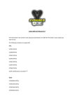
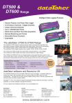
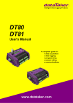
The dataTaker CANgate allows a data logger (such as the dataTaker DT80) or a host computer to be interfaced to a CAN
network. CANgate is equipped with two standard CAN interfaces, plus a serial interface for connecting to an NMEA-0183
compatible device such as a GPS unit. Data may then be returned to the host computer or data logger via a second RS232
interface.
CANgate is capable of performing a range of functions; such as sending and receiving raw CAN messages or performing
higher-level functions to interface with ISO-14230/OBD-II and SAE-J1939 compatible devices.
The CAN ports are "hot-pluggable" and all CANgate settings are saved in non-volatile flash memory so that the unit will
resume its configured tasks following a power interruption.
ECU
CAN bus 1
CAN bus 2
ECU
CAN
CAN
RS232 / NMEA-0183
CANgate
RS232 /
ASCII data/commands
DT80/DT800
Data Logger
or
Host Computer
GPS
12V DC power
Typical CANgate application
About This Manual
This document is primarily a reference manual which describes the commands used to configure the CANgate. It is assumed
that the reader has some familiarity with the operation of CAN-based systems and the various communication protocols
which operate over CAN.
Note that dataTaker DeLogger software provides an easy-to-use "front end" which will generate the required logger and
CANgate commands in order to monitor and record the parameters of interest from the CAN bus. If DeLogger is used then
detailed knowledge of the CANgate commands described in this manual is not required.
UM-0086-A2
CANgate User’s Manual
Page 5
Acronyms
Abbreviation
Meaning
CAN
Controller Area Network
CRLF
Carriage Return, Line Feed
ECU
Electronic Control Unit
GPS
Global Positioning System
ID
Identifier
ISO
International Standards Organisation
NMEA
National Marine Electronics Association
OBD
On Board Diagnostics
PGN
Parameter Group Number
PID
Parameter Identifier
SAE
Society of Automotive Engineers
SPN
Suspect Parameter Number
OBD
On Board Diagnostics
DTC
Diagnostic Trouble Code
PDU
Protocol Data Unit
UM-0086-A2
CANgate User’s Manual
Page 6
CANgate Hardware
Connectors and LEDs
CANgate consists of a small aluminium box with a DE9 connector on each end and six LEDs on the top face.
Host RS232 Port
The female DE9 is used to connect to an RS232 port on a host computer or data logger. The pin-out follows the standard
DTE (Data Terminal Equipment) layout as used on a PC. That is:
Pin
Signal
1
-
Function
2
RXD
Receive Data input
3
TXD
Transmit Data output
4
-
5
GND
6
-
7
RTS
Request To Send output
8
CTS
Clear To Send input
9
-
Ground
Note that the RTS and CTS pins are only used if hardware handshaking is selected (see Configuration (P11))
CAN/GPS/Power Port
The male DE9 is used to:
supply power to CANgate (10-30V DC)
connect to two separate CAN buses
connect to the RS232 interface (and possibly power) on a GPS unit
The pin-out is as follows:
Pin
Signal
Function
1
5V out
+5Vdc output (200mA max)
2
GND
Ground
3
CAN1-HI
CAN port 1 – high (+)
4
GPS RXD
GPS port – Receive Data input
5
CAN1-LO
CAN port 1 – low (–)
6
CAN2-HI
CAN port 2 – high (+)
7
CAN2-LO
CAN port 2 – low (–)
8
GPS TXD
GPS port – Transmit Data output
9
POWER in
+10-30V DC power input
LEDs
The LEDs are used to indicate activity on the various ports:
LED Label
LED Colour
Function
Power
red
on while CANgate is powered
RS232 Tx
red
flashes when characters are transmitted to host port
RS232 Rx
green
flashes when characters are received from host port
CAN 1 Rx
blue
flashes when a CAN frame is successfully received from CAN port 1
CAN 2 Rx
red
flashes when a CAN frame is successfully received from CAN port 2
GPS Rx
green
flashes when characters are received from GPS port
Note that the CAN LEDs will only flash on receipt of CAN frames which match CANgate's current hardware filter settings. If
CANgate has not yet been programmed to receive CAN data then the LEDs will not flash, even if there is traffic on the
connected bus.
UM-0086-A2
CANgate User’s Manual
Page 7
Connecting CANgate
Host Computer Connection
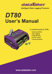
The supplied host computer serial cable is wired as a standard "null modem" cable:
CANgate
1
RXD – 2
TXD – 3
4
GND – 5
6
RTS – 7
CTS – 8
9
1
2 – RXD
3 – TXD
4
5 – GND
6
7 – RTS
8 – CTS
9
DE9 female
Host
Computer
DE9 female
Host computer serial connection wiring diagram
If the host computer does not have an RS232 port then a USB to serial adapter may be used.
Data Logger Connection
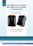
The supplied data logger serial cable is designed to connect to the serial sensor port on a DT80 series logger.
CANgate
1
RXD – 2
TXD – 3
4
GND – 5
6
RTS – 7
CTS – 8
9
BLUE
RED
YELLOW
WHITE
GREEN
1 – Tx Z
2 – Rx A
3 – RTS Y
4 – CTS B
5 – D GND
DT80 series
data logger
terminal block
DE9 female
Data logger serial connection wiring diagram
Note: By default, the CANgate host port operates at a high baud rate (57600 baud). At this speed, the maximum cable length
for the host computer or data logger connection is approximately 5 metres, assuming good quality shielded cable is used. If
a longer cable is required, the CANgate baud rate should be reduced (see Configuration (P11)), eg. at 9600 baud a cable
length of 40m is normally possible.
UM-0086-A2
CANgate User’s Manual
Page 8
CAN/GPS/Power Connections
The supplied terminal adapter plug (DE9 male to 9-way terminal block) provides convenient screw terminal connections to
the CAN/GPS/POWER connector. Alternatively, a custom cable can be made up using a conventional DE9 plug.
A typical wiring configuration is shown below:
Vehicle
Diagnostic
Connector
(SAE J1962)
1
J1850+ – 2
3
CHAS GND – 4
SIG GND – 5
CAN HI – 6
ISO 9141 K – 7
8
9
J1850- – 10
11
12
13
CAN LO – 14
ISO 9141 L – 15
BATTERY – 16
1 – 5V out
2 – GND
3 – CAN1 HI
4 – GPS RXD
5 – CAN1 LO
6 – CAN2 HI
7 – CAN2 LO
8 – GPS TXD
9 – POWER
CANgate
DE9 male
SAE J1962 male
GPS
RXD
TXD
GND
Power
Connector to suit
GPS unit
Diagnostic connector and GPS wiring diagram
Note A vehicle with an SAE J1962 diagnostic connector may not necessarily use a CAN network. If CAN is not used then the
indicated pins will either be not connected or in some applications may have a different function. Ensure that the vehicle does
actually use high speed CAN before connecting CANgate to the diagnostic connector.
CAN Bus Type and Termination
The CAN protocol can operate over a number of different physical layers. A physical layer is a specification defining the low
level electrical characteristics of the network, eg. allowable bit rates, voltage levels, cable type and so on.
It is important to note that CANgate only supports the high speed CAN physical layer, as defined in ISO 11898-2 / SAE
J2284. This is by far the most widely used physical layer. The important characteristics of this standard are:
two wire, 5V differential signalling
bit rate 10kbps – 1Mbps
twisted pair cable, 120 Ω characteristic impedance
A high speed CAN network is required to have a linear topology. There is a single twisted pair "backbone" cable which can
be up to 40m long. Electronic control units (ECUs) are then connected to the bus using short stub connections (max length
0.3m). (These limits are for 1Mbps operation and can be increased somewhat for lower bit rates.)
At each end of the bus, correct termination is required. This typically consists of a resistor (wired across the two bus lines)
that matches the impedance of the cable (ie. 120 Ω). The termination resistance provides the correct DC load for the CAN
output drivers, and minimises signal "reflections", which can distort the CAN signals and cause errors.
UM-0086-A2
CANgate User’s Manual
Page 9
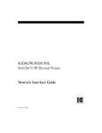
Connecting to an Existing CAN Network
A typical CAN network might be wired as follows:
CAN-HI
ECU 1
120 Ω
CAN-LO
stub
stub
ECU 2
ECU 3
CANgate
DIAG PORT
2.6 KΩ
ECU 4
stub
ECU 5
stub
120 Ω
Typical layout of a vehicular CAN network
In this case the vehicle has five ECUs connected to the CAN bus, plus a diagnostic connector. ECUs 1 and 5 are at the ends
of the main bus, so they incorporate termination resistors. ECUs 2, 3 and 4 connect to the bus via short stub connections and
do not include a termination resistor.
Notice that CANgate incorporates weak termination (2.6k Ω). This value is high enough so as not to significantly increase
the DC load on the already terminated bus, yet low enough to provide some damping of reflections on CANgate's stub
connection to the bus. This allows the length of the stub to be extended to around 2-3 metres. Note that some of the ECUs
may also include weak termination to allow their stub connections to be extended slightly.
Connecting to a Single ECU
If CANgate is connected to a single ECU (eg for laboratory testing) then an external termination resistor may be required
CANgate
2.6 KΩ
60 Ω
ECU
Direct connection to a single ECU
In this case a short (1m) cable is used so the two 120 Ω resistors are combined into one 60 Ω resistor. If a long cable is used
then 120 Ω resistors should be placed at each end. This assumes that the ECU is not terminated (or weakly terminated). If
the ECU includes its own 120 Ω termination then an external 120 Ω resistor is only required at the CANgate end of the cable.
Note that if the cable is short and the bit rate moderate then you may well get away with no external termination, ie.
CANgate's internal weak termination may be adequate.
Inside CANgate
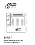
Accessing CANgate Internals
If it is necessary to alter the settings on the internal DIP switch then CANgate will need to be disassembled, as follows:
1.
Disconnect any cables from the CANgate connectors.
2.
Remove the two Philips-head screws on the right hand ("Host RS232") end of the case.
3.
Remove the aluminium end plate and plastic surround.
4.
Push on the connector at the other end of the case. The printed circuit board (PCB) should slide out.
UM-0086-A2
CANgate User’s Manual
Page 10
To reassemble:
1.
Slide the printed circuit board into the topmost slot in the case (the one closest to the front panel label). The male DE9
should be at the right hand ("Host RS232") end of the case.
Note: It is normal for one of the solder connections on the PCB near the male DE9 connector to make contact with the
case.
2.
Replace the plastic surround, then the end plate.
3.
Fasten the two screws
CANgate internal view
Configuration Switches
By default, the CANgate's host RS232 port is configured for 57600 baud, hardware flow control (RTS/CTS), 8 data bits, no
parity, 1 stop bit. This should be suitable for most applications, however these settings can be changed by setting the internal
DIP switch, as shown below. The factory default is all switches OFF.
Host port
baud rate
Switch 1
Switch 2
Switch 3
Switch 4
Switch 5
Switch 6
Switch 7
Switch 8
57600
off
off
off
x
x
x
x
off
38400
off
off
ON
x
x
x
x
off
19200
off
ON
off
x
x
x
x
off
9600
off
ON
ON
x
x
x
x
off
115200
ON
off
off
x
x
x
x
off
x
x
x
off
x
x
x
off
Host port hardware
flow control software
x
x
x
ON
x
x
x
off
Factory Defaults
ON
ON
ON
ON
ON
ON
ON
off
Bootstrap Mode
x
x
x
x
x
x
x
ON
Note: Switch numbers refer to the numbers printed on the switch itself. Ignore the labels marked on the printed circuit board.
Note: The switch settings are only checked immediately after power up. Changing the switches during operation has no
effect.
The Factory Defaults setting can be used to force CANgate to revert to a factory default state, ie. verbose mode off, both
CAN ports disabled, GPS baud rate 4800, all memory slots cleared. Set the switches as indicated above (ie. switches 1-7
ON), then cycle the power – all LEDs should illuminate briefly – then return the switches to their normal setting and cycle the
power again.
The Bootstrap Mode switch provides an alternative way of entering Bootstrap Mode, which is only used when upgrading
CANgate firmware.
UM-0086-A2
CANgate User’s Manual
Page 11
Using CANgate
Memory Slots
By default, CANgate will not send or receive any CAN messages. In order to do anything useful, it must first be programmed.
CANgate is programmed by sending commands to set up one or more memory slots. Each memory slot can be configured
to perform one of the following functions:
Slot type
Class
Action
RECV
RECVE
passive
receive CAN messages with a specified identifier value, extract the specified data field and return
its value as a formatted ASCII value
RECVJ
passive
receive CAN messages relating to a specified J1939 PGN number, extract and return the
specified data field
GPS
passive
receive NMEA-0183 messages of the specified sentence type, extract and return the specified
data field
SEND
SENDE
active
send a CAN message
RQST
active
request an ISO-14230 parameter, wait for the reply, extract and return the specified data field
RQSTJ
active
request a J1939 PGN, wait for the reply, extract and return the specified data field
As can be seen, there are two classes of slots: passive and active.
For RECV, RECVE, RECVJ and GPS slots, CANgate passively receives all matching messages then returns the last known
data value either at a fixed rate, or when requested by the host (data logger or computer). Statistical calculations can
optionally be performed, resulting in a min/max/average value being returned instead of an instantaneous value.
For SEND, SENDE, RQST and RQSTJ slots, CANgate will take the specified action (ie. transmit a message and possibly
wait for a reply) either at a fixed rate or when requested by the host.
In all cases, one memory slot corresponds to one data value of interest. So if a particular type of CAN message contains six
separate values packed into its data area, of which four are of interest, then you would set up four memory slots – each one
configured to extract a different subfield.
Up to 150 memory slots (which are referred to by number, 1-150) can be set up. Slot configurations are automatically saved
to flash memory so that operation will automatically resume following a power interruption.
One further memory slot, Slot 0, is provided. This is intended to be used as a "scratch pad" for one-off requests, ie. it may be
reprogrammed many times during operation. This slot's configuration is not saved to flash.
UM-0086-A2
CANgate User’s Manual
Page 12
Memory Slot Commands and Protocol Hierarchy
CAN networks can use a number of different higher level communications protocols. The following diagram illustrates the
protocols used by each type of memory slot.
RECV
SEND
RECVE
SENDE
RECVJ
RQSTJ
RQST
ISO 14230-3 / OBD-II
Diagnostic Services
Application Layer
SAE J1939-71
Vehicle Application Layer
ISO 15765-2
Network Layer
SAE J1939-21
Data Link / Network Layer
GPS
NMEA-0183
CAN 2.0B PROTOCOL / ISO 11898-2
Data Link / Physical Layer
CAN PORT 1
CAN PORT 2
GPS PORT
CANgate protocol hierarchy
As can be seen, the RECV, RECVE, SEND and SENDE memory slot types operate on raw CAN messages. A raw CAN
message consists of an 11 or 29 bit identifier, plus 8 bytes of data.
RQST memory slots allow parameters to be requested using standard automotive OBD (On Board Diagnostics) requests.
The ISO 15765-2 network layer protocol is responsible for breaking up the request and response messages into multiple
CAN frames, if required.
RECVJ and RQSTJ memory slots allow broadcast and requested parameters to be read from a J1939 network. J1939 also
incorporates a network layer which can break long messages up into multiple CAN frames.
Finally, GPS memory slots allow fields of interest to be extracted from the NMEA-0183 data stream produced by a GPS
device.
Entering Commands
CANgate memory slots and other settings are configured by sending textual commands via the host port. The available
commands are detailed in the Command Reference (P16).
If CANgate is directly connected to host computer then these commands can be entered using a terminal program (eg.
DeTransfer).
If CANgate is connected to the serial sensor port on a DT80/DT800 series data logger then the logger would be programmed
to transmit commands and receive data using the 1SERIAL channel type. Refer to the logger User Manual for more details.
CANgate commands are not case sensitive.
Most commands have a set number of space-separated parameters. All parameters must be specified, unless a parameter
is marked as optional.
A parameter's data type will be specified as either:
floating point – enter a decimal value, eg. 1.25, -4, 0.9907
integer – enter a decimal or hexadecimal value, eg. 2309, 0xff07, -10 (hexadecimal values are prefixed by 0x)
UM-0086-A2
CANgate User’s Manual
Page 13
hex data – enter a string of hexadecimal digits, eg. 12ff09270045db08. To make long strings easier to read, one
or more underscores (or any other non-hex, non-whitespace character) can optionally be inserted between bytes, eg:
12ff0927_0045db08. The hexadecimal prefix 0x can also be included if desired.
string – enter an ASCII string inside quotation marks, eg. "big top", "\007Alert ", "\r\n"
Control characters may be inserted into strings using a backslash followed by three decimal digits representing the ASCII
code, eg. \013 will insert a carriage return. To insert an actual backslash character, use \\. As a shortcut, carriage return,
newline (CR-LF) and tab characters may be inserted using \r, \n and \t respectively.
Note: If DeTransfer is used to send commands to CANgate then each backslash must be entered as \\ in the DeTransfer
Send window. So if you want the string to contain an actual backslash character you would need to enter \\\\ in
DeTransfer.
Commands must be terminated by a carriage return or a semi-colon (;) character.
Comments may be included using an apostrophe (') character. All characters after the apostrophe up until the end of the
line will be ignored.
Run Mode and Program Mode
CANgate has two operational modes.
Run Mode is the normal mode of operation. Following power-up, CANgate always starts in Run Mode.
In Run Mode, all configured memory slots will receive and/or transmit their programmed CAN or GPS messages, and return
data to the host system as required.
Whilst in Run Mode, any of the commands described in the Command Reference (P16) may be entered. However, only
Memory Slot #0's configuration may be changed. Commands that attempt to modify any of the other memory slots will be
ignored – the only way to update these slots is to switch to Program Mode.
Program Mode is entered by sending the BEGIN command. This command will erase all existing memory slots and prepare
CANgate for receiving new definitions.
In Program Mode, the CAN and GPS ports are not active. The only commands that are accepted in this mode are the slot
definition commands – RECV, RECVE, SEND, SENDE, RECVJ, RQST, RQSTJ and GPS.
These commands are prefixed by the number of the memory slot to define, eg:
12 RECV 1 0x712 1 2
will define memory slot #12.
When all required memory slots have been defined, the END command will save all memory slot details (except Slot #0) to
non-volatile flash memory and return to Run Mode.
UM-0086-A2
CANgate User’s Manual
Page 14
Command Summary
{ slot } RECV CANport RxID { startByte{.bit} endByte{.bit} sampleRate } { FORMAT options }
{ slot } RECVE CANport RxID { startByte{.bit} endByte{.bit} sampleRate } { FORMAT options }
{ slot } SEND CANport TxID hexData { sampleRate }
{ slot } SENDE CANport TxID hexData { sampleRate }
{ slot } RQST CANport hexData { startByte{.bit} endByte{.bit} ECUaddr sampleRate } { FORMAT options }
{ slot } RECVJ CANport PGN { startByte{.bit} endByte{.bit} ECUaddr priority sampleRate } { FORMAT options }
{ slot } RQSTJ CANport PGN { startByte{.bit} endByte{.bit} ECUaddr priority sampleRate } { FORMAT options }
{ slot } GPS "header" fieldNum { option sampleRate } { FORMAT options }
… FORMAT { rawFormat } { scale offset } { "formatString" } { stats }
BEGIN
END
RP { slot1 slot2 }
CONNECT CANport bitrate
VERBOSE state
VERSION
RESET
SNOOP CANport | GPS { snoopTime }
SNOOPJ CANport { snoopTime }
NETLOAD { CANport }
SETADDR CANport address
GPSBAUD baudRate
GPSSEND "text"
STATUS
STATS { CLEAR }
DIAG mode
UM-0086-A2
CANgate User’s Manual
Page 15
Command Reference
Commands and Parameters
In this section, literal text (to be entered exactly as shown) is shown thus: RECV.
Variable parameters are shown as: CANport.
Optional parameters are surrounded by braces. If multiple parameters are surrounded by braces, eg.
CMD param1 param2 { param3 param4 }
then one or more of the parameters may be omitted, starting with the rightmost parameter. That is, you can specify either:
CMD param1 param2 or
CMD param1 param2 param3 or
CMD param1 param2 param3 param4
If parameters have their own individual braces, eg.
CMD param1 param2 { param3 } { param4 }
then each optional parameter can be either specified, or not. So as well as the above choices you could also specify:
CMD param1 param2 param4
All optional parameters have a defined default value, which is what will be used if the parameter is not specified.
Remember that CANgate commands are not case sensitive, so recv is equivalent to RECV.
Slot Definition Commands
RECV – Receive Standard-ID CAN Messages
{ slot } RECV CANport RxID { startByte{.bit} endByte{.bit} sampleRate } { FORMAT formatOptions }
where:
slot is the memory slot being defined (integer, 0-150). If not specified then 0 is assumed. If CANgate is in Run Mode
then zero is the only value that can go here.
CANport is the CAN port to use (integer, 1-2)
RxID is the 11-bit CAN identifier to listen for (integer, 0-0x7FF)
startByte{.bit} is the starting bit position of the field of interest within the 8-byte CAN data field. Bytes are numbered
from 1 to 8, bits are numbered from 8 (MSB) down to 1 (LSB). If startByte is not specified then 1 is assumed. If .bit is
not specified then .8 is assumed.
endByte{.bit} is the ending bit position (inclusive) of the field of interest within the 8-byte CAN data field. If endByte is
not specified then 8 is assumed. If .bit is not specified then .1 is assumed.
sampleRate is the rate at which to return values to the host (integer, in ms, must be multiple of 100ms). May also be
ALL, in which case a value is returned on receipt of every matching CAN message. If this parameter is 0 or not
specified, the memory slot will only return data when it is polled by the host system (using the RP command).
formatOptions specify how the data value is to be formatted when it is returned to the host system; see FORMAT
Sub-command (P21) for more details. if not specified, data will be returned in raw hexadecimal format.
A RECV memory slot captures all messages on the specified CAN port with the specified standard identifier, and extracts the
required data field. When polled (using the RP command), or at the intervals specified by the sampleRate parameter, the slot
will return the most recent value for the data field. If no messages have been received, nothing will be returned (other than
the configured static formatting text, which is specified by the FORMAT sub-command and by default is just CRLF).
The SNOOP command (P24) can be used to determine which CAN identifiers are being broadcast on a CAN network.
Note: If the sampleRate parameter is set to ALL, it is not guaranteed that every CAN message will be returned. Many CAN
networks operate at high speed, and some parameters are broadcast at very frequent intervals. The rate at which these
messages arrive may exceed the bandwidth of the host RS232 connection, or the processing capabilities of the CANgate.
Examples
RECV 1 0x220
Receive messages on CAN port 1 with ID 0x220. When polled, return all 8 data bytes (in hexadecimal) of the most recent
message.
RECV 1 0x603 1 2 FORMAT "P1:%d\n"
Receive ID 0x603 messages. When polled, return the first two data bytes as a single decimal integer, prefixed by P1:.
Remember – if DeTransfer is used to send the above command then it would need to be entered as
RECV 1 0x603 1 2 FORMAT "P1:%d\\n"
UM-0086-A2
CANgate User’s Manual
Page 16
RECV 1 0x603 3.8 3.5 ALL FORMAT .25 "%f,"
As each ID 0x603 message is received, return the value of the upper 4 bits of data byte 3 (0-15). This is then scaled by a
factor of 0.25 and returned as a floating point number (range 0-3.75) followed by a comma.
RECV 1 0x112 4 8 1000
Once per second (1000ms), return the most recent values of data bytes 4-8 of received ID 0x112 messages.
RECVE – Receive Extended-ID CAN Messages
{ slot } RECVE CANport RxID { startByte{.bit} endByte{.bit} sampleRate } { FORMAT formatOptions }
This command is exactly the same as RECV, except that the CAN identifier is an extended mode (29 bit) identifier, as
opposed to a standard mode (11 bit) identifier.
The allowable range for RxID is therefore 0-0x1FFFFFFF
SEND – Transmit Standard-ID CAN Message
{ slot } SEND CANport TxID hexData { sampleRate }
where:
slot is the memory slot being defined (integer, 0-150). If not specified then 0 is assumed. If CANgate is in Run Mode
then zero is the only value that can go here.
CANport is the CAN port to use (integer, 1-2)
TxID is the CAN identifier to include in the transmitted message (integer, 0-0x7FF)
hexData is up to 8 bytes of hex data to include in the transmitted message. Non hex characters (eg. _) may be
inserted between bytes to make the string easier to read.
sampleRate is the rate at which to send messages (integer, in ms, must be multiple of 100ms). If this parameter is 0 or
not specified, the memory slot will only send a message when it is polled by the host system (using the RP command).
When polled, a SEND memory slot transmits a raw CAN message. No data is returned to the host system.
Note that it is not possible to set up a RECV slot on the same CAN port to monitor messages sent by CANgate. If this is
required, connect the two CAN ports together and set up the RECV slot on the other port.
Examples
SEND 2 0x302 1122FF07; RP
This will immediately send a CAN message on CAN port 2. The message's identifier will be 0x302 and the data field will be
1122FF07. The DLC (data length code) field in the CAN frame will be set to 4.
SEND 2 0x119 FF110203_040599CC 2000
Every 2000ms, send the indicated 8-byte data field with CAN ID 0x119.
SENDE – Transmit Extended-ID CAN Message
{ slot } SENDE CANport TxID hexData { sampleRate }
This command is exactly the same as SEND, except that the CAN identifier is an extended mode (29 bit) identifier, as
opposed to a standard mode (11 bit) identifier.
The allowable range for RxID is therefore 0-0x1FFFFFFF
RQST – Request OBD Data
{ slot } RQST CANport hexData { startByte{.bit} endByte{.bit} ECUaddr sampleRate } { FORMAT formatOpt }
where:
slot is the memory slot being defined (integer, 0-150). If not specified then 0 is assumed. If CANgate is in Run Mode
then zero is the only value that can go here.
CANport is the CAN port to use (integer, 1-2)
hexData is 1-39 bytes of data to include in the transmitted request message. The first byte is the ISO-14230 mode
byte, the remainder of the data are parameters. The number and meaning of the parameters vary depending on the
mode byte. Non hex characters (eg. _) may be inserted between bytes to make the string easier to read. See OBD-II
Modes and PIDs (P40) for more details on some common OBD request messages.
startByte{.bit} is the starting bit position of the field of interest within the received message. Bytes are numbered from
1, bits are numbered from 8 (MSB) down to 1 (LSB). If startByte is 0 or not specified, a default value is chosen based
on the mode byte. If .bit is not specified then .8 is assumed.
endByte{.bit} is the ending bit position (inclusive) of the field of interest. If endByte is 0 or not specified then this will be
the last received byte in the message. If .bit is not specified then .1 is assumed.
UM-0086-A2
CANgate User’s Manual
Page 17
ECUaddr is the address of the ECU to which to send the request (integer, 0-7, or 256). If 256 is specified (which is
the default), a non-specific request is made. For ECUs which do not use the standard OBD-II CAN IDs, you can
alternatively specify an explicit CAN ID here, in hexadecimal (e.g. 0x220); this is discussed further below.
sampleRate is the rate at which to send messages (integer, in ms, must be multiple of 100ms). If this parameter is 0 or
not specified, the memory slot will only send a message when it is polled by the host system (using the RP command).
formatOpt specify how the data value is to be formatted when it is returned to the host system; see FORMAT
Sub-command (P21) for more details. if not specified, data will be returned in raw hexadecimal format.
A RQST memory slot transmits a request message to an ISO-14230/OBD-II compatible ECU, and waits for a reply. Then:
if a reply is forthcoming, the required bytes are extracted from the reply message, formatted if required, and returned
to the host.
if an ISO-14230 negative reply code is received, this is reported to the user (if the Verbose flag is on), and no data is
returned.
if nothing is received then CANgate will time out after approximately 400ms and abort the request.
The request will be sent using CAN ID (0x7E0 + ECUaddr). If ECUaddr = 256, this indicates a "functionally addressed
request", which will instead be broadcast using CAN ID 0x7DF.
The message data consists of a single mode byte (or service identifier), followed by a variable number of parameters.
Modes 0x01-0x0F are standardised ("legislated") OBD-II modes (defined in SAE-J1979 or ISO-15031), while modes
0x10-0x3F are manufacturer extended modes (specified in ISO-14230, although details of data and parameters are
manufacturer specific).
CANgate will then listen for a response with CAN ID 0x7E8-0x7EF (ECU #0 will reply using ID 0x7E8, ECU #1 with ID 0x7E9,
and so on). The response message's mode byte will be either:
a copy of the request mode byte with bit 6 set – this is a positive response and the mode byte will generally be
followed by one or more data values, or
the value 0x7F – this is a negative response and indicates that an invalid request was made.
All messages are transmitted using the ISO-15765 network layer protocol. This protocol fragments long messages into
multiple CAN frames and then reassembles them.
CANgate recognises a few of the common ISO-14230 mode byte values and sets the default startByte value appropriately,
so that header information in the response is skipped. In particular:
Mode
default startByte
Comment
0x01, 0x02, 0x33
3
skip first 2 bytes (mode, PID) in response
0x22
4
skip first 3 bytes (mode, ID-hi, ID-lo) in response
other
2
skip first byte (mode) in response
All received data, from startByte through to the end of the message (or endByte if specified), will be returned to the host.
Note: The response time for ISO-14230/OBD-II commands depends upon the particular ECU and can vary greatly. CANgate
will only send out one request at a time; if it is asked to make many requests simultaneously then the requests will be placed
in a queue and executed sequentially. If no reply is received within 400ms then CANgate will assume the ECU is dead and
make the next request.
Note: Some ECUs do not use the standard CAN identifier range (0x7E0 – 0x7E7). In this case an arbitrary CAN ID (0x000 –
0x7F7) can be specified explicitly as the ECUaddr. This should be specified in hexadecimal. CANgate will then send the
request using the specified CAN ID, and expect a response with CAN ID ECUaddr + 8. The following two commands are
therefore equivalent:
RQST 1 010C 3 0 1
RQST 1 010C 3 0 0x7E1
In both cases the request will be sent with CAN ID 0x7E1 and the response will be expected to have CAN ID 0x7E9.
Examples
RQST 1 010D FORMAT "%d\n"
When polled, send a message on CAN port 1 requesting the current value (mode = 0x01) of Parameter ID (PID) 0x0D, which
is vehicle speed (see OBD-II Modes and PIDs (P40)). The speed will be returned as a single decimal integer (0-255 km/h)
followed by CRLF.
RQST 1 1800FF00 2 2 0; RP
This will immediately send a message on CAN port 1 to ECU #0 to ReadDTCByStatus (mode = 0x18), returning all currently
active fault codes (parameter byte 1 = 0x00) for all fault code groups (parameter byte 2-3 = 0xFF00). The ECU will return a
mode byte, fault code count, and a variable length string of 3-byte SAE-J2012 format fault codes. The slot selects just fault
code count (byte 2) and returns it in the default format (hexadecimal).
UM-0086-A2
CANgate User’s Manual
Page 18
RECVJ – Receive J1939 Messages
{ slot } RECVJ CANport PGN { startByte{.bit} endByte{.bit} ECUaddr priority sampleRate } { FORMAT fmtOpt }
where:
slot is the memory slot being defined (integer, 0-150). If not specified then 0 is assumed. If CANgate is in Run Mode
then zero is the only value that can go here.
CANport is the CAN port to use (integer, 1-2)
PGN is the J1939 Parameter Group Number (integer, 0-131071)
startByte{.bit} is the starting bit position of the field of interest within the received message. Bytes are numbered from
1, bits are numbered from 8 (MSB) down to 1 (LSB). If startByte is 0 or not specified then 1 is assumed. If .bit is not
specified then .8 is assumed.
endByte{.bit} is the ending bit position (inclusive) of the field of interest. If endByte is 0 or not specified then this will be
the last received byte in the message. If .bit is not specified then .1 is assumed.
ECUaddr is the address of the ECU (source address) from which to receive messages (integer, 0-255, or 256). If
256 is specified (which is the default), messages are received from any source address.
priority (integer, 0-7, default:6) specifies the expected value of the priority field (bits 28-26 in the CAN ID)
sampleRate is the rate at which to return values to the host (integer, in ms, must be multiple of 100ms). May also be
ALL, in which case a value is returned on receipt of every matching CAN message. If this parameter is 0 or not
specified, the memory slot will only return data when it is polled by the host system (using the RP command).
fmtOpt specifies how the data value is to be formatted when it is returned to the host system; see FORMAT
Sub-command (P21) for more details. if not specified, data will be returned in raw hexadecimal format.
A RECVJ memory slot operates in a similar way to a RECVE slot. That is, it listens for CAN messages with a particular
extended identifier, extracts the required data field then returns it to the host when polled (or at regular intervals, or after
every message is received). The difference is in the way the identifier is specified.
The SAE-J1939 protocol assigns meaning to various parts of the 29-bit CAN identifier, as follows:
CAN ID bit
J1939 interpretation
28-26
Priority
25
Reserved
24
Data Page, which is effectively bit 16 of the PGN
23-16
Parameter Group Number (PGN) MSB (bit 15-8) – if < 240 then this identifier has PDU1 (directed
message) format, otherwise it has PDU2 (broadcast message) format
15-8
if PDU1 format: destination address (implied PGN LSB = 0)
if PDU2 format: PGN LSB, or "group extension" (implied destination address = 0)
7-0
source address
CANgate will receive messages where:
the Priority field matches priority, and
the 17-bit PGN/Datapage fields match PGN (for PDU1 format, any destination address will be accepted), and
the source address field matches ECUaddr (if ECUaddr = 256, any source address will be accepted).
PGN numbers, and the layout of the data fields therein, are defined in the SAE J1939/71 (Vehicle Application Layer)
standard.
The SNOOPJ command (P24) can be used to determine which J1939 PGNs are being broadcast on a CAN network. See also
J1939 PGNs & SPNs (P28).
The J1939 protocol also supports multi-packet broadcast messages. These messages use a fixed PGN value in the CAN
identifier (PGN 59904, 60160 or 60416); the actual PGN is embedded in the CAN data field. CANgate will receive
multi-packet broadcasts where the embedded PGN value matches PGN.
Note that there are some special considerations to be aware of regarding multi-packet transfers; see Multi-Packet J1939
Messages (P30).
Examples
RECVJ 2 61444 1 8 256 3
Receive messages on CAN port 2 (from any ECU) which relate to PGN 61444 – which contains various engine controller
parameters – and return the entire message to the host when polled. Only messages with priority 3 will be received.
UM-0086-A2
CANgate User’s Manual
Page 19
RQSTJ – Request J1939 Data
{ slot } RQSTJ CANport PGN { startByte{.bit} endByte{.bit} ECUaddr priority sampleRate } { FORMAT fmtOpt }
The parameters for a RQSTJ slot are the same as for a RECVJ slot (except that ALL is not a valid setting for sampleRate),
but they are used in a somewhat different way.
When a RQSTJ slot is polled, CANgate will send a message to request a particular parameter group (PGN). The format of
this request message is defined in SAE J1939/21 (Data Link Layer). The request will be sent to destination address
ECUaddr, or to the broadcast address if ECUaddr = 256. The source address will be set to CANgate's configured address
(see SETADDR – Set CANgate Address (P25)).
CANgate will then listen for a response with an appropriate CAN identifier, the same as a RECVJ slot.
Some PGNs have more than 8 bytes of data (which is the limit of a single CAN frame) associated with them. In this case the
ECU will respond with a multi-packet transfer. This may take the form of a multi-packet broadcast, or it may be a
point-to-point transfer using the J1939 transport protocol. CANgate will accept either type of response.
Note that there are some special considerations to be aware of regarding multi-packet transfers; see Multi-Packet J1939
Messages (P30).
See also Request PGNs (P29).
Note: As is the case with ISO-14230 (RQST slots), the response time will depend upon the particular ECU. J1939 requests
are queued in the same way as ISO-14230 requests – CANgate will only send out one request at a time, and will time out
after approximately 400ms if there is no response.
Examples
RQSTJ 2 65254 1 1 0 6 1000 FORMAT .25
Once per second (1000ms), send a request on CAN port 2 for PGN 65254 (time/date) to the ECU with address 0, and expect
a reply with priority 6. The first byte of the response (seconds x 4) is extracted and returned.
GPS – Receive NMEA-0813 Messages
{ slot } GPS "header" fieldNum { option sampleRate } { FORMAT formatOptions }
where:
slot is the memory slot being defined (integer, 0-150). If not specified then 0 is assumed. If CANgate is in Run Mode
then zero is the only value that can go here.
header is the NMEA-0183 sentence header string, without the leading $ character (string, eg."GPGLL")
fieldNum specifies the data field of interest in the NMEA-0183 string (integer, 1-19). The field immediately following
the sentence header is field #1.
option (single character: D or M or N, default:N). If N (normal) is specified then the indicated field is returned as is.
Otherwise, the indicated field and the next field are interpreted as a latitude or longitude value with format
DDDMM.mmmmm,h – DDD = degrees, MM.mmmmm = minutes, h = hemisphere (N, S, E or W). If option = D then
the degrees component is returned, ie. DDD, which will be prefixed by a minus sign if h = S or W. Similarly, if option =
M then the minutes component is returned, ie. MM.mmmmm, which will also be prefixed by a minus sign if h = S or W.
sampleRate is the rate at which to return values to the host (integer, in ms, must be multiple of 100ms). May also be
ALL, in which case a value is returned on receipt of every matching GPS message. If this parameter is 0 or not
specified, the memory slot will only return data when it is polled by the host system (using the RP command).
formatOptions specify how the data value is to be formatted when it is returned to the host system; see FORMAT
Sub-command (P21) for more details. Note that GPS data is always treated as a string; scaling options will be ignored.
The FORMAT clause is therefore only useful for adding before and after text.
If a GPS receiver is connected to CANgate then positional data (latitude, longitude, elevation, etc.) can be returned along
with measured CAN parameters.
A GPS receiver will transmit position messages via its RS232 interface, typically about once per second. These messages
are formatted according to the NMEA-0183 protocol. NMEA-0183 defines many different sentences, each of which consists
of an identification string followed by a number of comma separated data values. For example, the sentence:
$GPGLL,3749.1965,S,14458.9940,E,073510.22,A
provides a basic positional fix, containing the current latitude (37° 49.1965' S, 144° 58.9940' E), and the time the fix was
taken (07:35:10.22 UTC). Other sentence types (eg. $GPGGA) provide more detailed information, including elevation,
accuracy, number of satellites in view, etc.
A CANgate GPS memory slot is used to parse incoming NMEA-0183 data and then return specific fields to the host. This will
capture all messages with the specified ID string, and extract the required data field. When polled (using the RP command),
or at the intervals specified by the sampleRate parameter, the slot will return the most recent value for the data field. If no
messages have been received, or if the specified field does not exist in the received messages, then nothing will be returned
(other than the configured static formatting text, which is specified by the FORMAT sub-command and by default is just
CRLF).
UM-0086-A2
CANgate User’s Manual
Page 20
Examples
GPS "GPGLL" 1 D 5000
Receive NMEA-0183 "GPGLL" sentences. Every 5 seconds, return the current degrees component (-37 for the above input
data)
GPS "GPGSV" 3
When polled, return the number of satellites in view (the third field in a "GPGSV" sentence).
FORMAT Sub-command
As indicated above, all slot definition commands that return a data value may include a FORMAT clause to specify how the
data value should be formatted – otherwise the data will be returned in raw hexadecimal form. The format of a FORMAT
sub-command is as follows:
FORMAT { rawFormat } { scale offset } { "formatString" } { stats }
where:
rawFormat specifies how the raw bit field is to be interpreted. It consists of two letters, one being U or S (unsigned or
2's complement signed; default: U), the other M or N (Motorola (MSB first) or Intel (LSB first); default: M). Note that for
J1939 memory slots (RECVJ, RQSTJ), Intel format is always used. The byte swapping options are ignored if the size
of the data field is not a multiple of 8 bits.
scale is a floating point scaling factor which will be multiplied by the raw bit field value (default: 1.0).
offset is a floating point offset which will be added to the scaled bit field value (default: 0.0).
formatString is a string which specifies: the output type (raw hexadecimal, integer, floating point, string, etc.),
formatting options (eg. number of decimal places) and any leading or trailing text. Default is "%f\n" (output floating
point value, 2 decimal places, followed by CRLF) See below for more details.
stats is a statistical operation (MIN, MAX or AVE). If set, all matching CAN messages are received and processed.
When the slot is polled, the calculated minimum, maximum or average value (since last poll) is returned. If not
specified (which is the default), the most recent instantaneous data value is returned. Note: statistical operations are
only valid for passive CAN slot types (RECV, RECVE, RECVJ)
Format String
A format string consists of three text elements:
some text to display before the data value (default: none)
a conversion specifier, which begins with a % character and specifies the data type (integer, floating point etc.) and
possibly some other formatting details. If no conversion specifier is present (which is the default), the data value will be
output in raw hexadecimal format, exactly as it appears in the CAN message (in this case the rawFormat, scale, offset
and stats parameters will be ignored.)
some text to display after the data value (default: \n). If no conversion specifier is present, all text in the format string
will be returned after the data value.
The format of the conversion specifier is as follows (there are no gaps between the various elements):
% { flag } { width }{ .precision } type
where:
% marks the start of the conversion specifier
type is a single character which specifies the data type: f (floating point), d (signed decimal integer), u (unsigned
decimal integer), x/X (unsigned lower/upper case hexadecimal integer) or s (ASCII string)
flag is a single character which alters the way the other elements work, as described in width below (default: none)
width is an integer, the minimum number of characters to output. If the converted data value is longer than width then
all characters will still be output. If the data value is shorter then it will be padded on the left with spaces (or zeroes, if
flag = '0') so that a total of width characters are output. If flag = '-' then the data value will instead be padded on the
right with spaces if it is shorter than width. The default value for width is 0, ie. no padding characters will be inserted.
precision is an integer which specifies different things depending on the data type. For floating point, it is the number of
digits displayed to the right of the decimal point (default: 2). For integers, it is the minimum number of displayed digits;
if the data value has fewer digits it will be prefixed by zeroes (default: 0). For strings, it is the maximum number of
characters to display, If the data string is longer then it will be truncated (default: no maximum).
Note that following points about format strings:
An integer (d/u/x/X) or floating point (f) conversion specifier will be ignored if the data field is larger than 32 bits. In
this case the value will be returned in raw hexadecimal format.
Integer or floating point conversion specifiers are ignored for GPS slots. For a GPS slot, all data values are treated as
strings.
UM-0086-A2
CANgate User’s Manual
Page 21
The floating point conversion only supports values in the range -16777216 to 16777216. Values outside this range will
be returned as 99999.9.
If an integer conversion type is specified, the scale and offset parameters will be converted to integers.
The format strings "%X\n" and "\n" do different things. The former will output the scaled data value as a
hexadecimal number; the latter will output the raw data value as it appears in the CAN message (no byte reversal,
scaling, etc.)
To include a literal % or \ character, enter %% or \\ respectively.
Defaults
To summarise the rules regarding default formatting behaviour:
if FORMAT is present, with a formatString, and the format string contains a conversion specifier, then the data will be
formatted according to the conversion specifier. (Numeric conversion specifiers will only work if the data size is 32 bits
or less, if it is longer then the data will be returned in raw hexadecimal format.)
if FORMAT is present, with a formatString, and the format string does not contain a conversion specifier, then the data
will be returned in raw hexadecimal form (or ASCII string form for GPS slots), followed by the format string text.
if FORMAT is present, without a formatString, then a default format string will be used: "%f\n" for CAN slots, or
"%s\n" for GPS.
if FORMAT is not present, then a default format string will be used: "\n" for CAN slots (ie. raw hexadecimal followed
by CRLF), or "%s\n" for GPS.
Examples
The following examples assume that the last matching CAN message had the data: 01234567AABBCCDD.
RECV 1 0x100 1 2 – returns 0123 CR LF.
RECV 1 0x100 1 2 FORMAT 100 – returns 29100.00 CR LF. (0123 hex, scaled by 100)
RECV 1 0x100 1 2 FORMAT ";" – returns 0123;
RECV 1 0x100 1 2 FORMAT "%d %%\n" – returns 291 % CR LF. (0123 hex)
RECV 1 0x100 1 2 FORMAT N "x=%d Pa\n" – returns x=8961 Pa CR LF. (2301 hex)
RECV 1 0x100 1 8 FORMAT "%d\n" – returns 01234567AABBCCDD CR LF. (no conversion if > 32 bits)
RECV 1 0x100 1 2 FORMAT .5 10 "%9.3f\n" – returns
155.500 CR LF. (2 leading spaces)
RECV 1 0x100 1 2 FORMAT .5 10 "%09.3f\n" – returns 00155.500 CR LF. (2 leading zeroes)
RECV 1 0x100 1 2 FORMAT .5 10 "%-9.3f\n" – returns 155.500
CR LF. (2 trailing spaces)
RECV 1 0x100 1 2 FORMAT .5 10 "%f," – returns 155.50,
RECV 1 0x100 4.8 4.6 FORMAT "Z\t%d" – returns Z TAB 3 (byte 4 = 67 hex, bits 8:6 = 011 binary = 3)
The following assume that the last received GPS string was: $GPGLL,1244.98,S,11102.09,E
GPS "GPGLL" 2 FORMAT ">%3s<" – returns >
S<.
GPS "GPGLL" 3 M FORMAT ">%.4s<" – returns >02.0<. (truncate minutes (02.09) to 4 chars)
Other Commands
With the exception of END, all of the following commands are only valid in Run Mode.
BEGIN – Begin Program Entry
BEGIN
This command erases all memory slots and switches CANgate to Program Mode. In Program Mode, the only commands
that are accepted are numbered slot definition commands. The CAN and GPS interfaces are disabled in Program Mode and
no memory slots are processed.
END – Finish Program Entry
END
This command saves all defined memory slots to flash memory, then switches to Run Mode. Once in Run Mode, no more
numbered memory slots can be defined. However, Slot 0 (which is not saved to flash) may be defined and re-defined any
number of times by entering an unnumbered slot definition command.
UM-0086-A2
CANgate User’s Manual
Page 22
RP – Poll Memory Slot
RP { slot1 slot2 }
where:
slot1 is the first memory slot to poll (0-150, default:0)
slot2 is the last memory slot to poll (0-150, default:0)
This command will poll memory slots slot1 to slot2 inclusive. If no parameters are specified then Slot 0 is polled.
What does polling a slot mean?
For a passive memory slot (RECV, RECVE, RECVJ or GPS), the most recent received value is formatted and
returned to the host. Alternatively the minimum, maximum or average (calculated since the last poll) may be returned
instead, if the FORMAT clause specifies to do so. If no data at all have been received then no value will be returned.
For an active memory slot (SEND, SENDE, RQST, RQSTJ ), CANgate will transmit the required CAN message. In
the case of the request types, CANgate will then wait for a response and return the required data to the host.
If no response is received to a request, or if no data at all have been received at the time that a passive slot is polled, then no
value will be returned. If there was text specified in the format string then that text it will still be returned.
If any slots in the specified range have not been defined then they will be skipped (nothing will be returned for the undefined
slots).
Note: When passive slots are polled, the data is returned instantly, while for RQST/RQSTJ slots the data will only be
returned when a response is received from the ECU. This means that if a mixture of "receive" and "request" slots are polled
all at once then the order of responses may not match the order of the memory slots.
Examples
RP 1 150
Poll all defined memory slots.
RQSTJ 2 65226 3 6 FORMAT "%f\n"; RP
SEND 1 0x142 112233; RP
The RP command is often appended when defining an active memory slot in Slot 0. This usage is not applicable to passive
slots because at the point where the RP command is executed it is unlikely that any data has been received since the slot
was defined, so nothing will be returned.
CONNECT – Set CAN Bit Rate
CONNECT CANport bitrate
where:
CANport is the CAN port to use (integer, 1-2)
bitrate is the CAN bitrate in kbps (integer, 0, 10, 20, 50, 125, 250, 500, 1000)
Before a CAN port can be used it is necessary to specify the bitrate using the CONNECT command.
Initially, the bitrate is set to 0, which will disable the port. If the bitrate is set incorrectly, bus errors will result and the port will
be disabled for a period of two seconds, after which CANgate will re-attempt connection.
The currently selected bitrate setting is saved to flash memory, so it will automatically be set if CANgate restarts following a
power interruption.
Examples
CONNECT 2 250
Configure the CAN port 2 for connection to a 250kbps CAN network. (Note that J1939 based CAN networks always use a
bitrate of 250kbps.)
VERBOSE – Enable Extended Messages
VERBOSE state
where
state is either ON or OFF. Default is OFF.
In Verbose mode, CANgate will return error and confirmation messages as required. Also, all received commands will be
echoed back to the host computer. This is useful for troubleshooting.
In Normal (non-verbose) mode, no unsolicited messages are returned to the host. Data values are returned, as is text that is
generated in direct response to a command (eg VERSION). Commands are not echoed.
UM-0086-A2
CANgate User’s Manual
Page 23
Verbose mode should normally be switched on when manually entering CANgate commands and slot definitions. Once you
are confident that the slots are working as expected, Verbose mode can be turned off.
When CANgate is being controlled by a DT80/800 data logger, Verbose mode is normally switched off. This avoids any
parsing complications which may occur due to unexpected messages returned by CANgate.
The current Verbose mode setting is saved to flash memory so it will be restored following a power interruption.
VERSION – Display Firmware Version
VERSION
This command will return the version number of the CANgate firmware, eg. 1.24, followed by CRLF.
In Verbose mode, the product name is also included.
The VERSION command is a useful check that the host port communications are correctly configured and CANgate is
responding, as it should always return some text in response to this command.
RESET – Clear Memory Slots
RESET
This command will clear all defined memory slots. It does not affect the currently configured CAN/GPS bit rates, or the
current verbose mode setting.
SNOOP – Report CAN/GPS Activity
SNOOP port { snoopTime }
where
port is either the CAN port number (1 or 2), or GPS.
snoopTime is the time to spend listening (integer, in ms, must be multiple of 100ms). Default is 10000 (10 seconds).
This command may be used to determine which CAN identifiers are being broadcast on a CAN network. During the specified
snoop time, all incoming CAN messages on the specified port are received. For each distinct CAN identifier that was
received, the following information is displayed:
identifier type: standard 11 bit (STD) or extended 29 bit (EXT)
identifier value, in hexadecimal
the 64-bit data value from the first received message with this identifier
If GPS is specified instead of a CAN port number, this command will display all NMEA strings that are received during the
snoop period. This is useful for verifying that the GPS unit is sending the expected strings.
Examples
SNOOP 1
EXT 18FEF000
EXT 18F0000F
EXT 18EBFF00
EXT 18ECFF0F
EXT 18EBFF0F
EXT 18FEEE00
END SNOOP
FFFFFF0000F0CCFF
C07DFFFF0FFFFFFF
0115FF5E0004016F
20130003FFE1FE00
010306602254A041
17FF0020FFFFFFFF
This shows that 6 different extended identifiers were captured on CAN port 1 during the default 10 second snoop time.
SNOOP GPS 5000
$GPGLL,5330.25,N,00215.31,W,134531,A
$GPGLL,5330.25,N,00215.31,W,134532,A
$GPGLL,5330.25,N,00215.32,W,134533,A
$GPGLL,5330.24,N,00215.32,W,134534,A
$GPGLL,5330.23,N,00215.32,W,134535,A
This shows the strings received from a GPS unit over a 5 second period.
SNOOPJ – Report J1939 Activity
SNOOPJ port { snoopTime }
This works in exactly the same way as SNOOP, except that the results are interpreted in terms of the J1939 protocol. That is,
the PGN, priority, source address and destination address components of the CAN identifier are decoded.
This command also recognises J1939 multi-packet messages. For such messages the displayed PGN is extracted from the
data field, not the identifier. (For multi-packet messages, the PGN encoded into the CAN identifier relates to the transport
UM-0086-A2
CANgate User’s Manual
Page 24
protocol used to break up and reassemble long messages, not the actual data parameters.)
Examples
SNOOPJ 2
EXT 0CF00400
EXT 18FEF000
EXT 18F0000F
EXT 0CF00300
EXT 18FEF100
EXT* 18ECFF00
EXT 18FEFF00
EXT* 18ECFF00
EXT* 18ECFF0F
END SNOOP
FE7D7D000000FFFF
FFFFFF0000F0CCFF
C07DFFFF0FFFFFFF
F9FE00FFFFFFFFFF
FF000050000000C0
202E0007FFCAFE00
FDFFFFFFFFFFFFFF
20220005FFE3FE00
20130003FFE1FE00
PGN:61444
PGN:65264
PGN:61440
PGN:61443
PGN:65265
PGN:65226
PGN:65279
PGN:65251
PGN:65249
PRI:3
PRI:6
PRI:6
PRI:3
PRI:6
PRI:6
PRI:6
PRI:6
PRI:6
SA:0 DA:0
SA:0 DA:0
SA:15 DA:0
SA:0 DA:0
SA:0 DA:0
SA:0 DA:255 LEN:46
SA:0 DA:0
SA:0 DA:255 LEN:34
SA:15 DA:255 LEN:19
In this example six different single-packet parameter group messages were observed. For each, the PGN, priority, source
address and destination address are returned.
There are also three different multi-packet messages, indicated by EXT*. These include an additional display item: the
length of the data message in bytes. Note that the displayed 64-bit data field does not contain any actual message data; it
contains transport protocol information including PGN and data length.
NETLOAD – Measure CAN Traffic Load
NETLOAD { CANport }
where
CANport is the CAN port to measure (integer, 1-2). If not specified, both CAN ports are measured.
This command measures the traffic load on one or both CAN ports, and reports it as a percentage of the theoretical
maximum for the bit rate in use. It should be noted that a network with a load approaching 80% is close to the practical
maximum load possible on a CAN network.
Examples
NETLOAD
CAN1 0.0 %
CAN2 7.8 %
In this case nothing is connected to CAN1, and a single ECU is connected to CAN2. 7.8% of the available bus bandwidth is
being consumed by the regular broadcasts from this ECU.
SETADDR – Set CANgate Address
SETADDR CANport address
where
CANport is the CAN port (integer, 1-2)
address is the protocol address which CANgate should use when communicating on the specified CAN network
(integer, 0-255, default:0)
For some CAN protocols, each device on the network needs to have a unique address assigned. This command allows you
to assign an address to the CANgate. Currently this will only have an effect for the J1939 protocol. Note that in most cases
the default address (0) can be used.
GPSBAUD – Set GPS Port Baud Rate
GPSBAUD baudRate
where
baudRate is the required baud rate to use on the GPS port (integer, 300-115200, default:4800)
Most NMEA-0183 devices operate at 4800 baud, however some newer high speed devices operate at a faster rate. This
command allows the GPS port baud rate to be set to match that of the connected device.
The current GPS port baud rate setting is saved to flash memory so it will be restored following a power interruption.
UM-0086-A2
CANgate User’s Manual
Page 25
GPSSEND – Send Commands to GPS
GPSSEND "text"
where
text is a text string to send to the GPS port. Escape sequences eg \n, \009 will be translated into the appropriate
control characters.
Some GPS devices can be configured – for example to switch certain NMEA-0183 strings on or off – by sending commands
to them via their serial interface. The GPSSEND command allows you to send arbitrary command strings to the GPS. If the
GPS requires that commands be terminated by a CRLF then include \n at the end of the string.
Examples
GPSSEND "$PGRMO,GPVTG,0\n"
This command will configure a Garmin GPS unit to not output the GPVTG sentence type.
STATUS – List Memory Slot Status
STATUS
This command returns a summary of all defined memory slots. The information returned includes:
memory slot number (0-150)
type of memory slot (RECV, RQST, etc.)
port number (CAN1 or CAN2)
CAN identifier and 8-byte data field to use in transmitted message (SEND, SENDE, RQST, RQSTJ only)
CAN identifier to look for in received message (RECV, RECVE, RECVJ, RQST, RQSTJ only)
GPS header and field number to look for (GPS only)
Start and end byte/bit number of field of interest (RECV, RECVE, RECVJ, RQST, RQSTJ only)
Internal status information ("flags")
sample period
This command can be useful for verifying that all required memory slots have been created successfully. Recall that in
non-verbose mode no error messages will be issued if an invalid slot definition is entered.
Example
STATUS
****** CHANNEL TABLE ******
0: RQST (CAN1) - TxID:0x07df
RxBytes:2.8-end Flags:c0820000
1: RECV (CAN1) - RxID:0x0001
2: RECV (CAN1) - RxID:0x0002
3: RECV (CAN1) - RxID:0x0003
6: RECVE (CAN1) - RxID:0x0006
7: RECVE (CAN1) - RxID:0x0007
***************************
TxData:041800ff
Sample:0 ms
RxBytes:1.8-1.1
RxBytes:1.8-1.1
RxBytes:1.8-1.1
RxBytes:1.8-1.1
RxBytes:1.8-1.1
00000000
RxID:0x07df
Flags:c0020000
Flags:c0020000
Flags:c0020000
Flags:c0220000
Flags:c0220000
Sample:0
Sample:0
Sample:0
Sample:0
Sample:0
ms
ms
ms
ms
ms
STATS – Display Communications Statistics
STATS { CLEAR }
This diagnostic command displays communications statistics for each port (host, GPS, CAN1, CAN2). These include:
volume of traffic sent (Tx) and received (Rx), measured in bytes for the serial ports, and in frames for the CAN ports
number of transmit bytes/frames that could not be sent (Dropped Tx). This may occur if the slot sample rates are set
too fast, so that the volume of traffic required to be sent exceeds the available bandwidth on the port.
number of bytes/frames that could not be received and/or processed (Dropped Rx). This may occur if the slot
sample rates are set such that CANgate cannot keep up with the rate of incoming messages.
number of bytes/frames which were discarded due to errors. These may be due to electrical noise or incorrect bit rate
settings. Note that for CAN ports, "arbitration lost" (ArbLost) errors are a normal part of operation and simply
indicate that a CANgate transmission was delayed by a higher-priority message.
number of CANgate system errors, including RQST/RQSTJ queue overflows and processing overflows (occasions
when the configured slot sample rates could not be met due to excessive processing load)
an indication as to whether an exception (serious CANgate error that required a firmware restart) has occurred.
If the CLEAR parameter is specified then all statistics values are reset.
UM-0086-A2
CANgate User’s Manual
Page 26
Example
STATS
HOST: Tx:218408 Rx:1255 bytes
Dropped Tx:0 Rx:0
Errors:0
GPS: Tx:0 Rx:0 bytes
Dropped Tx:0 Rx:0
Errors:0
CAN1: Tx:44 Rx:272042 frames
Dropped Tx:0 Rx:9
Errors Warning:0 Bus:0 ArbLost:5
CAN2: Tx:0 Rx:273096 frames
Dropped Tx:0 Rx:220
Errors Warning:0 Bus:0 ArbLost:0
Sys: RQST dropped:0
Proc ovfl:0
Except: 0/0
DIAG – Set Diagnostic Mode
DIAG mode
This command enables certain diagnostic functions. Each bit of the mode parameter enables a particular function, as
follows:
if bit 0 = 1 then all CAN messages sent by CANgate will be displayed, eg:
CAN2 TX> 18EC00FF
132C0007 FFEBFE00
which shows that a message has been sent on CAN2 with identifier 0x18EC00FF and the indicated data value.
if bit 1 = 1 then all CAN messages received by CANgate will be displayed, eg:
CAN2 RX< 18EBFF00
07A50403 12FFFFFF
Note that only those messages which match the current filter criteria (as specified by the defined memory slots) will be
received and displayed. So if there are no memory slots defined then nothing will be displayed.
To switch on display of both transmitted and received messages you would therefore use:
DIAG 3
and to switch off all diagnostic displays use:
DIAG 0
This command can be useful when troubleshooting ISO-14230 and J1939 multi-packet request sequences.
UM-0086-A2
CANgate User’s Manual
Page 27
Notes and Examples
Extracting and Formatting Bit Fields
In the following example two 16-bit fields plus four 4-bit fields are packed into the CAN message with identifier 0x118. The
most recent value for each of these fields will be returned when polled by the host.
CONNECT
BEGIN
12 RECV
13 RECV
14 RECV
15 RECV
16 RECV
17 RECV
END
1 500
'Enable CAN port 1 at 500kbps
1
1
1
1
1
1
1 2
3 4
5.8
5.4
6.8
6.4
0x118
0x118
0x118
0x118
0x118
0x118
FORMAT "P1:%d\n"
5.5
5.1 FORMAT 10 -40
6.5 FORMAT .25 "Gibble Freq. %6.3f Hz\n"
6.1
So if the last message that CANgate received (with CAN ID 0x118) happened to have the following 64-bit data field:
019266401A9F0000
and the above six memory slots were polled, for example using the command:
RP 12 17
then the following data would be returned:
P1:402
(bytes 1-2 = 0x0192 = 402)
(bytes 3-4 = 0x6640)
6640
(byte 5 = 0x1A, bits 8-5 = 0x1)
01
(byte 5 = 0x1A, bits 4-1 = 0xA, scaled by 10 with offset -40 = 60)
60.00
Gibble Freq. 2.250 Hz (byte 6 = 0x9F, bits 8-5 = 0x9, scaled by 0.25 = 2.25)
(byte 6 = 0x9F, bits 4-1 = 0xF)
0F
In this case three of the memory slots use the FORMAT specifier to return their values in scaled engineering units, rather than
raw hexadecimal. Slot #15 uses the default format string of "%f\n", ie. floating point, 2 decimal places, followed by CRLF.
J1939 PGNs & SPNs
Broadcast PGNs
J1939 based systems typically have a multitude of SPNs (Suspect Parameter Numbers), each representing an individual
measured quantity or status. A group of related SPNs will be broadcast over the CAN network under a particular Parameter
Group Number (PGN), which is specified as part of the 29 bit identifier.
Each 29 bit identifier carries with it one 64 bit packet of CAN data. Some PGNs with a data length larger the 64 bits require
several packets to send them. CANgate automatically uses the J1939 transport protocol to send or receive large PGNs.
Refer to RQSTJ – Request J1939 Data (P20) or the SAE J1939/21 (Data Link Layer) standard for a more detailed description
on PGN numbers and how they are encoded into CAN identifiers.
An example of a J1939 SPN would be “Engine Speed”. In order to capture engine speed using CANgate, it is first necessary
to determine the PGN which contains this parameter. This can be found in SAE J1939/71 (Vehicle Application Layer), which
specifies:
Electronic Engine Controller #1
Update rate:
Engine speed dependent
Data length:
8 bytes
Data page:
0
PDU format:
240
PDU specific:
4
Default priority 3
Parameter Group Number: 61,444 (0x00F004)
Byte: 1
Status_EEC1
Bit: 8-5
Not defined
Bit: 4-1
Engine/retarder torque mode
Byte: 2
Driver’s demand engine – percent torque
Byte: 3
Actual engine – percent torque
Byte: 4-5
Engine Speed
Byte: 6-8
Not defined
The precise format of each SPN is also specified in SAE J1939/71:
Engine Speed
Data Length:
Resolution:
UM-0086-A2
2 bytes
0.125 rpm/bit gain, 0 rpm offset
CANgate User’s Manual
Page 28
Data Range:
0 to 8031.875 rpm
Type:
Measured
Suspect Parameter Number:190
The SNOOPJ command can now be used to verify that the PGN is in fact being broadcast by an ECU on the CAN network.
This involves examining the returned data looking for the required PGN (61444). For example:
SNOOPJ 1
…
EXT
0CF00402 PGN:61444 PRI:3 SA:2 DA:0
…
This line indicates that the required PGN is being broadcast on the network, and decodes the CAN identifier (0CF00402) as
follows:
priority field is 3
PGN field is 61444 (0x00F004)
destAddr field is not applicable because this PGN uses PDU2 format (bits 15-8 of PGN >= 0xF0)
srcAddr (ie. the address of the sending ECU) is 2.
Using this information, a memory slot can be initialised, for example:
RECVJ 1 61444 4 5 2 3 FORMAT 0.125 "%.3f rpm\n"
which will:
receive J1939 messages
on CAN port 1
with identifier 0x0CF00402 (PGN 61444, source address 2, priority 3)
and extract bytes 4-5 as an unsigned 16-bit value (byte 4 = LSB, byte 5 = MSB)
then multiply by 0.125
and, when polled, return the result as a floating point value with 3 decimal places (%.3f)
followed by the text " rpm" and a CRLF (\n).
Note that for J1939, multi-byte fields are always specified LSB first (Intel format). It is not necessary to specify the n option
after the FORMAT for RECVJ/RQSTJ slots.
Request PGNs
Some PGNs are not broadcast; they are only returned when specifically requested. For example, if the above PGN was
actually a "request-only" PGN, the engine speed would then be obtained using:
RQSTJ 1 61444 4 5 2 3 FORMAT .125 "%.3f rpm\n"; RP
which looks very similar to the RECVJ slot definition. The RP on the end causes the memory slot to be immediately polled,
which will cause the request to be immediately sent. (Note that it doesn't make sense to poll a RECVJ slot immediately after
defining it, because at that time it is likely that no matching messages will have been received, in which case nothing will be
returned.)
Reusing Request Data
Often a J1939 PGN will contain several separate parameters (which is why it is called a Parameter Group Number). These
parameters are typically extracted using a number of memory slots, all with the same PGN but with different start and end
bytes specified. The same is true for certain OBD PIDs.
For requested PGNs, it is inefficient for each slot to send a separate request, particularly for multi-packet PGNs. Also, you
may not get a consistent snapshot of all of a PGN's constituent parameters – that is, they may not have been measured at
the same time (which may or may not be a problem).
For this reason, CANgate will attempt to reuse requested data where possible, ie. a RQST/RQSTJ slot will use previously
received reply data rather than sending a new request. This will, however, only be done if:
the most recently sent request message exactly matches this slot's request message (ie. it's a request for the same
PGN, same source and destination address and so on), and
this is a different slot to the one which sent the request (or, if this and the requesting slot are both slot #0, then the two
slot definitions are different in some way, eg. they are extracting a different range of bytes), and
the reply data was received less than 5 seconds ago.
The second condition means that if you repeatedly poll a group of slots, each of which extracts a different part of the same
PGN, then only one request will be sent each time the group is polled – provided that the group is polled within 5 seconds.
UM-0086-A2
CANgate User’s Manual
Page 29
Example
J1939 PGN 65254 may be used to request the current time setting from an ECU. This PGN contains separate fields for
hours, minutes and seconds. It is important that this PGN be queried using a single request, otherwise the time may roll over
to the next minute/hour between requests, leading to an incorrect reading.
The following group of slot definitions will, when polled (using RP 1 3), return the current time in hh:mm:ss format.
BEGIN
1 RQSTJ 1 65254 3 3 FORMAT "%02d:"
' hours
2 RQSTJ 1 65254 2 2 FORMAT "%02d:"
' minutes
3 RQSTJ 1 65254 1 1 FORMAT .25 "%0.f\n" ' seconds
END
Sending the following slot #0 definitions in quick succession would have the same effect:
RQSTJ 1 65254 3 3 FORMAT "%02d:"; RP
RQSTJ 1 65254 2 2 FORMAT "%02d:"; RP
RQSTJ 1 65254 1 1 FORMAT .25 "%0.f\n"; RP
Multi-Packet J1939 Messages
An ECU on a J1939 network may periodically broadcast multi-packet messages for one or more PGNs. These messages
are used when the PGN contains more than 8 bytes of data. A message consists of a header CAN frame (containing the
PGN number and message length), followed by one or more CAN frames, each containing up to 7 bytes of data.
It is possible for two or more broadcast messages to overlap, in which case some or all of their constituent CAN frames will
be interleaved. CANgate can track a certain number of simultaneous multi-packet messages. Be aware of the following
limitations:
Only one RECVJ slot can reference a data field of size greater than 8 bytes.
Multiple RECVJ slots can reference data fields up to 8 bytes in size within a multi-packet message.
If there are RECVJ slots which reference data fields (up to 8 bytes) from three or more different multi-packet PGNs
then this will work provided that the ECU does not transmit more than two of these PGNs at the same time.
There are no restrictions for RQST/RQSTJ slots, because only one request can be active at any one time.
Terminal Control
The following example is intended to be used with an ANSI/VT100 terminal or emulator. Two data values are extracted from
received CAN messages with ID 0x212, and one from ID 0x444 messages. These values are displayed at particular
row/column positions on the terminal (using the ANSI ESC[row;colH sequence), and are then updated once per second.
CONNECT 2 250
BEGIN
1 RECV 2 0x212 1 3 1000 FORMAT "\027[1;10HEngine Speed: %6f rpm"
2 RECV 2 0x212 4 5 1000 FORMAT "\027[2;10H
Temp: %6.1f degC"
3 RECV 2 0x444 1 3 1000 FORMAT "\027[3;10H
Gear: %3d"
END
This should display the data on the terminal as follows:
Engine speed:
Temp:
Gear:
2310 rpm
39.2 degC
4
KWP2000/OBD-II/ISO-14230 Requests
Keyword Protocol 2000 (KWP2000) is a widely used poll-response protocol that allows diagnostic equipment to query and
control ECUs on an automotive network.
As discussed in RQST – Request OBD Data (P17), the basic structure of KWP2000 is defined in ISO 14230-3. This standard
defines various request messages, each of which consists of a single byte service identifier, or mode byte, usually
followed by a number of parameters. Reply messages also begin with a mode byte which is derived from the mode byte of
the request.
KWP2000 modes 0x00-0x0F are reserved for standardised legislated OBD (on board diagnostics) functions, and are
defined in SAE J1979 / ISO-15031. Modes 0x10-0x3F are functionally defined by ISO-14230-3, but the details of parameters
and response data format tend to be manufacturer specific.
Each ECU parameter that can be requested or set is identified by a PID (parameter identifier) code. For the legislated OBD
functions, the PID codes are standardised; for the ISO-14230-3 functions the PID definitions are manufacturer specific.
Example
In this example, the engine speed is requested. From ISO-15031 (or the Appendix, OBD-II Modes and PIDs (P40), we know
that the Engine RPM is PID 0x0C, and the returned value has a resolution of 0.25 rpm and an offset of 0. KWP2000 mode
0x01 indicates a request for the current value of a PID. The complete request message therefore contains two bytes: the
UM-0086-A2
CANgate User’s Manual
Page 30
mode byte and the PID.
RQST 1 010C FORMAT .25; RP
In this case ECUaddr is not specified, so the message will be broadcast using CAN ID 0x7DF. The reply will be expected to
have a CAN identifier in the range 0x7E8-0x7EF. In this case 4 bytes will be returned: mode byte, PID and a 16-bit data value
(MSB first). CANgate knows the format of a mode 0x01 request, and will discard the first two bytes of the response and
return all remaining bytes as the data value. (This behaviour can be overridden if startByte and endByte parameters are
specified.) The data value will then by multiplied by 0.25 and returned in the default format (floating point, 2 decimal places,
CRLF).
The above is equivalent to the following, which specifies every parameter explicitly:
RQST 1 010C 3 0 256 0 FORMAT UM .25 0 "%f\n"; RP
That is:
CAN port 1
2-byte request message: 0x01, 0x0C
data field of interest starts at byte 3 and continues to the end of the reply message (0)
broadcast request to all ECUs (ECUaddr = 256)
sampleRate = 0, ie. only when polled
raw data format is unsigned, Motorola byte order (MSB first)
scaling factor is 0.25, offset Is 0
output format is floating point, 2 decimal places, then CRLF.
Reading Fault Codes
OBD-II
For an OBD-II compliant vehicle, stored fault codes can be read out using a Mode 03 request, as noted in the Appendix,
OBD-II Modes and PIDs (P40).
It is useful to first determine how many fault codes are stored, which can be done by sending a Mode 01 query for PID 01, eg:
RQST 1 0101; RP
81066060
The most significant 8 bits (81) of the 32-bit result contains the most pertinent information. In this case b31 is set, which
indicates that the Malfunction Indicator Light (MIL) is currently on, and the next 7 bits indicate the number of fault codes,
which in this case is 1.
The request for the actual codes can now be sent:
RQST 1 03; RP
013300000000
Fault codes are returned in 6-byte packets, each of which contains three 16-bit fault codes. In this case, there is only one
fault code, 0133 so the remainder of the packet is padded with zeroes.
Referring again to the Appendix, this number 0133 decodes as fault code P0133. If you then look up this code in a list of
OBD-II DTCs you find that it means "Oxygen Sensor Circuit Slow Response (Bank 1 Sensor 1)"
J1939
A J1939 ECU will normally periodically broadcast any active fault codes using a DM1 message (PGN 65226). These
messages can be received using:
RECVJ 1 65226
The returned data consists of a 2-byte lamp status indicator, then one or more 4-byte fault code packets. Each packet
consists of:
the Suspect Parameter Number, which specifies what has failed
the Failure Mode Indicator, which specifies what is wrong with the indicated parameter (eg. over voltage)
the occurrence count, which is the number of times the fault has occurred
For more details, see SAE J1939/71
For example, the following slot definitions will return all data in hex format, then decode the MIL status plus the first two fault
code packets:
BEGIN
1 RECVJ
2 RECVJ
3 RECVJ
4 RECVJ
5 RECVJ
6 RECVJ
UM-0086-A2
1
1
1
1
1
1
65226
65226
65226
65226
65226
65226
1.8
3 4
5.8
6.7
7 8
1.7 FORMAT "MIL: %x\n"
FORMAT 8 "SPN: %d "
5.6 FORMAT "FMI: %x "
6.1 FORMAT "Count: %x\n"
FORMAT 8 "SPN: %d "
CANgate User’s Manual
Page 31
7 RECVJ 1 65226 9.8 9.6 FORMAT "FMI: %x "
8 RECVJ 1 65226 10.7 10.1 FORMAT "Count: %x\n"
END
When polled using RP 1 8 this might return:
15FF 5E000401 6F000201 5B000401 61000301 6C000401
(lamp)(DTC 1)
MIL: 0
SPN: 752
SPN: 888
(DTC 2)
FMI: 4
FMI: 2
(DTC 3)
(DTC 4)
(DTC 5)
Count: 1
Count: 1
In this case five fault codes are active (spaces have been manually inserted in the hex data for clarity).
If CANgate is connected to a data logger then you would typically dispense with the decoding and just return the hex data,
eg:
BEGIN
1 RQSTJ 1 65230 1 1
2 RECVJ 1 65226
END
' number of fault codes
' fault code data
The DT80 would then be programmed to regularly poll the slots using RP 1 2, then parse the returned hex string and log
individual fault codes.
Using CANgate with a DT8x Data Logger
CANgate can be readily interfaced to a DT80 series data logger. The supplied host port RS232 cable plugs directly into the
DT80's serial sensor port.
The DT80's 1SERIAL channel type can then be used to send commands to the CANgate host port and interpret the
responses. Refer to the DT80 User's Manual for more information on programming the logger.
The logger program will generally consist of:
a number of immediate schedule 1SERIAL commands (channel definitions). These are executed once only and
serve to configure CANgate's operating parameters and define the required memory slots.
a number of 1SERIAL commands within one or more logger schedules – typically one 1SERIAL command per
parameter of interest. These commands will normally send a poll command (RP memslot) then parse the response
and either log it directly or assign it to a channel variable (CV). As well as polling the pre-defined memory slots, these
commands may also set up a Slot 0 request then poll it and interpret the response.
A typical program structure would be:
BEGIN"CANNY"
' ***** Immediate Schedule (execute once only) *****
' Initialise DT80 port that CANgate is connected to
PS=RS232,57600,8,N,1,HWFC
' Initialise CANgate settings
1SERIAL("{VERBOSE OFF^M}",W)
1SERIAL("{CONNECT 1 250^M}",W)
1SERIAL("{GPSBAUD 9600^M}",W)
' define CANgate memory slots
1SERIAL("{BEGIN^M}",W)
1SERIAL("{1 RECVJ 1 61444 4 5 256 3 FORMAT .125^M}",W)
1SERIAL("{2 GPS \034GPGLL\034 1 D^M}",W)
1SERIAL("{END^M}",W)
' ***** "A" Schedule (execute once per second) *******
RA1S
1SERIAL("\e{RP 1^M}%f","EngSpd~RPM")
1SERIAL("\e{RP 2^M}%f","Lat-Deg~Degrees")
1SERIAL("\e{RQSTJ 1 65256 3 4 FORMAT 0.00390625; RP^M}%f","NavSpd~km/h")
LOGON
END
Escaping Control Characters
A frequent source of confusion when using DeTransfer (dataTaker terminal software), the DT80 serial sensor control
language, and CANgate, is the process of "escaping" control characters. Each of these pieces of software parses input text
strings and performs certain actions when particular characters are seen. For example, CANgate uses the backslash
character to introduce special character sequences, eg \n is used to indicate that a CR, LF character sequence should be
inserted into a format string, or \003 for an ETX character.
UM-0086-A2
CANgate User’s Manual
Page 32
The flip-side of this capability is that if you don't want special characters such as \ to be interpreted then they need to be
"escaped". So if you actually want to output a \ followed by a n then the backslash would be escaped by entering it twice, ie.
\\n.
Example
Suppose you are using DeTransfer to enter a DT80 logger program which requests a parameter from CANgate, and you
want CANgate to return the parameter in the following format:
A\B 15.9 % CRLF
The CANgate command to do this might be:
RQST 1 0199 FORMAT "A\\B %f %%\n";RP CR
which is what you would type if you were directly connected to CANgate using a simple terminal program such as
HyperTerminal. Note that where literal \ and % characters are required, they have been escaped so that they are not
interpreted by CANgate.
To send the above command from the DT80 serial sensor port, the command would be:
1SERIAL("{RQST 1 0199 FORMAT \034A\\\\B %%f %%%%\\n\034;RP^M}")
Note that the DT80 firmware also treats \ and % characters as special. Consequently in order to output the required three
backslash and three percent characters to CANgate, it is necessary to escape each of them, as shown. The " character is
also special, so it too must be escaped. In this case the \034 sequence is used to force the output of an ASCII 34 (")
character. (Later DT80 firmware versions also allow a double quote to be escaped using \".)
But DeTransfer also interprets backslash sequences. So in order to send the above string to the logger, you would need to
enter the following into the DeTransfer Send window:
1SERIAL("{RQST 1 0199 FORMAT \\034A\\\\\\\\B %%f %%%%\\\\n\\034;RP^M}")
Serial Sensor Direct Mode
When CANgate is connected to a DT80 series data logger, you may sometimes need to interact with the CANgate directly –
for example to send a SNOOP command. To facilitate this, the DT80 series data logger incorporates a serial sensor direct
mode (DT80 firmware version 6.08 or later).
To enter this mode, enter the following logger command:
SSDIRECT
A confirmation message should be displayed. Everything you send to the logger connection from now on will be ignored by
the logger and will instead be forwarded to the serial sensor port, ie. to CANgate. Furthermore, all normal text output from the
logger (eg. real time data returns) will be discarded and instead any output from CANgate will be returned.
To return the logger to normal operation, send the command:
ENDSSDIRECT
and the logger should return a message indicating that serial sensor direct mode has been cancelled.
Using CANgate with DeLogger
The dataTaker DeLogger software (Version 3 Release 5 and later) provides a way of easily configuring CANgate when it is
used in conjunction with a DT80 series data logger.
DeLogger allows you to select parameters of interest from a database. It will then generate a logger program similar to that
described in the previous section. The generated program will set up CANgate, then poll it at the specified rate (in
conjunction with any other analog or digital measurements that may be required) and log the results.
DeLogger is supplied with pre-defined databases containing parameter definitions for J1939, OBD-II and NMEA-0183.
These databases are in standard XML (Extensible Markup Language) format, and are readily expandable to cover other
protocols or manufacturer-specific parameters.
For more details on using DeLogger with CANgate and a DT80, refer to the "CANgate and DT80 Start Here" guide and the
DeLogger on-line help.
Troubleshooting
This section gives a few tips which may assist in resolving problems that may occur when using CANgate.
CANgate does not respond to commands from host computer
Check that CANgate is powered (Power LED is on)
Check that the supplied null modem cable is securely connected between CANgate and an RS232 port on the host
computer.
Check that the serial parameters for the DeTransfer (or other terminal program) connection match those set on the
CANgate DIP switches (by default 57600 baud, 8 data bits, no parity, 1 stop bit, hardware flow control)
Confirm that you have selected the correct COM port (especially if you are using a USB to serial converter)
When CANgate is in non-verbose mode (which is the default), many commands do not return anything to the host.
The VERSION command should always return something, however.
UM-0086-A2
CANgate User’s Manual
Page 33
Watch the RS232 Rx and RS232 Tx LEDs when you send the VERSION command. They should both flash briefly to
indicate reception of the command and transmission of the response.
If you are using a USB to RS232 converter, check whether its Tx and Rx LEDs flash. If the converter's TX LED doesn't
flash then either you are talking to the wrong COM port, or CANgate has signalled the host to stop sending. Double
check the flow control settings on both devices, and try closing then reopening the connection in DeTransfer.
CAN Bus Errors are reported
Check that the bit rate you have set using the CONNECT command matches the bit rate in use on the CAN network.
Check that the polarity of the network connection is correct (CAN-HI signal connected to CAN1-Hi or CAN2-Hi on
CANgate).
Check that the CAN network is correctly terminated. This may require the addition of a terminating resistor, see CAN
Bus Type and Termination (P9)
Check that the CAN network you are connecting to is actually a high speed (ISO 11898-2) CAN network.
If CANgate is configured to send CAN frames, verify that there is at least one other CAN device connected and
operating at the correct bit rate. A bus error will result if a transmitted CAN frame is not properly acknowledged by the
receiving device.
Errors occur when sending a large program to CANgate
Check flow control settings on CANgate and host computer or data logger. Note that DT80 series data loggers with
firmware version less than 6.08 do not support flow control on the serial sensor port. It is recommended that the logger
firmware be upgraded to the latest available release.
Every command seems to generate an error message
This may occur if you fail to send the END command following an earlier BEGIN. All commands other than numbered
slot definition commands are invalid when inside a BEGIN-END block. Send an END command to restore proper
operation.
SNOOP returns no data
Verify that the ECU is correctly wired to the CAN port you specified in the SNOOP command
Ensure that the bit rate has been set for the CAN port in use, using the CONNECT command
Verify that the ECU is powered correctly. If you are talking to a single ECU on the bench then it may require one or
more connector pins to be linked to indicate to it that the ignition switch is on.
Check the LED for the CAN port. It should flash while the snoop is active as messages are received. (If the other CAN
port is connected to an active bus then its LED may also flash during the snoop.)
If the CAN LED gives a brief flash at two second intervals then this may indicate that bus errors are occurring, causing
CANgate to disconnect from the bus then retry every 2 seconds. Switch on Verbose mode to see whether bus error
messages are being returned. If so, refer to the Bus Errors section above.
Broadcast CAN data are not returned
In other words you have defined a RECV, RECVE or RECVJ memory slot but nothing is returned when it is polled
Use the STATUS command to verify that the slot definition has been accepted by CANgate. Remember that in
non-verbose mode no error messages are issued. If some slots don't appear in the status display or don't look right,
switch on Verbose mode and send the slot definition(s) again to see if any error messages are reported.
Double check all of the memory slot definition parameters, especially ECU address and priority (for RECVJ). Note that
a given ECU will generally only implement a subset of the possible set of PGNs/PIDs.
Is the specified CAN ID or PGN being broadcast by the ECU? Use the SNOOP or SNOOPJ command to verify this. If
the ID/PGN doesn't appear in the snoop list then it's not being broadcast. Note that for infrequently broadcast
parameters you may need to extend the snoop time (eg. SNOOP 1 60000 to have CANgate listen for messages for
60 seconds)
It is possible that at the time the slot was polled, no data had yet been received. Note that the RP command should not
be appended to the end of a RECV/RECVE/RECVJ slot definition, because at that time it is almost certain that no
messages will have been received in the time since the definition command was processed.
Check the CAN LED. Once the memory slot has been set up, the LED should flash when matching messages are
received. Note that if any J1939 slots are defined, the LED will flash on receipt of any multi-packet message. (Non
matching multi-packet messages will be discarded by the CANgate firmware.)
Only one memory slot can reliably receive a data field longer than 8 bytes from a multi-packet J1939 broadcast. If you
define two or more slots which return more than 8 bytes of data then they may sometimes return no data, depending
on the timing of the broadcast messages. If you need to receive data from multiple multi-packet PGNs then multiple
slots should be used, each configured to return no more than 8 bytes.
When receiving multi-packet messages using RECVJ, check that the specified start/end byte positions don't extend
past the actual size of the message – if they do then no data will be returned. The value 0 can be used as the endByte
parameter (in fact it is the default), which means the last byte received for a particular message.
UM-0086-A2
CANgate User’s Manual
Page 34
Requested CAN data are not returned
Use the STATUS command to check the status of the slot, and double check the slot definition parameters, as
described above.
Have you actually polled the slot? A common mistake is to simply enter a RQST command, which by itself will do
nothing (unless the sample rate parameter is specified). Normally an RP command is required, which (for slot 0
definitions) can be appended to the end of the request command eg.
RQSTJ 2 61444; RP
Try switching on the diagnostic message display using DIAG 3, then poll the request slot. You should see a CANx
TX> message. Check whether there is any reply shown from the ECU – it is possible that the ECU does not
implement this request.
For J1939, it may be necessary to set the CANgate's network address (default is 0) to a value that is unique on the
network. Use the SETADDR command for this. Note that CANgate does not implement the network address
management protocol described in SAE J1939/81.
GPS data are not returned
Use the STATUS command to check the status of the slot, and double check the slot definition parameters, as
described above.
Ensure that the GPS port baud rate (set using the GPSBAUD command) matches that of the GPS unit.
Use SNOOP GPS to check the NMEA-0183 strings being sent by the GPS. If you don't see the string you want then
you may need to send a command to the GPS (using GPSSEND) to enable it. Verify that the required data item within
the string is present in the field number specified in the slot definition.
Data Logger reports timeouts or scan errors
In this case CANgate is connected to the serial sensor port on a DT80 series data logger.
Check that the logger's serial sensor baud rate has been set to match that of CANgate, eg. PS=57600
Check flow control settings – by default, CANgate uses hardware flow control, so the logger serial sensor port should
also be set to hardware flow control, using PS=HWFC. If CANgate has been configured to use software flow control
then the logger must be set likewise (PS=SWFC), otherwise the XON and XOFF characters may appear in the
received data stream, which will probably disrupt the parsing of the returned data.
With the logger in pass-through mode, verify that CANgate is configured for normal operation with no extraneous
output (ie. VERBOSE OFF;DIAG 0).
With the logger in pass-through mode, verify slot definitions using STATUS. Manually send some of the commands
that the logger is sending in its 1SERIAL channel definitions and check that CANgate is returning data. Check that
the format of the data matches that expected by the input conversion in the serial sensor control string (eg. if CANgate
is returning a floating point value then the serial sensor string should be set up to read a floating point value (%f) and
not, for example, an integer (%d))
Alternatively, enable diagnostic mode on the logger (P56=1), which will display data received on the serial sensor
port in conjunction with the input conversions which are endeavouring to parse it. By examining these, it should be
possible to determine why the input conversions are not working.
CANgate repeatedly resets
If CANgate detects a serious firmware problem then it will trigger a hardware reset. If this does not clear the problem then
repeated resets may occur. If this is the case then to regain control it may be necessary to set the internal DIP switches to the
Factory Defaults setting (see Configuration (P11)), and cycle the power.
Error Messages
If Verbose mode is selected, CANgate will return a descriptive message in the event that a problem is detected with any
received command or operational situation. If verbose mode is switched off, no unsolicited messages will be returned;
erroneous commands will be silently ignored.
Syntax Errors
If there is a problem with a command or parameter, a message is returned indicating where the error occurred. For example:
Error: [ SWOOPJ<err> 2 5000 ]
In this case the problem is clear: a misspelt command; note that the <err> tag immediately follows the problematic
command or parameter.
Error: [ 3 RECVJ<err> 2 61444 ]
Here the command name is OK but it is not valid in this context (eg. a slot number has been specified but CANgate is not in
Program Mode, ie. BEGIN has not been seen.)
Error: [ SNOOPJ <err> ]
In this case the <err> tag is not attached to any particular parameter – so the problem here is a missing parameter
(CANport).
UM-0086-A2
CANgate User’s Manual
Page 35
Overload Errors
If CANgate is heavily loaded (many slot definitions, rapid slot poll rate, fast host/CAN baud rates), errors such as:
CAN1 RX OVERFLOW
may be issued, indicating that one or more incoming CAN messages have been dropped. Even though these events are not
reported in non-verbose mode, they are still counted, and the event counts may be displayed using the STATS command
(P26).
In a similar vein,
PROC TIME OVERFLOW
indicates that CANgate may not have satisfied the requested slot sample rate. This error may sometimes occur if a
diagnostic command is entered that produces a large volume of output text (eg STATUS).
Comms Errors
If a large number of communications errors occur on a CAN port, the port will be briefly shut down and the following message
returned (if in verbose mode):
CAN1 BUS ERROR – DISCONNECTED
The most common cause for this is an incorrectly configured bit rate, although it may also be caused by noise or an
intermittent electrical connection. After two seconds CANgate will re-enable the port and attempt communication again.
All comms errors on the CAN, host and GPS ports are counted and counts may be displayed using the STATS command
(P26).
Certain ECU responses will also be indicated via an error message (if in Verbose mode), eg.
ISO14230 NEGATIVE REPLY – 11
which in this case indicates that the requested service is not available.
Internal Errors
If the CANgate firmware detects a serious internal inconsistency it will force a hardware reset and display a message such
as:
DATA ABORT EXCEPTION AT 000049F8
or
INTERNAL ERROR 1 (00000008)
Following the reset, CANgate will attempt to resume normal operation.
If one of these errors ever occur, please note the circumstances of the failure and contact dataTaker support.
UM-0086-A2
CANgate User’s Manual
Page 36
Upgrading CANgate Firmware
From time to time dataTaker may make available new versions of CANgate's internal operating system, or firmware. These
updates may include fixes for reported problems as well as new features and enhancements.
The procedure for upgrading CANgate's firmware is as follows.
1.
Download the update package (a .zip archive) and extract the files therein to a convenient location on the host
computer.
2.
Read the release notes included in the package. These will describe what has changed and any special upgrade
procedures that may be required.
3.
Install the Philips LPC2000 upgrade utility on the host PC. This is included on the dataTaker resource CD, under
"Utilities". Do not run the utility yet.
4.
Connect power to CANgate and connect the serial cable between CANgate and the host PC.
5.
Run DeTransfer or other terminal program. Type VERSION to confirm the current firmware version.
6.
Type RESET to clear any existing CANgate configuration.
7.
Type VXVX. All CANgate LEDs will turn on to indicate that the bootloader is active. Some random characters may be
returned as the bootloader operates at lower baud rate (38400 baud).
8.
Close the DeTransfer connection.
9.
Run the Philips LPC2000 Flash Utility.
Flash Utility screenshot showing required settings
10. Set the Filename field to point to the firmware .hex file; set the Connected To Port field to the COM port in use; set all
other options as shown above
11. Press Read Device ID to verify communications. This should fill in the Part ID and Bootloader ID fields.
12. Press Upload to Flash and wait for completion.
13. Close the Flash Utility.
14. Cycle the power on CANgate. The LEDs should return to their normal state.
15. Connect using DeTransfer. Type VERSION to confirm the new firmware version.
Note: An alternative method of entering the bootloader is to set DIP switch 8 ON and then cycle the CANgate power. This
replaces steps 5-8 above. Note that the "all LEDs on" indication will not occur using this method. Return the switch to the
OFF position prior to step 14.
UM-0086-A2
CANgate User’s Manual
Page 37
Appendix
CANgate Specifications
CAN Interfaces
2 independent CAN ports
Physical Layer: ISO 11898-2 / SAE J2284 (High speed CAN, two wire)
Port Speeds: 10, 20, 50, 125, 250, 500 or 1000 kbit/s
Protocols: Raw CAN; SAE-J1939; ISO-15765-2 based protocols e.g. J1979/ISO-15031-5 (Legislated OBD), ISO-14230-3
(manufacturer diagnostics)
Maximum broadcast parameters: 150
Maximum polled parameters: No Limit.
Statistical functions for broadcast parameters: Average, Minimum, Maximum.
GPS Interface
1 RS232 port
Port Speeds: 300,1200,2400,4800 (default),9600,19200, 38400, 57600,115200 baud
Serial Parameters: No parity, 8 data bits, 1 stop bit
Flow Control: Not supported
Protocols: NMEA-0183
Host (Data Logger/Computer) Interface
1 RS232 port
Port Speeds: 9600, 19200, 38400, 57600 (default),115200 baud
Serial Parameters: No parity, 8 data bits, 1 stop bit
Flow Control: Hardware (RTS/CTS) or Software (XON/XOFF)
Protocols: ASCII
LED indicators
Power (red)
CAN1 Data Receive (blue)
CAN2 Data Receive (red)
GPS Data Receive (green)
HOST Data Receive (green)
HOST Data Transmit (red)
Connectors
1 DE9 male (Host) – standard PC/AT DTE pin-out
1 DE9 female (CAN1, CAN2, GPS, power)
Host Software
DeLogger supports use of CANgate with dataTaker DT80 range of data loggers. Includes built in parameter databases for
J1939, OBD, NMEA-0183 and supports user developed custom parameter databases.
DeTransfer or any other ASCII terminal emulator may be used to program CANgate when directly connected to a host PC.
UM-0086-A2
CANgate User’s Manual
Page 38
Power Supply
External Input Range: +10 to +30VDC
+5V power output (200mA max) is also provided, for powering GPS modules
Power Consumption
Idle: 0.75W (50mA @ 15V)
Maximum (CANgate only): 2.25W (150mA @ 15V)
Maximum (CANgate + external device drawing 200mA from +5V output): 3.75W (250mA @ 15V)
Physical
Construction: Anodised aluminium, plastic surrounds on ends (removable if required)
Overall Dimensions: 57.5 x 95 x 26 mm
Weight: 110g
Environmental
Temperature Range: -20 to +70°C
Humidity: 85% RH, non-condensing
UM-0086-A2
CANgate User’s Manual
Page 39
OBD-II Modes and PIDs
OBD-II defines a standardised set of on-board diagnostic functions, which are described in the SAE J1979 and ISO 15031
standards.
Modes
The first byte of an OBD-II request message specifies the mode of operation. Modes 0x00-0x0F are reserved for
standardised (legislated) functions, of which nine are currently defined:
Mode
Description
01
Show current value of specified PID
02
Show stored (freeze frame) value of specified PID
03
Show stored Diagnostic Trouble Codes (DTCs)
04
Clear DTCs and stored values
05
Test results, oxygen sensors
06
Test results, non-continuously monitored
07
Show pending DTCs
08
Special control mode
09
Request vehicle information
Modes 0x10-0x3F are defined in ISO 14230. The precise details of how these modes work (eg. parameter definitions) are
manufacturer specific.
PIDs
For Modes 01 and 02, the second byte of the request message is the PID of interest. The table below lists some of the
standard PIDs. Refer to the standards for more details.
The first byte of the reply message is the mode byte with bit 6 set (eg. 0x41 for a reply to a mode 0x01 request). The second
byte is the PID, and the third and subsequent bytes are the actual data value.
PID
(hex)
Data Size
(bytes)
Description
Scale
00
4
PIDs supported
b31..0 = PIDs 0x01..0x20
01
4
(Mode 01 only) MIL (Malfunction Indicator Light) status, b31=MIL status, b30..24=num DTCs,
number of DTCs, test status
b23..0=test status
02
2
(Mode 02 only) DTC associated with freeze frame data, DTC code, see below
if 0 then there is no stored freeze frame data
03
2
Fuel systems #1 and #2 status (1 byte each)
04
1
Calculated engine load
05
1
Engine coolant temperature
1
-40
°C
06
1
Short term fuel % trim – bank 1 (- lean, + rich)
0.7812
-100
%
07
1
Long term fuel % trim – bank 1 (- lean, + rich)
08
1
Short term fuel % trim – bank 2 (- lean, + rich)
0.7812
-100
%
09
1
Long term fuel % trim – bank 2 (- lean, + rich)
0.7812
-100
%
0A
1
Fuel pressure
3
0
kPa (gauge)
0B
1
Intake manifold pressure
1
0
kPa (abs)
0C
2
Engine RPM
0.25
0
rpm
0D
1
Vehicle speed
1
0
km/h
0E
1
Timing advance
0.5
-64
degrees
0F
1
Intake temperature
1
-40
°C
10
2
MAF air flow rate
0.01
0
g/s
11
1
Throttle position
0.3922
0
%
12
1
Secondary air status
bit encoded
13
1
Oxygen sensors present
b7..4=bank 2 sensors 4-1
b3..0=bank 1 sensors 4-1
14
2
(byte 1) Bank 1 sensor 1, oxygen sensor voltage
0.005
0
V
(byte 2) Bank 1 sensor 1, short term fuel trim (0xFF if
sensor not used)
0.7812
-100
%
UM-0086-A2
CANgate User’s Manual
Offset
Units
bit encoded
Page 40
15-17 2
…as above for Bank 1 sensors 2-4
18-1B 2
…as above for Bank 2 sensors 1-4
1C
1
OBD standards this vehicle conforms to
bit encoded
1D
1
Oxygen sensors present
b7..6=bank 4 sensors 2-1
b5..4=bank 3 sensors 2-1
b3..2=bank 2 sensors 2-1
b1..0=bank 1 sensors 2-1
1E
1
Auxiliary input status
b0=power take off status
1F
2
Run time since engine start
1
20
4
PIDs supported
b31..0 = PIDs 0x21..0x40
21
2
Distance travelled with MIL on
1
0
km
22
2
Fuel rail pressure (relative to manifold vacuum)
0.079
0
kPa
23
1
Fuel pressure (diesel)
3
0
kPa (gauge)
24
4
(bytes 1-2) Sensor 1 WR lambda(1) Equivalence ratio
0.0000305
0
-
(bytes 3-4) Sensor 1 WR lambda(1) Voltage
0.000122
0
V
0
s
25-2B 4
…as above for sensors 2-8
2C
1
Commanded EGR
0.3922
0
%
2D
1
EGR error
0.7812
-100
%
2E
1
Commanded evaporative purge
0.3922
0
%
2F
1
Fuel level input
0.3922
0
%
30
1
Number of warm-ups since DTCs cleared
1
0
-
31
2
Distance travelled since DTCs cleared
1
0
km
32
2
Evaporative system vapour pressure
0.25
-8192
Pa
33
1
Barometric pressure
1
0
kPa (abs)
34
4
(bytes 1-2) Sensor 1 WR lambda(1) Equivalence ratio
0.0000305
0
-
(bytes 3-4) Sensor 1 WR lambda(1) Current
0.00391
-128
mA
35-3B 4
…as above for sensors 2-8
3C
2
Catalyst temperature: bank 1 sensor 1
0.1
-40
°C
3D
2
Catalyst temperature: bank 1 sensor 2
0.1
-40
°C
3E
2
Catalyst temperature: bank 2 sensor 1
0.1
-40
°C
3F
2
Catalyst temperature: bank 2 sensor 2
0.1
-40
°C
40
4
PIDs supported
b31..0 = PIDs 0x41..0x60
42
2
Control module voltage
0.001
0
V
43
2
Absolute load value
0.3922
0
%
44
2
Command equivalence ratio
0.0000305
0
-
45
1
Relative throttle position
0.3922
0
%
46
1
Ambient air temperature
1
-40
°C
47
1
Absolute throttle position B
0.3922
0
%
48
1
Absolute throttle position C
0.3922
0
%
49
1
Accelerator pedal position D
0.3922
0
%
4A
1
Accelerator pedal position E
0.3922
0
%
4B
1
Accelerator pedal position F
0.3922
0
%
4C
1
Commanded throttle actuator
0.3922
0
%
4D
2
Run time with MIL on
1
0
min
4E
2
Time since DTCs cleared
1
0
mins
41
Note: All multi-byte values are returned most significant byte first.
UM-0086-A2
CANgate User’s Manual
Page 41
DTCs (Fault Codes)
OBD-II Diagnostic Trouble Codes (DTCs) are normally written as a letter followed by four decimal digits. The letter describes
the category: P (powertrain), B (body), C (chassis) or U (network). For example:
P0118 - Engine Coolant Temperature Circuit High Input
P0203 - Injector Circuit Malfunction - Cylinder 3
U0003 - High Speed CAN Communication Bus (+) Open
When a DTC is returned it is encoded as a 16-bit value, as follows:
b15..14 – first character (00=P, 01=C, 10=B, 11=U)
b13..12 – second character (0-3)
b11..8 – third character (0-9)
b7..4 – fourth character (0-9)
b3..0 – fifth character (0-9)
UM-0086-A2
CANgate User’s Manual
Page 42