1
H560
MUSIC & COMMUNICATIONS
DISTRIBUTION CENTER
H560
INSTALLATION MANUAL
WARNING
RISK OF ELECTRIC SHOCK
DO NOT OPEN!
CAUTION: TO REDUCE THE RISK OF ELECTRIC SHOCK, DO NOT
REMOVE COVER (OR BACK). NO USER SERVICEABLE PARTS INSIDE.
REFER SERVICING TO QUALIFIED SERVICE PERSONNEL.
The lightning flash with arrowhead symbol within an equilateral triangle
is intended to alert the user to the presence of uninsulated "dangerous
voltage" within the product's enclosure that may be of sufficient
magnitude to constitute a risk of electric shock to persons.
The exclamation point within an equilateral triangle is intended to alert
the user to the presence of important operating and maintenance
(servicing) instruction in the literature accompanying the appliance.
WARNING: TO REDUCE THE RISK OF FIRE OR SHOCK,
DO NOT EXPOSE THIS APPLIANCE TO RAIN OR MOISTURE.
IMPORTANT SAFETY INFORMATION
Read Information—All the safety and operating information should be read before the appliance is operated.
Follow Information—All operating and use information should be followed.
Retain Information—The safety and operating information should be retained for future reference.
Heed Warnings—All warnings on the appliance and in the operating instructions should be heeded.
Wall Mounting—Mounting of this appliance should be done only by an authorized installer.
Ventilation—The appliances should be situated so that their location or position does not interfere with their proper ventilation.
These appliances should never be placed near or over a radiator or heat register. These appliances should not be placed in a built-in
installation such as a bookcase or cabinet that may impede the flow of air through the ventilation openings.
Non-Use Periods—Appliances that are left unattended and unused for long periods of time should be de-energized.
Power Sources—The appliances should be connected to a power supply only of the type described in the operating instructions or as marked on each appliance. If you are not sure of the type of power supply to your home, consult your authorized ELAN dealer or local power company.
Grounding or Polarization—These audio products must be connected to a grounding-type alternating-current circuit on
a dedicated circuit breaker. This is a safety feature. The green safety wire from the A.C. circuit must be connected.
Page 2
©2004 Linear LLC. All Rights Reserved. 07/04
H560
INSTALLATION MANUAL
WARNING
RISK OF ELECTRIC SHOCK
DO NOT OPEN
Water and Moisture—To reduce the risk of electric shock or fire, these appliances should not be used near water––for
example, near a bathtub, washbowl, kitchen sink, laundry tub, in a wet basement, or near a swimming pool.
Power Cord Protection—A.C.Power supply circuits should be routed by a certified electrician only, in accordance with
the NEC standards.
Telephones—Avoid using a telephone (other than a cordless type) during an electrical storm. There may be a remote risk of
electrical shock from lightning. Do not use a telephone to report a gas leak if the leak is in the vicinity of the OpenHouse electronic
equipment because of risk of fire or explosion.
Cleaning—Turn off the circuit breaker to this audio product before cleaning. Do not use liquid or aerosol cleaners. Use a damp
cloth for cleaning.
Power Lines—An outdoor antenna should be located away from power lines. When installing an outside antenna system,
extreme care should be taken to avoid touching power lines or circuits, as contact with them may be fatal.
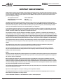
Outdoor Antenna Grounding—If an outside antenna or cable system is connected to these audio products, be sure
the antenna or cable system is grounded so as to provide some protection against voltage surges and built-up static charges. Section
810 of the U.S. National Electrical Code, and Section 54 of the Canadian Electrical Code, provide information with respect to proper
grounding of the mast and supporting structure, grounding of the lead-in wire to an antenna discharge unit, size of grounding conductors, location of antenna-discharge unit, connection to grounding electrodes, and requirements for the grounding electrode. See the
grounding diagram (right).
Overloading—Do not overload wall outlets and extension cords, as this could result in fire or electric shock.
Object and Liquid Entry —Never insert objects of any kind
through the openings of these appliances, as they may touch dangerous voltage points or short-out parts that could result in a fire or electric shock. Care
should be taken so that objects do not fall and liquids are not spilled into the
appliance through openings in the enclosure.
Grounding
Diagram
ANTENNA
LEAD-IN WIRE
Servicing—Do not attempt to service these appliances yourself, as opening or removing covers may expose you to dangerous voltage or other hazards. Refer all servicing to qualified service personnel.
GROUND
CLAMPS
ANTENNA LEAD-IN WIRE
(CEC SECTION 54-200)
(NEC SECTION 810-20)
ELECTRIC
SERVICE
EQUIPMENT
Damage Requiring Service—These appliances should be serviced by qualified service personnel when:
• A power supply connection or a plug has been damaged or
NEC - NATIONAL ELECTRICAL CODE
CEC - CANADIAN ELECTRICAL CODE
• If liquid has been spilled into the appliance or objects have fallen into
the appliance or
• The appliance has been exposed to water or moisture or
• The appliance does not appear to operate normally or exhibits a marked change in performance or
• The appliance has been dropped or the enclosure damaged.
GROUNDING CONDUCTORS
(CEC SECTION 54-200)
(NEC SECTION 810-21)
GROUND CLAMPS
POWER SERVICE GROUNDING
ELECTRODE SYSTEM
(CEC SECTION 10-700)
(NEC ARTICLE 250, PART H)
Replacement Parts—When replacement parts are required, be sure the service technician has used replacement parts
specified by the manufacturer or that have the same characteristics as the original part. Unauthorized substitutions may result in fire,
electric shock, or other hazards. The Master Control Unit battery should be replaced only after turning the power off and only by an
authorized installer.
Safety Check—Upon completion of any service or repairs to this audio product, ask the service technician to perform safety
checks to determine that the audio product is in proper operating condition.
Lightning—For added protection for these audio products during an electrical storm, or when they are left unattended and
unused for long periods of time, turn off the circuit breaker, and disconnect the antenna or cable system. This will prevent damage to
the audio products due to lightning and power-line surges.
©2004 Linear LLC. All Rights Reserved. 07/04.
Page 3
H560
INSTALLATION MANUAL
IMPORTANT USER INFORMATION
H560 has been registered with the Federal Communications Commission (FCC) in accordance with Parts 68 of its rules. On
the front panel of the H560 Music & Communications Distribution Amplifier is a label that contains, among other information,
the FCC registration number and ringer equivalence number (REN) for this equipment. If requested, this number must be
given to the telephone company.
FCC Registration Number:
Ringer Equivalence Number (REN):
Load Number (LN):
5J7USA-30852-MA-T
0.6B 1.1F
12B (Canada only)
The REN is useful in determining the quantity of devices you may connect to your telephone line and still have all those
devices ring when your number is called. In most, but not all areas, the sum of all RENs of all devices connected to one line
should not exceed five (5.0). To find out the number of devices you may connect to your line, as determined by the REN,
contact your local telephone company for the maximum REN for your calling area.
If your telephone equipment causes harm to the telephone network, the telephone company may discontinue your service
temporarily. If possible, they will notify you in advance. But, if advance notice isn’t practical, you will be notified as soon as
possible. You will be notified of your right to file a complaint with the FCC.
Your telephone company may make changes in its facilities, equipment, operations, or procedures that could affect the
proper functioning of your equipment. If they do, you will be notified in advance to give you an opportunity to maintain uninterrupted telephone service. If you experience trouble with this telephone equipment, please contact TECHNICAL SUPPORT
at 1-800-999-5225 for information on obtaining service or repairs. The telephone company may ask that you disconnect this
equipment from the network until the problem has been corrected or until you are sure the equipment is not malfunctioning.
If the telephone features are not functioning or are malfunctioning, switch off the circuit breaker connected to the system.
This will directly connect the telephone line with all the telephones connected to the package. Contact your dealer for
repairs.
This equipment may not be used on coin service provided by the telephone company. Connection of party lines is
subject to state tariffs. (Contact your state public utility commission for information).
This device complies with Part 15 of the FCC Rules. Operation is subject to the following conditions: (1) This device
may not cause harmful interference and (2) this device must accept any interference received, including interference
that may cause undesired operation.
Notice
The Industry Canada label identifies certified equipment. This certification means that the equipment meets certain telecommunications network protective, operational, and safety requirements. Industry Canada does not guarantee the equipment
will operate to the user’s satisfaction.
Before installing this equipment, users should ensure that it is permissible to be connected to the facilities of the local
telecommunications company. The equipment must also be installed using an acceptable method of connection. In some
cases, the company’s inside wiring associated with a single line individual service may be extended by means of a certified
connector assembly (telephone extension cord). The customer should be aware that compliance with the above conditions
may not prevent degradation of service in some situations.
The Load Number (LN) determines the number of devices you may connect to your line. The LN sum of all devices connected to one line shall not exceed 100.
Repairs to certified equipment can only be made by your local OpenHouse Installer.
This digital apparatus does not exceed the Class B limits for radio noise emissions from digital apparatus set out in the
Radio Interference Regulations of Industry Canada.
Contact TECHNICAL SUPPORT at 1-800-999-5225 for repairs to certified equipment.
Page 4
©2004 Linear LLC. All Rights Reserved. 07/04
H560
INSTALLATION MANUAL
Table of Contents
Safety Information............................................................... 2
System Overview..................................................................6
1. Distribution Center Installation.................................... 7
2. Audio Connections.......................................................... 9
3. Control Device Connections......................................... 14
4. Telephone and Door Station Connections...................20
5. Troubleshooting............................................................... 26
Warranty................................................................................ 35
Telephone Quick Reference..................................Back Page
©2004 Linear LLC. All Rights Reserved. 07/04.
Page 5
H560
INSTALLATION MANUAL
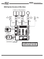
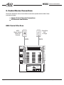
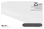
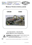
H560 System Overview & Wire Runs
In-Wall or In-Ceiling Speakers
H572
Stereo Volume
Controls w/
Override
H561
Music Input
Wall Plate
CAT5
CAT5
Door Station
(H580/H581)
CAT5
(Optional)
4 Conductor
Speaker Wire
H571
Mono Volume
Control w/
Override
(Optional)
CAT5
(Optional)
2131
In-Wall
IR Target
CAT5
2 Conductor
Speaker Wire
4 Conductor
Speaker Wire
4 TwistedPair Shielded
Wire w/ Drain
OR
Door Station w/
Color CCTV Camera
4 Twisted(H585)
Pair Shielded
Wire w/ Drain
Coax
Page 6
NOTICES:
THIS DEVICE COMPLIES WITH FCC PART 15 RULES AND
REGULATIONS. OPERATION IS SUBJECT TO THE
FOLLOWING TWO CONDITIONS: (1) THIS DEVICE MAY
NOT CAUSE HARMFUL INTERFERENCE AND (2) THIS
DEVICE MUST ACCEPT ANY INTERFERENCE THAT
MAY CAUSE UNDESIRED OPERATION.
THIS DIGITAL APPARATUS IS CERTIFIED TO COMPLY WITH
THE LIMITS OF A CLASS B DIGITAL DEVICE PURSUANT TO
PART 15 OF FCC RULES. SEE INSTRUCTION MANUAL IF
INTERFERENCE TO RADIO RECEPTION IS SUSPECTED.
COMPLIES WITH FCC PART 68
FCC REGISTRATION NUMBER: 5J7USA-30852-MA-T
RINGER EQUIVALENCE: 0.6B
PATENTS:
TENTS:
PA
5,130,893 5,327,144 5,131,048
MADE INCHINA P/N:930019592 REV A
To Video
Distribution
Module
Dedicated electrical circuit
(to be connected by a
licensed electrician only)
Multi-Room Audio & Intercom System
model H560
®
Linear LLC
Carlsbad, CA 92009, USA
www.openhousesystems.com
© 2004 Linear Corporation, Carlsbad, CA, USA
NO USER SERVICEABLE PARTS INSIDE.
REFER SERVICE TO OPEN HOUSE
APPROVED SERVICE TECHNICIAN.
Romex
CAT5 MUST BE RUN TO VOLUME
CONTROLS IF UTILIZING PAGE
AND/OR DOORBELL FEATURES!
©2004 Linear LLC. All Rights Reserved. 07/04
H560
INSTALLATION MANUAL
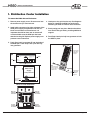
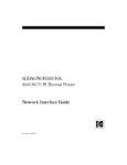
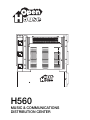
1. Distribution Center Installation
To mount the H560 into an Enclosure :
1. Remove power supply cover. Be sure not to lose
the screws once you remove them!
2. Install cable connectors into hole at bottom of the
H560 power supply compartment and into 3/4”
knock-out at bottom of the enclosure. It is
important that this be done now as access will
not be available once the H560 pan has been
attached to the grid. Replace power supply compartment cover when done.
4. Hook pan to the grid from the top. See diagrams
below for installing the H560 into enclosures.
Different grill holes are used for each enclosure.
5. Slowly swing pan into place. Metal nub and bottom hook fit into grid holes, providing additional
support.
6. Push Snap Latch pins fully into grommets to lock
the H560 in place.
3. Push ‘Snap Latch’ grommets (2) into the holes of
the H560 pan. Push ‘Snap Latch’ pins half-way
into grommets.
1
Nub fits into
grid hole for
additional
support
Multi-Room Audio & Intercom System
model H560
®
NOTICES:
THIS DEVICE COMPLIES WITH FCC PART 15 RULES AND
REGULATIONS. OPERATION IS SUBJECT TO THE
FOLLOWING TWO CONDITIONS: (1) THIS DEVICE MAY
NOT CAUSE HARMFUL INTERFERENCE AND (2) THIS
DEVICE MUST ACCEPT ANY INTERFERENCE THAT
MAY CAUSE UNDESIRED OPERATION.
THIS DIGITAL APPARATUS IS CERTIFIED TO COMPLY WITH
THE LIMITS OF A CLASS B DIGITAL DEVICE PURSUANT TO
PART 15 OF FCC RULES. SEE INSTRUCTION MANUAL IF
INTERFERENCE TO RADIO RECEPTION IS SUSPECTED.
COMPLIES WITH FCC PART 68
FCC REGISTRATION NUMBER: 5J7USA-30852-MA-T
RINGER EQUIVALENCE: 0.6B
PA
PATENTS:
TENTS:
5,130,893 5,327,144 5,131,048
MADE INCHINA P/N:930019592 REV A
Screw
4
Screw
Linear LLC
Carlsbad, CA 92009, USA
www.openhousesystems.com
NO USER SERVICEABLE PARTS INSIDE.
REFER SERVICE TO OPEN HOUSE
APPROVED SERVICE TECHNICIAN.
© 2004 Linear Corporation, Carlsbad, CA, USA
3
Power Supply Compartment
NOTE:
A second Snap Latch
needs to be inserted
on the other side of
the H560 as well
2
H560 Power
Supply
Compartment
5
Hook fits into
grid hole for
additional
support
Plastic Cable Connector
Use 3/4" Knockout
at bottom of
H318/H336 Enclosure
Metal Cable Connector
H318 or H336 Enclosure
25th grid
hole from
the bottom
25th grid
hole from
the bottom
Multi-Room Audio & Intercom System
model H560
®
4th grid
hole from
the bottom
NOTICES:
THIS DEVICE COMPLIES WITH FCC PART 15 RULES AND
REGULATIONS. OPERATION IS SUBJECT TO THE
FOLLOWING TWO CONDITIONS: (1) THIS DEVICE MAY
NOT CAUSE HARMFUL INTERFERENCE AND (2) THIS
DEVICE MUST ACCEPT ANY INTERFERENCE THAT
MAY CAUSE UNDESIRED OPERATION.
THIS DIGITAL APPARATUS IS CERTIFIED TO COMPLY WITH
THE LIMITS OF A CLASS B DIGITAL DEVICE PURSUANT TO
PART 15 OF FCC RULES. SEE INSTRUCTION MANUAL IF
INTERFERENCE TO RADIO RECEPTION IS SUSPECTED.
COMPLIES WITH FCC PART 68
FCC REGISTRATION NUMBER: 5J7USA-30852-MA-T
RINGER EQUIVALENCE: 0.6B
PATENTS:
TENTS:
PA
5,130,893 5,327,144 5,131,048
MADE INCHINA P/N:930019592 REV A
Linear LLC
Carlsbad, CA 92009, USA
www.openhousesystems.com
© 2004 Linear Corporation, Carlsbad, CA, USA
NO USER SERVICEABLE PARTS INSIDE.
REFER SERVICE TO OPEN HOUSE
APPROVED SERVICE TECHNICIAN.
©2004 Linear LLC. All Rights Reserved. 07/04.
4th grid
hole from
the bottom
Page 7
H560
INSTALLATION MANUAL
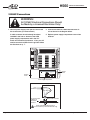
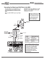
120VAC Connections
WARNING:
All 120VAC Electrical Connections Should
be Made by a Licensed Electrician Only!
1. Remove power supply cover (be sure not to lose
the screws once you remove them!)
A cable connector should already have been
installed in the hole at bottom of the H560
power supply compartment and in the 3/4”
knock-out at bottom of enclosure . If not, you will
need to remove the H560 from the grid and follow
the directions on p. 7.
2. Connect the H560 to a dedicated electrical circuit as shown in the diagram below.
3. Replace power supply compartment cover when
finished.
Multi-Room Audio & Intercom System
model H560
®
NOTICES:
THIS DEVICE COMPLIES WITH FCC PART 15 RULES AND
REGULATIONS. OPERATION IS SUBJECT TO THE
FOLLOWING TWO CONDITIONS: (1) THIS DEVICE MAY
NOT CAUSE HARMFUL INTERFERENCE AND (2) THIS
DEVICE MUST ACCEPT ANY INTERFERENCE THAT
MAY CAUSE UNDESIRED OPERATION.
THIS DIGITAL APPARATUS IS CERTIFIED TO COMPLY WITH
THE LIMITS OF A CLASS B DIGITAL DEVICE PURSUANT TO
PART 15 OF FCC RULES. SEE INSTRUCTION MANUAL IF
INTERFERENCE TO RADIO RECEPTION IS SUSPECTED.
COMPLIES WITH FCC PART 68
FCC REGISTRATION NUMBER: 5J7USA-30852-MA-T
RINGER EQUIVALENCE: 0.6B
PATENTS:
TENTS:
PA
5,130,893 5,327,144 5,131,048
MADE INCHINA P/N:930019592 REV A
Remove
Screw
Remove
Screw
Linear LLC
Carlsbad, CA 92009, USA
www.openhousesystems.com
© 2004 Linear Corporation, Carlsbad, CA, USA
NO USER SERVICEABLE PARTS INSIDE.
REFER SERVICE TO OPEN HOUSE
APPROVED SERVICE TECHNICIAN.
Power Supply Compartment
H560 Power Supply Compartment
From
Transformer
Green White Black
Use 3/4" Knockout
at Bottom of
H318/H336
Enclosure
Plastic Cable Connector
Metal Cable Connector
Romex to Dedicated Electrical Circuit
(To be connected by a licensed electrician only)
Page 8
©2004 Linear LLC. All Rights Reserved. 07/04
H560
INSTALLATION MANUAL
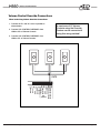
2. Audio Connections
This section details the audio connections necessary for proper installation of the H560.
These connections include:
Music Input Wall Plate (H561)
Volume Controls (H571/H572)
Speakers (Mono and/or Stereo)
In-Wall or In-Ceiling Speakers
H561
Music Input
Wall Plate
H571
Mono Volume
Control w/
Override
H572
Stereo Volume
Controls w/
Override
CAT5
(100' Max)
CAT5
CAT5
(Optional)
(Optional)
4 Conductor
Speaker Wire
CAT5
(Optional)
2 Conductor
Speaker Wire
4 Conductor
Speaker Wire
NOTE:
For wire runs less than
80 feet, use 16 or 18 GA
Twisted Pair for each
channel.
For wire runs longer than
80 feet, use 14 GA Twisted
Pair for each channel.
NOTICES:
THIS DEVICE COMPLIES WITH FCC PART 15 RULES AND
REGULATIONS. OPERATION IS SUBJECT TO THE
FOLLOWING TWO CONDITIONS: (1) THIS DEVICE MAY
NOT CAUSE HARMFUL INTERFERENCE AND (2) THIS
DEVICE MUST ACCEPT ANY INTERFERENCE THAT
MAY CAUSE UNDESIRED OPERATION.
THIS DIGITAL APPARATUS IS CERTIFIED TO COMPLY WITH
THE LIMITS OF A CLASS B DIGITAL DEVICE PURSUANT TO
PART 15 OF FCC RULES. SEE INSTRUCTION MANUAL IF
INTERFERENCE TO RADIO RECEPTION IS SUSPECTED.
COMPLIES WITH FCC PART 68
FCC REGISTRATION NUMBER: 5J7USA-30852-MA-T
RINGER EQUIVALENCE: 0.6B
PA
PATENTS:
TENTS:
5,130,893 5,327,144 5,131,048
MADE INCHINA P/N:930019592 REV A
Linear LLC
Carlsbad, CA 92009, USA
www.openhousesystems.com
© 2004 Linear Corporation, Carlsbad, CA, USA
©2004 Linear LLC. All Rights Reserved. 07/04.
Multi-Room Audio & Intercom System
model H560
®
NO USER SERVICEABLE PARTS INSIDE.
REFER SERVICE TO OPEN HOUSE
APPROVED SERVICE TECHNICIAN.
Page 9
H560
INSTALLATION MANUAL
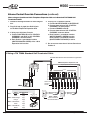
Connecting the Music Input Wall Plate to the H560
The H561 Music Input Wall Plate is an
in-wall preamp t h a t sends the audio
from the homeowner’s receiver to the
H560.
DO NOT Connect Speaker Level
Audio to the H560 as this will
damage the unit!
This is a LINE LEVEL input only (Tape
Out).
OpenHouse recommends the use
of a FIXED line level output (Tape
Out, for example) from the receiver so that music can be heard in
every room regardless of the
receiver’s volume setting.
INPUT Level
Adjustment
H561
Music Input
Wall Plate
Brown/Wh
Green/Wh
Orange/Wh
CAT5 Cable
Blue
Orange
Green
Blue/Wh
Brown
H560
H561 Wall Plate
+12 V
Blue +12V
SHLD/GND
Blue/Wh GND
-12 V
Orange -12V
AUDIO L
Green L
AUDIO R
Brown R
Ground Return Connections
Connect the Brown/Wh, Orange/Wh,
& Green/Wh to the SHLD/GND
terminal of the H560. The other
end of these conductors should
be twisted together and left
disconnected at the H561 Wall
Plate as shown.
Page 10
©2004 Linear LLC. All Rights Reserved. 07/04
H560
INSTALLATION MANUAL
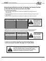
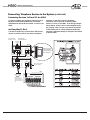
Determining the Maximum Amount of Speakers and Volume Controls
w/ Override That Can Be Connected to the H560.
The following tables assume:
1. One H572 Stereo Volume Control w/ Override at an impedance match setting of 8X per 8
ohm stereo pair.
2. One H571 Mono Volume Control w/ Override at an impedance match setting of 16X per 8 ohm
mono speaker.
3. All mono speakers are distributed evenly between the H560’s mono speaker connections.
Number of 8 Ohm Stereo Speaker
Pairs Connected to the H560
0
1
2
3
4
5
6
Maximum Number of 8 Ohm
Mono Speakers Allowed
24
20
16
12
8
4
0
Failure to comply with the
Maximum Speaker and
Override Volume Control
Specifications may cause
damage to the amplifier
and will VOID the manufacturer’s warranty.
Based on the same assumptions, the table below indicates the combinations of Stereo and
Mono speakers that can be connected to the H560 when using 4 or 6 Ohm speakers.
Number 4 or 6 Ohm Stereo Speaker
Pairs Connected to the H560
0
1
2
3
4
Maximum Number of 8 Ohm
MONO Speakers Allowed
12
9
6
3
0
All H572 Stereo Volume
Controls must be set to
8X Impedance Match.
All H571 Mono Volume
Controls must be set to
16X Impedance Match.
A maximum of 12 Volume Controls using the Override Feature
can be connected to the H560. See page 15 for further details.
The H560 is designed specifically for use with OpenHouse H571
and/or H572 Volume Controls w/ Override ONLY! Failure
to comply with this specification may cause damage to the
amplifier and will VOID the manufacturer’s warranty.
©2004 Linear LLC. All Rights Reserved. 07/04.
Page 11
H560
INSTALLATION MANUAL
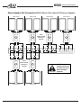
Stereo Speaker Pair Connections (MAX 6 Stereo Pairs rated at 8 Ohms per Speaker)
Stereo pair #1
Stereo pair #2
Stereo pair #4
Stereo pair #3
H572
Stereo Volume
Controls w/
Override
L
L
L
L
R
L
R
L
L
R
M
M
L
R
R
L
R
Page 12
L
SPEAKER OUTPUTS
R
H572
Stereo Volume
Controls w/
Override
Stereo pair #5
L
L
R
M
M
L
R
R
M
M
R
R
L
L
L
R
M
M
R
R
R
All H572 Stereo Volume
Controls must be set to
8X. Failure to do so can
result in damage to
equipment.
Stereo pair #6
©2004 Linear LLC. All Rights Reserved. 07/04
H560
INSTALLATION MANUAL
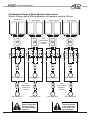
Combination Stereo & Mono Speaker Connections
Shown: 4 Stereo pair & 8 Mono speakers. All speakers rated at 8 Ohms.
Stereo pair #1
Stereo pair #2
Stereo pair #4
Stereo pair #3
H572
Stereo Volume
Controls w/
Override
L
L
L
R
M
M
R
L
L
L
R
Mono Speaker #2
R
M
M
R
R
Mono Speaker #3
Mono Speaker #4
All H572 Stereo Volume
Controls must be set to
8X. Failure to do so
can result in damage to
equipment.
©2004 Linear LLC. All Rights Reserved. 07/04.
L
L
SPEAKER OUTPUTS
H571
Stereo Volume
Controls w/
Override
Mono Speaker #1
L
R
M
M
R
R
Mono Speaker #5
L
L
L
R
M
M
R
R
Mono Speaker #7
H571
Stereo Volume
Controls w/
Override
Mono Speaker #6
Mono Speaker #8
All H571 Mono Volume
Controls must be set
to 16X. Failure to do
so can result in damage to equipment.
Page 13
H560
INSTALLATION MANUAL
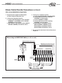
3. Control Device Connections
This section details the various Control Device connections possible with the H560. These
connections include:
Volume Control Override Connections
IR Receivers and Emitters
H560 Control Wire Runs
H572
Stereo Volume
Control w/
Override
ChannelPlus
2131
IR Target
CAT5
CAT5
Multi-Room Audio & Intercom System
model H560
®
NOTICES:
THIS DEVICE COMPLIES WITH FCC PART 15 RULES AND
REGULATIONS. OPERATION IS SUBJECT TO THE
FOLLOWING TWO CONDITIONS: (1) THIS DEVICE MAY
NOT CAUSE HARMFUL INTERFERENCE AND (2) THIS
DEVICE MUST ACCEPT ANY INTERFERENCE THAT
MAY CAUSE UNDESIRED OPERATION.
THIS DIGITAL APPARATUS IS CERTIFIED TO COMPLY WITH
THE LIMITS OF A CLASS B DIGITAL DEVICE PURSUANT TO
PART 15 OF FCC RULES. SEE INSTRUCTION MANUAL IF
INTERFERENCE TO RADIO RECEPTION IS SUSPECTED.
COMPLIES WITH FCC PART 68
FCC REGISTRATION NUMBER: 5J7USA-30852-MA-T
RINGER EQUIVALENCE: 0.6B
PA
PATENTS:
TENTS:
5,130,893 5,327,144 5,131,048
MADE INCHINA P/N:930019592 REV A
Linear LLC
Carlsbad, CA 92009, USA
www.openhousesystems.com
© 2004 Linear Corporation, Carlsbad, CA, USA
Page 14
NO USER SERVICEABLE PARTS INSIDE.
REFER SERVICE TO OPEN HOUSE
APPROVED SERVICE TECHNICIAN.
©2004 Linear LLC. All Rights Reserved. 07/04
H560
INSTALLATION MANUAL
Volume Control Override Connections
When hard wiring Volume Override Connections:
1. Connect all VC+ and VC- wires in parallel as
shown below.
A maximum of 12 Volume
Controls using the Override
Feature can be connected if
using this wiring method!
2. Connect VOL CONTROL OVERRIDE+ from
H560 to VC+ of Volume Controls.
3. Connect VOL CONTROL OVERRIDE- from
H560 to VC- of Volume Controls.
VC+
VC-
VC+
VC-
VC+
VC-
CAT5
AUX
CON TROL
©2004 Linear LLC. All Rights Reserved. 07/04.
VOL CON T OV ERRIDE +
VOL CON T OV ERRIDE -
IR +12V
GND
IR RECEIVE
IR SEND
P+DB CON T
MUTE CON T
GND
P+DB A UDIO
MUTE LED
0+ 0-
Page 15
H560
INSTALLATION MANUAL
Volume Control Override Connections (continued)
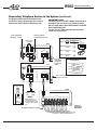
When using an OpenHouse H618 Telephone Expansion Hub and a Standard TIA T568A SelfTerminated Cable:
1. Reference the diagram below for PIN configuration.
2. Plug RJ45 end of pigtail into RJ45 IN jack
on the H618 Telephone Expansion Hub.
3. If wiring up to 8 Volume Controls:
a. Connect WHITE/BLUE to VOL CONTROL
OVERRIDE+ and BLUE to VOL CONTROL
OVERRIDE- as shown below.
b. Each Position 1 punchdown location
(WHITE/ORANGE & GREEN) of the H618
Expansion Hub is active.
4. If wiring 9 to 12 Volume Controls:
a. Connect WHITE/ORANGE to WHITE/BLUE.
b. Connect these wires to VOL CONTROL
OVERRIDE+ as shown below.
c. Connect ORANGE to BLUE.
d. Connect these wires to VOL CONTROL
OVERRIDE- as shown below.
e. Each Position 1 punchdown location
WHITE/ORANGE & GREEN) is active.
Each Position 2 punchdown location
(WHITE/GREEN & ORANGE) is active.
5. Do not connect more than 4 Volume Controls on
Position 2.
If Using a TIA T568A Standard Self-Terminated Cable
TIA T568A Standard Self-Terminated RJ45 to Pigtail Cable
White/Blue
Blue
White/Orange
Orange
White/Green
Green
White/Brown
Brown
H618 Telephone Expansion Hub
Telephone Expansion Hub (4 lines x 8 phones)
ChannelPlus model H618
Expansion
Ports
Telephones
R
4
T
In
In
R
3
T
R
2
T
Out
Out
R
1
T
CAT5 to Volume
Controls w/
Override
H560
RJ-45 Wired to TIA T568A Standard
Pair 1
RJ-45 Position
Color
5 (T)
White/Blue
4 (R)
Blue
Pair 2 White/Orange
Orange
3 (T)
6 (R)
Pair 3 White/Green
Green
1 (T)
2 (R)
Pair 4 White/Brown
Brown
7 (T)
8 (R)
Page 16
PR2
PR3 PR1 PR4
T RT RT RT R
12 3 45 67 8
VC+ (White/Orange)
VC- (Green)
VC+ (White/Green)
VC- (Orange)
H571 or H572
Volume Controls
w/ Override ONLY!
©2004 Linear LLC. All Rights Reserved. 07/04
H560
INSTALLATION MANUAL
Volume Control Override Connections (continued)
When using an H693 RJ45 to Pigtail Cable:
1. Plug RJ45 end of pigtail into RJ45 IN jack
on H618 Telephone Expansion Hub.
2. If wiring up to 8 Volume Controls:
a. Connect WHITE/ORANGE to VOL CONTROL
OVERRIDE + and GREEN to VOL CONTROL
OVERRIDE as shown below.
b. Each Position 1 punchdown location (WHITE/
ORANGE & GREEN) of the H618 is active.
3. If wiring 9 to 12 Volume Controls:
a. Connect WHITE/ORANGE to WHITE/GREEN.
b. Connect these wires to VOL CONTROL
OVERRIDE+ as shown below.
c. Connect ORANGE to GREEN.
d. Connect these wires to VOL CONTROL
OVERRIDE- as shown below.
e. Each Position 1 punchdown location
WHITE/ORANGE & GREEN) is active.
Each Position 2 punchdown location
(WHITE/GREEN & ORANGE) is active.
4. Do not connect more than 4 Volume Controls on
Position 2.
When using an H693 RJ45 Cable (cut off one end)
H693 RJ45 Cable w/ End Cut Off
Blue
White/Blue
Orange
White/Orange
Green
White/Green
Brown
White/Brown
H618 Telephone Expansion Hub
Telephone Expansion Hub (4 lines x 8 phones)
ChannelPlus model H618
Telephones
Expansion
Expansion
Ports
Ports
J8
110D-4
J7
110D-4
J6
110D-4
J5
110D-4
J3
110D-4
J4
110D-4
J2
110D-4
J1
110D-4
R
4
T
J10
In
In
R
3
T
RJ-4
5
J9
R
2
T
Out
Ou t
Bl
u
Bl
u
Blu
Bl
u
Bl
u
Blu
Bl
u
Bl
u
R
1
T
CAT5 to Volume
Controls w/
Override
H560
VC+ (White/Orange)
VC- (Green)
VC+ (White/Green)
VC- (Orange)
H571 or H572
Volume Controls
w/ Override ONLY!
©2004 Linear LLC. All Rights Reserved. 07/04.
Page 17
H560
INSTALLATION MANUAL
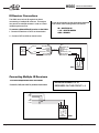
IR Receiver Connections
The H560 has a built-in IR engine that allows
connectivity of multiple IR receivers. This engine
can pass IR to multiple emitters in order to control
multiple system sources.
It may be convenient to use OpenHouse standard
color codes when making these connections:
IR = WHITE/BLUE
+12V = WHITE/GREEN
GND = BROWN
To connect a ChannelPlus IR receiver to the H560:
1. Connect IR Receiver to CAT5 as shown below.
2. Connect CAT5 to H560 as shown below.
Connecting an IR Receiver
IR Send
Channel
Plus 2131
IR
Receiver
+12V
GND
Blue
White/Blue (IR)
Orange
White/Orange
Green
White/Green (+12V)
Brown (GND)
White/Brown
Blue
White/Blue (IR)
Orange
White/Orange
Green
White/Green (+12V)
Brown (GND)
White/Brown
CAT-5
H560
IR SEND
GND
IR RECVE
IR +12V
i+ g ir is
TO IR
ACCESSORIES
Connecting Multiple IR Receivers
To connect multiple IR Receivers to the H560:
Connect IR, GND, and 12VDC in parallel as shown below.
MAXIMUM NUMBER OF IR
RECEIVERS ON THIS CIRCUIT = 4
IR
GND
+12V
IR
GND
+12V
IR RECVE
IR SEND
IR +12V
GND
i+ g ir is
TO IR
ACCESSORIES
Page 18
H560
©2004 Linear LLC. All Rights Reserved. 07/04
H560
INSTALLATION MANUAL
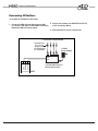
Connecting IR Emitters
To connect IR Emitters to the H560:
1. Connect IR SEND (is) and GND from the H560
to a Xantech 789-44PS or ELAN IRD4 Powered IR
Distribution Block as shown below.
2. Plug IR mini-emitters into EMITTER OUTPUTS
of the Connecting Block.
3. Attach Emitters to source components.
To Source Components
Channel Plus
2171, 2172,
and/or 2173
12V IR Emitters
(or equivalent)
+12VDC
Power Supply
Emitter Outputs
GND
IR IN
Xantech 789-44PS
or ELAN IRD4 Powered
IR Distribution Block
IR SEND
IR RECEIVE
GND
IR +12V
i+ g ir is
TO IR ACCESSORIES
H560
©2004 Linear LLC. All Rights Reserved. 07/04.
Page 19
H560
INSTALLATION MANUAL
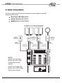
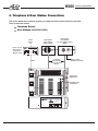
4. Telephone & Door Station Connections
This section details the procedures necessary to enable the Communication features of the H560.
These connections include:
Telephone Service
Door Stations (H580/H581/H585)
TelCo
Service
IN
Open House
Model H611
Telephone
Master Hub
Open House
Door Station
w/ Color CCTV Camera
(H585)
Open House
Door Station
(H580 or H581)
Telephone M aster Hub (Surge
, RJ-31X
, Disconnect
)
Channel Plus model H611
From
Telco
Disconnect
In
Ou t
Surg
e
Wa rnin
g
-OR-
Telephone
Output
RJ31X
4 TwistedPair Shielded
Wire w/ Ground
Return
CAT5
Coax to video
distribution module
Page Level
Adjustment
Doorbell Level
Adjustment
Multi-Room Audio & Intercom System
model H560
®
NOTICES:
THIS DEVICE COMPLIES WITH FCC PART 15 RULES AND
REGULATIONS. OPERATION IS SUBJECT TO THE
FOLLOWING TWO CONDITIONS: (1) THIS DEVICE MAY
NOT CAUSE HARMFUL INTERFERENCE AND (2) THIS
DEVICE MUST ACCEPT ANY INTERFERENCE THAT
MAY CAUSE UNDESIRED OPERATION.
THIS DIGITAL APPARATUS IS CERTIFIED TO COMPLY WITH
THE LIMITS OF A CLASS B DIGITAL DEVICE PURSUANT TO
PART 15 OF FCC RULES. SEE INSTRUCTION MANUAL IF
INTERFERENCE TO RADIO RECEPTION IS SUSPECTED.
COMPLIES WITH FCC PART 68
FCC REGISTRATION NUMBER: 5J7USA-30852-MA-T
RINGER EQUIVALENCE: 0.6B
PA
PATENTS:
TENTS:
5,130,893 5,327,144 5,131,048
MADE INCHINA P/N:930019592 REV A
Linear LLC
Carlsbad, CA 92009, USA
www.openhousesystems.com
© 2004 Linear Corporation, Carlsbad, CA, USA
Page 20
NO USER SERVICEABLE PARTS INSIDE.
REFER SERVICE TO OPEN HOUSE
APPROVED SERVICE TECHNICIAN.
©2004 Linear LLC. All Rights Reserved. 07/04
H560
INSTALLATION MANUAL
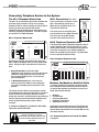
Connecting Telephone Service to the System
The H611 Telephone Master Hub
The H611 is an OpenHouse grid-mount module that
provides surge protection for up to 4 incoming
telephone lines as well as offering an RJ31X jack for
security systems and a Quick Disconnect.
Telephone Outputs (RJ45 and 110 punchdown) provide easy expansion capabilities. The H611’s jacks
are wired to TIA T568A standard.
H611 Telephone Master Hub
Telephone Master Hub (Surge, RJ-31X, Disconnect)
ChannelPlus model 611
From
Telco
In
Disconnect
Out
Surge
Warning
Telephone
Output
R
4
T
R
3
T
R
2
T
RJ31X
R
1
T
RJ31X
OpenHouse strongly recommends the use of two
H611 Telephone Master Hubs for every H560 installation. Using two H611s provides the homeowner
with:
H611 Connections The “From
Telco” punchdown connector on the
H611 automatically routes Line 1
(Blue pair) to the RJ31X jack. This
would be the H560 line.
The reason that two H611s are required to obtain
these safeguards is that the RJ31X jack on the H611
is wired in front of the surge protection circuitry.
Using only one H611 would provide surge protection
only on Phone IN and would disable telephone service if the Quick Disconnect jumper cable is
removed.
IF THERE IS A SECURITY SYSTEM IN THE HOME,
TWO H611s MUST BE USED.
Whether it's an OpenHouse H611 or
another manufacturer's device,
TELEPHONE LINE SURGE PROTECTION
SHOULD ALWAYS BE INSTALLED ON
THE H560.
©2004 Linear LLC. All Rights Reserved. 07/04.
H560
Phone IN
H560
Phone OUT
H618 Telephone Expansion Hub
The OpenHouse H618 Telephone Expansion Hub is
used to distribute the surge-protected C.O. Lines
coming from the H611 to 8 telephone wall plates. If
more than 8 extensions are needed, additional
H618s can be added to the system. The Expansion
Ports on the H618 make this easy.
H618 Telephone Expansion Hub
Telephone Expansion Hub (4 lines x 8 phones)
ChannelPlus model H618
Surge Protection on both the H560
Telephone Input & Output. This helps protect the
H560 from surge ingress that can come from
the incoming telephone line or from the tele
phone extensions.
A Quick Disconnect that, in the event of
failure,removes the H560 from the telephone
loop without disabling the homeowner’s telephones.
12345678
The center pins on the RJ31X jack
are connected to the H560 Phone IN.
The outer pins of the RJ31X jack
connect to the H560 Phone OUT.
Telephones
Expansion
Ports
H560 to RJ31X
RJ-45 Pin Out
RJ-45
J10
J8
110D-4
J7
110D-4
J6
110D-4
J5
110D-4
J3
110D-4
J4
110D-4
J2
110D-4
J1
110D-4
In
R
4
T
R
3
T
R
2
T
RJ-45
J9
Out
Blu
Blu
Blu
Blu
Blu
Blu
Blu
Blu
R
1
T
Modems, Fax Machines, Satellite & Cable
To ensure problem-free operation, any device other
than a telephone that uses the phone line to dial out
or receive data should be connected ‘in front of’ the
H560. Such devices include:
Modems
Fax Machines
Answering Machines
Satellite & Cable Boxes
Digital Music Servers
OpenHouse recommends the use of Dual Telephone
Wall Plates with the top jack wired for telephone use
and the bottom jack wired in front of the H560 for use
with these devices
See “Connecting Devices In Front Of The H560”
on page 23.
Page 21
H560
INSTALLATION MANUAL
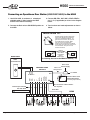
Connecting Telephone Service to the System (continued)
The diagram below shows telephone service
connections using 2 OpenHouse H611s and an
OpenHouse H618 Telephone Expansion Hub.
IMPORTANT NOTE:
The RJ-45 jacks on the H611 Master Hub and H618
Expansion Hub are wired to TIA T568A standard.
DO NOT USE H693 RJ45 INTERCONNECT CABLES
WITH THESE DEVICES.
The pin-outs for T568A standard self-terminated
cables are shown below.
Security System
Connection (RJ-31X)
From Telephone
Company - 4 lines
RJ-45 wired to TIA T568A
Color RJ-45 Position
Pair 1 White/Blue
5 (T)
PR3
4 (R)
Blue
CAT-5 Jumper
(Included)
H611
Telephone Master Hub (Surge, RJ-31X, Disconnect)
ChannelPlus model H611
From
Telco
In
Disconnect
Out
Telephone
Output
Surge
Warning
R
4
T
R
3
T
R
2
T
R
1
T
RJ31X
Pair 2 White/Orange
Orange
3 (T)
6 (R)
Pair 3 White/Green
Green
1 (T)
2 (R)
Pair 4 White/Brown
Brown
7 (T)
8 (R)
See p. 23
“Connecting
Devices In
Front of the
H560"
H611
In
Disconnect
Out
Telephone
Output
Surge
Warning
R
4
T
R
3
T
R
2
T
R
1
T
RJ31X
}
T RT RT RT R
12345678
Telephone Line Connections
to the H611
{ Brown
Brown/White
Green
Line 3 {
Green/White
Orange
Line 2 {
Orange/White
Blue
Line 1 {
Blue/White
Line 4
Telephone Master Hub (Surge, RJ-31X, Disconnect)
ChannelPlus model H611
From
Telco
PR2
PR1 PR4
R
T
R
T
R
T
R
T
4
3
2
1
Can be used for additional
telephone wall plates
H560 to RJ31X
RJ-45 Pin Out
H618
12345678
H560
Phone IN
H560
Phone OUT
Phone
IN
Telephone Expansion Hub (4 lines x 8 phones)
ChannelPlus model H618
Phone
OUT
Expansion
Expansion
Ports
Ports
H560
BLUE pair (Line 1) is
automatically routed
through the RJ31X jack.
This is the ‘Open House’
line.
In
In
Telephones
J8
110D-4
J7
110D-4
J6
110D-4
J5
110D-4
J3
110D-4
J4
110D-4
J2
110D-4
J1
110D-4
R
4
T
R
3
T
Out
Out
To additional H618 if needed
Page 22
J10
R
2
T
RJ-45
J9
Blu
Blu
Blu
Blu
Blu
Blu
Blu
Blu
R
1
T
4 lines to
8 telephone
Wall plates
©2004 Linear LLC. All Rights Reserved. 07/04
H560
INSTALLATION MANUAL
Connecting Telephone Service to the System (continued)
Connecting Devices ‘In Front Of’ the H560
To ensure problem-free operation, devices such as
Modems, Fax/Answering Machines and Cable/
Satellite boxes should be connected ‘in front of’ the
H560.
An Easy Way To Do It
The H611 accepts up to 4 phone lines. Since most
homes do not have 4 lines, the extra punchdown
positions on the H611 Output Punchdown
Connector can be used for connecting these
devices ‘in front of’ the H560. In the wiring example
shown below, Line 4 is not an active telephone line.
By ‘jumping’ Line 1 to Line 4 any device connected
to the bottom jack of a Dual Telephone Wall Plate
would be connected directly to the phone line before
it hits the H560.
Security System
Connection (RJ-31X)
From Telephone
Company- 4 Lines
CAT5 Jumper
(Included)
H611 #1
Telephone Master Hub (Surge, RJ-31X, Disconnect)
ChannelPlus model H611
From
Telco
In
Disconnect
Out
R
T
R
T
R
T
R
T
Telephone
Output
Surge
Warning
R
4
T
R
3
T
R
2
T
R
1
T
RJ31X
4
Jump Line 1 R & T
to an unused line
(Line 4 shown here
as an example)
3
2
1
H611 #2
Telephone Master Hub (Surge, RJ-31X, Disconnect)
ChannelPlus model H611
From
Telco
In
Disconnect
Out
Telephone
Output
Surge
Warning
R
4
T
R
3
T
R
2
T
R
1
T
RJ31X
}
Can be used for additional
telephone wall plates
H618
Phone
IN
Telephone Expansion Hub (4 lines x 8 phones)
ChannelPlus model H618
Phone
OUT
Expansion
Expansion
Ports
Ports
H560
BLUE pair (Line 1) is
automatically routed
through the RJ31X jack.
This is the ‘OpenHouse’
line.
In
In
Telephones
J8
J7
J6
110D-4
J10
J5
J3
110D-4
J4
J2
110D-4
J1
R
4
T
R
3
T
Out
Out
RJ-45
J9
R
2
T
Blu
Blu
©2004 Linear LLC. All Rights Reserved. 07/04.
Blu
Blu
Blu
Blu
Blu
Blu
R
1
T
Page 23
H560
INSTALLATION MANUAL
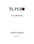
Connecting an OpenHouse Door Station (H580/H581/H585) to the H560
1. Use 22/24 AWG , 8 conductor, 4 twisted pair
shielded cable w/ drain between the H560
and the Door Station location(s).
3. Connect DB-/DB+, MIC-/MIC+, SPKR-/SPKR+,
and L-/L+ (if applicable) as shown in the diagram
below.
2. Connect the Drain wire to SHLD/GND position on
the H560.
4. Test functions and make adjustments as shown
below.
INSTALLATION TIP:
The Door Speaker and Door Microphone
levels can be adjusted by repositioning
2 shunts on the H560's PC Board . To
gain access to the shunts, the top cover
of the H560 must be removed. Make
sure you are fully grounded before
removing cover or touching the PC Board.
A wrist strap connected to an earth ground
is recommended. See p. 26 for cover
removal instructions.
DOOR SPEAKER
Lo
Hi
H585 ONLY
Default
shunt position
is Hi. Move
to opposite
pins to
lower levels.
DOOR MICROPHONE
MIC
Gain
J2
Lo
Hi
See Gaining Access to the H560 PC Board, p. 26.
H585
Doorbell Button
Door Latch
Power Supply
DB-
DB+
H580/H581/H585
PC Board
=Maintain Twisted Pair
SPKR-
SPKR+
MIC-
MIC+
L-
L+
DB-
DB+
4 twisted-pair shielded
wire with drain
Class 2 Low
Voltage Output
COM
N.O.
To Button
Page 24
J4
DSPK
Gain
to 110VAC
Electronic Door Latch
Release Mechanism
(not sold by Open House)
X
No connection at Door Station.
Cut at jacket.
Drain Wire
H560
©2004 Linear LLC. All Rights Reserved. 07/04
H560
INSTALLATION MANUAL
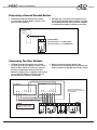
Connecting a Second Doorbell Button
1. The H560 provides two distinct door chimes:
a 3-note chime for Door Station 1 and a 2-note
chime for Door Station 2.
2. Although only 2 conductors are required to con
nect a second doorbell button, using a 4 twistedpair shielded wire with drain permits an upgrade
to a second Door Station if desired in the future.
Lighted
Doorbell
Button
Connections:
Doorbell Button + to DB2+ (d2)
Doorbell Button - to COMMON (c)
Connecting Two Door Stations
1. The H560 provides two distinct door chimes:
A 3-note chime for Door Station 1 and a 2-note
chime for Door Station 2. It does not, however,
provide for independent access to the Door
Stations. Pressing #,3 on a telephone will connect
you to both Door Stations. Pressing #,3,0 will
activate both door latches (if connected).
SPKR+
SPKR-
MIC+
MIC-
L+
L-
DB+
DB-
SPKR+
SPKR-
MIC+
MIC-
L+
Door Station 1
L-
DB+
DB-
Door Station 2
2. When connecting two Door Stations the
Doorbell, Latch and Microphone connections are
wired in parallel; the Speakers are wired in series.
Ground Return Wires from
Both Wire Runs. No connection
at Door Stations
H560
NOTE:
L & MIC are wired in parallel.
SPKRs are wired in series.
©2004 Linear LLC. All Rights Reserved. 07/04.
Page 25
H560
INSTALLATION MANUAL
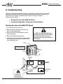
5. Troubleshooting
This section details the procedures necessary to troubleshoot problems that may arise when
installing or operating the H560. After following these procedures to their conclusion, call
Open House Tech Support at (800-999-5225) if unable to remedy the situation.
These procedures include:
Gaining Access to the H560 PC Board
Troubleshooting Audio, Telephone and Door Station
Gaining Access to the H560 PC Board
1. Turn off the AC power to the unit.
2. Remove the screw located to the right of the
two Line Level Output jacks.
3. Remove the four screws located on the front
cover of the H560.
You MUST be fully grounded before
accessing the H560 PC Board. Open
House recommends the use of a
grounding wrist strap anchored to an
earth ground.
4. Remove both Multi-Pin Connectors.
5. Carefully ease off the H560’s cover from the bottom, making sure not to bend or break the Line
Level Output RCA Jack.
Remove
Connectors
NOTE:
Connectors MUST be Removed
in Order to Remove Front Plate.
Remove
Screws
Remove
Screws
Door Speaker
Configuration
Jumper
J4
LO HI
DSPK
GAIN
J19
MUTE SW
No SW
MUTE
Config.
MIC LO
GAIN
EPROM
HI
J2
DO NOT
ADJUST!
Door Microphone
Configurations
Jumper
DO NOT REMOVE OR
DISCONNECT while
system is powered up,
as this will cause severe
damage to the H560.
Page 26
©2004 Linear LLC. All Rights Reserved. 07/04
H560
INSTALLATION MANUAL
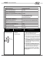
H560 Audio Distribution Amplifier Reference Voltages
Between H560 Pins:
Voltage Should Read:
+12V (+) and SHLD/GND (G)
+12 VDC
-12V (-) and SHLD/GND (G)
-12 VDC
PHONE OUT TIP (to) and PHONE OUT RING (ro)
+24 VDC
VOL CONT OVERRIDE+ (O+) and VOL CONT
12 VDC between O+ and Oonly when Page/DB is active
O+ will always read +12 VDC
to any Ground except O-
DB1+(d1) or DB2+ (d2)
and DOORBELL COMMON (C)
+12 VDC
LATCH+ (l+) and LATCH- (l-)
+12 VDC only when #,3,0 is pressed and held
MIC+ (m+) and MIC- (m-)
+5 VDC
SPEAKER+ (s+) AND SPEAKER- (s-)
0 VDC
IR+12V (I+) and GND (g)
+12 VDC
MUTE SW+ (S) and SHLD/GND (G)
+4.75 VDC
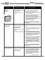
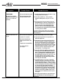
Symptom
Possible Cause
No music
(doorchime & page ok)
• Mis-wired Music Input
Wallplate.
• Fuses are blown.
Possible Solution
1. Confirm that the audio source and the RCA
patch cord between audio source & the
Music Input Wallplate are good.
2. Be sure that Volume Controls are turned up
3. Confirm that the Input Level Adjustment pot
on the Music Input Wallplate is turned up.
Volume
Level
Adjustment
4. Check for +/- 12 VDC present at the Music
Input Wallplate and verify L & R audio wires
are connected properly. If not, check the
fuses with a meter. Replace with 4A slow
blow fuses only.
5. Cycle power to the H560 by going to the
main electrical circuit panel and turning the
appropriate breaker off, waiting 30 seconds, then turning the breaker back on.
If, after trying all of the above, the problem
persists, call OpenHouse Technical Support
for assistance.
©2004 Linear LLC. All Rights Reserved. 07/04.
Page 27
H560
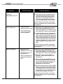
Symptom
Possible Cause
• Bad, stuck or mis-wired
Doorbell button
AUDIO
No Doorbell
• Doorbell level turned
down
INSTALLATION MANUAL
Possible Solution
1. Be sure that Volume Controls are turned up.
2. Be sure that the Doorbell Volume
Adjustment pot on the front of the H560 is
turned up (clockwise).
3. With a piece of wire, paper clip, etc., short
together the doorbell pins (DB+ and
Common) on the H560. This bypasses any
potential wiring or doorbell button problems. If the music mutes and the
doorchime is heard, you may have a faulty
doorbell button or wiring.
Page Level
Adjustment
Doorbell
Level
Adjustment
If, after trying all of the above, the problem
persists, call OpenHouse Technical Support
for assistance.
No Paging Audio
(music is ok)
• Mis-wired telephone jack
• Mis-wired Override
Volume Control
• Not using touch-tone telephone
• Telephone incompatibility
1. Be sure that all Volume Controls are turned
up.
2. Be sure that the Page Volume Adjustment
pot on the front of the H560 is turned up
(clockwise).
3. Confirm that Paging Audio is not being
heard in all rooms and from all telephones.
If this is not the case, you may have a miswired telephone jack, a faulty or incompatible telephone, or a mis-wired Volume
Control w/ Override.
4. Verify that you are getting the System Dial
Tone and press #,7 to page. If still unsuccessful, connect a single-line, corded,
touch-tone telephone or butt set directly to
the H560 Phone Out pins (“to” and “ro”)
and try paging again. This bypasses any
potential wiring problem occurring after the
H560.
If, after trying all of the above, the problem
persists, call OpenHouse Technical Support
for assistance.
Paging audio drops out
• Page volume set too high
• Mis-wired Override
Volume Control
1. Turn down the Page Volume Adjustment
pot on the front of the H560 to a very low
level (counter clockwise). Confirm that
page no longer drops out, and slowly
increase the level (clockwise) until you
reach an acceptable volume without the
page dropping out.
continued next page.....
Page 28
©2004 Linear LLC. All Rights Reserved. 07/04
H560
INSTALLATION MANUAL
Symptom
Possible Cause
Possible Solution
2. If page still drops out, check the VC+/VCconnections at all Volume Controls that
have the Override feature (a process of
elimination; i.e. removing the VC+/VCwires from each Volume Control one by
one, may quickly lead you to the culprit).
continued....
Paging audio drops out
If, after trying all of the above, the problem
persists, call OpenHouse Technical Support
for assistance.
Music is distorting
• H561 Music Input
Wallplate level is too high
• One or more Volume
Controls may be miswired or defective
1. Make sure you are feeding only a line level
audio output (not speaker level!) to the
Music Input Wallplate. Turn down the input
level adjustment on Music Input Wallplate.
2. If music still distorts, one or more volume
controls may be mis-wired or defective. To
verify, remove all volume controls from the
H560. Using an ohm meter on the disconnected wires coming back from the volume
control to the H560, check to see that the
impedance between the L+ and L-, and R+
and R- of all pairs of wires equals 6 to 9
ohms.
If, after trying all of the above, the problem
persists, call OpenHouse Technical Support
for assistance.
Music is cutting out
• H561 Music Input
Wallplate level is too high
• Mute Switch jumpers in
wrong position
• H560 is overloaded and
going into thermal shutdown
1. Make sure you are feeding only a line level
audio output (not speaker level!) to the
Music Input Wallplate. Turn down the input
level adjustment on Music Input Wallplate.
2. Mute Switch Jumpers should NOT be
changed. Jumper should remain in “No
SW” position.
3. Be sure you have not exceeded the maximum recommended speaker and volume
control limits outlined in this manual. Be
sure you are using only the specified
OpenHouse Volume Controls.
4. Remove all volume controls from the H560.
Using an ohm meter on the disconnected
wires coming back from the volume control
to the H560, check to see that the impedance between L+ and L-, and R+ and R- of
all pairs of wires equals 6 to 9 ohms.
If, after trying all of the above, the problem
persists, call OpenHouse Technical Support
for assistance.
©2004 Linear LLC. All Rights Reserved. 07/04.
Page 29
H560
Symptom
Possible Cause
TELEPHONE
• Mis-wired telephone jacks
No Dial Tone (neither
OpenHouse system dial
tone or C.O. dial tone
present)
• Mis-wire between H560
and punchdown block
INSTALLATION MANUAL
Possible Solution
1. Confirm that dial tone is not present on any
of the phones in the house.
2. Verify that +24VDC (+/- 4V) is present
between H560 phone out pins “to” and
“ro”.
3. Disconnect the incoming phone line from
the H560 (pins “ti” and “ri”). Connect a single-line, corded, touch-tone telephone or
butt set directly to the H560 Phone Out
pins (“to” and “ro”) and try paging again.
This bypasses any potential wiring problem
occurring after the H560.
If, after trying all of the above, the problem
persists, call OpenHouse Technical Support
for assistance.
Unable to dial out or no
ring in
• Non touch-tone telephone
1. Verify that phone(s) is not set on “pulse”.
• Inactive C.O. service
2. Verify that the problem is not specific to a
particular telephone.
• Mis-wired OpenHouse
phone inputs and/or outputs
• Telephone incompatibility
• Too many phones
(no ring in)
3. Verify that C.O. service is active (if an RJ-31
jack was installed), unplug the OpenHouse
line and connect a phone or butt set directly
to the jack. If no RJ-31 jack was installed,
disconnect the incoming phone line from the
OpenHouse Phone In pins (“ti” and “ri”) and
connect a phone or butt set directly to the
incoming line). Try dialing out/in.
4. Once C.O. Service is verified, reconnect the
incoming line to the H560 Phone In pins (“ti”
and “ri”), then connect a single-line, corded,
touch-tone telephone or butt set directly to
the H560 Phone Out pins (“to” and “ro”), verify system dial tone and try dialing out/in.
This bypasses any potential wiring problem
occurring after the H560.
5. A possible cause of ‘no ring in’ is that the
number of phones in the house has exceeded the Ringer Equivalency voltage provided
by the telephone company. To verify, unplug
all but one telephone and have someone dial
in. If the phone rings, check the Ringer
Equivalency Number (REN) of all the phones
in house (the FCC requires that this number
be listed on all telephones). If the total REN
exceeds 5.0 (including a REN of 0.6 for the
YHN system), this may be the cause of your
‘no ring in’.
If, after trying all of the above, the problem persists, call OpenHouse Technical Support for
assistance.
Page 30
©2004 Linear LLC. All Rights Reserved. 07/04
H560
INSTALLATION MANUAL
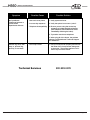
Symptom
No OpenHouse
Telephone features or
cannot break
OpenHouse dial tone
Possible Cause
Possible Solution
• Non touch-tone phone
1. Verify system dial tone.
• Incorrect key sequence
2. Verify that phone is not set to “pulse”.
• Telephone incompatibility
3. Be sure you are using the correct key
sequence to initiate the desired feature
(see Telephone Quick Reference Guide
immediately following the index).
4. Try another touch-tone telephone.
If, after trying all of the above, the problem
persists, call OpenHouse Technical Support
for assistance.
Phones ring once, then
stop, or, phones ring,
pick up, no one there
• Low Loop Current
Technical Services
©2004 Linear LLC. All Rights Reserved. 07/04.
1. Call your local phone company and find out
the value of the ‘Loop Current’ being sent
to the home. The system requires a minimum Loop Current of 18mA
800-999-5225
Page 31
H560
INSTALLATION MANUAL
NOTES:
Page 32
©2004 Linear LLC. All Rights Reserved. 07/04
H560
INSTALLATION MANUAL
NOTES:
©2004 Linear LLC. All Rights Reserved. 07/04.
Page 33
H560
INSTALLATION MANUAL
NOTES:
Page 34
©2004 Linear LLC. All Rights Reserved. 07/04
H560
INSTALLATION MANUAL
Limited Warranty
Linear LLC warrants this product to be free from defects in material and workmanship for 2 years.
The time period will be measured using the date code labeled on the product. Linear LLC is not
responsible for damage to the product resulting from the buyer's improper handling, stocking or
warehousing of the product. Any implied warranty arising from the sale of the product including
implied warranties of merchantability and fitness for purpose are limited. Linear LLC shall not be
responsible for any losses, damages or expenses, whether direct, consequential, or incidental arising from the use or the inability to use the product. Some states and countries do not allow limitations or how long an implied warranty lasts or the exclusion or limitation or incidental or consequential damages, so the above exclusions may not apply. The Linear LLC warranty gives specific legal
rights in addition to other rights, which may exist and vary from state to state and country to country.
The warranty is limited to repair or replacement of products returned, freight prepaid, to Linear LLC,
there is NO PROVISION FOR LABOR COST OR OTHER REIMBURSEMENTS OF ANY KIND.
1. Failures due to product abuse, such as negligence, improper use, and electrical surge including
damage from lightning, water damage or other damage due to natural disasters are not covered
by the warranty. The most common form of product abuse is surge damage caused by lightning.
2. The warranty shall also be voided by any tampering with the date code, labels or other markings
on the product.
3. Products that are damaged in transit to Linear LLC due to improper packaging or by the carrier (shipping company) will not be covered under the warranty. If the product was damaged or
lost by the carrier, it is the sender's responsibility to create a claim against the carrier.
4. The user is responsible for all labor costs associated with removing, reinstalling and returning the
product to Linear LLC.
Linear LLC, at its option, will repair or replace the defective product. Replacements will be made
from B-Stock, if an exact replacement is not available, Linear LLC, at its option, will select the nearest equivalent product. The user is responsible for freight charges to Linear LLC. Linear LLC will
return warranted repaired or replacements by UPS Ground or an equivalent service. A customer
may pay the additional costs for second-day or next-day service.
All products returned for warranty service require a Return Product Authorization Number (RPA#).
Contact Linear Technical Services at 1-800-999-5225 for an RPA# and other important details.
©2004 Linear LLC. All Rights Reserved. 07/04.
Page 35
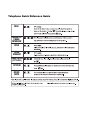
Telephone Quick Reference Guide
PAGE
PHONE-TOPHONE
INTERCOM
HOLD
DOOR
SPEAKER
DOOR LATCH
(OPTIONAL)
SYSTEM
MUSIC
MUTE