1
User Manual
TFP2A FiberMaster
Optical Time-Domain Reflectometer
070-9189-03
This document applies to firmware version T1.2E
and above. Earlier instruments may not include all
features described in this manual. Refer to appendix
E.
First Printing : November1998
Copyright 1998 Tektronix, Inc. All rights reserved. Contents of this publication may not be
reproduced in any form without the written permission of Tektronix, Inc.
Products of Tektronix, Inc. and its subsidiaries are covered by U.S. and foreign patents and/
or pending patents.
TEKTRONIX, TEK, and FiberMaster are registered trademarks of Tektronix, Inc.
Printed in U.S.A. Specification and price change privileges are reserved.
Tektronix, Inc.
P.O. Box 1000
Wilsonville, OR 97070-1000
WARNING
This equipment generates, uses, and can radiate radio-frequency energy, and if not installed and
used in accordance with the instructions manual, may cause interference to radio communications. It has been tested and found to comply with the limits for a Class A computing device pursuant to Subpart J of Part 15 of FCC Rules, which are designated to provide reasonable
protection against such interference when operated in a commercial environment. Operation of
this equipment in a residential area is likely to cause interference, in which case, the user, at his
or her own expense, will be required to take whatever measures may be required to correct the
interference.
EC Declaration of Conformity
We
Tektronix Holland N.V.
Marktweg 73A
8444 AB Heerenveen
The Netherlands
declare under sole responsibility that the
TFP2A FiberMaster
meets the intent of Directive 89/336/EEC for Electromagnetic Compatibility. Compliance was demonstrated to the following specifications as listed in the official Journal of the European Communities:
EN 50081-1 Emissions
EN 55022
IEC 1000-3-2
Radiated, Class B
Mains Current Harmonics
EN 50082-1 Immunity:
IEC 1000-4-2
IEC 1000-4-3
IEC 1000-4-4
IEC 1000-4-5
IEC 1000-4-11
Electrostatic Discharge
RF Radiated
Fast Transients
Surge
Dropout
Australia / New Zealand Declaration of Conformity
EMC
Complies with EMC provision of Radiocommunications per the following standard(s):
AN/NZS 2064. 1/2 Industrial, Scientific, and Medical Equipment: 1992
TFP2A FiberMaster User Manual
Table of Contents
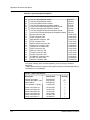
Safety Information .......................................................................... xvii
1 Introduction: the FiberMaster OTDR...................................... 1-1
Product Description ......................................................................................1-1
General Waveform Analysis .........................................................................1-4
Overview of FiberMaster Operation.............................................................1-6
The Acquisition Screen .............................................................................1-8
About this Manual .......................................................................................1-12
Conventions Used in this Manual ...........................................................1-13
Change and History Information .............................................................1-13
Unpacking and Preparation for Use ..........................................................1-14
Preparation for Use.................................................................................1-14
Repacking for Shipment..........................................................................1-20
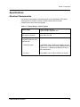
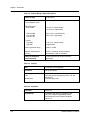
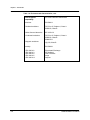
Specifications ..............................................................................................1-21
Electrical Characteristics.........................................................................1-21
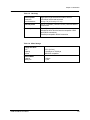
Operational Characteristics.....................................................................1-24
Physical Characteristics..........................................................................1-24
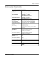
Environmental Characteristics ................................................................1-25
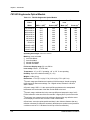
FS1300 Singlemode Optical Module ......................................................1-27
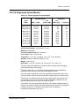
FS1500 Singlemode Optical Module ......................................................1-28
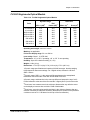
FS1315 Singlemode Optical Module ......................................................1-29
FG1300 Singlemode Optical Module ......................................................1-30
FG1315 Singlemode Optical Module ......................................................1-31
FL1300 Singlemode Optical Module.......................................................1-32
FL1500 Singlemode Optical Module.......................................................1-33
FL1315 Singlemode Optical Module.......................................................1-34
FM8500 Multimode Optical Module ........................................................1-35
FM1300 Multimode Optical Module ........................................................1-36
FM8513 Multimode Optical Module ........................................................1-37
Inspection, Cleaning, and Maintenance ....................................................1-38
Exterior Inspection ..................................................................................1-38
Exterior Cleaning ....................................................................................1-39
Optical-Fiber Cleaning ............................................................................1-39
Fuses, Filters, and Batteries ...................................................................1-41
2 Controls, Indicators, and Connectors ................................... 2-1
General Controls, Indicators, and Connectors...........................................2-2
Optical Output Controls................................................................................2-4
Cursor Controls .............................................................................................2-6
Window Controls and Indicators .................................................................2-8
Waveform Controls and Indicators............................................................2-10
TFP2A FiberMaster User Manual
v
Table of Contents
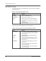
3 Getting Started......................................................................... 3-1
Power-On Defaults ........................................................................................3-4
Using FiberMaster’s Online Help .................................................................3-6
Setting up the System...................................................................................3-7
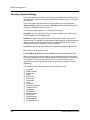
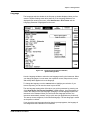
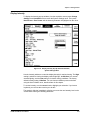
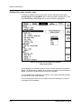
Selecting Waveform Settings....................................................................3-9
Entering Operator Settings .....................................................................3-32
Selecting System Settings ......................................................................3-34
Setting User Defaults ..............................................................................3-56
Remote Menu .........................................................................................3-59
4 Making Optical Fiber Measurements ..................................... 4-1
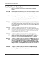
Preview Mode.................................................................................................4-3
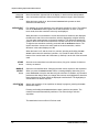
Front Panel Controls - Preview Mode .......................................................4-4
Preview Mode Measurements—Examples ...............................................4-7
Two Point Mode .............................................................................................4-9
Front-Panel Controls—Two Point Mode .................................................4-12
Two Point Measurements—Examples ....................................................4-16
Splice Loss Mode ........................................................................................4-22
Front Panel Controls – Splice Loss Mode...............................................4-24
Splice-Loss Measurements—Examples .................................................4-27
Link Return Loss Mode...............................................................................4-29
Front-Panel Controls—Link Return Loss Mode ......................................4-32
Link Return-Loss Measurements—Examples.........................................4-35
Event Return Loss Mode ............................................................................4-38
Front Panel Controls – Event Return Loss Mode ...................................4-41
Event Return-Loss Measurements—Examples ......................................4-44
5 Event Marking .......................................................................... 5-1
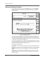
Overview.........................................................................................................5-2
Turning on Event Marking ............................................................................5-5
The Event Table .............................................................................................5-7
Reverting to Automatic Measurements ...................................................5-10
Printing the Event Table..........................................................................5-10
Event Notes..................................................................................................5-11
Entering and Editing Event Notes ...........................................................5-12
Manual Event Marking.................................................................................5-14
Entering the Place Event Markers Screen ..............................................5-15
Placing Event Markers ............................................................................5-15
Examples ................................................................................................5-17
Automatic Measurements with Manually Placed Markers ......................5-17
Storing and Retrieving Event Markers ......................................................5-18
Operational Details of Automatic Event Marking .....................................5-19
Event-Marking Examples ............................................................................5-23
vi
TFP2A FiberMaster User Manual
Table of Contents
6 Advanced Operating Functions ............................................. 6-1
The Expansion Window ................................................................................6-2
Vertical SIZE Knob....................................................................................6-3
Horizontal SIZE Knob ...............................................................................6-5
Distance CURSOR Knob ..........................................................................6-5
CURSOR SELECT Button ........................................................................6-6
Extending the Acquisition Range ................................................................6-7
High-Density Data Acquisition .....................................................................6-9
Parameter Settings and High-Density Data Acquisition..........................6-10
Storing High-Density Data ......................................................................6-10
Dual-Trace Mode..........................................................................................6-11
Aligning Waveform Scales ......................................................................6-12
Changing Instrument Settings.................................................................6-12
The Expansion Window ..........................................................................6-12
High-Density Data Acquisition ................................................................6-13
Real-Time Acquisition.................................................................................6-14
Setting Manual Masks .................................................................................6-15
Entering the Place Manual Masks Screen ..............................................6-16
Adjusting Masks......................................................................................6-17
Implementing Manual Masks ..................................................................6-19
Clearing and Replacing Manual Masks ..................................................6-19
Exiting the Place Manual Masks Screen.................................................6-20
7 Mass Storage ........................................................................... 7-1
Load from Disk ..............................................................................................7-3
Selecting a File to Load ............................................................................7-3
Loading a Waveform File ..........................................................................7-4
Loading a Settings File .............................................................................7-5
Quick Load................................................................................................7-5
Exiting the Load from Disk Menu ..............................................................7-6
Save to Disk ...................................................................................................7-7
File Format................................................................................................7-7
File Specifications .....................................................................................7-7
Saving the File ........................................................................................7-11
Quick Save..............................................................................................7-11
Exiting the Save to Disk Menu ................................................................7-12
Format ..........................................................................................................7-13
Selecting the Drive..................................................................................7-14
Exiting the Format Menu.........................................................................7-14
Delete............................................................................................................7-15
Selecting a File to Delete ........................................................................7-15
Exiting the Delete Menu..........................................................................7-16
Copy..............................................................................................................7-17
Quick Copy .............................................................................................7-18
Batch Copy .............................................................................................7-18
Exiting the Copy Menu............................................................................7-18
TFP2A FiberMaster User Manual
vii
Table of Contents
8 Remote Control........................................................................ 8-1
GPIB System ..................................................................................................8-1
GPIB Signal Lines.....................................................................................8-2
GPIB Interface Functions..........................................................................8-3
GPIB Addressing ......................................................................................8-4
GPIB Communications..............................................................................8-5
GPIB Status Reporting and Error Handling ............................................8-11
GPIB System Errors, Events, and Warnings ..........................................8-19
GPIB Message-Exchange Protocol ........................................................8-22
GPIB Controller and Instrument Synchronization ...................................8-23
GPIB Device Initialization........................................................................8-25
RS-232 System.............................................................................................8-27
RS-232 Signal Lines ...............................................................................8-28
RS-232 System Setup ............................................................................8-29
RS-232 Communications ........................................................................8-36
RS-232 Status Reporting and Error Handling .........................................8-39
RS-232 System Errors, Events, and Warnings .......................................8-43
RS-232 Controller and Instrument Synchronization................................8-46
RS-232 Device Initialization ....................................................................8-47
Similarities and Differences between GPIB and
RS-232 Remote Control ..............................................................................8-49
Differences between GPIB and RS-232 Remote Control .......................8-49
RS-232 Emulation of IEEE 488.1 Interface Messages ...........................8-53
Remote Control Data Formats....................................................................8-56
Commands and Queries .............................................................................8-62
GPIB-Only and RS-232-Only Commands and Queries ..........................8-62
Remote/Local Commands and Queries ..................................................8-73
Module-Independent Settings Commands..............................................8-75
Module-Independent Settings Queries ...................................................8-79
Module-Dependent Settings Commands ................................................8-82
Module-Dependent Settings Queries......................................................8-85
Module Information Queries....................................................................8-88
Serial-Port Settings Commands and Queries .........................................8-91
RS-232 Remote-Control Command ........................................................8-93
Acquisition Commands ...........................................................................8-94
Cursor Command and Query..................................................................8-97
Expansion Commands and Queries .......................................................8-98
Measurement Command and Queries ..................................................8-101
Event Marking and Event Table Commands and Queries ....................8-106
Event Marker Commands and Queries.................................................8-111
Waveform Selection and Storage Commands and Queries .................8-114
Waveform Data Command and Queries ...............................................8-116
Response Formatting Commands ........................................................8-121
Response Formatting Queries ..............................................................8-122
Waveform Transfer Commands and Queries .......................................8-123
Mass-Storage Commands ....................................................................8-132
Mass-Storage Queries ..........................................................................8-137
Hardcopy Commands and Queries.......................................................8-141
Display-Related Commands and Query ...............................................8-146
viii
TFP2A FiberMaster User Manual
Table of Contents
Identification Query ...............................................................................8-149
Learn Settings Queries .........................................................................8-150
Reset and Stop Commands..................................................................8-152
Status and Error-Reporting Commands................................................8-153
Status and Error-Reporting Queries .....................................................8-154
Device Synchronization Commands and Query ...................................8-156
Selftest Queries ....................................................................................8-157
GPIB Programming Example....................................................................8-158
RS-232 Programming Example ................................................................8-161
Remote Control Event Codes and Messages .........................................8-164
Queue Status Codes.............................................................................8-164
Command Errors...................................................................................8-164
Execution Errors ...................................................................................8-166
Internal Errors .......................................................................................8-172
System Events ......................................................................................8-172
Execution Warnings ..............................................................................8-173
Internal Warnings..................................................................................8-173
A Accessories and Options........................................................A-1
Mainframes .............................................................................................. A-1
Accessories.............................................................................................. A-1
Options..................................................................................................... A-3
B Keyboard Definitions...............................................................B-1
C FiberMaster Data Format ........................................................C-1
D Diagnostics Menus ..................................................................D-1
E Firmware Features...................................................................E-1
F Error Codes .............................................................................. F-1
TFP2A FiberMaster User Manual
ix
List of Illustrations
Figure 1-1. General Waveform Analysis .............................................................1-5
Figure 1-2. Features on the Acquisition Screen.................................................1-8
Figure 1-3. Acquisition Screen Expansion—Overview (top),
and Expanded View (bottom)....................................................1-9
Figure 1-4. Installing Optical Modules ..............................................................1-15
Figure 1-5. Interconnect Circuit Board Connectors.........................................1-16
Figure 1-6. Installing the Module Spacer:
Two-Module Configuration......................................................1-17
Figure 1-7. Front-Panel Option Covers .............................................................1-18
Figure 1-8. Loading Paper into the Internal Printer .........................................1-19
Figure 1-9. Cleaning and Changing the Universal Connector ........................1-40
Figure 2-1. FiberMaster Front-Panel Controls, Indicators,
and Connectors..........................................................................2-1
Figure 2-2. FiberMaster Rear-Panel Connectors ..............................................2-12
Figure 3-1. FiberMaster Start-Up Screen ............................................................3-2
Figure 3-2. Sample Help Screen ..........................................................................3-6
Figure 3-3. Pulse Width Pop-Up Selection Window,
Waveform Settings Menu ........................................................3-10
Figure 3-4. Maximum Range Pop-Up Selection Window,
Waveform Settings Menu ........................................................3-12
Figure 3-5. Maximum Averages Pop-Up Selection Window,
Waveform Settings Menu ........................................................3-14
Figure 3-6. Refractive Index Pop-Up Selection Window,
Waveform Settings Menu ........................................................3-16
Figure 3-7. Slope Calculation Pop-Up Selection Window,
Waveform Settings Menu ........................................................3-18
Figure 3-8. Scattering Coefficient Pop-Up Selection Window,
Waveform Settings Menu .......................................................3-20
Figure 3-9. Dual Trace Pop-Up Selection Window,
Waveform Settings Menu ........................................................3-22
Figure 3-10. Event Threshold Pop-Up Selection Window,
Waveform Settings Menu .......................................................3-23
Figure 3-11. Event Marking Pop-Up Selection Window,
Waveform Settings Menu .......................................................3-25
Figure 3-12. Masking Type Pop-Up Selection Window,
Waveform Settings Menu .......................................................3-27
Figure 3-13. Unmasked Reflection ....................................................................3-28
Figure 3-14. QuickMask ......................................................................................3-28
Figure 3-15. AccuMask .......................................................................................3-29
x
TFP2A FiberMaster User Manual
List of Illustrations
Figure 3-16. Filtering Pop-Up Selection Window,
Waveform Settings Menu ........................................................3-30
Figure 3-17. Operator Settings Menu ................................................................3-32
Figure 3-18. Language Pop-Up Selection Window,
System Settings Menu.............................................................3-35
Figure 3-19. Display Intensity Pop-Up Selection Window,
System Settings Menu.............................................................3-37
Figure 3-20. Display Color Pop-Up Selection Window,
System Settings Menu............................................................3-38
Figure 3-21. Sound Pop-Up Selection Window,
System Settings Menu.............................................................3-39
Figure 3-22. System Time Pop-Up Selection Window,
System Settings Menu.............................................................3-40
Figure 3-23. System Date Pop-Up Selection Window,
System Settings Menu.............................................................3-41
Figure 3-24. Date Format Pop-Up Selection Window,
System Settings Menu.............................................................3-42
Figure 3-25. Units Pop-Up Selection Window,
System Settings Menu.............................................................3-43
Figure 3-26. Keyboard Translation Pop-Up Selection Window,
System Settings Menu.............................................................3-44
Figure 3-27. File Format Pop-Up Selection Window,
System Settings Menu.............................................................3-45
Figure 3-28. Hardcopy Device Pop-Up Selection Window,
System Settings Menu.............................................................3-47
Figure 3-29. GPIB Status Pop-Up Selection Window,
System Settings Menu.............................................................3-49
Figure 3-30. GPIB Address Pop-Up Selection Window,
System Settings Menu.............................................................3-50
Figure 3-31. RS232 Baud Rate Pop-Up Selection Window,
System Settings Menu.............................................................3-51
Figure 3-32. RS232 Parity Pop-Up Selection Window,
System Settings Menu.............................................................3-52
Figure 3-33. RS232 Stop Bits Pop-Up Selection Window,
System Settings Menu.............................................................3-53
Figure 3-34. RS232 Data Bits Pop-Up Selection Window,
System Settings Menu.............................................................3-54
Figure 3-35. RS232 Flow Control Pop-Up Selection Window,
System Settings Menu.............................................................3-55
Figure 3-36. User Defaults Menu, Page 1..........................................................3-56
Figure 3-37. User Defaults Menu, Page 2..........................................................3-57
Figure 3-38. Remote Menu .................................................................................3-59
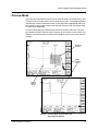
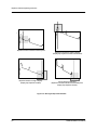
Figure 4-1. Preview Mode, Overview (top) and
Expanded View (bottom) ...........................................................4-3
TFP2A FiberMaster User Manual
xi
List of Illustrations
Figure 4-2. Preview Mode, Measuring Distance to End of Fiber.......................4-7
Figure 4-3. Preview Mode, Measuring Distance to Fusion Splice ....................4-8
Figure 4-4. Two Point Mode (Two-Point Slope Calculation) .............................4-9
Figure 4-5. Two Point Mode (LSA Slope Calculation)......................................4-10
Figure 4-6. Automatic Two-Point Measurement—Positioning the
First Distance Cursor...............................................................4-16
Figure 4-7. Automatic Two-Point Measurement—Positioning the
Second Distance Cursor .........................................................4-17
Figure 4-8. User-Adjusted Two-Point Measurement—Adjusting the
Active Loss Cursor ..................................................................4-18
Figure 4-9. User-Adjusted Two-Point Measurement—Adjusting the
Loss Cursor in Expanded View ..............................................4-19
Figure 4-10. User-Adjusted Two-Point Measurement ......................................4-19
Figure 4-11. Automatic Fiber Loss Measurement—Placing the
First Cursor...............................................................................4-20
Figure 4-12. Automatic Fiber-Loss Measurement—Placing the
Second Cursor .........................................................................4-21
Figure 4-13. Splice Loss Mode...........................................................................4-22
Figure 4-14. Automatic Splice-Loss Measurement ..........................................4-27
Figure 4-15. User-Adjusted Splice-Loss Measurement ...................................4-28
Figure 4-16. Link Return Loss Mode .................................................................4-30
Figure 4-17. Automatic Link Return-Loss Measurement—Placing the
First Cursor at the Start of the Link........................................4-35
Figure 4-18. Automatic Link Return-Loss Measurement—Placing the
Second Cursor at the End of the Link....................................4-36
Figure 4-19. User-Adjusted Link Return-Loss Measurement..........................4-37
Figure 4-20. Event Return Loss Mode...............................................................4-39
Figure 4-21. Automatic Event Return-Loss Measurement ..............................4-44
Figure 4-22. User-Adjusted Event Return-Loss Measurement .......................4-45
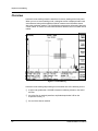
Figure 5-1. Event Marking ....................................................................................5-2
Figure 5-2. Event Table (above) and Event Notes (below) ................................5-3
Figure 5-3. Turning on Event Marking.................................................................5-5
Figure 5-4. The Event Table .................................................................................5-7
Figure 5-5. Event Notes ......................................................................................5-11
Figure 5-6. Editing Event Notes .........................................................................5-12
Figure 5-7. The Place Event Markers Screen
(Cursor on Event Marker) ........................................................5-14
Figure 5-8. The Place Event Markers Screen
(Cursor off Event Marker)........................................................5-16
Figure 5-9. The Place Event Markers Screen (Moving Event Marker) ............5-16
Figure 5-10. Event Marking and Grouped Reflective Events ..........................5-19
Figure 5-11. Event Marking and Grouped Non-Reflective Events ..................5-20
xii
TFP2A FiberMaster User Manual
List of Illustrations
Figure 5-12. Event Marking and Unmasked Grouped Events .........................5-21
Figure 5-13. Event Marking and Masked Grouped Events ..............................5-21
Figure 5-14. Event Marking and Nonreflective Gain
Produced by Waveform Reconstruction................................5-22
Figure 5-15. Event Marking and Incorrect Mask Placement............................5-22
Figure 5-16. Unmarked Fusion Splice ...............................................................5-23
Figure 5-17. Manually Marked Fusion Splice....................................................5-23
Figure 5-18. Automatically Marked Fusion Splice ...........................................5-24
Figure 5-19. Fusion Splice Undetected in Noise ..............................................5-24
Figure 5-20. Fusion Splice Automatically Detected in Noise ..........................5-25
Figure 6-1. The Expansion Window.....................................................................6-2
Figure 6-2. Moving the Expansion Window ........................................................6-4
Figure 6-3. Short Acquisition Range ...................................................................6-7
Figure 6-4. Cursor Past Acquisition Range and Resulting Prompt..................6-8
Figure 6-5. Extended Acquisition ........................................................................6-8
Figure 6-6. Dual Waveform Display ...................................................................6-11
Figure 6-7. Place Manual Masks Screen ...........................................................6-15
Figure 7-1. Load from Disk Menu: Single-Drive Instrument..............................7-3
Figure 7-2. Load Menu: Dual-Drive Instrument ..................................................7-4
Figure 7-3. Quick Load .........................................................................................7-6
Figure 7-4. Save Menu: Dual-Drive Instrument ..................................................7-8
Figure 7-5. Save Menu: Single-Drive Instrument ...............................................7-9
Figure 7-6. Format Menu: Single-Drive Instrument..........................................7-13
Figure 7-7. Format Menu: Dual-Drive Instrument.............................................7-14
Figure 7-8. Delete Menu: Single-Drive Instrument ...........................................7-15
Figure 7-9. Delete Menu: Dual-Drive Instrument ..............................................7-16
Figure 7-10. Copy Menu: Dual-Drive Instrument ..............................................7-17
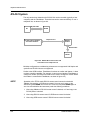
Figure 8-1. Standard and Linear Bus Configurations ........................................8-1
Figure 8-2. Sample GPIB IEEE 488 System ........................................................8-2
Figure 8-3. GPIB Status Reporting and Error Handling...................................8-13
Figure 8-4. RS-232 Direct Connection and Connection over
Telephone Line.........................................................................8-27
Figure 8-5. RS-232 Status Reporting and Error Handling ...............................8-39
Figure A-1. Connector Options........................................................................... A-4
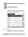
Figure D-1. Run Diagnostics Menu..................................................................... D-1
Figure D-2. Set Options Menu............................................................................. D-2
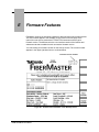
Figure E-1. Firmware Version Number on the Start-Up Screen ....................... E-1
TFP2A FiberMaster User Manual
xiii
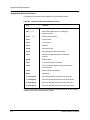
List of Tables
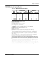
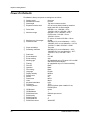
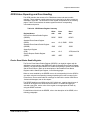
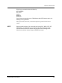
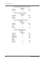
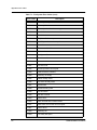
Table 1-1. Display Range—Vertical System .....................................................1-21
Table 1-2. Display Range—Horizontal System .................................................1-22
Table 1-3. Display................................................................................................1-22
Table 1-4. Keyboard ............................................................................................1-22
Table 1-5. Hardcopy ............................................................................................1-23
Table 1-6. Mass Storage .....................................................................................1-23
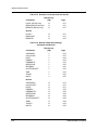
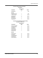
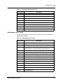
Table 1-7. Operational Characteristics..............................................................1-24
Table 1-8. Physical Characteristics ...................................................................1-24
Table 1-9. Environmental Characteristics.........................................................1-25
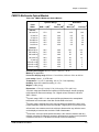
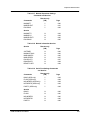
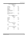
Table 1-10. FS1300 Singlemode Optical Module ..............................................1-27
Table 1-11. FS1500 Singlemode Optical Module ..............................................1-28
Table 1-12. FS1315 Singlemode Optical Module ..............................................1-29
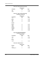
Table 1-13. FG1300 Singlemode Optical Module .............................................1-30
Table 1-14. FG1315 Singlemode Optical Module .............................................1-31
Table 1-15. FL1300 Singlemode Optical Module ..............................................1-32
Table 1-16. FL1500 Singlemode Optical Module ..............................................1-33
Table 1-17. FL1315 Singlemode Optical Module ..............................................1-34
Table 1-18. FM8500 Multimode Optical Module................................................1-35
Table 1-19. FM1300 Multimode Optical Module................................................1-36
Table 1-20. FM8513 Multimode Optical Module................................................1-37
Table 1-21. External Inspection Checklist ........................................................1-38
Table 8-1. FiberMaster GPIB Interface Functions ..............................................8-3
Table 8-2. Uniline Interface Messages ................................................................8-5
Table 8-3. Multiline Universal Interface Messages.............................................8-6
Table 8-4.
Multiline Addressed Interface Messages .........................................8-6
Table 8-5. Multiline Address Interface Messages ..............................................8-6
Table 8-6. GPIB Status Register Summary .......................................................8-11
Table 8-7. GPIB Event Code Categories ...........................................................8-19
Table 8-8. RS-232 Signal Lines ..........................................................................8-28
Table 8-9. FiberMaster-to-DTE Wiring ...............................................................8-29
Table 8-10. FiberMaster-to-DCE Wiring.............................................................8-30
Table 8-11. FiberMaster-to-DTE Wiring .............................................................8-30
Table 8-12. Hayes Accura Modem Settings for FiberMaster
Remote Control...............................................................................8-32
Table 8-13. RS-232 Status Register Summary..................................................8-39
Table 8-14. RS-232 Event Code Categories ......................................................8-43
Table 8-15. Remote/Local Commands and Queries.........................................8-64
xiv
TFP2A FiberMaster User Manual
List of Tables
Table 8-16. Module-Independent Settings Commands and Queries .............8-64
Table 8-17. Module-Dependent Settings Commands and Queries.................8-65
Table 8-18. Module Information Queries...........................................................8-65
Table 8-19. Serial Port Settings Commands and Queries ...............................8-65
Table 8-20. RS-232 Remote-Control Command................................................8-66
Table 8-21. Acquisition Commands ..................................................................8-66
Table 8-22. Cursor Movement Command and Query.......................................8-66
Table 8-23. Expansion Commands and Queries ..............................................8-66
Table 8-24. Measurement Command and Queries ...........................................8-67
Table 8-25. Event Marking and Event Table Commands and Queries ...........8-67
Table 8-26. Event Marker Commands and Queries..........................................8-68
Table 8-27. Waveform Selection and Storage Commands and Queries ........8-68
Table 8-28. Waveform Data Command and Queries ........................................8-68
Table 8-29. Response Formatting Commands and Queries ...........................8-69
Table 8-30. Waveform Transfer Commands and Queries ...............................8-69
Table 8-31. Mass-Storage Commands and Queries.........................................8-70
Table 8-32. Hardcopy Commands and Queries................................................8-71
Table 8-33. Display-Related Commands and Query ........................................8-71
Table 8-34. Identification Query.........................................................................8-71
Table 8-35. Learn Settings Queries ...................................................................8-71
Table 8-36. Reset and Stop Commands............................................................8-72
Table 8-37. Status and Error Reporting Commands and Queries ..................8-72
Table 8-38. Device Synchronization Commands and Query...........................8-72
Table 8-39. Selftest Queries ...............................................................................8-72
Table A-1. Mainframe Options ............................................................................ A-1
Table A-2. Standard Accessories ....................................................................... A-1
Table A-3. Optional Accessories ........................................................................ A-2
Table A-4. System Options.................................................................................. A-2
Table A-5. System Multimode Options............................................................... A-2
Table A-6. System Singlemode Options ............................................................ A-3
Table A-7. Option Accessories ........................................................................... A-3
Table B-1. Global Keyboard Functions .............................................................. B-1
Table B-2. Menu-System Keyboard Functions .................................................. B-2
Table B-3. Menu-System Numeric-Parameter Keyboard Functions................ B-2
Table B-4. Menu-System Alphanumeric-Parameter
Keyboard Functions ........................................................................ B-3
Table B-5. Mass-Storage Keyboard Functions.................................................. B-3
Table B-6. Acquisition-Screen Keyboard Functions ........................................ B-4
Table E-1. Firmware Versions and Features...................................................... E-2
TFP2A FiberMaster User Manual
xv
List of Tables
Table F-1. File System Error Codes ................................................................... F-1
Table F-2. Flash Memory Error Codes .............................................................. F-3
Table F-3. LED Error Codes ............................................................................... F-4
Table F-4. Phase 1 Error Codes ......................................................................... F-5
Table F-6. Phase 2 Error Codes ......................................................................... F-5
xvi
TFP2A FiberMaster User Manual
Safety Information
The general safety information in these pages is for both operating and servicing
personnel. In addition, specific warnings and cautions appear throughout the manual
where they apply.
Definition of Terms and Symbols
In this manual, a CAUTION flag identifies a potential for equipment or other property
damage.
A WARNING flag identifies a potential for personal injury or property damage.
A DANGER flag identifies an immediate hazard to personal safety or property.
Symbols that may be marked on the equipment indicate the following:
DANGER—High Voltage
!
ATTENTION—refer to manual
Protective ground (earth) terminal
Power Source
This product is designed to operate from a power source that will not apply more than
250 volts RMS between the supply conductors or between the supply conductor and
ground. A protective ground connection by way of the grounding conductor in the
power cord is essential for safe operation.
Grounding the Instrument
The instrument is grounded through the grounding conductor of the power cord. To
avoid electric shock, plug the power cord into a properly wired receptacle before
connecting to the product input or output terminals.
TFP2A FiberMaster User Manual
xvii
User Safety Summary
Danger Arising from Loss of Ground
If you lose the protective ground connection, all accessible conductive parts (including
knobs and controls that appear to be insulating) can render an electric shock.
Use the Proper Power Cord
Use only the power cord and connector specified for your product. Use only a power
cord in good condition. Refer cord and connector changes to qualified service
personnel.
Use the Proper Fuse
To avoid fire hazard, use only a fuse of the correct type, voltage rating, and current
rating as specified in the parts list for your product. Refer fuse replacement to qualified
service personnel.
Do Not Operate in Explosive Atmospheres
To avoid explosion, do not operate this product in an explosive atmosphere unless it
has been specifically certified for such operation.
Do Not Remove Covers or Panels
To avoid personal injury, do not remove the product covers or panels. Do not operate
the product without the covers or panel properly installed.
Laser Radiation
Avoid eye exposure to the laser output and open-ended fibers by covering the end or
directing the output at a non-reflective surface. FiberMaster has been classified as a
Class 1 laser product under the Radiation Control and Health Safety Act of 1968.
Repair
Refer all repair problems to qualified service personnel.
xviii
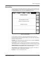
TFP2A FiberMaster User Manual
1
ATTENTION!
Introduction:
the FiberMaster OTDR
Read the Safety Information section located at the front of this manual before
operating FiberMaster.
This manual applies to the TFP2A firmware shown on the title page of this
manual. For a list of firmware releases and major features, refer to appendix E.
The information in this appendix will help you use this manual with earlier TFP2
firmware versions.
If you have questions about using FiberMaster, or have special application
problems, in the U.S. and Canada call our toll-free help line,
1-800-TEK-WIDE ext. 24, or contact your local Tektronix representative.
Product Description
The TEKTRONIX TFP2A FiberMaster Optical Time-Domain Reflectometer (OTDR) is
an optical-fiber test instrument capable of measuring loss characteristics and
displaying faults, splices, and other fiber events in singlemode and multimode optical
fibers.
FiberMaster applies pulses of light to the fiber under test via the optical output
connector. As the pulses travel through the fiber, some light is reflected back to the
instrument. These reflections are processed to display a visual representation of the
fiber on FiberMaster’s cathode ray tube (CRT), where you can make distance and
loss measurements on the fiber under test.
The CRT display is a time plot, read from left to right. The trace starts with the
outgoing pulse, and the time difference is converted to distance in the measurement
process. When you view a typical fiber display, events that are further down the fiber
appear to the right (later in time). Loss is measured on the CRT’s vertical scale.
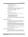
NOTE
This manual explains how to use the TFP2A FiberMaster product line, which
includes mainframe models TFP2A (color monitor) and TFP2AM (monochrome
monitor), configured with various options. (Refer to appendix A, Accessories and
Options.) In this manual, the instrument is referred to generically as
“FiberMaster” or “TFP2A,” to refer to both the TFP2A and TFP2AM models.
With the exception of a parameter on the System Settings menu used to set the
color on color monitors, the operation of the two mainframes is identical.
This manual is also compatible with TFP2/TFP2M instruments. Refer to appendix
E for a list of the firmware features that apply to earlier FiberMaster models.
TFP2A FiberMaster User Manual
1-1
Chapter 1: Introduction
Modular, Plug-In Laser Sources
❏
The FiberMaster OTDR was designed using a modular approach that allows you
to choose options that answer your specific test and measurement applications.
You can easily upgrade your instrument configuration as your system
requirements change. FiberMaster can accommodate 850-nanometer (nm)
multimode, 1300-nm multimode, 1310-nm singlemode, and 1550-nm singlemode
laser sources in one or two plug-in modules. The modules can contain either two
singlemode or two multimode lasers, or any single laser, allowing the instrument
to be configured with from one to all four wavelengths.
❏
Temperature-controlled laser light sources ensure stable wavelength and optical
output for highly accurate measurements.
Accurate, High-Speed
Data Acquisition and Measurement
❏
The internal 32-bit microprocessor performs up to 16 million high-speed
averages per acquisition, maximizing the signal-to-noise ratio, giving a clear
display of fiber events.
❏
FiberMaster measures a specific fiber feature, with single-keystroke
convenience. In addition, manual adjustments provide extended flexibility in
interpreting the fiber data.
❏
An expand function allows you to magnify any portion or feature on the displayed
fiber acquisition.
❏
FiberMaster’s high-density acquisition capability offers extended expansion
capacity and highly accurate measurements.
❏
A masking function can be performed automatically, or you can set manual
masks to eliminate detector saturation caused by large Fresnel reflections,
improving measurement linearity.
Automatic and Manual Event Marking
1-2
❏
The instrument’s event-marking function automatically locates and measures
events on the fiber under test that have splice losses above a user-specified
threshold, or you can also mark events manually.
❏
An event table is compiled displaying the measurements for each marked event.
You can edit and print out this table, plus enter notes and mapping information
about each event.
TFP2A FiberMaster User Manual
Chapter 1: Introduction
Extended Memory and
Storage Capacity
❏
FiberMaster offers both a current memory, containing the current data
acquisition, and a reference memory, for previously acquired fiber waveform
data. A dual-trace mode makes it possible to display the contents of both current
and reference memory simultaneously, allowing you to compare a current
optical-fiber acquisition to historical data.
❏
Mass-storage devices (the standard floppy-disk drive and optional internal RAM)
permit unlimited storage of waveform and settings data on both removable and
internal media.
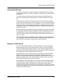
Hardcopy Options
❏
You can choose the optional high-speed internal thermal printer, or use
FiberMaster with either an IEEE 488 general-purpose interface bus (GPIB)
external plotter or printer, or an RS232 external plotter or printer. One press of a
button on the instrument’s front panel provides a 15-second hard copy of the
displayed waveform and instrument settings on the internal printer.
Remote Control Capability
❏
The FiberMaster OTDR can be operated under the remote control of an
instrument controller or a computer with a GPIB interface, using an IEEE 488
general-purpose interface bus, or via the RS-232 serial interface.
Additional Features
❏
An easy-to-use menu system simplifies setting instrument measurement
parameters.
❏
You can upload and download waveform and settings data using the RS232
interface and XModem protocol.
❏
The 7-inch diagonal, high-resolution color or monochrome CRT provides a
comprehensive on-screen readout of waveform and measurement data, and
instrument settings.
❏
Online help displays context-sensitive operator assistance at the press of a
button.
❏
Rugged, portable construction is also lightweight—under 35 pounds (15
kilograms).
TFP2A FiberMaster User Manual
1-3
Chapter 1: Introduction
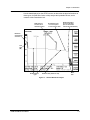
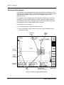
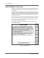
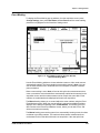
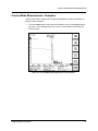
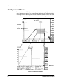
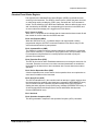
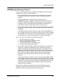
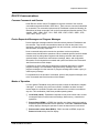
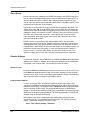
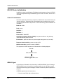
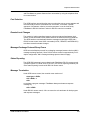
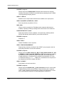
General Waveform Analysis
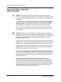
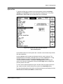
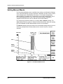
Figure 1-1 shows an optical fiber waveform acquisition typical of the data you might
see on the FiberMaster CRT. The horizontal axis shows the distance from
FiberMaster’s front-panel connector to points along the fiber under test. The vertical
axis measures reflected light detected by the OTDR, and represents transmission
loss along the fiber length.
The leftmost spike is a reflection caused by the front-panel connector. The sloping
waveform is backscattered light (light reflected back towards its source) that shows
fiber characteristics. The slope of the waveform represents the optical fiber loss. A
low-loss, homogeneous fiber will show a gradually sloping waveform.
Any breaks or connections along the fiber appear on the display as either reflective or
nonreflective discontinuities in the waveform, as shown in figure 1-1. These
discontinuities, or “events,” indicate locations along the fiber where you might find a
splice, connector, bend, break, or other anomaly in the cable.
1-4
TFP2A FiberMaster User Manual
Chapter 1: Introduction
Use the data displayed on the OTDR’s screen to determine the physical locations of
these types of optical-fiber faults, to help analyze their probable causes, and to
measure cable transmission loss.
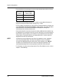
Reflective loss
at connector or
mechanical splice
Nonreflective loss,
i.e. a fusion splice
or a bend in the cable
Reflective break at
the end of the fiber
(the end of the fiber
can also be nonreflective)
Reflection
at front-panel
connector
Loss
scale
(dB)
Backscattered
light
Distance scale (meters or feet)
Noise
floor
Figure 1-1. General Waveform Analysis
TFP2A FiberMaster User Manual
1-5
Chapter 1: Introduction
Overview of FiberMaster Operation
Start data acquisition on a fiber-optic cable under test by simply connecting the cable
to the appropriate front-panel connector, and pressing the START/STOP button. An
averaged waveform appears on the screen, and you can make measurements
immediately.
The FiberMaster OTDR provides five measurement modes for viewing faults and
measuring transmission loss, fusion-splice loss, connection loss, return loss, and
other characteristics of fiber-optic cable. These are Preview, Two Point, Splice Loss,
and two Return Loss modes.
❏
Preview mode gives a clear overview of the fiber. Scan fiber features and
measure distances in Preview mode.
❏
Two Point mode allows you to measure loss between any two points on the fiber.
❏
Splice Loss mode gives loss measurements at splice points along the fiber.
❏
Link Return Loss mode lets you measure the return loss of a fiber link.
❏
Event Return Loss shows the return loss for a particular event on the fiber.
Enter each measurement mode by pressing a front-panel softkey. Two-point, spliceloss, and return-loss measurements can be made automatically. Front-panel controls
permit manual adjustment to automatic measurements.
Automatic and manual event-marking modes locate and perform measurements on
all events on the fiber under test. An online table is compiled that contains two-point,
splice-loss, return-loss, and distance measurements for each event. You can adjust
measurement values on the table, and enter and edit notes for each event.
A general-purpose interface bus (GPIB) and the RS-232 serial interface allow remote
control of the instrument.
Advanced Functions
FiberMaster’s automatic measurements provide adequate data for many applications.
If you require more in-depth fiber analysis, however, the instrument’s advanced
functions offer extended flexibility in acquiring and interpreting fiber data. These
functions include:
❏
❏
❏
❏
❏
1-6
High-density data acquisition
A dual-waveform display, for comparing two waveforms
Manipulation of the expansion window
Real-time acquisition
Manual-masking capabilities
TFP2A FiberMaster User Manual
Chapter 1: Introduction
Instrument Configuration
Instrument configuration and measurement settings are set through a menu system,
accessed by pressing a front-panel softkey. You can set parameters using various
front-panel controls to enter the data, or you can connect an optional IBM-ATcompatible keyboard to FiberMaster for data entry.
Mass Storage
The mass-storage system is also entered through a front-panel softkey, for storing
waveform and settings data on floppy disks or an optional internal RAM. Data is
saved in MS-DOS-compatible files.
TFP2A FiberMaster User Manual
1-7
Chapter 1: Introduction
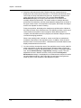
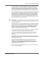
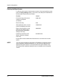
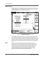
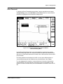
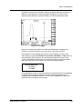
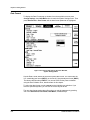
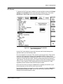
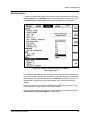
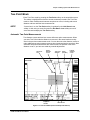
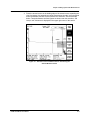
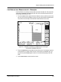
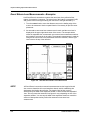
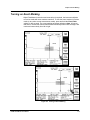
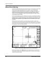
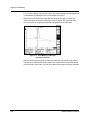
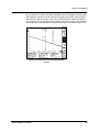
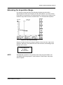
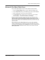
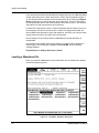
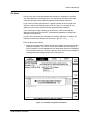
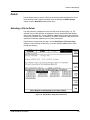
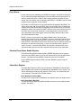
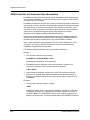
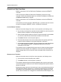
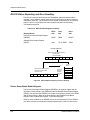
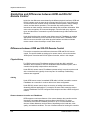
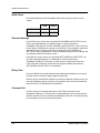
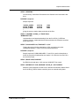
The Acquisition Screen
The acquisition screen displays fiber test data and measurement information, and is
used for all fiber-evaluation activity. Other than instrument setup, event marking, and
mass-storage operations, most of your work with FiberMaster will be on the
acquisition screen.
The acquisition screen displays either data acquisition in progress or a completed
acquisition, including all measurements on the fiber under test. Distance and loss
cursors display on this screen, depending on the measurement mode, and can be
manipulated to perform manual measurements on the fiber.
The acquisition screen includes:
❏
A horizontal distance scale and a vertical loss scale.
❏
One or two distance cursors, and one or two loss cursors, depending on the
measurement mode.
Expansion
window
Active
distance
cursor
Vertical
scale (dB)
Inactive
distance
cursor
Waveform
settings
Loss
cursors
Horizontal scale
(kilometers or kilofeet)
Softkey labels
Figure 1-2. Features on the Acquisition Screen
1-8
TFP2A FiberMaster User Manual
Chapter 1: Introduction
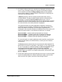
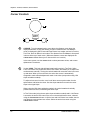
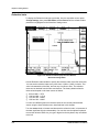
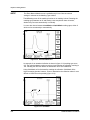
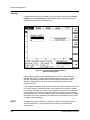
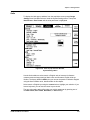
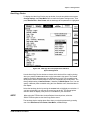
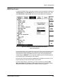
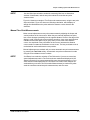
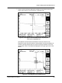
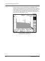
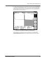
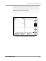
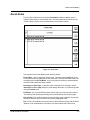
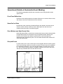
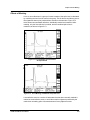
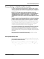
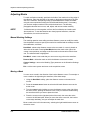
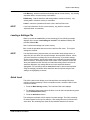
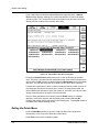
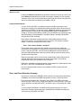
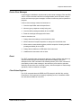
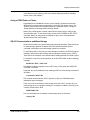
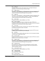
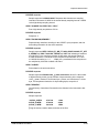
❏
An expansion window. Pressing the EXPAND button on the front panel switches
between expanded view and overview. In expanded view, the area within the
expansion window is magnified to fill the display, allowing closer examination of
the fiber. See figure 1-3.
Figure 1-3. Acquisition Screen Expansion—Overview (top),
and Expanded View (bottom)
TFP2A FiberMaster User Manual
1-9
Chapter 1: Introduction
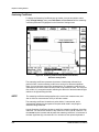
❏
Waveform and measurement data. Distance and loss measurements are
displayed on the screen near the waveform. In Two Point mode and both returnloss modes, the slope calculation and return loss, respectively, appears in the
upper right-hand corner of the screen. The message User Adjusted
Measurement displays in the upper left-hand corner of the screen for all
manually adjusted measurements. The actual number of averages that were
performed on the waveform, and the actual elapsed averaging time are shown in
the upper center screen. If an acquisition is in progress, the number of averages
and the time elapsed are seen increasing.
During an acquisition, the display also contains an acquisition-active indicator in
the lower-left corner of the waveform area. This indicator provides a quick way to
check whether an acquisition is still in progress. When data acquisition is
complete, and calculations are still in progress, the indicator changes to show a
clock with a swinging pendulum.
When event-marking mode is turned on, events on the fiber are marked and
numbered at the bottom of the acquisition screen. In addition, when the active
distance cursor is on an event marker, a field below the horizontal distance scale
displays measurements for that event.
❏
1-10
On color monitors, the waveform area of the acquisition screen is color coded for
easier interpretation of data and measurements. Waveform data, including the
active waveform (except for high-density data), the number of averages, elapsed
time, and the Normal Density or High Density message, is green. The useradjustable elements—distance and loss cursors, and the User Adjusted
Measurement message—are displayed in red. Measurement values such as the
two-point distance and loss, splice loss, fiber loss, and return loss figures are
shown in yellow. Event markers are also displayed in yellow.
TFP2A FiberMaster User Manual
Chapter 1: Introduction
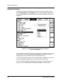
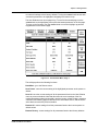
❏
All waveform settings used for the acquisition are displayed at the bottom of the
screen. These user-defined settings are selected on the Waveform Settings
menu, reached by pressing the Change Settings softkey on the acquisition
screen. Refer to chapter 3, Getting Started, for information on configuring your
instrument and setting parameters.
A Module parameter in the list of settings indicates which laser source is
currently selected. The type of module is shown, plus the currently selected
wavelength. For example, FS1315-1310SM indicates that the 1310-nm
wavelength of a dual-wavelength singlemode FS-type optical module is currently
selected. If the active module is different from the one that was used to acquire
the current waveform, the module parameter is highlighted.
The module parameter may include alphabetical characters to indicate the
modification level of the module, and whether the module has an internal fiber
with a non-standard core diameter. This information is appended to the
wavelength. Lower-case letters indicate the modification level of the module, and
upper-case letters stand for a non-standard core diameter. For example:
FS1315-1310SM — standard module with standard core diameter
FS1315-1310SMaA — modified module with non-standard core diameter
FS1315-1310SMA — standard module with non-standard core diameter
FS1315-1310SMa — modified module with standard core diameter
For more information on module modifications and internal fiber core diameters,
in the U.S. and Canada, call 1-800-833-9200, or contact your local Tektronix
representative.
The Source parameter shows where the current waveform data originated. The
data could be the result of an acquisition, a data transfer, or from a mass-storage
file. For an acquisition, the parameter displays as Source = Acquisition. If the
waveform was loaded from mass storage, the parameter reads File =
<FILE_NAME> where <FILE_NAME> is the name of the mass-storage file. If the
waveform data was received via an XModem data transfer, the parameter reads
Source = XModem.
❏
Softkey labels display along the right-hand edge of the screen. On the acquisition
screen, the softkeys allow you to switch measurement modes, view the event
table, enter the menu system, and access mass-storage functions.
TFP2A FiberMaster User Manual
1-11
Chapter 1: Introduction
About this Manual
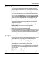
The FiberMaster User Manual consists of seven chapters and six appendices,
containing the following information:
1-12
❏
Chapter 1, Introduction, provides a description of the FiberMaster OTDR,
unpacking and repacking instructions, instrument specifications, and user
maintenance.
❏
Chapter 2, Controls, Indicators, and Connectors, describes the functions of each
of the front- and rear-panel controls and connectors.
❏
Chapter 3, Getting Started, explains how to use the online help function, lists
settings defaults, and describes the menu system used to configure the
instrument and set measurement parameters.
❏
Chapter 4, Making Optical Fiber Measurements, describes each of the
measurement modes—Preview, Two Point, Splice Loss, Link Return Loss, and
Event Return Loss—and how to make automatic and manual measurements on
a fiber in these modes.
❏
Chapter 5, Event Marking, explains the process of locating, measuring, and
documenting events on the fiber under test. Events can be marked either
automatically or manually. An event table of measurements is compiled, based
on the locations of the event markers.
❏
Chapter 6, Advanced Operating Functions, outlines advanced aspects of some of
FiberMaster’s features, including details on the expansion window, high-density
data acquisition, dual waveform operation, and real-time mode.
❏
Chapter 7, Mass Storage, explains how to use the mass-storage device(s)
(floppy disk drive, internal RAM) to store and retrieve waveform and settings
data.
❏
Chapter 8, Remote Control, contains the remote-control command set and
instructions on how to use the instrument under remote control via GPIB and RS232.
❏
Appendices contain information that applies to general operation of the
instrument. They include a list of options and accessories available for use with
the FiberMaster OTDR, a description of the instrument’s data output, a list of
keyboard sequences recognized by the instrument, how to run the instrument’s
diagnostic self tests, a list of firmware versions, a list of start-up error codes, and
instructions on how to upgrade software via floppy disk.
TFP2A FiberMaster User Manual
Chapter 1: Introduction
Conventions Used
in this Manual
In the text of this manual, references to front-panel controls and softkeys appear in
boldface type, for example:
Press the START/STOP button.
Change instrument settings by pressing the Change Settings softkey.
Remote-control commands and messages as sent and received by the instrument
are shown indented and in upper-case, boldface type:
ACQUIRE 10.0,START,NORMAL;*OPC?
Change and History Information
Change information that involves manual corrections and additional data is located at
the back of this manual in the Change Information section. History information with
the updated data is integrated into the text or diagrams when a page is updated.
TFP2A FiberMaster User Manual
1-13
Chapter 1: Introduction
Unpacking and Preparation for Use
Before unpacking FiberMaster from its shipping container or carton, inspect for signs
of external damage. If the carton is damaged, notify the carrier. The shipping carton
contains the instrument and its standard and optional accessories.
If the contents of the shipping container are incomplete, if there is mechanical
damage or defects, or if the instrument does not meet operational check
requirements, contact your local Tektronix Field Office or representative. If the
shipping container is damaged, notify the carrier as well as Tektronix.
The instrument was inspected both mechanically and electrically before shipment. It
should be free of mechanical damage and meet or exceed all electrical
specifications. Functional and operational self tests are performed at power-on. If
your instrument fails to perform satisfactorily, contact your Tektronix representative
immediately, or in the U.S. and Canada, telephone toll free 1-800-TEK-WIDE ext.
2400.
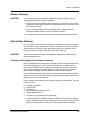
Preparation for Use
Use FiberMaster’s front cover to protect the front panel when storing and transporting
the instrument. Remove the cover by pulling out on the sides and lifting off. Replace
the cover by pressing it over the front panel until the cover snaps in place. The
instrument’s accessories are stored in the soft carrying case.
You can position FiberMaster’s handle to serve as a tilt stand, or you can move it to
the front of the instrument, so the instrument can be stacked or carried. To position
the handle, press in at both pivot points and rotate to the desired position.
Power Source and Power Requirements
FiberMaster is intended to be operated from a power source that does not apply more
than 250V RMS between the supply conductors, or between either supply conductor
and ground. A protective ground connection by way of the grounding conductor in the
power cord is essential for safe operation.
The AC power connector is a three-wide, polarized plug with the ground (earth) lead
connected directly to the instrument frame to provide electrical shock protection. If
the unit is connected to any other power source, the unit frame must be connected to
an earth ground.
CAUTION
1-14
To avoid electric shock, the power cord protective grounding conductor must be
connected to ground.
TFP2A FiberMaster User Manual
Chapter 1: Introduction
Power and voltage requirements are printed on the back panel. With the DC power
option (option 17), FiberMaster can be operated from 11 to 16 VDC, or from 90 to
250 VAC nominal line voltage at 47 to 73 Hz. AC-only instruments can be operated
from 90 to 250 VAC, 47 to 73 Hz.; or from 90 to 130 VAC, 47 to 440 Hz. In AC-only
instruments, power-source selection is made automatically when the unit is plugged
in.
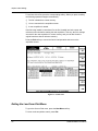
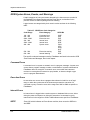
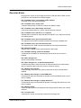
Installing the Optical Module(s)
Your TFP2A mainframe may be shipped with optical module(s) installed. If you order
modules separately, you may have to install them at your site. Install one or two
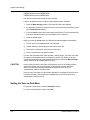
optical modules into the mainframe as follows:
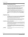
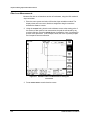
1. Detach the left-hand side of the mainframe back panel by unscrewing four black
quick-release screws in each corner of the back-panel assembly (see figure 1-4).
Pull the back-panel assembly off the mainframe using the handle provided,
disconnecting the control and module support boards from the interconnect board,
which is attached to the inside of the back panel.
Backpanel
quick-release screws
Module
quick-release screws
Backpanel
quick-release screws
Figure 1-4. Installing Optical Modules
TFP2A FiberMaster User Manual
1-15
Chapter 1: Introduction
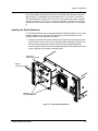
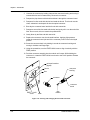
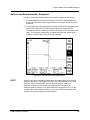
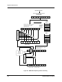
2. Plug one module into the bottom set of module connectors on the interconnect
board, inserting the module’s screwholes through the back-panel assembly. (See
figure 1-5.)
3. Secure the module to the back-panel assembly by tightening the two back-panel
quick-release screws into the module’s screwholes.
4. If you have a second module, plug it into the top set of module connectors on the
interconnect board.
Module support
board connectors
Module connectors
(use for second module)
Module connectors
(use for single module)
Control board
connector
Figure 1-5. Interconnect Circuit Board Connectors
5. Secure the second module to the back-panel assembly by tightening the two quickrelease screws into the module’s screwholes.
1-16
TFP2A FiberMaster User Manual
Chapter 1: Introduction
6. If you are installing two modules, snap the spacer between the modules as shown
in figure 1-6, into the holes provided .
7. Place the modules inside the mainframe, lining up the fiber connectors with the
openings in the front panel, and reconnecting the control and module support
boards to the interconnect board.
NOTE
Align the connectors on the interconnect board correctly to ensure complete
connections with the module support board, optical module(s), and control board.
If connections are not made properly, the instrument will not work.
8. Reattach the back-panel assembly to the mainframe by tightening the four black
quick-release screws. All the screws in the back-panel assembly can be tightened
further using a screwdriver, if necessary.
To take the modules out of the TFP2A mainframe, reverse this procedure.
Figure 1-6. Installing the Module Spacer:
Two-Module Configuration
TFP2A FiberMaster User Manual
1-17
Chapter 1: Introduction
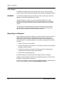
Front-Panel Covers
If your instrument includes one optical module, the top module slot on the front panel
is unused. If your instrument is not configured with a floppy-disk drive, the drive slot is
unused. Unused option slots are covered before the instrument is shipped from the
factory. If you change your instrument’s configuration, however, you may need to
remove or install these covers, as shown in figure 1-7.
Option-port
cover
Disk-drive
cover
Figure 1-7. Front-Panel Option Covers
1-18
TFP2A FiberMaster User Manual
Chapter 1: Introduction
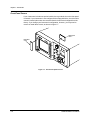
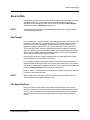
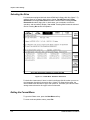
Loading Paper into the Internal Printer
To load paper into the internal thermal printer, follow these steps:
1. Slide the printer cover back.
2. Lift out the old paper roll and remove the black disks from either end.
3. Insert the disks into the ends of the new paper roll.
4. Place the new roll into the printer, with the end of the paper coming out from under
the roll towards the front of the instrument.
5. Push the paper tension lever down, and hold it down for step 6.
6. Feed the paper into the slot in the paper guide, until it comes out in front of the
aluminum paper guide. See figure 1-8. The arrows indicate the direction in which
to feed the paper.
7. Release the tension lever.
When the printer is in use, slide the printer cover closed until it reaches the stops
provided for the paper opening. Use the serrated edge of the cover as a guide to tear
the paper off. After printing, tear off any remaining paper and slide the cover
completely closed over the printer.
Paper tension
lever
Figure 1-8. Loading Paper into the Internal Printer
TFP2A FiberMaster User Manual
1-19
Chapter 1: Introduction
Laser Output
FiberMaster is equipped with low-energy lasers and does not output continuous
energy unless you have started data acquisition (by pressing the START/STOP button).
WARNING
The TFP2A FiberMaster has been classified as a Class 1 laser product under the
Radiation Control and Health Safety Act of 1968.
Although output from a Class 1 laser is not considered hazardous, it is good
practice not to allow eye exposure from direct or reflected laser light. This can be
avoided by covering the end of the fiber or directing the output at a non-reflective
surface.
It is important to set up and operate the instrument as instructed in this manual.
Use of controls or adjustments for performance of procedures other than those
specified herein may result in hazardous radiation exposure.
Repacking for Shipment
When packing an instrument for shipping to a Tektronix Service Center for service or
repair, attach a tag showing the name and address of the owner, name of the
individual at your firm to contact, complete serial number, and a description of the
service required. If the original packaging is not available, repackage the instrument
as follows:
1. Install the front cover on the OTDR.
2. Position the handle over the front cover, and wrap the instrument in polyethylene
sheeting to protect the finish.
3. Cushion the instrument on all sides with packing material or urethane foam
between the carton and the sides of the instrument.
4. Seal the carton using shipping tape.
No special handling is required to prepare the floppy-disk drive for shipping.
A shipping carton and packing material can be obtained through your local Tektronix
field office or representative, if necessary.
If you have any questions, contact your local Tektronix field office or representative or
in the U.S. and Canada call toll free 1-800-TEK-WIDE ext. 2400.G
1-20
TFP2A FiberMaster User Manual
Chapter 1: Introduction
Specifications
Electrical Characteristics
The following characteristics and features apply to the FiberMaster OTDR after a
warmup period of at least 20 minutes. All loss numbers reflect one-way
measurements unless otherwise specified.
Table 1-1. Display Range—Vertical System
Vertical range
Loss measurements
Loss readout resolution
1 dB to 50 dB, overview
1 dB to 100 dB, expanded view
0.001 dB to 0.01 dB
Accuracy
Two point, splice loss, and
LSA fiber loss:
FM/FS/FG series
±0.05 dB/dB, from 7 dB above the RMS noise floor
(SNR = 1) to 30 dB on the screen. Maximum error of
±0.2 dB from +7 dB above the RMS noise floor to
top of backscatter.
FL series
±0.02 dB/dB, from 15 dB to 35 dB on the screen.
TFP2A FiberMaster User Manual
1-21
Chapter 1: Introduction
Table 1-2. Display Range—Horizontal System
Distance range
1 m to 200 km
Distance measurements
Cursor resolution (min)
FM/FS/FG series:
850 nm MM
1300 nm MM/
1310 nm SM/
1550 nm SM
5 cm to 2 m, normal density;
1 cm to 50 cm, high density
20 cm to10 m, normal density;
10 cm to 2 m, high density
FL series:
1310 SM/
1550 SM
2 m to 10 m, normal density;
no high density
Index of refraction range
1.4000 to 1.6000
Distance measurement
accuracy
±0.001%, ±minimum cursor resolution
±uncertainty in index of refraction
Number of displayed
waveform points
>16,000 maximum for each normal and
high density
Table 1-3. Display
Size
7 inches (17.5 cm) diagonal
Resolution
640 by 480 pixels
Display type
Color
Monochrome
Two-color system giving three colors, with five
levels each
Five-level gray scale
Table 1-4. Keyboard
1-22
Connector
5-pin RJ11
Compatibility
Compatible with IBM AT keyboards (input
only), but complete compatibility can be
guarenteed only with Tektronix keyboard
Option 19
TFP2A FiberMaster User Manual
Chapter 1: Introduction
Table 1-5. Hardcopy
Internal printer
Resolution
Print dimensions
High-speed, high-resolution dot matrix, thermal
150 dots/in vertical and horizontal
4 in by 5 in (10.2 cm by 12.7 cm)
External plotter
HP-GL compatible (Tektronix HC100): GPIB and RS232
connections
External printer
Epson FX-compatible: RS232 connection
Hewlett-Packard ThinkJet/LaserJet-compatible: GPIB
and RS232 connections
PostScript-compatible: RS232 connection
Table 1-6. Mass Storage
Floppy disk drive
Size
Capacity
Format
3.5 in (8.9 cm)
1.44 Mbyte or 720 Kbyte
MS-DOS compatible
Internal RAM
Capacity
Battery life
1 Mbyte
1 year
TFP2A FiberMaster User Manual
1-23
Chapter 1: Introduction
Operational Characteristics
Table 1-7. Operational Characteristics
Power requirements
AC operation (AC only)
90 - 130 VAC, 47 - 440Hz
180 - 250 VAC, 47 - 73Hz
(auto select)
AC operation (AC with DC option)
90 - 130 VAC, 47 - 73 Hz
180 - 250 VAC, 47 - 73 Hz
DC operation
11 - 16 VDC
Power supply rating
AC operation
250 watts max.
315 VA max.
DC operation
200 VA max. (watts)
Module capacity
Two dual-wavelength modules
maximum, for a total of four
wavelengths
Safety
UL 1244, UL 3111-1
CSA: CAN/CSA C22.2 No. 231
CAN/CSA -C22.2 No. 1010.192
IEC 1010-1
EN 61010-1
Physical Characteristics
Table 1-8. Physical Characteristics
1-24
Weight
33 lbs (15 kg), mainframe configured with floppydisk drive, internal printer, and one optical module
Dimensions
Overall dimensions, including front cover, handle,
and feet:
Length, 25 in (63.7 cm);
width, 18 in (46 cm);
height, 7 in (18 cm)
TFP2A FiberMaster User Manual
Chapter 1: Introduction
Environmental Characteristics
Table 1-9. Environmental Characteristics
Temperature
Mainframe
Operating: +5˚ to +50˚ C
Non-operating: -40˚ to +60˚ C
With internal printer
Operating: +5˚ to +40˚ C
Non-operating: -20˚ to +60˚ C
Without floppy-disk drive
Operating: -10˚ to +55˚ C
Non-operating: -40˚ to +70˚ C
Humidity (operating)
Mainframe
With internal printer
Without floppy-disk drive
Altitude (maximum)
Operating
Non-operating
Sine vibration
Operating
Disk drive non-operating
8% to 75% (+5%, -0%), noncondensing
35% to 75% (+5%, -0%), noncondensing
5% to 90% (+5%, -0%), noncondensing
15,000 ft (4.6 km)
50,000 ft (15.2 km)
Tek 062-2847-00, Class 3 (exceeds MIL-T28800E)
Frequency sweep: 10 to 55 Hz
Loading: 0.5G, maximum
Frequency sweep: 10 to 55 Hz
Loading: 2.0G, maximum
Shock (maximum)
Operating
5G
Disk drive non-operating
30G
Bench handling
MIL-T-28800E
Transit drop
MIL-T-28800E
Water resistance
Drip proof, tested with front cover on
Fungus resistance
Enclosure and electronics are fungus inert by
design
TFP2A FiberMaster User Manual
1-25
Chapter 1: Introduction
Table 1-9. Environmental Characteristics, cont.
Electromagnetic
compatibility
EC Council Directive 89/336/EEC
Emissions:
EN 50081-1
Radiated emissions
FCC Part 15, Subpart J, Class A
EN55022, Class B
Mains Current Harmonics
IEC 1000-3-2
Conducted emissions
FCC Part 15, Subpart J, Class A
EN55022, Class B
EN60555-2
Magnetic emissions
Vfg 243, Class B
Immunity:
IEC 1000-4-2
IEC 1000-4-3
IEC 1000-4-4
IEC 1000-4-5
IEC 1000-4-11
1-26
EN 50082-1
Electrostatic Discharge
RF Radiated
Fast Transients
Surge
Dropout
TFP2A FiberMaster User Manual
Chapter 1: Introduction
FS1300 Singlemode Optical Module
Table 1-10. FS1300 Singlemode Optical Module
Dynamic Range1
Pulse
Width
SNR = 1 (dB)2
10 µs/1000 m
4000 ns/400 m
2000 ns/200 m
1000 ns/100 m
500 ns/50 m
200 ns/20 m
100 ns/10 m
50 ns/5 m
50 ns/5 m HR
20 ns/2 m HR
10 ns/1 m HR
End
Detect. (dB)3
29.5
27.5
23.5
22.0
20.5
18.5
17.0
15.5
12.0
10.5
9.0
38.0
38.0
38.0
38.0
38.0
38.0
38.0
38.0
34.0
34.0
34.0
Dead Zone
Loss
Meas. (m)4
Event (m)5
1080
480
240
140
70
40
25
20
15
NA
NA
1050
420
220
110
55
25
12
7
7
5
3
Operating wavelength: 1310 nm ± 20 nm
Masking: menu selectable
❏
❏
❏
❏
Auto-QuickMask
Auto-AccuMask
Manual-QuickMask
Manual-AccuMask
Full-screen display range: 50 m to 200 km
Laser safety: Class 1, 21 CFR 1040
Temperature: -10˚ to +55˚ C operating; -40˚ to +70˚ C non-operating
Humidity: Up to 90% relative humidity (+5, -0%)
Weight: 4.4 lbs (<2 kg)
Dimensions: 1.75 in (4.5 cm) by 5.5 in (14.0 cm) by 17.5 in (44.5 cm)
1
Dynamic range specifications are based on 32,000 averages. Actual averaging
times depend on instrument settings. For 3 Sigma values, subtract 2.4 dB from
SNR=1 values.
2
Dynamic range, SNR = 1 is the one-way difference between the extrapolated
backscatter level at the start of the fiber and the RMS noise level.
3
Dynamic range, end detection is the one-way difference between the top of a 4%
Fresnel reflection at the start of the fiber and the 3 Sigma (99.5%) level of the noise.
4
Dead zone, loss measurement is the minimum distance after any reflective event
on the display to measure loss to within 0.5 dB of backscatter.
5
Dead zone, event (two-point spatial resolution) is the minimum distance after any
reflection necessary to determine accurately the distance to another event (based on
a minimum recover of 1.5 dB down from the top of the first reflection).
TFP2A FiberMaster User Manual
1-27
Chapter 1: Introduction
FS1500 Singlemode Optical Module
Table 1-11. FS1500 Singlemode Optical Module
Dynamic Range1
Pulse
Width
SNR = 1 (dB)2
10 µs/1000 m
4000 ns/400 m
2000 ns/200 m
1000 ns/100 m
500 ns/50 m
200 ns/20 m
100 ns/10 m
50 ns/5 m
50 ns/5 m HR
20 ns/2 m HR
10 ns/1 m HR
End
Detect. (dB)3
26.5
24.5
20.5
19.0
17.5
15.5
14.0
12.5
9.0
7.5
5.0
36.0
36.0
36.0
36.0
36.0
36.0
36.0
36.0
33.0
33.0
33.0
Dead Zone
Loss
Meas. (m)4
Event (m)5
1080
480
240
140
70
40
25
20
18
NA
NA
1050
420
220
110
55
25
12
7
7
5
3
Operating wavelength: 1550 nm ± 20 nm
Masking: menu selectable
❏
❏
❏
❏
Auto-QuickMask
Auto-AccuMask
Manual-QuickMask
Manual-AccuMask
Full-screen display range: 50 m to 200 km
Laser safety: Class 1, 21 CFR 1040
Temperature: -10˚ to +55˚ C operating; -40˚ to +70˚ C non-operating
Humidity: Up to 90% relative humidity (+5, -0%)
Weight: 4.4 lbs (<2 kg)
Dimensions: 1.75 in (4.5 cm) by 5.5 in (14.0 cm) by 17.5 in (44.5 cm)
1
Dynamic range specifications are based on 32,000 averages. Actual averaging
times depend on instrument settings. For 3 Sigma values, subtract 2.4 dB from
SNR=1 values.
2
Dynamic range, SNR = 1 is the one-way difference between the extrapolated
backscatter level at the start of the fiber and the RMS noise level.
3
Dynamic range, end detection is the one-way difference between the top of a 4%
Fresnel reflection at the start of the fiber and the 3 Sigma (99.5%) level of the noise.
4
Dead zone, loss measurement is the minimum distance after any reflective event
on the display to measure loss to within 0.5 dB of backscatter.
5
Dead zone, event (two-point spatial resolution) is the minimum distance after any
reflection necessary to determine accurately the distance to another event (based on
a minimum recover of 1.5 dB down from the top of the first reflection).
1-28
TFP2A FiberMaster User Manual
Chapter 1: Introduction
FS1315 Singlemode Optical Module
Table 1-12. FS1315 Singlemode Optical Module
Dynamic Range1
Pulse
Width
10 µs/1000 m
4000 ns/400 m
2000 ns/200 m
1000 ns/100 m
500 ns/50 m
200 ns/20 m
100 ns/10 m
50 ns/5 m
50 ns/5 m HR
20 ns/2 m HR
10 ns/1 m HR
SNR = 1 (dB)2
29.5/26.5
27.5/24.5
23.5/20.5
22.0/19.0
20.5/17.5
18.5/15.5
17.0/14.0
15.5/12.5
12.0/9.0
10.5/7.5
9.0/5.0
End
Detect. (dB)3
38.0/36.0
38.0/36.0
38.0/36.0
38.0/36.0
38.0/36.0
38.0/36.0
38.0/36.0
38.0/36.0
34.0/33.0
34.0/33.0
34.0/33.0
Dead Zone
Loss
Meas. (m)4
Event (m)5
1080
480
240
140
70
40
25
20
15/18
NA
NA
1050
420
220
110
55
25
12
7
7
5
3
Operating wavelengths: 1310/1550 nm ± 20 nm
Masking: menu selectable
❏
❏
❏
❏
Auto-QuickMask
Auto-AccuMask
Manual-QuickMask
Manual-AccuMask
Full-screen display range: 50 m to 200 km
Laser safety: Class 1, 21 CFR 1040
Temperature: -10˚ to +55˚ C operating; -40˚ to +70˚ C non-operating
Humidity: Up to 90% relative humidity (+5, -0%)
Weight: 4.4 lbs (<2 kg)
Dimensions: 1.75 in (4.5 cm) by 5.5 in (14.0 cm) by 17.5 in (44.5 cm)
1
Dynamic range specifications are based on 32,000 averages. Actual averaging
times depend on instrument settings. For 3 Sigma values, subtract 2.4 dB from
SNR=1 values.
2
Dynamic range, SNR = 1 is the one-way difference between the extrapolated
backscatter level at the start of the fiber and the RMS noise level.
3
Dynamic range, end detection is the one-way difference between the top of a 4%
Fresnel reflection at the start of the fiber and the 3 Sigma (99.5%) level of the noise.
4
Dead zone, loss measurement is the minimum distance after any reflective event
on the display to measure loss to within 0.5 dB of backscatter.
5
Dead zone, event (two-point spatial resolution) is the minimum distance after any
reflection necessary to determine accurately the distance to another event (based on
a minimum recover of 1.5 dB down from the top of the first reflection).
TFP2A FiberMaster User Manual
1-29
Chapter 1: Introduction
FG1300 Singlemode Optical Module
Table 1-13. FG1300 Singlemode Optical Module
Dynamic Range1
Pulse
Width
SNR = 1 (dB)2
10 µs/1000 m
4000 ns/400 m
2000 ns/200 m
1000 ns/100 m
500 ns/50 m
200 ns/20 m
100 ns/10 m
50 ns/5 m
50 ns/5 m HR
20 ns/2 m HR
10 ns/1 m HR
End
Detect. (dB)3
31.0
28.5
25.5
24.0
21.5
19.5
18.0
16.5
13.5
11.5
9.5
38.0
38.0
38.0
38.0
38.0
38.0
38.0
38.0
34.0
34.0
34.0
Dead Zone
Loss
Meas. (m)4
Event (m)5
1150
550
250
150
80
55
50
45
30
25
N/A
1150
475
225
110
55
25
12
10
7
5
4
Operating wavelength: 1310 nm ± 20 nm
Masking: not applicable
Full-screen display range: 50 m to 200 km
Laser safety: Class 1, 21 CFR 1040
Temperature: -10˚ to +55˚ C operating; -30˚ to +70˚ C non-operating
Humidity: Up to 90% relative humidity (+5, -0%)
Weight: 4.4 lbs (<2 kg)
Dimensions: 1.75 in (4.5 cm) by 5.5 in (14.0 cm) by 17.5 in (44.5 cm)
1
Dynamic range specifications are based on 32,000 averages. Actual averaging
times depend on instrument settings.
2
Dynamic range, SNR = 1 is the one-way difference between the extrapolated
backscatter level at the start of the fiber and the RMS noise level.
3
Dynamic range, end detection is the one-way difference between the top of a 4%
Fresnel reflection at the start of the fiber and the 3 Sigma (99.5%) level of the noise.
4
Dead zone, loss measurement is the minimum distance after any reflective event
on the display to measure loss to within 0.5 dB of backscatter. Specifications are
based on reflections not to exceed a return loss of 40 dB.
5
Dead zone, event (two-point spatial resolution) is the minimum distance after any
reflection necessary to determine accurately the distance to another event (based on
a minimum recover of 1.5 dB down from the top of the first reflection).
Performance specifications are at 25˚ C.
1-30
TFP2A FiberMaster User Manual
Chapter 1: Introduction
FG1315 Singlemode Optical Module
Table 1-14. FG1315 Singlemode Optical Module
Dynamic Range1
Pulse
Width
10 µs/1000 m
4000 ns/400 m
2000 ns/200 m
1000 ns/100 m
500 ns/50 m
200 ns/20 m
100 ns/10 m
50 ns/5 m
50 ns/5 m HR
20 ns/2 m HR
10 ns/1 m HR
SNR = 1 (dB)2
End
Detect. (dB)3
31.0/29.0
28.5/26.5
25.5/23.5
24.0/22.0
21.5/19.5
19.5/17.5
18.0/16.0
16.5/14.5
13.5/11.5
11.5/9.5
9.5/7.5
38.0/36.0
38.0/36.0
38.0/36.0
38.0/36.0
38.0/36.0
38.0/36.0
38.0/36.0
38.0/36.0
34.0/33.0
34.0/33.0
34.0/33.0
Dead Zone
Loss
Meas. (m)4
Event (m)5
1150
550
250
150
80/85
55/60
50/55
45/55
30/35
25/30
N/A
1150
475
225
110
55
25
12
10
7
5
4
Operating wavelengths: 1310/1550 nm ± 20 nm
Masking: not applicable
Full-screen display range: 50 m to 200 km
Laser safety: Class 1, 21 CFR 1040
Temperature: -10˚ to +55˚ C operating; -30˚ to +70˚ C non-operating
Humidity: Up to 90% relative humidity (+5, -0%)
Weight: 4.4 lbs (<2 kg)
Dimensions: 1.75 in (4.5 cm) by 5.5 in (14.0 cm) by 17.5 in (44.5 cm)
1
Dynamic range specifications are based on 32,000 averages. Actual averaging
times depend on instrument settings.
2
Dynamic range, SNR = 1 is the one-way difference between the extrapolated
backscatter level at the start of the fiber and the RMS noise level.
3
Dynamic range, end detection is the one-way difference between the top of a 4%
Fresnel reflection at the start of the fiber and the 3 Sigma (99.5%) level of the noise.
4
Dead zone, loss measurement is the minimum distance after any reflective event
on the display to measure loss to within 0.5 dB of backscatter. Specifications are
based on reflections not to exceed a return loss of 40 dB.
5
Dead zone, event (two-point spatial resolution) is the minimum distance after any
reflection necessary to determine accurately the distance to another event (based on
a minimum recover of 1.5 dB down from the top of the first reflection).
Performance specifications are at 25˚ C.
TFP2A FiberMaster User Manual
1-31
Chapter 1: Introduction
FL1300 Singlemode Optical Module
Table 1-15. FL1300 Singlemode Optical Module
Dynamic Range1
Pulse
SNR = 1 (dB)2
20 µs/2000 m
10 µs/1000 m
4000 ns/400 m
2000 ns/200 m
1000 ns/100 m
500 ns/50 m
200 ns/20 m
100 ns/10 m
Dead Zone
End
Detect (dB)3
37.5
36.0
33.5
31.0
29.5
27.5
25.5
24.0
46.0
46.0
45.5
44.5
44.5
44.0
44.0
44.0
Meas. (m)4
2375
1270
670
395
280
150
125
125
Event (m)5
2100
1050
440
220
120
60
35
25
Operating wavelength: 1310 nm ± 20 nm
Masking: not applicable
Full-screen display range: 50 m to 320 km
Laser safety: Class 1, 21 CFR 1040
Temperature: -10˚ to +55˚ C operating; -40˚ to +70˚ C non-operating
Humidity: Up to 90% relative humidity (+5, -0%)
Weight: 4.4 lbs (<2 kg)
Dimensions: 1.75 in (4.5 cm) by 5.5 in (14.0 cm) by 17.5 in (44.5 cm)
1
Dynamic range specifications are based on 262,000 averages. Actual averaging
times depend on instrument settings. For 3 Sigma values, subtract 2.4 dB from
SNR=1 values.
2
Dynamic range, SNR = 1 is the one-way difference between the extrapolated
backscatter level at the start of the fiber and the RMS noise level.
3
Dynamic range, end detection is the one-way difference between the top of a 4%
Fresnel reflection at the start of the fiber and the 3 Sigma (99.5%) level of the noise.
4
Dead zone, loss measurement is the minimum distance after any reflective event
on the display to measure loss to within 0.5 dB of backscatter.
5
Dead zone, event (two-point spatial resolution) is the minimum distance after any
reflection necessary to determine accurately the distance to another event (based on
a minimum recover of 1.5 dB down from the top of the first reflection).
1-32
TFP2A FiberMaster User Manual
Chapter 1: Introduction
FL1500 Singlemode Optical Module
Table 1-16. FL1500 Singlemode Optical Module
Dynamic Range1
Pulse
SNR = 1 (dB)2
20 µs/2000 m
10 µs/1000 m
4000 ns/400 m
2000 ns/200 m
1000 ns/100 m
500 ns/50 m
200 ns/20 m
100 ns/10 m
Dead Zone
End
Detect (dB)3
37.0
35.0
33.0
30.5
29.0
27.0
25.0
23.0
46.5
46.0
46.0
45.0
45.0
44.5
44.5
44.0
Meas. (m)4
2375
1270
670
395
280
150
195
170
Event (m)5
2100
1050
440
220
120
60
35
25
Operating wavelength: 1550 nm ± 20 nm
Masking: not applicable
Full-screen display range: 50 m to 320 km
Laser safety: Class 1, 21 CFR 1040
Temperature: -10˚ to +55˚ C operating; -40˚ to +70˚ C non-operating
Humidity: Up to 90% relative humidity (+5, -0%)
Weight: 4.4 lbs (<2 kg)
Dimensions: 1.75 in (4.5 cm) by 5.5 in (14.0 cm) by 17.5 in (44.5 cm)
1
Dynamic range specifications are based on 262,000 averages. Actual averaging
times depend on instrument settings. For 3 Sigma values, subtract 2.4 dB from
SNR=1 values.
2
Dynamic range, SNR = 1 is the one-way difference between the extrapolated
backscatter level at the start of the fiber and the RMS noise level.
3
Dynamic range, end detection is the one-way difference between the top of a 4%
Fresnel reflection at the start of the fiber and the 3 Sigma (99.5%) level of the noise.
4
Dead zone, loss measurement is the minimum distance after any reflective event
on the display to measure loss to within 0.5 dB of backscatter.
5
Dead zone, event (two-point spatial resolution) is the minimum distance after any
reflection necessary to determine accurately the distance to another event (based on
a minimum recover of 1.5 dB down from the top of the first reflection).
TFP2A FiberMaster User Manual
1-33
Chapter 1: Introduction
FL1315 Singlemode Optical Module
Table 1-17. FL1315 Singlemode Optical Module
Dynamic Range1
Pulse
SNR = 1 (dB)2
20 µs/2000 m
10 µs/1000 m
4000 ns/400 m
2000 ns/200 m
1000 ns/100 m
500 ns/50 m
200 ns/20 m
100 ns/10 m
37.5/37.0
36.0/35.0
33.5/33.0
31.0/30.5
29.5/29.0
27.5/27.0
25.5/25.0
24.0/23.0
Dead Zone
End
Detect (dB)3
Meas. (m)4
Event (m)5
46.0/46.5
46.0/46.0
45.5/46.0
44.5/45.0
44.5/45.0
44.0/44.5
44.0/44.5
44.0/44.0
2375
1270
670
395
280
150
125/195
125/170
2100
1050
440
220
120
60
35
25
Operating wavelength: 1310/1550 nm ± 20 nm
Masking: not applicable
Full-screen display range: 50 m to 320 km
Laser safety: Class 1, 21 CFR 1040
Temperature: -10˚ to +55˚ C operating; -40˚ to +70˚ C non-operating
Humidity: Up to 90% relative humidity (+5, -0%)
Weight: 4.4 lbs (<2 kg)
Dimensions: 1.75 in (4.5 cm) by 5.5 in (14.0 cm) by 17.5 in (44.5 cm)
1
Dynamic range specifications are based on 262,000 averages. Actual averaging
times depend on instrument settings. For 3 Sigma values, subtract 2.4 dB from
SNR=1 values.
2
Dynamic range, SNR = 1 is the one-way difference between the extrapolated
backscatter level at the start of the fiber and the RMS noise level.
3
Dynamic range, end detection is the one-way difference between the top of a 4%
Fresnel reflection at the start of the fiber and the 3 Sigma (99.5%) level of the noise.
4
Dead zone, loss measurement is the minimum distance after any reflective event
on the display to measure loss to within 0.5 dB of backscatter.
5
Dead zone, event (two-point spatial resolution) is the minimum distance after any
reflection necessary to determine accurately the distance to another event (based on
a minimum recover of 1.5 dB down from the top of the first reflection).
1-34
TFP2A FiberMaster User Manual
Chapter 1: Introduction
FM8500 Multimode Optical Module
Table 1-18. FM8500 Multimode Optical Module
Dynamic Range1
Pulse
Width
100 ns/10 m
50 ns/5 m
20 ns/2 m
8 ns/80 cm
3 ns/30 cm
1 ns/10 cm
SNR = 1 (dB)2
End
Detect. (dB)3
27.0
25.5
23.5
20.5
16.5
14.0
36.0
36.0
36.0
36.0
35.0
35.0
Dead Zone
Loss
Meas. (m)4
Event (m)5
13.0
8.5
6.0
4.5
3.5
2.5
10.5
5.5
3.0
1.0
0.5
0.2
Operating wavelength: 850 nm ± 25 nm
Masking: not applicable
Full-screen display range: 5 m to 20 km
Laser safety: Class 1, 21 CFR 1040
Temperature: 0˚ to +50˚ C operating; -40˚ to +70˚ C non-operating
Humidity: Up to 90% relative humidity (+5, -0%)
Weight: 4.4 lbs (<2 kg)
Dimensions: 1.75 in (4.5 cm) by 5.5 in (14.0 cm) by 17.5 in (44.5 cm)
1
Dynamic range specifications are based on 32,000 averages. Actual averaging
times depend on instrument settings. For 3 Sigma values, subtract 2.4 dB from
SNR=1 values.
2
Dynamic range, SNR = 1 is the one-way difference between the extrapolated
backscatter level at the start of the fiber and the RMS noise level.
3
Dynamic range, end detection is the one-way difference between the top of a 4%
Fresnel reflection at the start of the fiber and the 3 Sigma (99.5%) level of the noise.
4
Dead zone, loss measurement is the minimum distance after any reflective event
on the display to measure loss to within 0.5 dB of backscatter.
5
Dead zone, event (two-point spatial resolution) is the minimum distance after any
reflection necessary to determine accurately the distance to another event (based on
a minimum recover of 1.5 dB down from the top of the first reflection).
TFP2A FiberMaster User Manual
1-35
Chapter 1: Introduction
FM1300 Multimode Optical Module
Table 1-19. FM1300 Multimode Optical Module
Dynamic Range1
Pulse
Width
SNR = 1 (dB)2
1000 ns/100 m
500 ns/50 m
200 ns/20 m
100 ns/10 m
50 ns/5 m
50 ns/5 m HR
20 ns/2 m HR
10 ns/1 m HR
26.5
23.5
21.5
20.0
18.5
15.0
13.0
15.0
End
Detect. (dB)3
38.0
38.0
38.0
38.0
38.0
35.0
35.0
35.0
Dead Zone
Loss
Meas. (m)4
Event (m)5
125
65
35
30
25
20
18
14
110
55
25
12
7
7
5
3
Operating wavelength: 1300 nm ± 30 nm
Masking: not applicable
Full-screen display range: 50 m to 100 km
Laser safety: Class 1, 21 CFR 1040
Temperature: 0˚ to +50˚ C operating; -40˚ to +70˚ C non-operating
Humidity: Up to 90% relative humidity (+5, -0%)
Weight: 4.4 lbs (<2 kg)
Dimensions: 1.75 in (4.5 cm) by 5.5 in (14.0 cm) by 17.5 in (44.5 cm)
1
Dynamic range specifications are based on 32,000 averages. Actual averaging
times depend on instrument settings. For 3 Sigma values, subtract 2.4 dB from
SNR=1 values.
2
Dynamic range, SNR = 1 is the one-way difference between the extrapolated
backscatter level at the start of the fiber and the RMS noise level.
3
Dynamic range, end detection is the one-way difference between the top of a 4%
Fresnel reflection at the start of the fiber and the 3 Sigma (99.5%) level of the noise.
4
Dead zone, loss measurement is the minimum distance after any reflective event
on the display to measure loss to within 0.5 dB of backscatter.
5
Dead zone, event (two-point spatial resolution) is the minimum distance after any
reflection necessary to determine accurately the distance to another event (based on
a minimum recover of 1.5 dB down from the top of the first reflection).
1-36
TFP2A FiberMaster User Manual
Chapter 1: Introduction
FM8513 Multimode Optical Module
Table 1-20. FM8513 Multimode Optical Module
Dynamic Range1
Pulse
Width
SNR = 1 (dB)2
End
Detect. (dB)3
27.0
25.5
23.5
20.5
16.5
14.0
36.0
36.0
36.0
36.0
35.0
35.0
26.5
23.5
21.5
20.0
18.5
15.0
13.0
15.0
38.0
38.0
38.0
38.0
38.0
35.0
35.0
35.0
Dead Zone
Loss
Meas. (m)4
Event (m)5
850 nm:
100 ns/10 m
50 ns/5 m
20 ns/2 m
8 ns/80 cm
3 ns/30 cm
1 ns/10 cm
13.0
8.5
6.0
4.5
3.5
2.5
10.5
5.5
3.0
1.0
0.5
0.2
1300 nm:
1000 ns/100 m
500 ns/50 m
200 ns/20 m
100 ns/10 m
50 ns/5 m
50 ns/5 m HR
20 ns/2 m HR
10 ns/1 m HR
125
65
35
30
25
20
18
14
110
55
25
12
7
7
5
3
Operating wavelengths: 850 nm ± 25 nm, 1300 nm ± 30 nm
Masking: not applicable
Full-screen display range: 850 nm—5 m to 20 km; 1300 nm—50 m to 100 km
Laser safety: Class 1, 21 CFR 1040
Temperature: 0˚ to +50˚ C operating; -40˚ to +70˚ C non-operating
Humidity: Up to 90% relative humidity (+5, -0%)
Weight: 4.4 lbs (<2 kg)
Dimensions: 1.75 in (4.5 cm) by 5.5 in (14.0 cm) by 17.5 in (44.5 cm)
1
Dynamic range specifications are based on 32,000 averages. Actual averaging
times depend on instrument settings. For 3 Sigma values, subtract 2.4 dB from
SNR=1 values.
2
Dynamic range, SNR = 1 is the one-way difference between the extrapolated
backscatter level at the start of the fiber and the RMS noise level.
3
Dynamic range, end detection is the one-way difference between the top of a 4%
Fresnel reflection at the start of the fiber and the 3 Sigma (99.5%) level of the noise.
4
Dead zone, loss measurement is the minimum distance after any reflective event
on the display to measure loss to within 0.5 dB of backscatter.
5
Dead zone, event (two-point spatial resolution) is the minimum distance after any
reflection necessary to determine accurately the distance to another event (based on
a minimum recover of 1.5 dB down from the top of the first reflection).
TFP2A FiberMaster User Manual
1-37
Chapter 1: Introduction
Inspection, Cleaning, and Maintenance
FiberMaster’s cabinet minimizes dust accumulation inside the instrument. Never
operate the OTDR without the cabinet installed. When storing or transporting the
instrument, make sure the front cover is on to protect the front panel and display from
dust and damage.
Inspect and clean your FiberMaster OTDR as often as operating conditions require.
For example, under average conditions (laboratory use), inspect and clean your
instrument after every 1000 hours of operation. When using FiberMaster extensively
in the field, inspect and clean it after every 500 hours of operation. Dirt acts as a
thermal insulator and can cause overheating and component breakdown. It also
provides an electrical conduction path that could cause instrument failure, especially
under high-humidity conditions.
External inspection and cleaning procedures are included in this section. Internal
inspection and cleaning are beyond the scope of the user manual, and are included
in the FiberMaster Module-Level Service Manual. Refer to this manual for assembly
and disassembly procedures and instructions on inspecting and cleaning the interior
of the instrument.
Exterior Inspection
Inspect the outside of the OTDR for damage, wear, and missing parts, using table
1-19 as a guide. OTDRs that appear to have been dropped or otherwise abused
should be checked thoroughly to verify correct operation and performance.
Table 1-21. External Inspection Checklist
1-38
Item
Inspect For
Repair Action
Cabinet, front panel
cover, handle
Cracks, scratches,
deformations, damaged
hardware or gaskets,
proper operation of handle
Replace defective module.
Front-panel knobs
Missing, damaged, or loose
knobs
Repair or replace missing or
damaged knobs.
Connectors
Broken shells, cracked
insulation, deformed contacts.
Dirt in connectors.
Replace defective modules.
Clear or wash out dirt.
Accessories
Missing items or parts of
items, bent pins, broken or
frayed cables, and damaged
connectors.
Replace damaged or
missing items, frayed
cables, and defective
modules.
TFP2A FiberMaster User Manual
Chapter 1: Introduction
Exterior Cleaning
CAUTION
To prevent getting moisture inside the OTDR during external cleaning, use only
enough liquid to dampen the cloth or applicator.
1. Remove dust from the outside of the instrument by wiping with a lint-free cloth or
brushing the surface with a small brush. Use the brush to remove dust from around
the front-panel controls.
2. Clean remaining dirt with a lint-free cloth dampened in a general-purpose
detergent-and-water solution. Do not use abrasive cleaners.
3. Clean the monitor screen with a lint-free cloth dampened with isopropyl alcohol.
Optical-Fiber Cleaning
As a rule, clean any fiber before connecting it to FiberMaster’s front panel, or at any
time you think it may be contaminated. Clean the connector using electronics-grade
isopropyl alcohol on a lint-free swab, then blow dry with clean, canned air. If you
know the connector is clean, blowing with air should be sufficient.
CAUTION
Never use any abrasive material to clean the fiber. Damage to the fiber results in
deteriorated performance.
Cleaning and Changing the Front-Panel Connector
Newer FiberMaster optical modules have cleanable, universal front-panel connectors,
while older modules do not. The universal connector system is identified by the
nomenclature FREE and LOCK printed on the adapter plate inside the door of the
optical connector assembly. Clean both types of connectors before connecting a
fiber, and when changing connector adapters on the universal connectors.
Clean FiberMaster’s old-style front-panel connector with electronics-grade isopropyl
alcohol and a small lint-free swab. Insert the end of the swab into the connector, roll it
gently, then blow dry using canned air.
Clean or change the universal connector system following the steps below. The tools
you will need are:
❏
❏
❏
❏
❏
Flat-blade screwdriver
Lint-free swab
Pipe cleaner
Electronics-grade isopropyl alcohol
Optical-grade canned air
1. Lift the door of the optical connector assembly.
2. Using the flat-blade screwdriver, rotate the FREE-LOCK screw in either direction
until it is aligned vertically with the FREE position, then rotate it back to the LOCK
position. This releases the connector from the universal interface assembly.
TFP2A FiberMaster User Manual
1-39
Chapter 1: Introduction
3. Unscrew the connector by holding it around the connector knurling and turning it
counterclockwise until it rotates freely. Remove the connector.
4. Dampen the pipe cleaner with alcohol and draw it through the connector barrel.
5. Dampen a lint-free swab with alcohol and swab the ferrule. The ferrule must be
clean, otherwise it can deposit dirt into the optical connector.
6. Blow dry the connector barrel and the ferrule with canned air.
7. Dampen a second lint-free swab with alcohol and gently roll it over the end of the
fiber. Do not scrub; this can scratch the polished end.
8. Gently blow dry the fiber end with canned air.
9. Replace the connector over the universal interface. Applying light pressure,
rotate the connector barrel (the end of the connector) until it locks in the keyed
position.
10. Screw the connector back in by holding it around the connector knurling and
turning it clockwise until finger tight.
11. Using the screwdriver, turn the FREE-LOCK screw to align it vertically with the
FREE position.
12. Push the connector assembly into the module until it stops. While holding the
connector in, rotate the FREE-LOCK screw back to the LOCK position. Release
the connector.
universal interface
(pigtail)
ferrule
fiber
Å
Å
connector
knurling
ÄÄÄÄ
ÄÄÄÄ
ÄÄÄÄ
ÄÄ
ÄÄ
connector
connector
barrel
FREE – LOCK
screw
swab
pipe
cleaner
Figure 1-9. Cleaning and Changing the Universal Connector
1-40
TFP2A FiberMaster User Manual
Chapter 1: Introduction
Fuses, Filters, and Batteries
There are no fuses, filters, or batteries in the FiberMaster that can be changed or
maintained by the user.
TFP2A FiberMaster User Manual
1-41
Chapter 1: Introduction
1-42
TFP2A FiberMaster User Manual
2
Controls, Indicators, and
Connectors
The functions of FiberMaster’s controls, indicators, and connectors are described in
this chapter. Figures 2-1 and 2-2 illustrate their locations.
2
1
3
17
8
9 11 10
6
15 12 14 13 16 18 4
7
5
Figure 2-1. FiberMaster Front-Panel Controls, Indicators, and Connectors
TFP2A FiberMaster User Manual
2-1
Chapter 2: Controls, Indicators, and Connectors
General Controls, Indicators,
and Connectors
1
POWER - Pushing this button in turns on FiberMaster and starts the power-on
sequence of self tests and displays. (The power-on sequence is described in chapter
3, Getting Started.) Pushing the POWER button a second time turns off power to the
FiberMaster.
To quick-start the instrument, push the POWER button while holding down the START/
STOP button. Release the START/STOP button after you see the message Starting
operating system... on the instrument screen. Quick-start makes the instrument
bypass the power-on diagnostics, causing the start-up screen to appear faster.
Do not quick-start your instrument every time it is powered on. Allow the instrument
to run the power-on diagnostics periodically to detect any malfunctions that might
have occurred.
2
HARD COPY - When you push this button, the current contents of the display are
printed on the printer selected on FiberMaster’s System Settings menu. This device
could be, for example, the internal printer, an external GPIB plotter, a serial plotter, or
a serial printer. (Refer to chapter 3, Getting Started, for instructions on using
FiberMaster’s menu system.)
A printer (either internal or external) produces waveform prints when an acquisition is
displayed on the screen and you press the HARDCOPY button. When any other screen
is displayed (i.e., a menu screen), the printer produces a hard copy of the screen.
The external plotters (RS232 or GPIB) only produce waveform plots. If you press the
HARDCOPY button when any screen other than an acquisition screen is displayed, a
beep sounds to indicate that no plot will be made.
If you use an external GPIB plotter or printer, pressing the HARDCOPY button causes
the instrument’s GPIB status to reset temporarily to talk only, for the duration of the
plot. When the hard copy finishes, the instrument automatically switches back to the
original GPIB status setting. (Refer to chapter 3, Getting Started, for information on
setting GPIB settings.)
Waveform prints include the date and time the acquisition was started, the
measurement mode used, and the current instrument settings. If the acquisition
screen was in dual trace mode, instrument settings for both waveforms are printed.
Whether the screen includes user-adjusted measurements or high-density data is
also noted on the printout, as well as the actual number of averages performed and
the elapsed acquisition time. The fiber ID, notes, and operator’s name are also
printed, as entered on the Operator Settings menu.
2-2
TFP2A FiberMaster User Manual
Chapter 2: Controls, Indicators, and Connectors
3
HELP - Push the HELP button to read help information on the current operation being
performed by FiberMaster. For example, if the instrument is in Splice Loss mode,
pressing the HELP button lets you read explanations on splice-loss measurement and
the functions of the front-panel controls in Splice Loss mode. In the menu system,
pressing the HELP button displays information about the currently selected setting.
4
REMOTE - When lighted, this indicator shows that FiberMaster is under remote
control via GPIB.
5
KEYBOARD - Connector for an optional keyboard. Connect any IBM-AT-compatible
keyboard to FiberMaster to duplicate the front-panel controls. Keyboard sequences
recognized by the instrument are listed in appendix B. The keyboard must be
plugged into the instrument before you turn on the power.
TFP2A FiberMaster User Manual
2-3
Chapter 2: Controls, Indicators, and Connectors
Optical Output
Controls
MODULE
SELECT
START/
STOP
HOLD FOR REAL TIME
6
MODULE SELECT - Pushing this button selects the laser source. On the power-on
screen, press this button to cycle through all available optical modules. On the
acquisition screen, however, when you press the MODULE SELECT button, the
following message displays:
Press START/STOP
to acquire
new data.
Press MODULE SELECT to cycle through all installed modules until you reach the
desired wavelength. Each time you push the button, the next available laser source is
selected, wrapping from the bottom laser to the top. The corresponding indicator
lights up to show which laser is currently selected. After making your selection, press
the START/STOP button. A new acquisition is started, using the new wavelength.
The module parameter in the list of settings at the bottom of the acquisition screen
shows which laser source is selected. The type of module is shown, plus the current
wavelength. For example, FS1315-1310SM indicates that the 1310-nm wavelength of
a dual-wavelength singlemode FS-type optical module is currently selected. If the
active module is different from the one used to acquire the current waveform, the
module parameter is highlighted until you start a new acquisition.
The module parameter may include alphabetical characters to indicate the
modification level of the module, and whether the module has an internal fiber with a
non-standard core diameter. This information is appended to the wavelength. Lowercase letters indicate the modification level of the module, and upper-case letters
stand for a non-standard core diameter. For example:
FS1315-1310SM — standard module with standard core diameter
FS1315-1310SMaA — modified module with non-standard core diameter
FS1315-1310SMA — standard module with non-standard core diameter
FS1315-1310SMa — modified module with standard core diameter
For more information on module modifications and internal fiber core diameters, in
the U.S. and Canada, call 1-800-833-9200, or contact your local Tektronix
representative.
Five settings are specific to each laser source. These are pulse width, maximum
range, refractive index, scattering coefficient, and masking type (refer to the following
chapter for details on instrument settings and configuration). When you change laser
sources, the values of these settings last used with the selected laser are recalled.
The power-on defaults for the selected laser are used if no other parameter values
have been specified.
2-4
TFP2A FiberMaster User Manual
Chapter 2: Controls, Indicators, and Connectors
The power-on defaults for these five settings remain in effect until changed on the
User Defaults menu, or if you install a different type of optical module. When you
install a new optical module, the factory defaults for each laser are used, unless the
new module is the same type as the module that was removed. In this case, the
previously defined defaults are retained and recalled for the new module’s laser(s).
If the pulse width, maximum range, or masking type changes when you change laser
sources, the parameter is highlighted in the list of waveform settings at the bottom of
the acquisition screen. This indicates that the new value of the setting is different
from the one used to acquire the current waveform. When you press START/STOP to
acquire data using the new laser selection, the highlighted setting values are used
and the highlighting is cleared. The refractive index and scattering coefficient do not
require a new acquisition in order to take effect.
7
START/STOP - Pressing this button once begins an averaged waveform acquisition
in current memory. The acquisition is for the complete fiber as defined by the current
maximum-range setting.
If the active distance cursor is on the waveform when a new acquisition is started, the
new acquisition has the same starting point as the previous acquisition. If the active
distance cursor is not on the waveform when the START/STOP button is pressed, the
waveform is centered around the active distance cursor, unless limited by the
maximum range. (In these cases, the waveform is acquired against either the
rightmost or leftmost limit of the maximum range.)
An averaged acquisition stops when the selected number of averages is complete. If
an acquisition is in progress, pushing the START/STOP button stops it.
(The maximum-range setting and averaging time are selected on the Waveform
Settings menu. Refer to chapter 3, Getting Started, for information on setting
parameters.)
If you expand a waveform so that only 100 data points are displayed (by pressing the
EXPAND button, or turning the horizontal SIZE knob), pressing the STOP/START button
starts a high-density acquisition.
Pushing and holding the START/STOP button for two seconds starts a real-time
acquisition. In real time, the maximum-averages parameter is ignored, and
waveforms are acquired and displayed as rapidly as possible. To stop a real-time
acquisition, press the START/STOP button again. In real time, the instrument
automatically enters Two Point mode.
(Refer to chapter 6, Advanced Operating Functions, for more information on highdensity and real-time acquisitions.)
TFP2A FiberMaster User Manual
2-5
Chapter 2: Controls, Indicators, and Connectors
Cursor Controls
CURSOR
CURSOR
SELECT
LOSS
8
CURSOR - Turn the CURSOR knob to move the active distance cursor along the
displayed waveform to any point where you want a measurement. One distance
cursor is displayed in Splice Loss and Event Return Loss modes, and two in Preview,
Two Point, and Link Return Loss modes. The distance from FiberMaster’s front panel
is shown at the top of each cursor. (When two distance cursors are displayed, the
CURSOR SELECT button allows you to choose which one is active.)
In the menu system, use the CURSOR knob to select parameter values, and to enter
alphanumeric characters.
9
Vertical LOSS - This knob (the left-hand LOSS knob) is active in Two Point, Splice
Loss, Link Return Loss, and Event Return Loss modes, and allows you to adjust loss
measurements manually. Turning the vertical LOSS knob moves the active loss cursor
up and down. When you turn the knob, the active loss cursor is automatically
elongated to make manual adjustments easier in the noise (except when using LSA
slope calculation method).
To adjust a loss cursor in noise, move it until there are an equal number of noise
spikes above and below the cursor. Use the slope LOSS knob to match the cursor
slope to the signal slope.
When using the LSA slope-calculation method, the vertical LOSS knob vertically
positions the loss cursor, maintaining the same slope.
In Two Point mode (using the two-point slope-calculation method) and in Link Return
Loss mode, the active loss cursor is the one on the active distance cursor, selected
using the CURSOR SELECT button. In Splice Loss and Link Return Loss modes, there is
one distance cursor and two loss cursors. Select the active loss cursor using the
CURSOR SELECT button.
2-6
TFP2A FiberMaster User Manual
Chapter 2: Controls, Indicators, and Connectors
10
Slope LOSS - This knob (the right-hand LOSS knob) is active in Two Point, Splice
Loss, Link Return Loss, and Event Return Loss modes, and allows you to rotate the
active loss cursor manually to match the slope of the signal.
When you turn the slope LOSS knob, the active loss cursor is automatically elongated
to make manual adjustments easier (except when using the LSA slope calculation
method).
When using the LSA slope calculation method, the slope LOSS knob rotates the LSA
loss cursor around the point where it touches the active distance cursor.
In Two Point mode (using the two-point slope-calculation method) and Link Return
Loss mode, the active loss cursor is the one on the active distance cursor, selected
using the CURSOR SELECT button. In Splice Loss and Event Return Loss modes, there
is one distance cursor and two loss cursors. Select the active loss cursor using the
CURSOR SELECT button.
Refer to chapter 3, Getting Started for information on selecting the type of slope
calculation used in Two Point mode.
11
CURSOR SELECT - Push this button to select the active cursor. You can control the
active cursor using the cursor-control knobs. The active cursor is also displayed at
higher intensity to differentiate it from the inactive cursor.
In Preview, Two Point, and Link Return Loss modes, which have two distance
cursors, the CURSOR SELECT button controls which of two distance cursors is active.
In Preview, Two Point, and Link Return Loss modes, the CURSOR SELECT button also
offers a “join cursors” function. Press and hold the CURSOR SELECT button to move the
inactive cursor to the same location as the active cursor.
In Splice Loss and Event Return Loss modes, there is one distance cursor and two
loss cursors. The CURSOR SELECT button selects which loss cursor is controlled by the
LOSS and SLOPE adjustment knobs. Pressing and holding the CURSOR SELECT button
in Splice Loss and Event Return Loss modes joins the loss cursors—the inactive loss
cursor is placed at the same vertical position and extends along the same slope as
the active cursor.
In both overview and expanded view, if the inactive cursor is off the screen when you
press CURSOR SELECT, the view switches to show both cursors on the screen if
possible. If the cursors are not close enough to each other to display both, the view is
centered around the new active cursor.
TFP2A FiberMaster User Manual
2-7
Chapter 2: Controls, Indicators, and Connectors
Window Controls and Indicators
WINDOW
EXPAND
SIZE
12
Vertical SIZE - In overview, turn this knob to expand and contract the expansion
window vertically. In expanded view, the area defined by the expansion window fills
the waveform viewing area—in this mode turning the vertical SIZE knob expands and
contracts the waveform itself vertically.
In expanded view, dual-trace mode, the vertical SIZE knob operates on both the
current and the reference waveforms simultaneously. Each waveform expands and
contracts around the point where it intersects the active distance cursor.
13
Horizontal SIZE - In overview, turn this knob to expand and contract the expansion
window horizontally. In expanded view, the area defined by the expansion window
fills the waveform viewing area—in this mode turning the horizontal SIZE knob
expands and contracts the waveform itself horizontally.
If the waveform is expanded to display only 100 data points, you are prompted to
press the START/STOP button to obtain high-density data. Refer to chapter 6,
Advanced Operating Functions, for details on using the expansion window with highdensity data acquisition.
In expanded view, dual-trace mode, the horizontal SIZE knob operates on both the
current and the reference waveforms simultaneously. Each waveform expands and
contracts around the point where it intersects the active distance cursor.
2-8
TFP2A FiberMaster User Manual
Chapter 2: Controls, Indicators, and Connectors
14
EXPAND - Pressing this button switches between expanded view and overview
display modes. Overview displays the complete waveform as defined by the
maximum range setting, which is set on the Waveform Settings menu. The amount
of expansion displayed in expanded view is defined by the dimensions of the
expansion window, which is adjusted using the SIZE knobs, as described above. The
indicator next to the EXPAND button lights when the display is in expanded view.
If the waveform is expanded to display only 100 data points, you are prompted to
press the START/STOP button to obtain a higher sample density. Refer to chapter 6,
Advanced Operating Functions, for details on using the expansion window with highdensity data acquisition.
Note: in expanded view, expanding the waveform using the SIZE knobs has the
effect of shrinking the expansion window. Shrinking the waveform in expanded view
is the same as enlarging the expansion window. The effect on the size of the
expansion window can be seen when you return to overview.
TFP2A FiberMaster User Manual
2-9
Chapter 2: Controls, Indicators, and Connectors
Waveform Controls and Indicators
WAVEFORM
POSITION
WFM
SELECT
15
CURRENT
STORE
REFERENCE
Vertical POSITION - Turn the left-hand POSITION knob to move the active waveform
up and down on the display.
When dual-trace mode is on, the vertical POSITION knob operates only on the active
waveform.
16
Horizontal POSITION - Turn the right-hand POSITION knob to move the active
waveform right and left on the display.
In both overview and expanded view, horizontal movement is limited to half the
maximum range in either direction.
When dual-trace mode is on, the horizontal POSITION knob operates on both the
current and the reference waveforms simultaneously.
17
WFM SELECT - Press this button to select which of two waveforms displays. The
two waveforms are the current acquisition from current memory, and the reference
waveform from reference memory.
When dual trace is on, both waveforms display at once. The active waveform is
highlighted, and can be moved and used for measurements. If you turn dual trace
off, the active waveform is the only one displayed. The indicator light next to the
WFM SELECT button shows which waveform is currently active.
For information on setting the dual-trace parameter, refer to chapter 3, Getting
Started. Details on using dual trace are given in chapter 6, Advanced Operating
Functions.
When dual trace is on and both the current and reference waveforms are displayed,
the dB scale is that of the active waveform. The difference between the scales of the
active and inactive waveforms is displayed at the top of the vertical scale. To align
the two waveforms vertically, press and hold the WFM SELECT button. The inactive
2-10
TFP2A FiberMaster User Manual
Chapter 2: Controls, Indicators, and Connectors
waveform moves to the same scale as the active waveform, and the difference in the
scales displays as 0 dB.
When dual trace is off, and the view is in overview, pressing and holding the WFM
SELECT button zeros the waveform’s position—it is moved so that 0 dB is at the
bottom of the vertical scale and 0 kilometers (or kilofeet) is at the left of the horizontal
scale.
18
STORE - Press this button to store the current waveform and associated instrument
settings into reference memory. The previous contents of reference memory are
overwritten. In addition to instrument settings, the date and time the acquisition was
started, the actual elapsed acquisition time and number of averages, high-density
data, and any user-adjusted measurements are saved into reference memory.
TFP2A FiberMaster User Manual
2-11
Chapter 2: Controls, Indicators, and Connectors
Connectors
DC power
(option 17)
AC power
RS232
GPIB
Figure 2-2. FiberMaster Rear-Panel Connectors
2-12
TFP2A FiberMaster User Manual
3
Getting Started
This chapter describes how to get started using the FiberMaster OTDR, including
how to display the online help available in the instrument, and how to set up the
instrument to your specifications. Power-on default settings are also listed in this
chapter.
Powering On FiberMaster and Connecting a Fiber
Turn on the instrument by pressing the POWER button. A brief initialization period
follows, during which the following sequence occurs:
1. The Tektronix logo and name of the instrument are displayed on the screen,
indicating that the display processor is working properly.
2. The display processor and the main processor perform self-tests on ROM, RAM,
and major circuits.
3. The start-up screen appears. The options installed in the instrument are listed on
the start-up screen. The instrument’s firmware version is displayed in the upper
right-hand corner. If any power-on self tests fail, the results are displayed on the
screen, and a Self Test softkey displays. This softkey allows access to a
Diagnostics menu that gives more information on the power-on test that failed.
(The Diagnostics menu is described in appendix D).
NOTE
If any power-on self tests fail, the start-up screen fails to display, or the
instrument does not power on, contact your Tektronix representative, or
telephone toll-free in the U.S. and Canada 1-800-TEK-WIDE ext. 2400.
4. Press the MODULE SELECT button to select a laser source if more than one laser
source is available on your instrument.
5. The instrument’s waveform settings are displayed at the bottom of the start-up
screen. You can change setting values from those displayed by pressing the
Change Settings softkey. Instructions on configuring your instrument are given
in this chapter. If you enter the menu system from the start-up screen, the
acquisition screen displays when you exit the menus.
6. Connect a fiber to FiberMaster in one of two ways: 1) directly, using a mating
connector plug to match the front-panel connector, or 2) indirectly via an optical
interface cable.
7.
Start an acquisition by pushing the START/STOP button. When you press START/
the start-up screen is replaced by the acquisition screen.
STOP,
TFP2A FiberMaster User Manual
3-1
Chapter 3: Getting Started
Figure 3-1. FiberMaster Start-Up Screen
WARNING
Avoid eye exposure to laser output and open-ended fibers by covering the end or
directing the output at a non-reflective surface.
The TFP2A FiberMaster has been classified as a Class 1 laser product under the
Radiation Control and Health Safety Act of 1968.
CAUTION
Keep the optical output connectors and the connector plugs clean at all times.
Dust and dirt affect the optical output power. Cover the connectors when not in
use.
Quick Start
You can shorten the power-on process using the quick-start feature. Quick-start your
instrument by holding down the START/STOP button while you press the POWER button.
This makes the instrument to bypass power-on diagnostics, causing the start-up
screen to come up faster.
NOTES
3-2
When quick-starting your instrument, release the START/STOP button as soon as
you see the message Starting operating system.... If you are still holding down
START/STOP at the time the start-up screen appears, an acquisition is started
and the laser starts firing.
TFP2A FiberMaster User Manual
Chapter 3: Getting Started
Do not quick-start your instrument every time it is powered on. Allow the
instrument to run the power-on diagnostics periodically to detect any
malfunctions that might have occurred.
Mass Storage
A Mass Storage softkey displays on the start-up screen. Press this key to go into the
mass-storage menu system, if you want to load waveform and settings files into the
instrument from floppy disk (or the optional internal RAM). You can also perform
save, delete, and format operations in the mass-storage system. Refer to chapter 7,
Mass Storage, for instructions on how to use this system. If you enter the massstorage system from the start-up screen, the acquisition screen displays when you
exit.
TFP2A FiberMaster User Manual
3-3
Chapter 3: Getting Started
Power-On Defaults
FiberMaster’s factory-set power-on settings are as follows:
3-4
❏
❏
❏
❏
Display mode*
Measurement mode*
Wavelength
Expansion window size*
❏
Pulse width
❏
Maximum range
❏
❏
Maximum no. of averages
Refractive index
❏
❏
Slope calculation*
Scattering coefficient
❏
❏
❏
❏
Dual trace*
Event threshold
Event marking
Masking type
❏
❏
❏
❏
❏
❏
❏
❏
❏
❏
❏
❏
❏
Filtering
Fiber ID*
Operator*
Fiber notes*
Language1
Display intensity
Display color
Sound
Date format
Units
Keyboard translation
File format
Hardcopy device
❏
❏
❏
❏
❏
❏
❏
GPIB status*
GPIB address2
RS232 baud rate
RS232 parity
RS232 stop bits
RS232 data bits
RS232 flow control
Overview
Preview
Top laser in bottom module
20% of screen width (limited by waveform
length) and 50% of screen height
850 MM = 2 m; 1300 MM = 50 m;
1310 SM = 200 m; 1550 SM = 200 m
850 MM = 4 km; 1300 MM = 10 km;
FS/FG series: 1310 SM = 50 km;
1550 SM = 50 km;
FL series: 1310 and 1550 SM = 100 km
20,480
850 MM (62.5 µm core diameter) = 1.4776;
1300 MM (62.5 µm core diameter) = 1.4719;
1310 SM = 1.4680; 1550 SM = 1.4685
Two point
850 MM (62.5 µm core diameter) = -62.3;
1300 MM (62.5 µm core diameter) = -69.7;
1310 SM = -80.3; 1550 SM = -82.3
Off
0.20 dB
Auto
Off (applicable only to FS-series 1310 nm SM
and 1550 nm SM modules)
On (applicable only to FL-series modules)
Blank
Blank
Blank
English
Medium
Color
On
M/D/Y
Metric
USA
TFP2
Internal if printer option installed. If not,
RS232 Epson
Online
7
9600 bits per second
None
1
8
XON/XOFF
TFP2A FiberMaster User Manual
Chapter 3: Getting Started
* The settings marked with an asterisk are always reset to the initial factory-set values at power
on. For example, every time you turn on the instrument, it enters Preview mode. User-selected
power-on defaults can be defined for the remaining settings (except GPIB address) via the
User Defaults menu, described later in this chapter. Until you specify a user-defined default,
the factory default is used as the power-on default.
1
When you change languages, the newly selected language is automatically saved as the
power-on default.
2
The GPIB address is factory set to 7. The power-on default is always the value last used.
TFP2A FiberMaster User Manual
3-5
Chapter 3: Getting Started
Using FiberMaster’s Online Help
FiberMaster’s online help system consists of pop-up windows that overlay the screen
when you press the HELP button. These windows provide brief information on the
current display.
When you are making measurements on a fiber, the current measurement mode is
described on the screen that appears when you press the HELP button. You can also
read help on how the controls function in the current mode by turning the knobs and
pushing the buttons. Each action brings up an additional help screen that describes
the function of that control.
When you are working in the menu system to configure the instrument, or to change
measurement settings, the help screens describe the operation of each parameter.
Some help screens consist of multiple pages. Turn the CURSOR knob to scroll from
page to page on mutiple-page help screens.
From any help screen, to end the help function and return to the original display,
press the HELP button again.
Figure 3-2. Sample Help Screen
3-6
TFP2A FiberMaster User Manual
Chapter 3: Getting Started
Setting up the System
FiberMaster’s operating parameters and measurement settings are controlled
through a system of menus, accessed by pressing the Change Settings softkey from
the acquisition screen. These menus and their functions are as follows:
❏
Waveform Settings menu - the Waveform Settings menu displays a series of
pop-up selection windows used to set values for operating parameters.
FiberMaster uses these settings for waveform acquisition and making
measurements. They include, for example, the maximum range, pulse width,
number of averages, slope calculation, and other settings.
❏
Operator Settings menu - allows you to enter a fiber identification string, notes,
and operator identification. This information prints with the waveform when you
press the HARD COPY button, and is saved in mass storage with the waveform or
settings file.
❏
System Settings menu - the System Settings menu displays a series of pop-up
selection windows used to set several input/output characteristics, such as
RS232 and GPIB settings, and the hardcopy device. In addition, this menu allows
you to set the language used, the system time and date, and display intensity
and color.
❏
User Defaults menu - use this menu to set power-on defaults for the instrument
parameters that accept user-defined defaults.
❏
Remote menu - the Remote menu allows serial-port data transfers. The
operations available from this menu are to send, receive, and stop an XModem
data transfer. Status messages display on the Remote screen during data
transfers to keep you informed of operation status.
In addition to the configuration menus, if a mass-storage device or devices (floppy
disk and internal RAM) are installed in your instrument, a softkey allows access to the
Mass Storage menu system:
❏
Use the Mass Storage menu system to write and read waveform and settings
data to and from disk. This system is described in detail in chapter 7, Mass
Storage.
TFP2A FiberMaster User Manual
3-7
Chapter 3: Getting Started
Entering the Menu System
To enter the menu system, from the start-up screen or from any acquisition screen,
press the Change Settings softkey. In the menus, the softkeys are redefined and
the front-panel controls function as follows:
Function
Control
Print a hard copy of the screen
contents on the printer
(if installed).
HARD COPY
Read online help.
HELP
Select parameter value, or enter
numeric and alphanumeric data.
CURSOR knob
Begin a new acquisition or start
real-time mode without exiting
the current menu. (Waveform
Settings menu only)
START/STOP
Position the waveform on the
display. (Waveform Settings
menu only)
POSITION knobs
All front-panel controls besides those listed here are not functional in the menu
system.
NOTE
3-8
If you are using a keyboard to enter data on FiberMaster’s configuration menus,
refer to appendix B, Keyboard Definitions, for a list of the key sequences that
duplicate front-panel controls. For the parameters that require character entry,
the keyboard offers additional editing functions not available via the front-panel
controls.
TFP2A FiberMaster User Manual
Chapter 3: Getting Started
Selecting Waveform Settings
Press the Change Settings softkey to enter the configuration menus. The Waveform
Settings menu screen appears, showing the first pop-up selection window, Pulse
Width. Notice that the softkeys are redefined. These keys let you move around within
the menu system, as follows:
Next Menu - go to the next menu. For example, when working on the Waveform
Settings menu, pressing the Next Menu softkey displays the Operator Settings
menu.
Next Param - go to the next pop-up selection window. For example, after setting the
pulse width, press this softkey to display the Maximum Range pop-up window. The
highlighted bar on the Waveform Settings menu moves to indicate the current
parameter.
Prev Param - go back to the previous parameter’s pop-up selection window.
Exit - return to the acquisition screen.
The Next Menu, Next Param, and Prev Param softkeys repeat when held down.
When you first enter the menu system after powering on the instrument, the Pulse
Width parameter on the Waveform Settings menu is the first pop-up selection window
displayed. If you exit the menus, then re-enter by pressing the Change Settings
softkey again, the instrument brings up the last Waveform Settings window that you
viewed before exiting the menus.
The settings you can define on the Waveform Settings menu are:
❏
❏
❏
❏
❏
❏
❏
❏
❏
❏
❏
Pulse width
Maximum range
Maximum number of averages
Refractive index
Slope calculation
Scattering coefficient
Dual trace
Event threshold
Event marking mode
Masking type and manual masks (if supported by the laser source—FS-series
1310 nm SM and 1550 nm SM)
Software filtering (available only when an FL-series module is selected)
TFP2A FiberMaster User Manual
3-9
Chapter 3: Getting Started
Pulse Width
Press the Change Settings softkey to enter the menu system. When you initially
enter the menu system after power-on, the first Waveform Settings pop-up selection
window, Pulse Width, displays. If the Pulse Width window is not displayed upon
entering the menu system, press Next Param or Prev Param until the pulse-width
parameter is highlighted on the Waveform Settings menu.
Figure 3-3. Pulse Width Pop-Up Selection Window,
Waveform Settings Menu
The pulse width is the length of time the laser is on during each sampling acquisition,
also measured in distance units. (A sampling acquisition is the acquisition of one set
of data points on the waveform.) The current pulse-width setting is highlighted in the
window. The number of pulse-width selections is defined by the laser source
selected, and may change when the laser source is changed.
Pulse-width selections are also dependent on the current maximum-range setting,
and vice versa. Because the two parameters are interdependent, the Maximum
Range pop-up window displays next to the Pulse Width window to show the
maximum-range settings that are available with the current pulse-width selection. If
you change the pulse width and the current maximum-range selection is unavailable
for the new pulse width, the closest available maximum-range setting is automatically
selected.
Short pulse widths permit more detail to be seen over a shorter range. Use long pulse
widths when you want to see more fiber, at lower resolution. The default pulse width
3-10
TFP2A FiberMaster User Manual
Chapter 3: Getting Started
depends on the laser source selected: 2 meters for 850 nm MM, 50 meters for 1300
nm MM, and 200 meters for the singlemode lasers.
For the FM- and FS-series optical modules, the 1300 MM, 1310 SM, and 1550 SM
modules have three high-resolution pulse widths available. They are 10 ns, 20 ns,
and 50 ns pulse widths, denoted as high resolution on the menu by [HR]. These
pulse widths offer increased distance measurement accuracy at short ranges.
Change the pulse width by turning the CURSOR knob to highlight your selection. If you
have a keyboard, you can use the cursor keys to do this.
The selection of a new pulse width requires a new acquisition in order to take effect.
When you press the Next Param, Prev Param, Next Menu, or Exit softkey to exit
the Pulse Width parameter, the pulse-width setting at the bottom of the screen is
highlighted to indicate that the current setting does not match acquisition data. When
you exit the menu system, the following message displays:
Press START/STOP
to acquire
new data.
Press START/STOP to start an acquisition using the new pulse width. The highlighting
is cleared when new data is acquired, because the pulse-width setting now
corresponds to the displayed waveform data. You can press START/STOP to start a
new acquisition without exiting the menu system.
NOTE
You may notice that the acquisition range shifts when you change pulse widths. If
you change from a long to a short pulse width, the range of the new acquisition
may not extend from the start of the current range to the location of the active
distance cursor. In this case, the new acquisition is centered around the active
distance cursor.
TFP2A FiberMaster User Manual
3-11
Chapter 3: Getting Started
Maximum Range
To display the Maximum Range pop-up window, from the acquisition screen press
Change Settings, then press Next Param or Prev Param until the maximum-range
parameter is highlighted on the Waveform Settings menu.
Figure 3-4. Maximum Range Pop-Up Selection Window,
Waveform Settings Menu
Use the Maximum Range selection window to specify the maximum distance over
which data may be acquired. The maximum range chosen is displayed as the full
width of the overview acquisition screen. The available range settings are determined
by the laser source you selected. This distance represents the maximum range that
the acquisition can be moved down the fiber, and usually is set to the length of the
fiber.
NOTE
3-12
Set the maximum range at least as long as the fiber under test, to avoid
ghosting. A ghost is a reflection received from the previous sampling acquisition,
caused by an event on the fiber past the end of the maximum range. The light
reflected from such an event reaches the instrument’s detector during the
following sampling acquisition, and the reflection is averaged into the valid
waveform data within the maximum range. When event marking is on, any
ghosts on the waveform are marked and measured as events.
TFP2A FiberMaster User Manual
Chapter 3: Getting Started
The range selections change when you select a new laser source. The default
maximum range depends on the laser source selected:
❏
❏
❏
❏
4 km for 850 nm MM
10 km for 1300 nm MM
50 km for 1310 and 1550 nm SM, FS-series modules
100 km for 1310 and 1550 nm SM, FL-series modules
The maximum-range selections are also dependent on the current pulse-width
setting, and vice versa. Because these two parameters are interdependent, the Pulse
Width pop-up window displays next to the Maximum Range window to show the
pulse-width settings that are available with the current maximum-range selection. If
you change the maximum range, and the current pulse width is unavailable for the
new range, the closest available pulse-width setting is automatically selected.
Change the maximum-range setting by turning the CURSOR knob to highlight your
selection. If you have a keyboard, you can use the cursor keys to do this.
Spacing between data points changes for the longest maximum range settings. When
the maximum range is set to 160 km or less, data points are spaced up to 10 meters
apart. For maximum ranges of 200 km and above, the spacing between data points is
20 meters.
The selection of a new maximum range requires a new acquisition in order to take
effect. When you press the Next Param, Prev Param, Next Menu, or Exit softkey to
exit the Maximum Range parameter, the maximum-range setting at the bottom of the
screen is highlighted to indicate that the current setting does not match acquisition
data. When you exit the menu system, the following message displays:
Press START/STOP
to acquire
new data.
Press START/STOP to start an acquisition using the new maximum range. The
highlighting is cleared when new data is acquired, because the maximum-range
setting now corresponds to the displayed waveform data. You can press START/STOP
to start a new acquisition without exiting the menu system.
TFP2A FiberMaster User Manual
3-13
Chapter 3: Getting Started
Maximum Averages
To display the Maximum Averages pop-up window, from the acquisition screen press
Change Settings, then press Next Param or Prev Param until the maximumaverages parameter is highlighted on the Waveform Settings menu.
Figure 3-5. Maximum Averages Pop-Up Selection Window,
Waveform Settings Menu
Use the Maximum Averages window to set the number of sampling acquisitions the
instrument averages before stopping an acquisition. A sampling acquisition is the
acquisition of one set of data points on the waveform, and is the same as the
waveform data that would be acquired if you set the number of averages to 1.
Higher averages produce better signal to noise, but take longer to complete an
acquisition. Lower averages result in faster acquisitions, but typically include more
noise.
The approximate length of time required for the number of averages you select is
also displayed on the menu. The time for a certain number of averages will vary,
depending on the pulse-width, maximum-range, and masking-type settings. The
characteristics of the fiber under test also affect the time it takes to acquire and
process the waveform data.
The maximum number of averages possible is 16,777,216. The minimum is 256.
The factory-default number of averages is 20,480. You can change the power-on
default using the User Defaults menu, described later in this chapter.
3-14
TFP2A FiberMaster User Manual
Chapter 3: Getting Started
NOTE
The time shown is for normal-density data; a high-density acquisition would take
approximately three to five times longer.
Select the number of averages using the CURSOR knob. Turning the knob clockwise
increases the number in minimum increments of 256. Turning the knob
counterclockwise decreases the number. If you have the optional keyboard, you can
use the cursor keys to do this.
The new setting is saved when you exit the Maximum Averages window by pressing
one of the Next Param, Prev Param, Next Menu, or Exit softkeys. If the number of
averages for an acquisition in progress is greater than the new setting, the acquisition
stops. Otherwise, acquisition continues until the new maximum number of averages
is reached. If no acquisition is in progress, the new setting takes effect with the next
acquisition.
On the acquisition screen, the actual number of averages and the elapsed acquisition
time are shown at the top of the screen. These numbers are saved with the waveform
when it is written to reference memory or mass storage.
TFP2A FiberMaster User Manual
3-15
Chapter 3: Getting Started
Refractive Index
To display the Refractive Index pop-up window, from the acquisition screen press
Change Settings, then press Next Param or Prev Param until the refractive-index
parameter is highlighted on the Waveform Settings menu.
Figure 3-6. Refractive Index Pop-Up Selection Window,
Waveform Settings Menu
Use the Refractive Index window to specify the refractive index of the fiber under test.
You can set the refractive index to any value from 1.4000 to 1.6000, inclusive. This
value is characteristic of the fiber, and can vary from fiber to fiber. The refractive
index can be obtained from the fiber manufacturer. The factory-default refractive
index values depend on the laser source as follows:
❏
❏
❏
❏
850 nm MM - 1.4776
1300 nm MM - 1.4719
1310 nm SM - 1.4680
1550 nm SM - 1.4685
You can set a different power-on refractive index for the currently selected laser
source using the User Defaults menu, described later in this chapter.
Turn the CURSOR knob to increase and decrease the refractive index, in increments of
the least significant digit (ten thousandths). You can also use the optional keyboard
to enter the refractive index. As you type in digits from the keyboard, they are shifted
to the left.
3-16
TFP2A FiberMaster User Manual
Chapter 3: Getting Started
A change to the refractive index affects the distance scale and measurements. The
new refractive index setting takes effect immediately, rescaling the distance
measurements as you adjust the refractive index value.
Calibrating the Refractive Index
If you do not know the refractive index of the fiber under test, you can calibrate the
index using a known length of fiber, or a known distance to a fiber feature. To do this,
on the acquisition screen, place the active distance cursor at the end of the fiber or
on the feature. Enter the Waveform Settings menu, and display the Refractive Index
window. Adjust the refractive index. As the index changes, the distance
measurement is rescaled. When the distance measurement matches the known
distance to the fiber feature, the refractive index setting is correct.
TFP2A FiberMaster User Manual
3-17
Chapter 3: Getting Started
Slope Calculation
To display the Slope Calculation pop-up window, from the acquisition screen press
Change Settings, then press Next Param or Prev Param until the slope-calculation
parameter is highlighted on the Waveform Settings menu.
Figure 3-7. Slope Calculation Pop-Up Selection Window,
Waveform Settings Menu
Use the Slope Calculation window to select the type of slope (loss per distance unit)
calculation done in Two Point Mode. The Two Point slope setting calculates the
average slope using the two-point loss and two-point distance values. The LSA
setting fits a straight line to the data between two distance cursors using the least
squares average (LSA) algorithm.
NOTE
Use the LSA slope calculation method for measuring fiber loss on featureless
sections of backscatter, and the two-point method for most other two-point
measurements.
Change the slope calculation by turning the CURSOR knob to highlight your selection.
If you have a keyboard, you can use the cursor keys to do this.
The new slope calculation takes effect when you exit the parameter by pressing one
of the Next Param, Prev Param, Next Menu, or Exit softkeys. If the instrument was
in Two Point mode before you entered the menu system, and there were no previous
manual adjustments to two-point measurements, the slope is recalculated using the
new method.
3-18
TFP2A FiberMaster User Manual
Chapter 3: Getting Started
If two-point measurements included manual adjustments, the method of slope
calculation changes, but the slope is not recalculated. The new loss cursor(s) are
fitted to the existing points where the old loss cursor(s) intersected the distance
cursors. In this case, you can restart two-point measurements using the new method
by pressing the Two Point softkey.
TFP2A FiberMaster User Manual
3-19
Chapter 3: Getting Started
Scattering Coefficient
To display the Scattering Coefficient pop-up window, from the acquisition screen
press Change Settings, then press Next Param or Prev Param until the scatteringcoefficient parameter is highlighted on the Waveform Settings menu.
Figure 3-8. Scattering Coefficient Pop-Up Selection Window,
Waveform Settings Menu
The scattering coefficient represents the amount of backscatter reflected by a
particular fiber. Use the scattering coefficient to account for differences between
fibers, for more accurate return-loss measurements. The scattering coefficient is a
characteristic of the fiber under test and, similar to the refractive index, can vary from
fiber to fiber. It is a negative number indicating the dB level of the backscattered light
relative to the light entering the fiber.
NOTE
The scattering-coefficient setting applies only to return-loss measurements, and
has no effect on measurements in any of the other modes.
The scattering coefficient is based on a pulse width of 1 nanosecond, and is
automatically adjusted to correspond to the pulse width used in acquiring the
waveform being measured.
Use the Scattering Coefficient window to specify the scattering coefficient of the fiber
under test. You can set this number to any value from -100 to -40 dB, inclusive. Turn
the CURSOR knob to increase and decrease the scattering coefficient, in increments of
the least significant digit, one-tenth dB. You can also use the optional keyboard to
3-20
TFP2A FiberMaster User Manual
Chapter 3: Getting Started
enter the scattering coefficient. As you type in digits from the keyboard, they are
shifted to the left.
The scattering coefficient for a particular fiber can usually be obtained from the fiber
manufacturer. If you do not know the scattering coefficient, however, it is
recommended that you use the factory-default values, which depend on the laser
source as follows:
❏
❏
❏
❏
850 nm MM (62.5 µm core diameter) = -62.3 dB
1300 nm MM (62.5 µm core diameter) = -69.7 dB
1310 nm SM = -80.3 dB
1550 nm SM = -82.3 dB
If you do not know the scattering coefficient of a particular fiber, but the fiber includes
a reflection for which the return loss is known, you can adjust the scattering
coefficient by performing an event return-loss measurement on the reflection and
adjusting the scattering coefficient until the return-loss value is correct.
When comparing a return-loss measurement to any previous return-loss
measurements made on the same event, be sure to use the same scattering
coefficient value that was used for the previous measurement.
You can set a different power-on scattering coefficient for the currently selected laser
source using the User Defaults menu, described later in this chapter.
TFP2A FiberMaster User Manual
3-21
Chapter 3: Getting Started
Dual Trace
To display the Dual Trace pop-up window, from the acquisition screen press Change
Settings, then press Next Param or Prev Param until the dual-trace parameter is
highlighted on the Waveform Settings menu.
Figure 3-9. Dual Trace Pop-Up Selection Window,
Waveform Settings Menu
Use the Dual Trace window to turn dual-trace mode on and off. When dual trace is
on, both the current waveform and the reference waveform are displayed at the same
time. The active waveform is displayed at a brighter intensity than the inactive
waveform. When dual trace is off, the active waveform (selected using the WFM
SELECT button on the front panel) is the only trace displayed. The default dual-trace
setting is off.
Turn dual trace on or off by turning the CURSOR knob to highlight your selection. If you
have a keyboard, you can use the cursor keys to do this.
The new display mode takes effect when you exit the dual-trace parameter by
pressing one of the Next Param, Prev Param, Next Menu, or Exit softkeys.
Using dual-trace mode is discussed in more detail in chapter 6, Advanced Operating
Functions.
3-22
TFP2A FiberMaster User Manual
Chapter 3: Getting Started
Event Threshold
To display the Event Threshold pop-up window, from the acquisition screen press
Change Settings, then press Next Param or Prev Param until the event-threshold
parameter is highlighted on the Waveform Settings menu.
Figure 3-10. Event Threshold Pop-Up Selection Window,
Waveform Settings Menu
Use the Event Threshold window to set the threshold for events that are marked
when Event Marking mode is on. Only those events with splice-loss measurements
that meet or exceed the threshold are included, both on the acquisition screen and on
the event table.
The factory-default event threshold is 0.20 dB. You can set a different power-on
event threshold using the User Defaults menu, described later in this chapter.
Turn the CURSOR knob clockwise or counterclockwise to increase or decrease the
event threshold. The value changes in increments of one one-hundredth of a dB
between 0.03 and 0.20 dB, then by five one-hundredths to a maximum value of 5.00
dB.
TFP2A FiberMaster User Manual
3-23
Chapter 3: Getting Started
Event threshold minimums depend on the currently selected pulse width, as follows:
Pulse Width
(meters)
Event Threshold
Minimum (dB)
>400
.07
200 to 400
.05
<200
.03
Although the event threshold can be set to .03 dB, for pulse widths 200 meters or
longer, the minimum threshold used is actually .05 or .07 dB.
The new setting is saved when you exit the Event Threshold window by pressing one
of the Next Param, Prev Param, Next Menu, or Exit softkeys. All events with splice
losses that meet or exceed the new threshold are displayed, including both
automatically and manually marked events.
If the new threshold is lower than the previous setting, additional event markers may
be displayed on the acquisition screen and on the event table. If the new threshold is
higher than the previous setting, event markers may be deleted from the acquisition
screen and the event table when the new setting takes effect. In these cases, the
displayed events are also renumbered.
NOTE
All marked events are displayed on the Place Event Markers screen, regardless
of the event-threshold setting. The Place Event Markers screen is accessible
from the Event Marking parameter window when event marking is set to Manual.
In addition, all manually placed event markers are displayed regardless of the
event-threshold setting, both on the acquisition screen and in the event table.
For information on using event marking and the Place Event Markers screen, refer to
chapter 5, Event Marking.
3-24
TFP2A FiberMaster User Manual
Chapter 3: Getting Started
Event Marking
To display the Event Marking pop-up window, from the acquisition screen press
Change Settings, then press Next Param or Prev Param until the event-marking
parameter is highlighted on the Waveform Settings menu.
Figure 3-11. Event Marking Pop-Up Selection Window,
Waveform Settings Menu
Use the Event Marking window to choose whether events on a fiber under test are
automatically marked. The factory-default event-marking setting is Auto. You can
use the User Defaults menu, described later in this chapter, to choose a different
power-on default.
When event marking is set to Auto, all events with splice-loss measurements that
meet or exceed the event threshold are automatically marked and measured on the
acquisition screen and the measurements used to compile the event table. Event
markers are recalculated and redisplayed with each new acquisition.
The Manual setting allows you to set and adjust the event markers using the Place
Event Markers screen. When the manual setting is selected, an additional softkey
displays on the Waveform Settings menu, Place Markers. This softkey gives you
direct access to the Place Event Markers screen, where you can add, move, and
delete event markers manually.
The Manual setting prevents the system from automatically locating events, but does
not delete any existing markers. The markers indicate where measurements are
recalculated for the event table with each new acquisition. If the new splice-loss
TFP2A FiberMaster User Manual
3-25
Chapter 3: Getting Started
measurement at an existing marker is less than the current event-threshold setting,
the marker is deleted from the acquisition screen and the event table, but not from
the Place Event Markers screen.
When event marking is set to Manual and a new acquisition does not extend to all
event marker locations, the event table indicates there is no data for those markers
outside the acquisition range.
Instructions on placing manual event markers are given in chapter 5, Event Marking.
3-26
TFP2A FiberMaster User Manual
Chapter 3: Getting Started
Masking Type
To display the Masking Type pop-up window, from the acquisition screen press
Change Settings, then press Next Param or Prev Param until the masking-type
parameter is highlighted on the Waveform Settings menu. This parameter is available
only if the currently selected wavelength supports masking (FS-series 1310 nm SM
and 1550 nm SM).
Figure 3-12. Masking Type Pop-Up Selection Window,
Waveform Settings Menu
Use the Masking Type window to specify whether the reflections detected along a
fiber under test are automatically masked. The factory-default masking-type setting is
Off. You can use the User Defaults menu, described later in this chapter, to choose a
different power-on default.
With Auto masking, the system calculates mask locations automatically.
The Manual masking setting allows you to set and adjust masks using the Manual
Masking screen.
When one of the manual settings is selected, an additional softkey displays on the
Waveform Settings menu, Place Masks. This softkey allows you direct access to the
7Place Manual Masks screen. In manual-masking mode, any existing masks remain
unchanged from acquisition to acquisition unless adjusted or removed manually,
including any automatically calculated masks from a previous Auto setting. (Refer to
chapter 6, Advanced Operating Functions, for instructions on how to place masks
manually.)
TFP2A FiberMaster User Manual
3-27
Chapter 3: Getting Started
NOTE
The Place Manual Masks screen is available only if one of the two manual
settings is selected on the Masking Type window.
The Off setting turns off the masking function so no masking is done. Resetting the
masking-type parameter to off and starting a new acquisition clears all masks,
whether they were set automatically or manually.
You can also choose between AccuMask and QuickMask masking types, either of
which can be set manually or automatically.
Dead zone
Figure 3-13. Unmasked Reflection
An example of an unmasked reflection is shown in figure 3-13 (masking type set to
off). The optics hardware requires a recovery time following the reflection, resulting in
“tail” following the reflection before the backscatter level is re-established.
Using QuickMask, tail is eliminated by masking the reflection. QuickMask offers
higher averaging speeds; however, a loss of data before the reflection makes it more
difficult to locate the event precisely (figure 3-14).
Dead
zone
Figure 3-14. QuickMask
3-28
TFP2A FiberMaster User Manual
Chapter 3: Getting Started
AccuMask reconstructs the reflection, retaining the leading edge of the reflection in
addition to removing the tail, minimizing dead zone (figure 3-15). Dead zone is
defined as areas where the waveform deviates ±0.5 dB from backscatter levels.
Dead
zone
Figure 3-15. AccuMask
Make your masking-type selection by turning the CURSOR knob to highlight your
selection. If you have a keyboard, you can use the cursor keys to do this.
The selection of a new masking type requires a new acquisition in order to take
effect. When you press the Next Param, Prev Param, Next Menu, or Exit softkey to
exit the Masking Type parameter, the masking-type setting at the bottom of the
screen is highlighted to indicate that the current setting does not match acquisition
data. When you exit the menu system, the following message displays:
Press START/STOP
to acquire
new data.
Press START/STOP to start an acquisition using the new masking type. The highlighting
is cleared when new data is acquired, because the masking-type setting now
corresponds to the displayed waveform. You can press START/STOP to start a new
acquisition without exiting the menu system.
TFP2A FiberMaster User Manual
3-29
Chapter 3: Getting Started
Filtering
To display the Filtering pop-up window, from the acquisition screen press Change
Settings, then press Next Param or Prev Param until the filtering parameter is
highlighted on the Waveform Settings menu.
Figure 3-16. Filtering Pop-Up Selection Window,
Waveform Settings Menu
Use the Filtering window to turn software filtering on and off. This parameter is
available only when an FL-type optical module is selected. With an FL module
selected, the filtering parameter replaces the masking-type parameter on the
Waveform Settings menu and on the list of parameters at the bottom of the
acquisition screen.
On FL modules, software filtering decreases noise and improves dynamic range, but
it can cause a delay in locating automatic event markers for non-reflective events.
For example, this delay can cause the event marker for a non-reflective splice to be
located farther out on a waveform than the marker for a reflective connector at the
same physical location. Turning software filtering off reduces the delay and increases
the distance accuracy of automatic event detection for non-reflective events. (Refer
to chapter 5, Event Marking.)
NOTE
3-30
Loading settings from a waveform or settings file does not change the setting of
the filtering parameter. This parameter must be changed on the Waveform
Settings menu.
TFP2A FiberMaster User Manual
Chapter 3: Getting Started
Turn filtering on or off by turning the CURSOR knob to highlight your selection. If you
have a keyboard, you can use the cursor keys to do this. The new filtering setting
takes effect with the next acquisition.
The factory-default filtering setting is on. You can set the power-on filtering setting to
off using the User Defaults menu, described later in this chapter.
TFP2A FiberMaster User Manual
3-31
Chapter 3: Getting Started
Entering Operator Settings
The Operator Settings menu allows you to enter information that identifies the
instrument operator and the fiber. This information prints with the waveform when you
press the HARD COPY button, and is stored with the waveform when it is moved to
reference memory, or written to mass storage.
Go to the Operator Settings menu from the acquisition screen by pressing the
Change Settings softkey, then the Next Menu softkey.
When you first enter the Operator Settings menu after powering on the instrument,
Fiber ID is the first pop-up window displayed. If you exit the menu system, then reenter the Operator Settings menu, the last pop-up window you viewed before exiting
the menus is displayed.
You can enter the following information on the Operator Settings menu:
❏
❏
❏
Fiber ID - up to 20 alphanumeric characters identifying the fiber under test.
Fiber Notes - up to 150 characters of fiber notes as optional documentation.
Operator - the operator’s name or other identification, up to 25 characters.
The fiber ID, notes, and operator fields are blank at power on. If you load a waveform
from mass storage into either current or reference memory, the fiber ID, notes, and
operator information for that waveform display on the Operator Settings menu when
the waveform is active. When you acquire new data, any operator settings for the
Figure 3-17. Operator Settings Menu
3-32
TFP2A FiberMaster User Manual
Chapter 3: Getting Started
previous current waveform are saved with the new data, unless you change the fields
on the Operator Settings menu.
Each of these parameters is a character string. Enter each the same way, using a
combination of the CURSOR knob and softkeys.
The following softkeys appear on the Operator Settings menu:
Next Menu - save the current operator-settings parameter and go to the next menu.
Pressing this softkey from the Operator Settings menu displays the System Settings
menu.
Next Param - save the current parameter and display the pop-up window for the next
parameter on the Operator Settings menu. For example, after entering the fiber ID,
press this softkey to save the new fiber ID and display the Fiber Notes pop-up
window. The highlighting bar on the menu moves to indicate the current parameter.
Prev Param - save the current parameter and display the pop-up window for the
previous parameter on the Operator Settings menu.
Next Char - used for character entry, as described below.
Delete Char - used to correct characters, as described below.
Exit - save the current operator-settings parameter and return to the acquisition
screen.
All the softkeys except for Exit repeat when held down.
Enter data in each field, as described for the fiber ID:
1. When you select the field to enter or edit, the cursor is on the next available
character position. To enter a character, turn the CURSOR knob until the desired
character is highlighted in the character set shown. The letter under the cursor in
the fiber ID changes to correspond with the highlighted letter in the character set.
2. Press the Next Char softkey to accept the selected letter. The cursor advances
to the next available character.
Press the CURSOR SELECT button to move the character-selecting cursor to the fiber
ID. You can then turn the CURSOR knob to go directly to the character in the fiber ID
that you wish to edit. Pressing CURSOR SELECT again moves the character-selecting
cursor back to the character set, and turning the CURSOR knob selects a new letter for
the character in the fiber ID being edited.
The Delete Char softkey deletes the character under the cursor. If the cursor is on
the next available character position, which is blank, the character to the left of the
cursor is deleted. To insert characters to the left of the cursor, press Delete Char to
move backwards, then re-enter the character string.
If you have a keyboard, you can type the information. Refer to appendix B, Keyboard
Definitions, for a list of key sequences that duplicate front-panel controls in the menu
system. The keyboard also offers more editing functions than those available via
front-panel controls.
The new character string takes effect when you exit the field by pressing Next
Param, Prev Param, Next Menu, or Exit.
TFP2A FiberMaster User Manual
3-33
Chapter 3: Getting Started
Selecting System Settings
The System Settings menu allows you to define general operating characteristics of
your instrument, such as communications parameters, display intensity, and system
date and time.
Go into the System Settings menu from the acquisition screen by pressing the
Change Settings softkey, then press the Next Menu softkey twice. Notice that the
softkeys are redefined in the menu system.
The following softkeys appear on the System Settings menu:
Next Menu - go to the next menu. From the System Settings menu, pressing this
softkey displays the User Defaults menu.
Next Param - display the pop-up window for the next parameter on the System
Settings menu. For example, after selecting the display intensity, press this softkey to
display the Sound pop-up selection window. The highlighting bar on the System
Settings menu moves to indicate the current parameter.
Prev Param - display the pop-up window for the previous parameter on the menu.
Exit - return to the acquisition screen.
The Next Menu, Next Param, and Prev Param softkeys repeat when held down.
When you first enter the System Settings screen after powering on the instrument,
the intensity parameter is the first pop-up selection window displayed. If you exit the
menu system, then re-enter the System Settings menu before turning off the
instrument, the last pop-up selection window viewed before exiting the menus is
redisplayed.
The settings you can define using the System Settings menu are:
❏
❏
❏
❏
❏
❏
❏
❏
❏
❏
❏
❏
❏
❏
❏
❏
❏
❏
3-34
Language
Display intensity
Display color
Sound
System time
System date
Date format
Units
File format
Keyboard translation
Hardcopy device
GPIB status
GPIB address
RS232 baud rate
RS232 parity
RS232 stop bits
RS232 data bits
RS232 flow control
TFP2A FiberMaster User Manual
Chapter 3: Getting Started
Language
The Language selection window is the first pop-up window displayed when you first
enter the System Settings menu after power-on. If the Language window is not
displayed upon entering the menu, press Next Param or Prev Param until the
Language parameter is highlighted on the menu.
Figure 3-18. Language Pop-Up Selection Window,
System Settings Menu
Use the Language window to select the new language used by the instrument. When
you change languages, in most cases, the acquisition screen, help screens, menus,
and softkey labels appear in the new language.
To change the language, turn the CURSOR knob to highlight your selection. If you
have a keyboard, you can use the cursor keys to do this.
The new language setting takes effect when you exit the parameter by pressing one
of the Next Param, Prev Param, Next Menu, or Exit softkeys. A prompt appears to
confirm the change to the new language. Changing to a new language requires the
instrument to be restarted. When you confirm the new language selection, the
instrument automatically restarts, using a quick start (no diagnostics are performed).
The start-up screen reappears, in the selected language. The new language is saved
as the power-on default.
If you cancel the new language selection when the prompt appears, the language is
not changed and the instrument is not restarted.
TFP2A FiberMaster User Manual
3-35
Chapter 3: Getting Started
NOTE
If you change the language to a language that you cannot read, you can go to
the Language pop-up window from the start-up screen simply by pressing the
following keys:
Softkey 6 (bottom softkey)
Softkey 1 (top softkey)
Softkey 1
The Language menu displays. Turn the cursor knob to select another language.
Softkey 6
Softkey 2 (second softkey from top)
This sequence causes the instrument to quick start using the new language.
3-36
TFP2A FiberMaster User Manual
Chapter 3: Getting Started
Display Intensity
To display the Intensity pop-up window, from the acquisition screen press Change
Settings, then Next Menu twice to reach the System Settings menu. Then press
Next Param or Prev Param until the intensity parameter is highlighted on the menu.
Figure 3-19. Display Intensity Pop-Up Selection Window,
System Settings Menu
Use the Intensity window to control the display intensity for easiest viewing. The High
setting is suited for viewing the display under bright light, the Medium is for normal
external lighting, and the Low setting is for darker viewing conditions. The factory
default intensity setting is Medium. You can choose a different power-on default
using the User Defaults menu, described later in this chapter.
To set the intensity, turn the CURSOR knob to highlight your selection. If you have a
keyboard, you can use the cursor keys to do this.
The setting is effective immediately, allowing you to see the new intensity level on the
screen before leaving the intensity parameter.
TFP2A FiberMaster User Manual
3-37
Chapter 3: Getting Started
Display Color (color monitors only)
To display the Display Color pop-up window, from the acquisition screen press
Change Settings, then Next Menu twice to reach the System Settings menu. Then
press Next Param or Prev Param until the color parameter is highlighted.
Figure 3-20. Display Color Pop-Up Selection Window,
System Settings Menu
Use the Display Color window to select the color or colors used on the instrument’s
display. The default setting is Color, which uses the full range of colors available for
display. A selection of monochromatic colors is also available.
Turn the CURSOR knob to highlight your selection. If you have the optional keyboard,
you can use the cursor keys to do this.
The color setting takes effect as you change the selection, allowing you to see the
new display color immediately.
3-38
TFP2A FiberMaster User Manual
Chapter 3: Getting Started
Sound
To display the Sound pop-up window, from the acquisition screen press Change
Settings, then Next Menu twice to reach the System Settings menu. Then press
Next Param or Prev Param until the sound parameter is highlighted.
Figure 3-21. Sound Pop-Up Selection Window,
System Settings Menu
FiberMaster’s front-panel controls beep to indicate they are not functioning in the
current instrument mode, and the cursor knob clicks when used in the menu system.
Use the Sound window to turn these sounds and any alert beeps on and off. The
default setting is On. You can choose off as the power-on default using the User
Defaults menu, described later in this chapter.
Turn the CURSOR knob to highlight your selection. If you have the optional keyboard,
you can use the cursor keys to do this.
The new sound setting takes effect when you exit the parameter by pressing one of
the Next Param, Prev Param, Next Menu, or Exit softkeys.
TFP2A FiberMaster User Manual
3-39
Chapter 3: Getting Started
System Time
To display the Time pop-up window, from the acquisition screen press Change
Settings, then Next Menu twice to reach the System Settings menu. Then press
Next Param or Prev Param until the time parameter is highlighted.
Figure 3-22. System Time Pop-Up Selection Window,
System Settings Menu
Use the Time window to set the system time. This time is used to time stamp all
acquisitions and disk files, on a 24-hour-clock basis.
Use the CURSOR knob to increase and decrease the hours, minutes, and seconds.
The highlighted portion of the time is affected when you turn the CURSOR knob.
Turning the knob clockwise increases the highlighted number; turning the knob
counterclockwise decreases it. Pressing the Next Digit softkey causes the next
portion of the time to be highlighted. Pressing the Prev Digit softkey highlights the
previous portion of the time.
You can also use the optional keyboard to type in the time. Enter two digits each for
the hours, minutes, and seconds. Use the colon (:) key in place of the Next Digit
softkey.
The new time setting takes effect when you exit the parameter by pressing one of the
Next Param, Prev Param, Next Menu, or Exit softkeys.
3-40
TFP2A FiberMaster User Manual
Chapter 3: Getting Started
System Date
To display the Date pop-up window, from the acquisition screen press Change
Settings, then Next Menu twice to reach the System Settings menu. Then press
Next Param or Prev Param until the date parameter is highlighted.
Figure 3-23. System Date Pop-Up Selection Window,
System Settings Menu
Use the Date window to set the system date. This date is used to date stamp all disk
files and acquisitions.
Use the CURSOR knob to increase and decrease the day, month, and year. The
highlighted portion of the date is affected when you turn the CURSOR knob. Turning
the knob clockwise increases the highlighted number; turning the knob
counterclockwise decreases it. Pressing the Next Digit softkey causes the next
portion of the date to be highlighted. Pressing the Prev Digit softkey highlights the
previous portion of the date.
You can use the optional keyboard to type in the date. Enter two digits each for the
day, month, and year. Use the slash (/) key in place of the Next Digit softkey.
The new date setting takes effect when you exit the parameter by pressing one of the
Next Param, Prev Param, Next Menu, or Exit softkeys.
TFP2A FiberMaster User Manual
3-41
Chapter 3: Getting Started
Date Format
To display the Date Format pop-up window, from the acquisition screen press
Change Settings, then Next Menu twice to reach the System Settings menu. Then
press Next Param or Prev Param until the date-format parameter is highlighted.
Figure 3-24. Date Format Pop-Up Selection Window,
System Settings Menu
Use the Date Format window to select the system-date format. The choices are the
U.S. month/day/year format (M/D/Y), or the non-U.S. day/month/year format (D/M/Y).
The factory-default setting is M/D/Y. You can set D/M/Y as the power-on default
using the User Defaults menu, described later in this chapter.
To select the date format, turn the CURSOR knob to highlight your selection. If you
have the optional keyboard, you can use the cursor keys to do this.
The new date-format setting takes effect when you exit the parameter by pressing
one of the Next Param, Prev Param, Next Menu, or Exit softkeys.
3-42
TFP2A FiberMaster User Manual
Chapter 3: Getting Started
Units
To display the Units pop-up window, from the acquisition screen press Change
Settings, then Next Menu twice to reach the System Settings menu. Then press
Next Param or Prev Param until the units parameter is highlighted.
Figure 3-25. Units Pop-Up Selection Window,
System Settings Menu
Use the Units window to select metric or English units of measure for distance
measurements and range settings. Metric units are kilometers; English units are
kilofeet. The factory default is Metric, but you can set the power-on default to English
using the User Defaults menu, described later in this chapter.
Select metric or English by turning the CURSOR knob to highlight your selection. If you
have a keyboard, you can use the cursor keys to do this.
The new units setting takes effect when you exit this parameter by pressing one of
the Next Param, Prev Param, Next Menu, or Exit softkeys.
TFP2A FiberMaster User Manual
3-43
Chapter 3: Getting Started
Keyboard Translation
To display the Keyboard Translation pop-up window, from the acquisition screen
press Change Settings, then Next Menu twice to reach the System Settings menu.
Then press Next Param or Prev Param until the keyboard-translation parameter is
highlighted.
Figure 3-26. Keyboard Translation Pop-Up Selection Window,
System Settings Menu
Use the Keyboard Translation window to select the type of keyboard to be used with
your instrument. The factory default setting is USA, but you can select another
language as the power-on default using the User Defaults menu.
To select the keyboard translation, turn the CURSOR knob to highlight your selection. If
you have an optional keyboard, you can use the cursor keys to do this.
The new keyboard-translation setting takes effect when you exit the parameter by
pressing one of the Next Param, Prev Param, Next Menu, or Exit softkeys.
3-44
TFP2A FiberMaster User Manual
Chapter 3: Getting Started
File Format
To display the File Format pop-up window, from the acquisition screen press Change
Settings, then Next Menu twice to reach the System Settings menu. Then press
Next Param or Prev Param until the file-format parameter is highlighted.
Figure 3-27. File Format Pop-Up Selection Window,
System Settings Menu
Use the File Format window to select the file format used for mass-storage save
operations when you save waveform data.
The two available file formats are TFP2 and CFF (common file format). TFP2 format
is the one used by previous versions of the FiberMaster OTDR. It allows TFP2A
waveforms to be backward compatible with the TFP2. CFF is the common file format
used by the TFP2A and other newer Tektronix OTDR-related products produced in
1995 and after. CFF waveform files can be loaded, viewed, and measured using the
TFP2A or other Tektronix OTDR-related products that read and write CFF data,
regardless of which instrument was used to acquire the data.
Select the file format by turning the CURSOR knob to highlight your selection. If you
have a keyboard, you can use the cursor keys to do this.
The file-format setting is saved when you exit the parameter by pressing Next Menu,
Next Param, Prev Param, or Exit. The next time you save a waveform to mass
storage, the file-format selection is used.
TFP2A FiberMaster User Manual
3-45
Chapter 3: Getting Started
NOTE
When settings only are saved, the TFP2 file format is used regardless of the File
Format selection on the System Settings menu.
The factory-set default is TFP2. You can select CFF as the power-on default using
the User Defaults menu described later in this chapter.
3-46
TFP2A FiberMaster User Manual
Chapter 3: Getting Started
Hard Copy Device
To display the Hard Copy Device pop-up window, from the acquisition screen press
Change Settings, then Next Menu twice to reach the System Settings menu. Then
press Next Param or Prev Param until the hardcopy-device parameter is highlighted.
Figure 3-28. Hardcopy Device Pop-Up Selection Window,
System Settings Menu
Use the Hard Copy Device window to choose which device will be used for printing
when you press the HARD COPY button on the instrument’s front panel. The internal
printer is the built-in thermal printer, the GPIB plotter is an HP-GL-compatible color
GPIB plotter, and the RS232 plotter is an HP-GL-compatible color serial plotter. The
factory default setting is Internal Printer, if installed, or RS232 Epson if not. You can
specify a different power-on default using the User Defaults menu, described later in
this chapter.
Select the hardcopy device by turning the CURSOR knob to highlight your selection. If
you have a keyboard, you can use the cursor keys to do this. The internal-printer
selection does not display if the printer is not installed in your instrument.
NOTE
When using the TFP2A with a Hewlett-Packard LaserJet printer, select the
RS232 ThinkJet option on the Hard Copy Device menu.
The hardcopy-device setting takes effect when you exit the parameter by pressing
one of the Next Param, Prev Param, Next Menu, or Exit softkeys.
TFP2A FiberMaster User Manual
3-47
Chapter 3: Getting Started
Any of the printer selections produces a waveform print when you press the HARD
COPY button while an acquisition screen is on the display, and prints the contents of
the screen when any other display is current (i.e., a menu or help screen). The
external plotters produce only waveform plots. If you select a plotter as the hardcopy
device and press the HARD COPY button when any display other than an acquisition
screen is current, a beep sounds and the plotter does not produce a plot.
If you select a GPIB device as the hardcopy device, GPIB status is temporarily set to
talk only when the HARD COPY button is pressed. When the plotter or printer finishes
the hard copy, the setting reverts to its original value (online or offline).
3-48
TFP2A FiberMaster User Manual
Chapter 3: Getting Started
GPIB Status
To display the GPIB Status pop-up window, from the acquisition screen press
Change Settings, then Next Menu twice to reach the System Settings menu. Then
press Next Param or Prev Param until the GPIB-status parameter is highlighted.
Figure 3-29. GPIB Status Pop-Up Selection Window,
System Settings Menu
Use the GPIB-status setting to place the instrument online or offline. When the
instrument is online, it accepts commands and generates data in response to a GPIB
controller. When the instrument is offline, it does not accept commands on the bus,
but can be used to drive a GPIB plotter or printer in talk-only mode. The default
GPIB-status setting is Online.
When using a GPIB device as the hardcopy device, GPIB status is temporarily set to
talk-only when the HARD COPY button is pressed. When the plotter or printer finishes
the hard copy, the setting automatically reverts to its original value.
To select the GPIB-status setting, turn the CURSOR knob to highlight your selection. If
you have a keyboard, you can use the cursor keys to do this.
The GPIB-status setting takes effect when you exit this parameter by pressing one of
the Next Param, Prev Param, Next Menu, or Exit softkeys.
TFP2A FiberMaster User Manual
3-49
Chapter 3: Getting Started
GPIB Address
To display the GPIB Address pop-up window, from the acquisition screen press
Change Settings, then Next Menu twice to reach the System Settings menu. Then
press Next Param or Prev Param until the GPIB-address parameter is highlighted.
Figure 3-30. GPIB Address Pop-Up Selection Window,
System Settings Menu
Use the GPIB Address window to set the talker and listener address for use in GPIB
communications. You can set the address to any value from 0 to 30, inclusive. The
default address is 7. The power-on default value is the address last used.
To set the address, turn the CURSOR knob clockwise to increase the number, and
counterclockwise to decrease it. If you have a keyboard, you can use the cursor keys
to do this.
The new GPIB address takes effect when you exit this parameter by pressing one of
the Next Param, Prev Param, Next Menu, or Exit softkeys.
3-50
TFP2A FiberMaster User Manual
Chapter 3: Getting Started
RS232 Baud Rate
To display the RS232 Baud Rate pop-up window, from the acquisition screen press
Change Settings, then Next Menu twice to reach the System Settings menu. Then
press Next Param or Prev Param until the baud-rate parameter is highlighted.
Figure 3-31. RS232 Baud Rate Pop-Up Selection Window,
System Settings Menu
Use the RS232 Baud Rate window to select the baud rate used by the RS232 serial
port. The baud rate is used for both serial plotter and printer hardcopy, and XModem
data transfers. The factory-default baud rate is 9600 bits per second. You can set a
different power-on default using the User Defaults menu, described later in this
chapter.
Change the baud rate by turning the CURSOR knob to highlight your selection. If you
have a keyboard, you can use the cursor keys to do this.
The new baud rate takes effect when you exit the parameter by pressing one of the
Next Param, Prev Param, Next Menu, or Exit softkeys.
TFP2A FiberMaster User Manual
3-51
Chapter 3: Getting Started
RS232 Parity
To display the RS232 Parity pop-up window, from the acquisition screen press
Change Settings, then Next Menu twice to reach the System Settings menu. Then
press Next Param or Prev Param until the RS232 parity parameter is highlighted.
Figure 3-32. RS232 Parity Pop-Up Selection Window,
System Settings Menu
Use the Parity window to set the RS232 serial port parity. The parity is used for serialplotter and serial-printer hardcopy. (During XModem data transfers, parity is
temporarily set to none automatically, regardless of the menu setting.) The factorydefault parity setting is None. You can set a different power-on default using the User
Defaults menu, described later in this chapter.
Change the parity selection by turning the CURSOR knob to highlight your selection. If
you have a keyboard, you can use the cursor keys to do this.
The new parity setting takes effect when you exit the Parity parameter by pressing
one of the Next Param, Prev Param, Next Menu, or Exit keys.
3-52
TFP2A FiberMaster User Manual
Chapter 3: Getting Started
RS232 Stop Bits
To display the RS232 Stop Bits pop-up window, from the acquisition screen press
Change Settings, then Next Menu twice to reach the System Settings menu. Then
press Next Param or Prev Param until the stop-bits parameter is highlighted.
Figure 3-33. RS232 Stop Bits Pop-Up Selection Window,
System Settings Menu
Use the RS232 Stop Bits window to select the number of stop bits used for serialplotter and serial-printer hardcopy. (During XModem data transfers, the stop-bits
setting is temporarily set to 1 automatically, regardless of the menu setting.) The
factory-default stop bits setting is 1. You can set a different power-on default using
the User Defaults menu, described later in this chapter.
Change the number of stop bits by turning the CURSOR knob to highlight your
selection. If you have a keyboard, you can use the cursor keys to do this.
The new stop-bits setting takes effect when you exit the parameter by pressing one of
the Next Param, Prev Param, Next Menu, or Exit softkeys.
TFP2A FiberMaster User Manual
3-53
Chapter 3: Getting Started
RS232 Data Bits
To display the RS232 Data Bits pop-up window, from the acquisition screen press
Change Settings, then Next Menu twice to reach the System Settings menu. Then
press Next Param or Prev Param until the data-bits parameter is highlighted.
Figure 3-34. RS232 Data Bits Pop-Up Selection Window,
System Settings Menu
Use the RS232 Data Bits window to specify the number of data bits used per
character during serial-plotter and serial-printer hardcopy. (During XModem data
transfers, data bits per character is temporarily set to 8 automatically, regardless of
the menu setting.) The number of data bits does not include the parity bit. The
factory-default data-bits setting is 8. You can specify a different power-on default
using the User Defaults menu, described later in this chapter.
Select 7 or 8 bits per character by turning the CURSOR knob to highlight your
selection. If you have a keyboard, you can use the cursor keys to do this.
The selected setting takes effect when you exit the parameter by pressing one of the
Next Param, Prev Param, Next Menu, or Exit softkeys.
3-54
TFP2A FiberMaster User Manual
Chapter 3: Getting Started
RS232 Flow Control
To display the RS232 Flow Control pop-up window, from the acquisition screen press
Change Settings, then Next Menu twice to reach the System Settings menu. Then
press Next Param or Prev Param until the flow-control parameter is highlighted.
Figure 3-35. RS232 Flow Control Pop-Up Selection Window,
System Settings Menu
Use the RS232 Flow Control window to set the type of flow control used during serialplotter and serial-printer hardcopy. Flow control is used to prevent data loss if the
receiving device cannot accept data as fast as it is sent. The factory-default flowcontrol setting is XON/XOFF. You can specify a different power-on default using the
User Defaults menu, described later in this chapter.
Select the flow control by turning the CURSOR knob to highlight your selection. If you
have a keyboard, you can use the cursor keys to do this.
The flow-control setting is saved when you exit the parameter by pressing Next
Menu, Next Param, Prev Param, or Exit. It takes effect with the next data transfer,
and does not affect any print operation or XModem transfer in progress.
TFP2A FiberMaster User Manual
3-55
Chapter 3: Getting Started
Setting User Defaults
The User Defaults menu is the fourth configuration menu available on FiberMaster.
Go to this menu from the acquisition screen by pressing the Change Settings
softkey, then pressing the Next Menu softkey three times.
Figure 3-36. User Defaults Menu, Page 1
Use the User Defaults menu to define power-on defaults for instrument parameters
that accept user-definable defaults. These parameters are listed on the User Defaults
menu screen, along with their current default values, and their current settings.
The Default Setting column lists the power-on default settings. Note that the pulse
width/maximum range, refractive index, scattering coefficient, and masking type
shown in the Default Setting column apply to the currently selected optical module,
shown in the Current Setting column. The optical modules are designated by position
on the User Defaults menu. The laser locations are referred to as U1, U2, L1, and L2,
and designate the two possible lasers in the upper and lower modules. If a singlelaser module is located in either position, the laser location is U1 or L1. In the
example above, the power-on default module is the 850-nm laser in position L1, while
the currently selected module is the 1310-nm laser in position U1. The defaults that
apply to the current optical module are in the Default Setting column, and designated
by the (U1) notation. The remaining defaults apply to instrument operation in general.
The softkeys on the menu allow you to save the current setting as the default value
for a selected parameter, to save the current settings as default values for all userdefinable defaults, to reset the current settings to their power-on default values, and
3-56
TFP2A FiberMaster User Manual
Chapter 3: Getting Started
to restore all settings to their factory defaults. Turning the CURSOR knob causes each
successive parameter to be highlighted, wrapping from bottom to top.
The User Defaults menu is two pages long. To scroll to the second page, turn the
CURSOR knob so the highlighting moves past the bottom parameter on the first page.
To return to the first page, turn the CURSOR knob to move the highlight up past the
top parameter on the second page.
Figure 3-37. User Defaults Menu, Page 2
The softkeys perform the following functions:
Next Menu - go to the Remote menu.
Save Param - save the current setting of the highlighted parameter as the power-on
default.
Save All - save the current settings of all the parameters listed on the User Defaults
menu as power-on defaults. Note that this saves the current settings of the five
module-dependent settings (pulse width, maximum range, refractive index, scattering
coefficient, and masking type) as defaults for the active laser source, and saves the
active laser source as the power-on default.
Restore All - restore settings for all the parameters listed to their current power-on
default values.
Restore Factory - restore settings for all parameters listed to their factory defaults.
TFP2A FiberMaster User Manual
3-57
Chapter 3: Getting Started
NOTE
The module-dependent settings for each laser source in the instrument are reset
when Restore All and Restore Factory are pressed, not just the settings for the
currently selected module. These settings include the pulse width, maximum
range, refractive index, scattering coefficient, and masking type.
Exit - return to the acquisition screen.
Until you use the User Defaults menu to define power-on defaults for instrument
parameters, the factory-set defaults remain in effect. The factory-set power-on
defaults are listed earlier in this chapter.
3-58
TFP2A FiberMaster User Manual
Chapter 3: Getting Started
Remote Menu
The Remote menu, shown below, allows you to perform a number of XModem datatransfer operations. Go to the Remote menu from the acquisition screen by pressing
the Change Settings softkey, then pressing Next Menu four times.
Figure 3-38. Remote Menu
Perform XModem operations by pressing the appropriate softkey on the menu.
During data transfers, status information displays on the menu screen. The softkeys
perform the following functions:
Next Menu - go to the next menu. From the Remote menu, pressing the Next Menu
softkey displays the Waveform Settings menu.
Send Ref Wfm - send the contents of reference memory—the reference waveform
and associated settings. This softkey does not function if reference memory is empty.
Receive Ref Wfm - receive a waveform file. The file is stored in reference memory,
replacing any waveform data already residing in reference memory.
Abort Transfer - stop an XModem data transfer that is in progress. This softkey is
not shown when there is no data transfer in progress.
Exit Menus - return to the acquisition screen.
TFP2A FiberMaster User Manual
3-59
Chapter 3: Getting Started
During XModem data transfers, the only RS232 parameter used is baud rate. The
other serial-port parameters are temporarily defaulted to the settings required by
XModem. When an XModem transfer is complete, the settings revert to their original
values. Refer to the System Settings menu descriptions in this chapter for information
on setting RS232 parameters.
NOTE
3-60
The XModem function supports only long packets when using the Send function.
TFP2A FiberMaster User Manual
4
Making Optical Fiber
Measurements
The FiberMaster OTDR offers the following five modes of optical-fiber measurement:
1. Preview - displays an overview of the fiber. Preview is the default mode entered
at power on, and provides a clear view of the fiber under test. Use Preview mode
to measured fiber length and distances to events on the fiber. (Unlike the other
measurement modes, Preview mode does not have its own softkey. Turn on
Preview mode by turning off the other measurement modes.)
2. Two Point - the loss and distance are shown for a section of the waveform
between the two distance cursors. Use Two Point mode to measure end-to-end
distance and loss, and fiber loss.
3. Splice Loss - the splice loss (or gain) at the distance cursor is displayed. Use
Splice Loss mode to measure the loss caused by a splice, connector, or other
fiber feature.
4. Link Return Loss - the return loss of a fiber link is shown. Link return loss
measures the amount of transmission energy lost over a fiber link due to light
being reflected back towards its source. Link return loss is expressed as a ratio
of the light entering the link to the total light reflected by the link, and allows you
to characterize the performance of a fiber link without having to measure each
reflective event in the link.
5. Event Return Loss - displays the return loss for a particular reflective event on
the fiber. The event return loss is given as a ratio of the light entering the event to
the light reflected by the event, and measures the transmission energy lost due
to light reflected by a particular connector.
You can make measurements at any time, including during an active acquisition. By
pressing softkeys, you can easily move from mode to mode, as various types of
measurements are required. And you can manually adjust automatic two-point,
splice-loss, and return-loss measurements, if necessary.
This chapter describes measurements in each mode of operation and how to make
manual adjustments to two-point, splice-loss, and return-loss fiber measurements.
You can locate, measure, and document faults using FiberMaster’s event-marking
and event-table features, described in the following chapter, Event Marking.
In addition to the basic optical-fiber measurements described in this chapter,
FiberMaster offers extended fiber-analysis capabilities, such as high-density data
acquisition, real-time mode, and a dual-trace display. These functions are covered in
the chapter 6, Advanced Operating Functions.
TFP2A FiberMaster User Manual
4-1
Chapter 4: Making Optical Fiber Measurements
General Guidelines
When making measurements, observe these general principles:
Refractive Index - before making distance measurements, check that the refractive
index setting is correct for the fiber under test. The refractive index setting can affect
distance-measurement accuracy. If you do not know the refractive index for the fiber,
you can calibrate it using a known length of fiber or known distance to an event on
the fiber. Refer to chapter 3 for instructions on how to set and calibrate the refractive
index.
Event Location - to measure the distance to an event on a waveform, use the
CURSOR knob to move the active distance cursor to the leading edge (the left edge) of
the event. The left edge is the actual location of the event, which may be a reflective
loss caused by a mechanical splice, connector, or break; or a nonreflective loss
caused by a fusion splice or bend in the cable.
4-2
TFP2A FiberMaster User Manual
Chapter 4: Making Optical Fiber Measurements
Preview Mode
The instrument automatically enters Preview mode at power on. At other times, enter
Preview mode by turning off the current measurement mode. The highlighted softkey
indicates the current measurement mode. Press and hold the highlighted softkey for
two seconds to turn off the current mode and enter Preview mode. In Preview mode,
no softkeys are highlighted.
Preview mode displays an uncluttered waveform for the fiber under test. There are
two distance cursors in Preview mode. At power on, the inactive cursor is at the zero
distance point of the waveform, and the active distance cursor is two pulse widths to
the right.
Expansion
window
Active
distance
cursor
Inactive
distance
cursor
Figure 4-1. Preview Mode, Overview (top) and
Expanded View (bottom)
TFP2A FiberMaster User Manual
4-3
Chapter 4: Making Optical Fiber Measurements
Front Panel Controls - Preview Mode
When in Preview mode, use the front-panel controls to perform the following
functions:
Event Table
softkey
Exit the acquisition screen and display the event table for the fiber under test. Pressing
and holding the Event Table softkey for two seconds turns event markers on and off
without exiting the acquisition screen. Refer to chapter 5, Event Marking, for
instructions on using event tables.
Two Point
softkey
This softkey is available in Preview mode when return loss is off (refer to the description
of the Exit Return Loss softkey, below). Press the Two Point softkey to exit Preview
mode and enter Two Point mode. The existing cursor positions are used for two-point
measurements. From Two Point mode, press and hold the Two Point softkey for two
seconds to exit Two Point mode and enter Preview mode.
Splice Loss
softkey
This softkey is available in Preview mode when return loss is off (refer to the description
of the Exit Return Loss softkey, below). Press the Splice Loss softkey to exit Preview
mode and enter Splice Loss mode. The existing active distance cursor location is used
for splice-loss calculations. To return to Preview mode, press and hold the Splice Loss
softkey for two seconds.
Link Return
Loss
softkey
This softkey is available in Preview mode when return loss is on (refer to the
description of the Return Loss softkey, below). Press the Link Return Loss softkey
to exit Preview mode and enter Link Return Loss mode. The existing cursor positions
are used for link return-loss measurements. To return to Preview mode, press and
hold the Link Return Loss softkey for two seconds.
Event Return
Loss
softkey
This softkey is available in Preview mode when return loss is on (refer to the
description of the Return Loss softkey, below). Press the Event Return Loss
softkey to exit Preview mode and enter Event Return Loss mode. The existing active
distance cursor position is used for event return-loss measurements. To return to
Preview mode, press and hold the Event Return Loss softkey for two seconds.
Return Loss
softkey
This softkey is available only when return loss is off. Pressing Return Loss turns the
return-loss measurement modes on. When return loss is on, the Two Point softkey is
replaced by the Link Return Loss softkey, and the Splice Loss softkey is replaced
by the Event Return Loss softkey. The Return Loss softkey is replaced by the Exit
Return Loss softkey. Pressing Exit Return Loss turns off the return-loss modes, the
softkeys revert to Two Point and Splice Loss, and the instrument returns to Preview
mode.
Exit Return
Loss
softkey
4-4
This softkey is available only when return loss is on. Pressing Exit Return Loss
turns the return loss modes off. The Link Return Loss softkey is replaced by the
Two Point softkey, and the Event Return Loss softkey is replaced by the Splice
Loss softkey. Exit Return Loss reverts to Return Loss.
TFP2A FiberMaster User Manual
Chapter 4: Making Optical Fiber Measurements
Mass Storage
softkey
Enter the mass-storage system, allowing you to store waveform and settings data on
floppy disk or internal RAM, if installed. Refer to chapter 7, Mass Storage, for details
on how to use this system.
Change
Settings
softkey
Enter the Waveform Settings menu, allowing you to change instrument settings, and
giving access to additional configuration menus. Refer to chapter 3, Getting Started,
for details on how to use these menus.
CURSOR
knob
Move the active distance cursor along the waveform. Distance measurements are
the only type of measurement you can make in Preview mode.
CURSOR
SELECT
knob
Pick which distance cursor is controlled by the CURSOR knob. The active cursor is
displayed at a brighter intensity to differentiate it from the inactive cursor.
The CURSOR SELECT button also offers a “join cursors” function, useful when the
inactive cursor is not on the screen. Press and hold the CURSOR SELECT button to
move the inactive cursor to the same location as the active cursor.
EXPAND
button
Vertical SIZE
knob
Switch between overview and expanded view. Expanded-view distance
measurements may be at higher resolution. Using the expansion window and
working with high-density data are explained in more detail in chapter 6, Advanced
Operating Functions.
In overview, expand and contract the expansion window vertically. In expanded view,
the vertical SIZE knob expands and contracts the waveform itself vertically.
When dual-trace mode is on in expanded view, the vertical SIZE knob operates on
both waveforms simultaneously. Each waveform expands and contracts around the
point where it intersects the active distance cursor.
Horizontal
SIZE knob
In overview, expand and contract the expansion window horizontally. In expanded
view, the horizontal SIZE knob expands and contracts the waveform itself horizontally.
This does not affect distance measurements, unless you expand into or out of highdensity data.
When dual-trace mode is on in expanded view, the horizontal SIZE knob operates on
both waveforms simultaneously. Each waveform expands and contracts around the
point where it intersects the active distance cursor.
Vertical
POSITION
knob
Move the active waveform up and down on the display. It is possible to move the
waveform off the display.
When dual-trace mode is on, the vertical POSITION knob operates only on the active
waveform.
TFP2A FiberMaster User Manual
4-5
Chapter 4: Making Optical Fiber Measurements
Horizontal
POSITION
knob
Move the waveform right and left on the display. In both overview and expanded
view, horizontal movement is limited to half the maximum range in either direction.
When dual-trace mode is on, the horizontal POSITION knob operates on both
waveforms simultaneously.
WFM SELECT
button
Pick whether the current waveform or the reference waveform is active. The indicator
next to the WFM SELECT button lights to show which waveform is active. In singletrace mode, the active waveform is the only one displayed.
When dual trace is on and both the current and reference waveforms are displayed,
the dB scale is that of the active waveform, which is displayed at a higher intensity.
You can make measurements on the active waveform. The difference between the
scales of the active and inactive waveforms is shown at the top of the vertical scale.
To align the two waveforms vertically, press and hold the WFM SELECT button. The
inactive waveform moves to the same scale as the active waveform, and the
difference in the scales displays as 0 dB.
When dual trace is off, and the view is in overview, pressing and holding the WFM
SELECT button zeros the waveform’s position—it is moved so that 0 dB is at the
bottom of the vertical scale and 0 kilometers (or kilofeet) is at the left of the horizontal
scale.
STORE
button
MODULE
SELECT
button
START/STOP
button
Store the current waveform into reference memory. Any prior contents of reference
memory are erased.
Select the next available laser. Changing the laser source requires a new acquisition.
When you press the MODULE SELECT button, a message displays instructing you to
press START/STOP to acquire new data using the new laser. In addition, any waveform
parameters that change when you change laser sources are highlighted to show that
these parameters no longer match the displayed waveform data. The highlighting is
cleared when new data is acquired.
Start a new acquisition. If an acquisition is already in progress, pressing the START/
button stops it.
STOP
Pressing and holding the START/STOP button starts a real-time acquisition. The
measurement mode automatically switches to Two Point during a real-time
acquisition.
The LOSS knobs have no effect in Preview mode.
4-6
TFP2A FiberMaster User Manual
Chapter 4: Making Optical Fiber Measurements
Preview Mode Measurements—Examples
Use Preview mode to measure fiber length and distances to events on the fiber, as
shown in these examples:
1. Turn the CURSOR knob to move the active distance cursor to the leading edge of
the event. In the example below, the cursor is on the reflection caused by the
end of the fiber.
Figure 4-2. Preview Mode, Measuring Distance to End of Fiber
TFP2A FiberMaster User Manual
4-7
Chapter 4: Making Optical Fiber Measurements
2. Press the EXPAND button to expand the view of the event if you need more
accurate cursor positioning. The example below shows the distance cursor on
the leading edge of a nonreflective loss caused by a fusion splice.
Figure 4-3. Preview Mode, Measuring Distance to Fusion Splice
3. The reading at the cursor is the distance from FiberMaster’s front-panel
connector to the event. In these examples, the end of the fiber is 9.287 km from
the front panel, and the fusion splice is 8.725 km away.
4-8
TFP2A FiberMaster User Manual
Chapter 4: Making Optical Fiber Measurements
Two Point Mode
Enter Two Point mode by pressing the Two Point softkey on the acquisition screen.
The softkey is highlighted to show the current measurement mode. Use Two Point
mode to make measurements between two points on a fiber, including end-to-end
distance and loss and fiber loss measurements.
NOTE
If return loss is on, the Two Point softkey is replaced by the Link Return Loss
softkey. In this case you must first press the Exit Return Loss softkey to turn off
return loss and redisplay the Two Point softkey.
Automatic Two-Point Measurements
Two distance cursors and two loss cursors define two-point measurements. When
you enter Two Point mode the distance cursors are in the same locations as they
were in the previous measurement mode. You can then move the distance cursors to
make additional two-point measurements at other locations along the waveform. New
automatic two-point measurements are made at each new position of the active
distance cursor, if you have not made any manual adjustments.
Two-point
loss
Active
distance
cursor
Expansion
window
Two-point
distance
Slope
(loss/km)
Inactive
distance
cursor
Loss cursors
Figure 4-4. Two Point Mode (Two-Point Slope Calculation)
TFP2A FiberMaster User Manual
4-9
Chapter 4: Making Optical Fiber Measurements
Figure 4-5. Two Point Mode (LSA Slope Calculation)
The loss cursors are located on the distance cursors, positioned at the intersection of
each distance cursor and the waveform. The loss cursors move horizontally as the
distance cursors are moved, and move vertically automatically with the slope of the
waveform.
The two-point distance is the distance between the distance cursors. Two-point
distance is shown graphically as a dashed line between the two distance cursors.
The two-point loss is the difference between the decibel level of the waveform at the
right loss cursor and the decibel level at the left cursor, regardless of which distance
cursor is active. The loss is shown graphically as a dashed portion of the active
distance cursor. The numeric loss and distance values are displayed near the dashed
lines.
The loss per distance unit, or slope of the waveform between the two cursors, is
calculated and displayed in the upper right-hand corner of the screen. The method of
calculation is determined by the slope-calculation parameter setting. (Refer to
chapter 3, Getting Started, for details on setting instrument parameters.)
The two slope calculation methods are two point and least squares average (LSA). In
two-point slope calculations, the two-point loss is divided by the two-point distance,
using the data point at each intersection between the loss cursors and the waveform.
In LSA slope calculations, the data points on the waveform between the distance
cursors are used to determine the best-fitting straight line using the least squares
average algorithm.
4-10
TFP2A FiberMaster User Manual
Chapter 4: Making Optical Fiber Measurements
NOTE
Use the LSA slope calculation method for measuring fiber loss on featureless
sections of backscatter, and the two-point method for most other two-point
measurements.
Figure 4-4 shows an example of Two Point mode measurements, using the two-point
slope calculation. Figure 4-5 shows an LSA slope calculation, which displays a
straight line fitted between the points where the distance cursors intersect the
waveform.
Manual Two-Point Measurements
Make manual adjustments to two-point measurements by adjusting the slopes and
vertical positions of the loss cursors. When they are manually adjusted, two-point
loss cursors elongate (extending from the opposite distance cursor to the edge of the
display), to aid in aligning the cursors with the waveform. Loss cursor positions then
maintain the same two-point loss (or gain) when you move the active distance
cursor—the amplitude of the point where the loss cursor intersects the distance
cursor remains constant as the distance cursor moves. The loss per distance unit is
recalculated at each new distance-cursor position.
Manual adjustments are retained until you restart automatic two-point measurements
by pressing the Two Point softkey. An automatic two-point measurement is made
using the current distance-cursor locations.
NOTE
Link Return Loss mode is a variation of Two Point mode. If you turn on return loss,
manual adjustments made in Two Point mode are retained and displayed in Link
Return Loss mode. If you restart automatic link return-loss measurements, or if you
make further manual adjustments in Link Return Loss mode, these changes are
retained when you re-enter Two Point mode. Measurements you make in any other
mode do not affect manual two-point measurements, and vice versa.
TFP2A FiberMaster User Manual
4-11
Chapter 4: Making Optical Fiber Measurements
Front-Panel Controls—Two Point Mode
When in Two Point Mode, use the front-panel controls to perform the following
functions:
Event Table
softkey
Exit the acquisition screen and display the event table for the fiber under test. Pressing
and holding the Event Table softkey for two seconds turns event markers on and off
without exiting the acquisition screen. Refer to chapter 5, Event Marking, for
instructions on using event tables.
Two Point
softkey
Restart two-point measurements using the current distance-cursor locations. You can
manually adjust a two-point measurement using the vertical and slope LOSS knobs,
as described for these controls. Any manual adjustments made in Two Point mode
are retained until you press the Two Point softkey again.
If you exit Two Point mode after making manual adjustments, the adjustments are
retained and displayed when you re-enter Two Point mode (unless you make
changes in the related return-loss mode, Link Return Loss— see note on previous
page). In this case, press the Two Point softkey again to clear user-adjusted
measurements and make new two-point measurements using the current distancecursor positions.
From Two Point mode, press and hold the Two Point softkey for two seconds to exit
Two Point mode and enter Preview mode.
Splice Loss
softkey
Exit Two Point mode and enter Splice Loss mode. The active distance-cursor
location is used for splice-loss measurements.
Return Loss
softkey
This softkey is available only when return loss is off. Pressing Return Loss turns the
return-loss measurement modes on. When return loss is on, the Two Point softkey is
replaced by the Link Return Loss softkey, and the Splice Loss softkey is replaced
by the Event Return Loss softkey. The Return Loss softkey is replaced by the Exit
Return Loss softkey. Pressing Exit Return Loss turns off the return-loss modes, the
softkeys revert to Two Point and Splice Loss, and the instrument returns to Two
Point mode.
Mass Storage
softkey
Enter the mass-storage menu system, allowing you to store waveform and settings
data on floppy disk or internal RAM, if installed. Refer to chapter 7, Mass Storage, for
details on how to use this system.
Change
Settings
softkey
CURSOR
knob
4-12
Enter the Waveform Settings menu, allowing you to change instrument settings, and
giving access to additional configuration menus. Refer to chapter 3, Getting Started,
for details on how to use these menus.
Move the active distance and loss cursors along the waveform. New two-point
measurements are made at the new position.
TFP2A FiberMaster User Manual
Chapter 4: Making Optical Fiber Measurements
CURSOR
SELECT
button
Pick which distance cursor is controlled by the CURSOR knob. The active cursor is
displayed at a brighter intensity.
The CURSOR SELECT button also offers a “join cursors” function, useful when the
inactive cursor is not on the screen. Press and hold the CURSOR SELECT button to
move the inactive distance and loss cursors to the same location as the active
cursors.
Vertical LOSS
knob
For two-point slope calculations: move the loss cursor on the active distance cursor
up and down. Use this knob to manually adjust the two-point loss value. The loss
cursor elongates to make accurate positioning easier. Moving the loss cursor
vertically affects two-point slope calculations.
For LSA slope calculations: the vertical LOSS knob vertically positions the loss cursor,
but maintains the same slope. Unlike two-point slope calculations, LSA slope
calculations are not affected by the vertical repositioning of the loss cursor.
Any manual adjustment to the position of the loss cursor causes the message User
Adjusted Measurement to appear in the top left corner of the screen.
Slope LOSS
knob
For two-point slope calculations: rotate the loss cursor at the active distance cursor.
When you are making manual two-point loss adjustments, this allows you to align the
slope of the cursor with the waveform. The cursor elongates to make accurate
positioning easier. This adjustment does not affect measurement values.
For LSA slope calculations: rotate the LSA loss cursor around the point where it
touches the active distance cursor. This function changes the slope value.
Any manual adjustment to the automatically placed loss cursor causes the message
User Adjusted Measurement to appear at the top left of the display.
EXPAND
button
Switch between overview and expanded view. Unless expanded view includes highdensity data, there is no difference in measurement values, except that expandedview measurements may be at higher resolution. With high-density data, there may
be slight variations in loss measurements. (Using the expansion window and working
with high-density data are explained in chapter 6, Advanced Operating Functions.)
TFP2A FiberMaster User Manual
4-13
Chapter 4: Making Optical Fiber Measurements
Vertical SIZE
knob
In overview, expand and contract the expansion window vertically. In expanded view,
the vertical SIZE knob expands and contracts the waveform itself vertically.
When dual-trace mode is on in expanded view, the vertical SIZE knob operates on
both waveforms simultaneously. Each waveform expands and contracts around the
point where it intersects the active distance cursor.
Horizontal
SIZE knob
In overview, expand and contract the expansion window horizontally. In expanded
view, the horizontal SIZE knob expands and contracts the waveform itself horizontally.
This does not affect measurements, unless you expand into or out of high-density
data.
When dual-trace mode is on in expanded view, the horizontal SIZE knob operates on
both waveforms simultaneously. Each waveform expands and contracts around the
point where it intersects the active distance cursor.
Vertical
POSITION
knob
Move the active waveform up and down on the display. It is possible to move the
waveform off the display.
When dual-trace mode is on, the vertical POSITION knob operates only on the active
waveform.
Horizontal
POSITION
knob
Move the waveform right and left on the display. In both overview and expanded
view, horizontal movement is limited to half the maximum range in either direction.
When dual-trace mode is on, the horizontal POSITION knob operates on both
waveforms simultaneously.
4-14
TFP2A FiberMaster User Manual
Chapter 4: Making Optical Fiber Measurements
WFM SELECT
button
Pick whether the current waveform or the reference waveform is active. The active
waveform is the only one on which you can make measurements, and is displayed at
a brighter intensity than the inactive waveform. In single-trace mode, the active
waveform is the only one displayed. The indicator next to the WFM SELECT button
lights to show which waveform is active.
When dual trace is on and both the current and reference waveforms are displayed,
the dB scale is that of the active waveform. The difference between the scales of the
active and inactive waveforms is displayed at the top of the vertical scale. To align
the two waveforms vertically, press and hold the WFM SELECT button. The inactive
waveform moves to the same scale as the active waveform, and the difference in the
scales displays as 0 dB.
When dual trace is off, and the view is in overview, pressing and holding the WFM
SELECT button zeros the waveform’s position—it is moved so that 0 dB is at the
bottom of the vertical scale and 0 kilometers (or kilofeet) is at the left of the horizontal
scale.
STORE
button
Store the current waveform into reference memory. Any prior contents of reference
memory are erased.
MODULE
SELECT
button
Select the next available laser. Changing the laser source requires a new acquisition.
When you press the MODULE SELECT button, a message displays instructing you to
press START/STOP to acquire new data using the new laser. In addition, any waveform
parameters that change when you change laser sources are highlighted to show that
these parameters no longer match the displayed waveform data. The highlighting is
cleared when new data is acquired.
START/STOP
button
Start a new acquisition. Any manually adjusted measurements are retained until you
press the Two Point softkey to restart measurements. If an acquisition is already in
progress, pressing the START/STOP button stops the acquisition. Pressing and holding
the START/STOP button starts a real-time acquisition.
TFP2A FiberMaster User Manual
4-15
Chapter 4: Making Optical Fiber Measurements
Two Point Measurements—Examples
Use Two Point mode to make two-point, end-to-end distance and loss
measurements, and to measure fiber loss (loss per distance unit).
Two-Point End-to-End Measurements
To measure distance and loss between any two points on a fiber, follow the steps
described below. In this example, the slope calculation setting used was two point,
the recommended setting for end-to-end measurements.
1. Turn the CURSOR knob to place the active distance cursor on the leading edge of
the first event. As you move the distance cursor, the loss cursor follows the slope
of the waveform.
Figure 4-6. Automatic Two-Point Measurement—Positioning the
First Distance Cursor
2. Press the EXPAND button to expand the view of the event, if necessary for precise
cursor placement. (If both cursors are not on the screen in expanded view, you
may want to press EXPAND again to return to overview before going to the next
step).
3. Press CURSOR SELECT to switch active cursors.
4-16
TFP2A FiberMaster User Manual
Chapter 4: Making Optical Fiber Measurements
4. Place the second cursor on the leading edge of the second event, expanding the
view if necessary. An automatic two-point measurement is made, using the points
where the distance and loss cursors intersect the waveform. See the example,
below. Two-point distance and loss figures are shown near the waveform, and
loss per unit of distance is displayed in the upper right corner of the screen.
Figure 4-7. Automatic Two-Point Measurement—Positioning the
Second Distance Cursor
TFP2A FiberMaster User Manual
4-17
Chapter 4: Making Optical Fiber Measurements
5. To make manual adjustments to automatic measurements, use the vertical and
slope LOSS knobs to adjust the active loss cursor so it is aligned with the
waveform. The cursor extends from the opposite distance cursor to the edge of
the display, as shown below in expanded view. Fit the cursor so there is an equal
number of noise spikes above and below it.
Figure 4-8. User-Adjusted Two-Point Measurement—Adjusting the
Active Loss Cursor
6. Press CURSOR SELECT to switch active cursors.
4-18
TFP2A FiberMaster User Manual
Chapter 4: Making Optical Fiber Measurements
7. Use the vertical and slope LOSS knobs to adjust the second loss cursor to the
slope of the waveform, as shown below in expanded view.
Figure 4-9. User-Adjusted Two-Point Measurement—Adjusting the
Loss Cursor in Expanded View
8. The user-adjusted two-point measurement is shown in overview below. Twopoint distance and loss between the distance cursors are shown on the
acquisition screen near the waveform. In this example, the two-point distance is
2.828 km, and the two-point loss is 3.45 dB. The loss per distance unit for the
same section of fiber is calculated and displayed in the upper right corner of the
screen.
Figure 4-10. User-Adjusted Two-Point Measurement
TFP2A FiberMaster User Manual
4-19
Chapter 4: Making Optical Fiber Measurements
Fiber Loss Measurements
Measure fiber loss on a featureless section of backscatter, using the LSA method of
slope calculation.
1. Enter the menu system and select LSA as the slope calculation method. The
display shows one loss cursor, fitted as a straight line along the waveform
between the distance cursors.
2. Using the CURSOR knob, place the active distance cursor at the starting point of
the section of fiber used for loss measurement, beyond the tail caused by any
previous reflection. Press the EXPAND button to expand the view, if necessary for
precise cursor placement. In the example, below, the cursor is placed just past
the front-panel connector reflection.
Figure 4-11. Automatic Fiber Loss Measurement—Placing the
First Cursor
3. Press CURSOR SELECT to switch active cursors.
4-20
TFP2A FiberMaster User Manual
Chapter 4: Making Optical Fiber Measurements
4. Move the second distance cursor to the end of the section of fiber being
measured. In the example below, the second cursor is placed where the
reflection indicates a connector at the end of this section of fiber. Automatic twopoint measurements are made. In the example, the fiber loss between the
distance cursors is 0.333 dB per km.
Figure 4-12. Automatic Fiber-Loss Measurement—Placing the
Second Cursor
5. You can make adjustments to the automatic measurement, if necessary, by
using the vertical and slope LOSS knobs to adjust the LSA cursor. The vertical
LOSS knob moves the cursor up and down, and the slope LOSS knob rotates the
cursor around the active distance cursor.
TFP2A FiberMaster User Manual
4-21
Chapter 4: Making Optical Fiber Measurements
Splice Loss Mode
Enter Splice Loss mode by pressing the Splice Loss softkey on the acquisition
screen. The softkey is highlighted to show the current measurement mode. Use
Splice Loss mode to measure loss caused by a particular fiber feature, for example a
connector or splice.
NOTE
If return loss is on, the Splice Loss softkey is replaced by the Event Return Loss
softkey. In this case you must first press the Return Loss softkey to turn off return
loss and redisplay the Splice Loss softkey.
Automatic Splice-Loss Measurements
In Splice Loss mode there is only one distance cursor. There are two loss cursors,
matched to the waveform on either side of the distance cursor. The loss cursors
move horizontally as the distance cursor is moved. When you move the distance
cursor using the CURSOR knob, an automatic splice-loss measurement is made at the
new cursor position (unless there are previous manual adjustments). The splice loss
(or gain) value is displayed to the left of the distance cursor, and is shown graphically
as a dashed portion of the distance cursor.
Splice
loss
Loss
cursors
Distance cursor
Figure 4-13. Splice Loss Mode
4-22
TFP2A FiberMaster User Manual
Chapter 4: Making Optical Fiber Measurements
Automatic measurements are calculated by fitting loss cursors to waveform data
points. The lengths of the loss cursors indicate the sections of the waveform used in
the measurement. The width of the expansion window determines the lengths of the
loss cursors, which extend from the distance cursor to the edges of the expansion
window. When making splice-loss measurements, you can select the waveform data
used in the measurements by adjusting the size of the expansion window. You can
include or exclude specific fiber features from your measurements this way. The
cursors may be automatically limited, however, to exclude features from the spliceloss measurement, such as large reflections. Automatic measurements also exclude
the splice or event itself. Dashed portions of the loss cursors indicate the excluded
segments of the waveform.
In addition, you can use the masking function to control the data used when
positioning loss cursors in Splice Loss mode. The portions of the waveform that are
masked are not used in measurement calculations. The availability of the masking
function depends on the laser source—only the FM/FS-series 1300 nm MM, 1310 nm
SM, and 1550 nm SM modules support masking.
Manual Splice-Loss Measurements
To adjust measurements, select the active loss cursor using the CURSOR SELECT
button. You can adjust the active loss cursor using the vertical and slope LOSS knobs.
Manually adjusted loss cursors extend along the slope of the waveform to the edges
of the display to help you make accurate adjustments. As you move the distance
cursor, the loss cursors maintain the same slopes and vertical positions, and splice
loss is recalculated.
Manual adjustments are retained until you restart automatic splice-loss
measurements, by pressing the Splice Loss softkey. An automatic splice-loss
measurement is made at the current distance-cursor position.
NOTE
Event Return Loss mode is a variation of Splice Loss mode. If you turn on return
loss, manual adjustments made in Splice Loss mode are retained and displayed in
Event Return Loss mode. If you restart automatic event return-loss
measurements, or if you make further manual adjustments in Event Return Loss
mode, these changes are retained when you re-enter Splice Loss mode.
Measurements you make in any other mode do not affect manual splice-loss
measurements, and vice versa.
Splice Loss and Event Marking
In Splice Loss mode, when event marking is turned on and you move the distance
cursor anywhere onto an event marker or an event, the cursor automatically snaps to
the location of the event. You can then move the cursor on the event. If you then
press the Splice Loss softkey, the cursor snaps onto the event again.
TFP2A FiberMaster User Manual
4-23
Chapter 4: Making Optical Fiber Measurements
Front Panel Controls – Splice Loss Mode
When in Splice Loss mode, use the front-panel controls to perform the following
functions. Make manual adjustments to splice-loss measurements using the CURSOR
SELECT, vertical LOSS, and slope LOSS knobs, as described below for each of these
controls.
Event Table
softkey
Exit the acquisition screen and display the event table for the fiber under test. Pressing
and holding the Event Table softkey for two seconds turns event markers on and off
without exiting the acquisition screen. Refer to chapter 5, Event Marking, for
instructions on using event tables.
Two Point
softkey
Exit Splice Loss mode and enter Two Point mode. The distance cursor where the last
splice-loss measurement was made becomes the active distance cursor.
Splice Loss
softkey
Restart automatic splice-loss measurements and clear any previous manual
adjustments. You can manually adjust a splice-loss measurement using the CURSOR
SELECT button and the vertical and slope LOSS knobs, as described for these controls.
Any manual adjustments made in Splice Loss mode are retained until you press the
Splice Loss softkey again.
If you leave Splice Loss mode after making manual adjustments, the adjustments are
saved and redisplayed when you re-enter Splice Loss mode (unless you make
changes in the related return-loss mode, Event Return Loss—see note on previous
page). In this case, press the Splice Loss softkey again to clear user-adjusted
measurements and make a new splice-loss measurement using the current distancecursor position.
From Splice Loss mode, press and hold the Splice Loss softkey for two seconds to
exit Splice Loss mode and enter Preview mode.
Return Loss
softkey
This softkey is available only when return loss is off. Pressing Return Loss turns the
return-loss measurement modes on. When return loss is on, the Two Point softkey is
replaced by the Link Return Loss softkey, and the Splice Loss softkey is replaced
by the Event Return Loss softkey. The Return Loss softkey is replaced by the Exit
Return Loss softkey. Pressing Exit Return Loss turns off the return-loss modes, the
softkeys revert to Two Point and Splice Loss, and the instrument returns to Splice
Loss mode.
Mass Storage
softkey
Enter the mass-storage menu system, allowing you to store waveform and settings
data on floppy disk or internal RAM drive, if installed. Refer to chapter 7, Mass Storage,
for details on using this system.
Change
Settings
softkey
4-24
Enter the instrument’s Waveform Settings menu, allowing you to change instrument
settings, and allowing access to additional configuration menus. Refer to chapter 3,
Getting Started, for details on using these menus.
TFP2A FiberMaster User Manual
Chapter 4: Making Optical Fiber Measurements
CURSOR
knob
CURSOR
SELECT knob
Move the distance cursor along the waveform. A new splice-loss measurement is made
at the new position. When event marking is turned on and you move the distance
cursor anywhere onto an event marker or an event, the cursor automatically snaps to
the location of the event. You can then move the cursor on the event. If you move the
cursor off the event and back on, or if you press the Splice Loss softkey, the cursor
snaps onto the event again.
Pick the active loss cursor. The active loss cursor is displayed at a brighter intensity
than the inactive cursor.
Pressing and holding the CURSOR SELECT button in Splice Loss mode joins the loss
cursors—the inactive loss cursor is placed at the same vertical position and extends
along the same slope as the active cursor.
Vertical LOSS
knob
Move the active loss cursor up and down. Use this control to manually match the
amplitude of the cursor to the waveform. The splice-loss value changes as you move
the cursor vertically.
Any manual adjustment to the position of the loss cursor causes the message User
Adjusted Measurement to appear in the top left corner of the screen.
Slope LOSS
knob
Rotate the active loss cursor. Use this control to align the loss cursor with the slope
of the waveform. This adjustment does not affect the splice-loss value.
Any manual adjustment to the position of the loss cursor causes the message User
Adjusted Measurement to appear in the top left corner of the screen.
EXPAND
button
Switch between overview and expanded view. Unless expanded view includes highdensity data, there is no difference in measurement values, except that expanded-view
measurements may be at higher resolution. With high-density data, slight variations in
splice-loss measurements may occur. (Using the expansion window and working with
high-density data are explained in more detail in chapter 6, Advanced Operating
Functions.)
Vertical SIZE
knob
In overview, expand and contract the expansion window vertically. In expanded view,
the vertical SIZE knob expands and contracts the waveform itself vertically.
When dual-trace mode is on in expanded view, the vertical SIZE knob operates on
both waveforms simultaneously. Each waveform expands and contracts around the
point where it intersects the active distance cursor.
Horizontal
SIZE knob
In overview, expand and contract the expansion window horizontally. In expanded
view, the horizontal SIZE knob expands and contracts the waveform itself horizontally.
This does not affect distance measurements, unless you expand into or out of highdensity data.
When dual-trace mode is on in expanded view, the horizontal SIZE knob operates on
both waveforms simultaneously. Each waveform expands and contracts around the
point where it intersects the active distance cursor.
TFP2A FiberMaster User Manual
4-25
Chapter 4: Making Optical Fiber Measurements
Vertical
POSITION knob
Move the active waveform up and down on the display. It is possible to move the
waveform off the display.
When dual-trace mode is on, the vertical POSITION knob operates only on the active
waveform.
Horizontal
POSITION
knob
Move the waveform right and left on the display. In both overview and expanded
view, horizontal movement is limited to half the maximum range in either direction.
When dual-trace mode is on, the horizontal POSITION knob operates on both
waveforms simultaneously.
WFM SELECT
button
Pick whether the current waveform or the reference waveform is active. The active
waveform is the only one on which you can make measurements, and is displayed at
a brighter intensity than the inactive waveform. In single-trace mode, the active
waveform is the only one displayed. The indicator next to the WFM SELECT button
lights to show which waveform is active.
When dual trace is on and both the current and reference waveforms are displayed,
the dB scale is that of the active waveform. The difference between the scales of the
active and inactive waveforms is displayed at the top of the vertical scale. To align
the two waveforms vertically, press and hold the WFM SELECT button. The inactive
waveform moves to the same scale as the active waveform, and the difference in the
scales displays as 0 dB.
When dual trace is off, and the view is in overview, pressing and holding the WFM
SELECT button zeros the waveform’s position—it is moved so that 0 dB is at the
bottom of the vertical scale and 0 kilometers (or kilofeet) is at the left of the horizontal
scale.
STORE
button
Store the current waveform into reference memory. Any previous contents of reference
memory are erased.
MODULE
SELECT
button
Select the next available laser source. Changing the laser source requires a new
acquisition. When you press the MODULE SELECT button, a message displays instructing
you to press START/STOP to acquire new data using the new laser. In addition, any
waveform parameters that change when you change laser sources are highlighted,
indicating that these parameters no longer match the displayed waveform data. The
highlighting is cleared when new data is acquired.
START/STOP
button
Start a new acquisition. Any manually adjusted measurements are retained until you
press the Splice Loss softkey to restart measurements. If an acquisition is currently in
progress, pressing the START/STOP button stops it.
Holding the START/STOP button down for two seconds starts a real-time acquisition. The
measurement mode automatically switches to Two Point mode during a real-time
acquisition.
4-26
TFP2A FiberMaster User Manual
Chapter 4: Making Optical Fiber Measurements
Splice-Loss Measurements—Examples
Use Splice Loss mode to measure the loss caused by a particular fiber feature.
1. Turn the CURSOR knob to move the distance cursor to the leading edge of the
event to be measured. Use the expand function if necessary for precise cursor
placement.
2. An automatic splice-loss measurement is made, and the loss is displayed on the
screen next to the event. The example below shows an expanded-view,
automatic splice-loss measurement made at the location of a fusion splice in the
cable. The automatic measurement is made by fitting the loss cursors to the
waveform on either side of the event being measured.
Figure 4-14. Automatic Splice-Loss Measurement
NOTE
In Splice Loss mode, automatic measurements are made by fitting loss cursors to
waveform data points. The lengths of the loss cursors indicates the portion of the
waveform used for measurement, and are determined by the width of the
expansion window, in both overview and expanded view. The size of the
expansion window, therefore, may cause automatic loss figures to vary. You can
vary the width of the expansion window to control the number of data points used
to perform the automatic splice-loss measurement.
TFP2A FiberMaster User Manual
4-27
Chapter 4: Making Optical Fiber Measurements
3. To make manual adjustments to automatic measurements, use the slope and
vertical LOSS knobs to rotate the active loss cursor and move it vertically. The
cursor elongates automatically, extending from the distance cursor to the edge of
the display, to make it easier to fit to the waveform.
Press CURSOR SELECT to activate the second loss cursor. Adjust the second cursor
using the LOSS knobs. As you adjust the loss cursors, the splice loss is
recalculated. The example below shows a manually adjusted splice loss
measurement at the location of a connector.
Figure 4-15. User-Adjusted Splice-Loss Measurement
4-28
TFP2A FiberMaster User Manual
Chapter 4: Making Optical Fiber Measurements
Link Return Loss Mode
When FiberMaster is first turned on, the softkeys allow entry into Two Point, and
Splice Loss modes. Two additional return-loss measurement modes are available via
the Return Loss softkey. When you press Return Loss softkey, the Two Point and
Splice Loss softkeys are replaced by the Link Return Loss and Event Return
Loss softkeys
Enter Link Return Loss mode from Two Point mode simply by pressing the Return
Loss softkey. From Preview and Splice Loss modes, enter Link Return Loss mode
by pressing the Return Loss softkey, then the Link Return Loss softkey.
Use Link Return Loss mode to measure the transmission energy lost due to the total
light reflected by the link.
Scattering Coefficient
The scattering coefficient is a parameter on the Waveform Settings menu that
represents the amount of backscatter reflected by a particular fiber, and is used in
return-loss calculations in Link Return Loss mode. The scattering coefficient is a
characteristic of the fiber under test, and can vary from fiber to fiber. Before
performing link return-loss measurements, check that the scattering coefficient is set
to the correct value for the fiber being tested. The scattering coefficient for a
particular fiber can usually be obtained from the fiber manufacturer. If you do not
know the correct value, however, it is recommended that you use the factory-default
values, which depend on the laser source. For more information on the scattering
coefficient parameter, and how to set it, refer to chapter 3, Getting Started.
TFP2A FiberMaster User Manual
4-29
Chapter 4: Making Optical Fiber Measurements
Automatic Link Return-Loss Measurements
Two distance cursors and one loss cursor define link return-loss measurements.
When you enter Link Return Loss mode the distance cursors are in the same
locations as they were in the previous measurement mode. You can then move the
distance cursors to make measurements at other locations along the waveform. New
automatic link return-loss measurements are made at each new position of the active
distance cursor, if you have not made any manual adjustments.
The single loss cursor is located at the left-hand distance cursor, positioned at the
intersection of the distance cursor and the waveform. The loss cursor moves
horizontally as the distance cursor moves, and is automatically fitted to the slope of
the waveform. This cursor is used to establish the backscatter level before the link,
and can be adjusted manually.
The length of the loss cursor indicates the section of the waveform data used to
determine the backscatter level. The width of the expansion window determines the
length of the loss cursor. The loss cursor extends from the left distance cursor to the
left edge of the expansion window. You can vary the length of the loss cursor (and
thus the waveform data used for measurement) by adjusting the size of the
expansion window (in overview) or by positioning the waveform horizontally (in
Loss cursor
aligned with
backscatter
Inactive
distance
cursor
Active
Link length distance
cursor
Scattering
coefficient
Return Loss
Figure 4-16. Link Return Loss Mode
4-30
TFP2A FiberMaster User Manual
Chapter 4: Making Optical Fiber Measurements
expanded view). The cursor may be automatically limited, however, to exclude
features from the link return-loss measurement, such as large reflections.
When the left edge of the expansion window does not extend beyond the left distance
cursor, the loss cursor is fixed at a minimum length.
The distance between the two distance cursors is shown graphically as a dashed line
between the cursors. The numeric distance value is displayed near the dashed line.
The return loss for the link specified by the distance cursors is calculated and
displayed in the upper right-hand corner of the screen.
NOTE
Link return-loss measurements yield the most accurate results with masking off;
however, you can perform link return-loss measurements when reflections have
been masked using the AccuMask masking type. Link return-loss measurements
on fiber links with reflections that have been masked using the QuickMask masking
type are not accurate.
Manual Link Return-Loss Measurements
Make manual adjustments to link return-loss measurements by adjusting the slope
and vertical position of the loss cursor. When it is manually adjusted, the loss cursor
extends to the edge of the display, to help in aligning the cursor with the backscatter.
The loss cursor then maintains the same angle and vertical position when you move
the active distance cursor—the amplitude of the point where the loss cursor
intersects the distance cursor remains constant as the distance cursor moves. The
link return loss is recalculated at each new distance-cursor position.
Manual adjustments are retained until you restart automatic link return-loss
measurements by pressing the Link Return Loss softkey. An automatic link returnloss measurement is made using the current distance-cursor locations.
NOTE
Link Return Loss mode is a variation of Two Point mode. If you turn off return loss,
manual adjustments made in Link Return Loss mode are retained and displayed in
Two Point mode. If you restart automatic two-point measurements, or if you make
further manual adjustments in Two Point mode, these changes are retained when
you re-enter Link Return Loss mode. Measurements you make in any other mode
do not affect manual link return-loss measurements, and vice versa.
TFP2A FiberMaster User Manual
4-31
Chapter 4: Making Optical Fiber Measurements
Front-Panel Controls—Link Return Loss Mode
When in Link Return Loss Mode, use the front-panel controls to perform the following
functions:
Event Table
softkey
Exit the acquisition screen and display the event table for the fiber under test. Pressing
and holding the Event Table softkey for two seconds turns event markers on and off
without exiting the acquisition screen. Refer to chapter 5, Event Marking, for
instructions on using event tables.
Link Return
Loss
softkey
Restart link return-loss measurements using the current distance-cursor locations.
You can manually adjust a link return-loss measurement using the vertical and slope
LOSS knobs, as described for these controls. Any manual adjustments made in Link
Return Loss mode are retained until you press the Link Return Loss softkey again.
If you exit Link Return Loss mode after making manual adjustments, the adjustments
are retained and displayed when you re-enter Link Return Loss mode (unless you
make changes in the related Two Point mode—see note on the previous page). In
this case, press the Link Return Loss softkey again to clear user-adjusted
measurements and make new link return-loss measurements using the current
distance cursor positions.
Pressing and holding the Link Return Loss softkey for two seconds exits LInk
Return Loss mode and enters Preview mode.
Event Return
Loss
softkey
Exit Return
Loss
softkey
Mass Storage
softkey
4-32
Exit Link Return Loss mode and enter Event Return Loss mode. The active distancecursor location is used for event return-loss measurements.
This softkey is available only when return loss is on. Pressing Exit Return Loss
turns the return loss modes off. The Link Return Loss softkey is replaced by the
Two Point softkey, the Event Return Loss softkey is replaced by the Splice Loss
softkey, and the instrument enters Two Point mode. Exit Return Loss reverts to
Return Loss.
Enter the mass-storage menu system, allowing you to store waveform and settings
data on floppy disk or internal RAM, if installed. Refer to chapter 7, Mass Storage, for
details on how to use this system.
Change
Settings
softkey
Enter the Waveform Settings menu, allowing you to change instrument settings, and
giving access to additional configuration menus. Refer to chapter 3, Getting Started,
for details on how to use these menus.
CURSOR
knob
Move the active distance and loss cursors along the waveform. New link return-loss
measurements are made at the new position.
TFP2A FiberMaster User Manual
Chapter 4: Making Optical Fiber Measurements
CURSOR
SELECT knob
Pick which distance cursor is controlled by the CURSOR knob. The active cursor is
displayed at a brighter intensity to differentiate it from the inactive cursor.
The CURSOR SELECT button also offers a “join cursors” function, useful when the
inactive cursor is not on the screen. Press and hold the CURSOR SELECT button to
move the inactive distance cursor to the same location as the active cursor.
Vertical LOSS
knob
Move the loss cursor up and down. (Note that the left-hand distance cursor must be
active in order to adjust the loss cursor.) Use this knob to manually adjust the link
return-loss value by adjusting the vertical position of the loss cursor to match the
backscatter. The loss cursor elongates to make accurate positioning easier. Moving
the loss cursor vertically affects link return-loss calculations.
Any manual adjustment to the position of the loss cursor causes the message User
Adjusted Measurement to appear in the top left corner of the screen.
Slope LOSS
knob
Rotate the loss cursor around the point where it meets the distance cursor. (Note that
the left-hand distance cursor must be active in order to adjust the loss cursor.) When
you are making manual link return-loss measurements, this allows you to match the
slope of the cursor with the backscatter before the link. The cursor elongates to make
accurate positioning easier. This adjustment does not affect measurement values.
Any manual adjustment to the automatically placed loss cursor causes the message
User Adjusted Measurement to appear at the top left of the display.
EXPAND
button
Switch between overview and expanded view. Unless expanded view includes highdensity data, there is no difference in measurement values, except that expandedview measurements may be at higher resolution. With high-density data, there may
be slight variations in loss measurements. (Using the expansion window and working
with high-density data are explained in chapter 6, Advanced Operating Functions.)
Vertical SIZE
knob
In overview, expand and contract the expansion window vertically. In expanded view,
the vertical SIZE knob expands and contracts the waveform itself vertically.
When dual-trace mode is on in expanded view, the vertical SIZE knob operates on
both waveforms simultaneously. Each waveform expands and contracts around the
point where it intersects the active distance cursor.
Horizontal
SIZE knob
In overview, expand and contract the expansion window horizontally. In expanded
view, the horizontal SIZE knob expands and contracts the waveform itself horizontally.
This does not affect distance measurements, unless you expand into or out of highdensity data.
When dual-trace mode is on in expanded view, the horizontal SIZE knob operates on
both waveforms simultaneously. Each waveform expands and contracts around the
point where it intersects the active distance cursor.
TFP2A FiberMaster User Manual
4-33
Chapter 4: Making Optical Fiber Measurements
Vertical
POSITION knob
Move the active waveform up and down on the display. It is possible to move the
waveform off the display.
When dual-trace mode is on, the vertical POSITION knob operates only on the active
waveform.
Horizontal
POSITION
knob
Move the waveform right and left on the display. In both overview and expanded
view, horizontal movement is limited to half the maximum range in either direction.
When dual-trace mode is on, the horizontal POSITION knob operates on both
waveforms simultaneously.
WFM SELECT
button
Pick whether the current waveform or the reference waveform is active. The active
waveform is the only one on which you can make measurements, and is displayed at
a brighter intensity than the inactive waveform. In single-trace mode, the active
waveform is the only one displayed. The indicator next to the WFM SELECT button
lights to show which waveform is active.
When dual trace is on and both the current and reference waveforms are displayed,
the dB scale is that of the active waveform. The difference between the scales of the
active and inactive waveforms is displayed at the top of the vertical scale. To align
the two waveforms vertically, press and hold the WFM SELECT button. The inactive
waveform moves to the same scale as the active waveform, and the difference in the
scales displays as 0 dB.
When dual trace is off, and the view is in overview, pressing and holding the WFM
SELECT button zeros the waveform’s position—it is moved so that 0 dB is at the
bottom of the vertical scale and 0 kilometers (or kilofeet) is at the left of the horizontal
scale.
STORE
button
Store the current waveform into reference memory. Any prior contents of reference
memory are erased.
MODULE
SELECT
button
Select the next available laser. Changing the laser source requires a new acquisition.
When you press the MODULE SELECT button, a message displays instructing you to
press START/STOP to acquire new data using the new laser. In addition, any waveform
parameters that change when you change laser sources are highlighted to show that
these parameters no longer match the displayed waveform data. The highlighting is
cleared when new data is acquired.
START/STOP
button
Start a new acquisition. Any manually adjusted measurements are retained until you
press the Link Return Loss softkey to restart measurements. If an acquisition is
already in progress, pressing the START/STOP button stops the acquisition. Pressing
and holding the START/STOP button starts a real-time acquisition. During a real-time
acquisition, the return-loss measurement modes are not available, and the instrument
automatically enters Two Point mode.
4-34
TFP2A FiberMaster User Manual
Chapter 4: Making Optical Fiber Measurements
Link Return-Loss Measurements—Examples
Use Link Return Loss mode to measure the return loss of a fiber link. The return loss
of the link is expressed in dB, and gives the ratio of the total light entering the link to
the total light reflected by the link.
1. Turn the CURSOR knob to place the active distance cursor on the first event in the
link. As you move the left distance cursor, the loss cursor follows the backscatter
level, and is fit to the slope of the waveform data under the loss cursor.
Figure 4-17. Automatic Link Return-Loss Measurement—Placing the
First Cursor at the Start of the Link
2. Press the EXPAND button to expand the view of the event, if necessary for precise
cursor placement. (If both cursors are not on the screen in expanded view, you
may want to press EXPAND again to return to overview before going to the next
step).
3. Press CURSOR SELECT to switch active cursors.
TFP2A FiberMaster User Manual
4-35
Chapter 4: Making Optical Fiber Measurements
4. Place the second cursor at the link’s end reflection, expanding the view if
necessary. The fiber segment used for the measurement is shaded, as shown in
these examples. An automatic link return-loss measurement is made. The length
of the link being measured is displayed near the waveform, and the link return
loss is shown in the upper right-hand corner of the screen. In this example, the
return loss of the fiber link shown is 27.1 dB.
Figure 4-18. Automatic Link Return-Loss Measurement—Placing the
Second Cursor at the End of the Link
4-36
TFP2A FiberMaster User Manual
Chapter 4: Making Optical Fiber Measurements
5. To make manual adjustments to automatic measurements, press CURSOR SELECT
to activate the left-hand distance cursor. Then use the vertical and slope LOSS
knobs to adjust the loss cursor so it is aligned with the section of backscatter in
front of the fiber link being measured.
Figure 4-19. User-Adjusted Link Return-Loss Measurement
Notice that when you adjust the loss cursor manually, the message User
Adjusted Measurement appears in the upper left-hand corner of the screen.
TFP2A FiberMaster User Manual
4-37
Chapter 4: Making Optical Fiber Measurements
Event Return Loss Mode
When FiberMaster is first turned on, softkeys allow entry into Two Point, and Splice
Loss modes. Two additional return-loss measurement modes are available via the
Return Loss softkey. When you press the Return Loss softkey, the Two Point and
Splice Loss softkeys are replaced by the Link Return Loss and Event Return
Loss softkeys.
Enter Event Return Loss mode from Splice Loss mode simply by pressing the Return
Loss softkey. From Preview and Two Point modes, enter Event Return Loss mode
by pressing the Return Loss softkey, then the Event Return Loss softkey.
Use Event Return Loss to measure the transmission loss due to light reflected by a
particular fiber feature, such as a connector or splice.
Scattering Coefficient
The scattering coefficient is a parameter on the Waveform Settings menu that
represents the amount of backscatter reflected by a particular fiber, and is used in
return-loss calculations in Event Return Loss mode. The scattering coefficient is a
characteristic of the fiber under test, and can vary from fiber to fiber. Before
performing event return-loss measurements, check that the scattering coefficient is
set to the correct value for the fiber being tested. The scattering coefficient for a
particular fiber can usually be obtained from the fiber manufacturer. If you do not
know the correct value, however, it is recommended that you use the factory-default
values, which depend on the laser source. For more information on the scattering
coefficient parameter, and how to set it, refer to chapter 3, Getting Started.
4-38
TFP2A FiberMaster User Manual
Chapter 4: Making Optical Fiber Measurements
Automatic Event Return-Loss Measurements
In Event Return Loss mode there is one distance cursor. There are two loss cursors,
matched to the waveform on either side of the distance cursor. When you enter Event
Return Loss mode, the active distance cursor is in the same location as it was in the
previous measurement mode. The loss cursors move horizontally as the distance
cursor is moved. An automatic event return-loss measurement is made at each new
position of the distance cursor, if you have not made any manual adjustments. The
event return loss is displayed in the upper right-hand corner of the screen.
The left loss cursor is fitted to a segment of waveform data to establish the
backscatter level before the reflection being measured. This cursor extends from the
distance cursor to the left edge of the expansion window, so you can control its
length by adjusting the width of the expansion window (in overview) or by positioning
the waveform horizontally (in expanded view). The cursor may be automatically
limited, however, to exclude features from the event return-loss measurement, such
as large reflections. The right loss cursor is used to mark the top of the reflection
being measured, and extends slightly more than a pulse width to the right of the
distance cursor.
The dB difference between the two loss cursors is shown graphically as a dashed line
between the cursors. The numeric gain (or loss) value is displayed near the dashed
line.
Distance cursor
Loss cursor
aligned with
backscatter
Scattering
coefficient
Loss cursor
matched to top
of reflection
Return
loss
Figure 4-20. Event Return Loss Mode
TFP2A FiberMaster User Manual
4-39
Chapter 4: Making Optical Fiber Measurements
NOTE
Event return-loss measurements on a reflective event yield the most accurate
results with masking off; however, you can perform event return-loss
measurements on reflections that have been masked using the AccuMask
masking type. Event return-loss measurements on reflections that have been
masked using the QuickMask masking type are not accurate.
Manual Event Return-Loss Measurements
To adjust measurements, select the active loss cursor using the CURSOR SELECT
button. You can adjust the active loss cursor using the vertical and slope LOSS knobs.
Manually adjusted loss cursors extend to the edges of the display to help you make
accurate adjustments. As you move the distance cursor, the loss cursors maintain
the same slopes and vertical positions, and event return loss is recalculated.
Manual adjustments are retained until you restart automatic event return-loss
measurements, by pressing the Event Return Loss softkey. An automatic event
return-loss measurement is made at the current distance-cursor position.
NOTE
Event Return Loss mode is a variation of Splice Loss mode. If you turn off return
loss, manual adjustments made in Event Return Loss mode are retained and
displayed in Splice Loss mode. If you restart automatic splice-loss measurements,
or if you make further manual adjustments in Splice Loss mode, these changes are
retained when you re-enter Event Return Loss mode. Measurements you make in
any other mode do not affect manual event return-loss measurements, and vice
versa.
Event Return Loss and Event Marking
In Event Return Loss mode, when event marking is turned on and you move the
distance cursor anywhere onto an event marker or an event, the cursor automatically
snaps to the location of the event. You can then move the cursor on the event. If you
then press the Event Return Loss softkey, the cursor snaps onto the event again.
4-40
TFP2A FiberMaster User Manual
Chapter 4: Making Optical Fiber Measurements
Front Panel Controls – Event Return Loss Mode
When in Event Return Loss mode, use the front-panel controls to perform the
following functions. Make manual adjustments using the CURSOR SELECT, vertical
LOSS, and slope LOSS knobs, as described below for each of these controls.
Event Table
softkey
Exit the acquisition screen and display the event table for the fiber under test. Pressing
and holding the Event Table softkey for two seconds turns event markers on and off
without exiting the acquisition screen. Refer to chapter 5, Event Marking, for
instructions on using event tables.
Link Return
Loss softkey
Exit Event Return Loss mode and enter Link Return Loss mode.
Event Return
Loss
softkey
Restart automatic event return-loss measurements and clear any previous manual
adjustments. You can manually adjust an event return-loss measurement using the
CURSOR SELECT button and the vertical and slope LOSS knobs, as described for these
controls. Any manual adjustments made in Event Return Loss mode are retained until
you press the Event Return Loss softkey again.
If you leave Event Return Loss mode after making manual adjustments, the
adjustments are saved and redisplayed when you re-enter Event Return Loss mode
(unless you make changes in the related Splice Loss mode—see note on previous
page). In this case, press the Event Return Loss softkey again to clear user-adjusted
measurements and make a new event return-loss measurement using the current
distance-cursor position.
Pressing and holding the Event Return Loss softkey for two seconds exits Event Return
Loss mode and enters Preview mode.
Exit Return
Loss
softkey
Mass Storage
softkey
Change
Settings
softkey
CURSOR
knob
This softkey is available only when return loss is on. Pressing Exit Return Loss
turns the return loss modes off. The Event Return Loss softkey is replaced by the
Splice Loss softkey, the Link Return Loss softkey is replaced by the Two Point
softkey, and the instrument enters Splice Loss mode. Exit Return Loss reverts to
Return Loss.
Enter the mass-storage menu system, allowing you to store waveform and settings
data on floppy disk or internal RAM drive, if installed. Refer to chapter 7, Mass Storage,
for details on using this system.
Enter the instrument’s Waveform Settings menu, allowing you to change instrument
settings, and allowing access to additional configuration menus. Refer to chapter 3,
Getting Started, for details on using these menus.
Move the distance cursor along the waveform. A new event return-loss measurement
is made at the new position. When event marking is turned on and you move the
distance cursor anywhere onto an event marker or an event, the cursor automatically
snaps to the location of the event. You can then move the cursor on the event. If you
move the cursor off the event and back on, or if you press the Event Return Loss
softkey, the cursor snaps onto the event again.
TFP2A FiberMaster User Manual
4-41
Chapter 4: Making Optical Fiber Measurements
CURSOR
SELECT knob
Pick the active loss cursor. The active loss cursor is displayed at a brighter intensity
than the inactive cursor.
Pressing and holding the CURSOR SELECT button in Event Return Loss mode joins the
loss cursors—the inactive loss cursor is placed at the same vertical position and
extends along the same slope as the active cursor.
Vertical LOSS
knob
Move the active loss cursor up and down. Use this control to manually match the
amplitude of the cursor to the waveform. The event return-loss value changes as you
move the cursor vertically.
Any manual adjustment to the position of the loss cursor causes the message User
Adjusted Measurement to appear in the top left corner of the screen.
Slope LOSS
knob
Rotate the active loss cursor. Use this control to align the loss cursor with the slope
of the waveform. This adjustment does not affect the event return-loss value.
Any manual adjustment to the position of the loss cursor causes the message User
Adjusted Measurement to appear in the top left corner of the screen.
EXPAND
button
Switch between overview and expanded view. Unless expanded view includes highdensity data, there is no difference in measurement values, except that expanded-view
measurements may be at higher resolution. With high-density data, slight variations in
event return-loss measurements may occur. (Using the expansion window and working
with high-density data are explained in more detail in chapter 6, Advanced Operating
Functions.)
Vertical SIZE
knob
In overview, expand and contract the expansion window vertically. In expanded view,
the vertical SIZE knob expands and contracts the waveform itself vertically.
When dual-trace mode is on in expanded view, the vertical SIZE knob operates on
both waveforms simultaneously. Each waveform expands and contracts around the
point where it intersects the active distance cursor.
Horizontal
SIZE knob
In overview, expand and contract the expansion window horizontally. In expanded
view, the horizontal SIZE knob expands and contracts the waveform itself horizontally.
This does not affect distance measurements, unless you expand into or out of highdensity data.
When dual-trace mode is on in expanded view, the horizontal SIZE knob operates on
both waveforms simultaneously. Each waveform expands and contracts around the
point where it intersects the active distance cursor.
Vertical
POSITION knob
Move the active waveform up and down on the display. It is possible to move the
waveform off the display.
When dual-trace mode is on, the vertical POSITION knob operates only on the active
waveform.
4-42
TFP2A FiberMaster User Manual
Chapter 4: Making Optical Fiber Measurements
Horizontal
POSITION
knob
Move the waveform right and left on the display. In both overview and expanded
view, horizontal movement is limited to half the maximum range in either direction.
When dual-trace mode is on, the horizontal POSITION knob operates on both
waveforms simultaneously.
WFM SELECT
button
Pick whether the current waveform or the reference waveform is active. The active
waveform is the only one on which you can make measurements, and is displayed at
a brighter intensity than the inactive waveform. In single-trace mode, the active
waveform is the only one displayed. The indicator next to the WFM SELECT button
lights to show which waveform is active.
When dual trace is on and both the current and reference waveforms are displayed,
the dB scale is that of the active waveform. The difference between the scales of the
active and inactive waveforms is displayed at the top of the vertical scale. To align
the two waveforms vertically, press and hold the WFM SELECT button. The inactive
waveform moves to the same scale as the active waveform, and the difference in the
scales displays as 0 dB.
When dual trace is off, and the view is in overview, pressing and holding the WFM
SELECT button zeros the waveform’s position—it is moved so that 0 dB is at the
bottom of the vertical scale and 0 kilometers (or kilofeet) is at the left of the horizontal
scale.
STORE
button
Store the current waveform into reference memory. Any previous contents of reference
memory are erased.
MODULE
SELECT
button
Select the next available laser source. Changing the laser source requires a new
acquisition. When you press the MODULE SELECT button, a message displays instructing
you to press START/STOP to acquire new data using the new laser. In addition, any
waveform parameters that change when you change laser sources are highlighted,
indicating that these parameters no longer match the displayed waveform data. The
highlighting is cleared when new data is acquired.
START/STOP
button
Start a new acquisition. Any manually adjusted measurements are retained until you
press the Event Return Loss softkey to restart measurements. If an acquisition is
currently in progress, pressing the START/STOP button stops it.
Holding the START/STOP button down for two seconds starts a real-time acquisition.
During a real-time acquisition, the return-loss modes are not available, and the
instrument automatically enters Two-Point mode.
TFP2A FiberMaster User Manual
4-43
Chapter 4: Making Optical Fiber Measurements
Event Return-Loss Measurements—Examples
Use Event Return Loss mode to measure the return loss of any reflective fiber
feature, for example, a connector. The return loss of the feature is expressed in dB,
and gives the ratio of the light entering the connector to the light reflected by it.
1. Turn the CURSOR knob to move the distance cursor to the leading edge of the
event to be measured. Use the expand function if necessary for precise cursor
placement.
2. An automatic event return-loss measurement is made, and the return loss is
displayed in the upper right-hand corner of the screen. The example below
shows in expanded-view, an automatic event return-loss measurement made at
the location of a connector in the cable. The automatic measurement is made by
fitting the left loss cursor to the backscatter before the reflection, and the right
loss cursor to the top of the reflection.
Figure 4-21. Automatic Event Return-Loss Measurement
NOTE
4-44
In Event Return Loss mode, automatic measurements use the length of the left
loss cursor to determine how much waveform data is used in establishing the
backscatter level before the reflection. The length of the left loss cursor is
determined by the width of the expansion window, in both overview and expanded
view. This may cause the automatic loss figures to vary, depending on size of the
expansion window. You can vary the width of the expansion window to control the
number of data points used to perform the automatic event return-loss
measurement.
TFP2A FiberMaster User Manual
Chapter 4: Making Optical Fiber Measurements
3. To make manual adjustments to automatic measurements, use the slope and
vertical LOSS knobs to rotate the active loss cursor and move it vertically. The
active loss cursor is displayed at a brighter intensity. When adjusted, the cursor
elongates automatically, extending from the distance cursor to the edge of the
display, to make it easier to fit to the waveform.
Press CURSOR SELECT to activate the second loss cursor. Adjust the second cursor
using the LOSS knobs. As you adjust the loss cursors, the event return loss is
recalculated. The example below shows a manually adjusted event return-loss
measurement at the location of a connector.
Figure 4-22. User-Adjusted Event Return-Loss Measurement
TFP2A FiberMaster User Manual
4-45
Chapter 4: Making Optical Fiber Measurements
4-46
TFP2A FiberMaster User Manual
5
Event Marking
The previous chapter describes FiberMaster’s measurement modes, how to make
automatic measurements on a fiber, and how to make manual adjustments to the
automatic measurements on the acquisition screen. FiberMaster’s event-marking
feature detects fiber features and performs these measurements automatically, and
combines them into a tabular format for each fiber under test.
When you turn event-marking on, FiberMaster automatically locates every event on
the fiber above a defined threshold, identifies these events on the acquisition screen,
and compiles a table containing several distance and loss measurements for each
event detected.
In addition to its fully automatic mode, the event-marking feature includes provisions
for manually entering measurements into the table, and manually moving, deleting,
and adding event markers on the acquisition screen. The locations of the event
markers determine where measurements are calculated for inclusion in the event
table.
Up to 50 event markers can be placed either automatically by the instrument, or
manually by the user.
An additional event notes screen allows you to read and record up to 79 characters of
notes for each event marked. This function can be used for mapping the fiber under
test.
TFP2A FiberMaster User Manual
5-1
Chapter 5: Event Marking
Overview
Automatic event marking scans the waveform for events, starting at the front panel.
When you turn on event marking mode, a triangular marker is displayed under each
event detected, along with an additional field of measurement information shown
above the parameter settings. This field displays measurement information about the
current marker. A marker is current when the active distance cursor is located on that
marker.
Figure 5-1. Event Marking
Automatic event marking stops looking for events when one of the following occurs:
5-2
❏
a splice loss greater than 10.00 dB is detected, indicating a break or the end of
the fiber,
❏
the noise floor is reached (waveform amplitude drops below 0 dB on the
acquisition screen), or
❏
the end of the data is reached.
TFP2A FiberMaster User Manual
Chapter 5: Event Marking
A softkey on the acquisition screen allows access to the Event Table screen. This
table lists several distance and loss measurements for each event on the waveform.
The event table is compiled automatically, but you can adjust the measurements if
necessary. From the Event Table screen, additional softkeys allow you to read and
record notes about each event listed in the table.
Figure 5-2. Event Table (above) and Event Notes (below)
TFP2A FiberMaster User Manual
5-3
Chapter 5: Event Marking
Two Waveform Setting parameters affect event marking. The Event Threshold has a
factory default of 0.20 dB. This means that when event marking is on, all
automatically marked events with splice losses of 0.20 dB or greater are displayed on
the acquisition screen and included in the event table. You can change this threshold
on the Waveform Settings menu, and you can select a different power-on default on
the User Defaults menu.
All manually placed event markers are displayed regardless of the event-threshold
setting, both on the acquisition screen and in the event table.
The Event Marking parameter allows you to select either automatic or manual event
marking. The factory default setting is Auto, which causes events to be automatically
located for each acquisition. You can change this setting to Manual on the Waveform
Settings menu. When the manual setting is selected, the Place Event Markers screen
is accessible from the Waveform Settings menu. This screen lets you add, delete,
and move event markers. The markers you add on this screen are not changed with
a new acquisition, as long as the event-marking parameter is set to Manual.
Refer to chapter 3, Getting Started, for information on the event-threshold and eventmarking parameters and how to set them.
This section describes FiberMaster’s event-marking features—how to locate events
automatically and manually, edit the event table, and add event notes.
5-4
TFP2A FiberMaster User Manual
Chapter 5: Event Marking
Turning on Event Marking
When FiberMaster is turned on and a waveform is acquired, the instrument defaults
to Preview mode with event markers turned off. To view the event markers in Preview
mode (or any other current measurement mode), press and hold the Event Table
softkey for two seconds. The event-marking parameter defaults to Auto. All events
that meet or exceed the event threshold are automatically marked with a triangle, and
numbered consecutively from left to right.
Figure 5-3. Turning on Event Marking
TFP2A FiberMaster User Manual
5-5
Chapter 5: Event Marking
When you move the active distance cursor onto an event marker, the distance from
the front panel to the event, the splice loss of the event, and the event return loss are
displayed in a field under the waveform, above the parameter area of the acquisition
screen. When the distance cursor is not on an event marker, this field is blank.
After turning on event marking, you can move between measurement modes, and the
event markers stay visible on the acquisition screen, and on the Waveform Settings
menu.
In any measurement mode, pressing the Event Table softkey to display the event
table, then exiting back to the acquisition screen is another way to turn on event
marking. You can turn event marking off by pressing and holding the Event Table
softkey for two seconds. Turning event markers on and off does not affect
measurements in the current measurement mode.
5-6
TFP2A FiberMaster User Manual
Chapter 5: Event Marking
The Event Table
The Event Table screen contains measurement information for all events marked on
the acquisition screen, including:
❏
❏
❏
❏
❏
❏
❏
distance from the front panel to the event
splice loss at the event
return loss at the event, if it is a reflective event
fiber loss between the event and the preceding event
two-point distance between the event and the preceding event
two-point loss between the event and the preceding event
cumulative link loss to the event from the first marked event
Figure 5-4. The Event Table
The distance, splice loss, return loss, and two-point distance and loss measurements
correspond to measurements on the acquisition screen. The fiber loss is the loss per
kilometer for the fiber between events, starting after the previous event and up to the
current event. The link loss is the cumulative total of the two-point loss
measurements. Two-point loss includes both the splice loss of the previous event as
well as the fiber loss between events. Two-point loss divided by two-point distance,
therefore, does not equal the fiber loss.
The event table is automatically compiled for all marked events. The splice loss and
event return loss measurements can be adjusted manually, if necessary.
Turning the CURSOR knob causes each event to be highlighted in succession.
TFP2A FiberMaster User Manual
5-7
Chapter 5: Event Marking
NOTE
Loss measurements on the event table may vary slightly from the same automatic
measurements made on the acquisition screen. For splice-loss and event returnloss measurements, measurements on the event table are made by fitting lines to
the data between the current event and the adjacent events, while measurements
on the acquisition screen use the data within the expansion window. For two-point
loss measurements, event-table measurements fit lines using all data points
between events, while acquisition-screen measurements are calculated using the
two points where the distance cursors intersect the waveform.
Two-point distance measurements on the event table should correspond with
those seen on the acquisition screen, if the distance cursors are positioned
precisely on the events on the acquisition screen.
5-8
TFP2A FiberMaster User Manual
Chapter 5: Event Marking
On the Event Table screen, the softkeys perform the following functions:
Event Notes - display notes for the marked events. From the Event Notes screen,
you can press another softkey that allows you to enter and edit the notes.
Next Page and Prev Page - if there are more events on the fiber than fit on one
page, use the Next Page and Prev Page softkeys to scan through the events, or
scroll through the events using the CURSOR knob.
Enter Current Meas - allows you to make manual entries to the event table, as
follows:
1. On the acquisition screen, move the distance cursor to an event marker, and
make either a splice-loss or event return-loss measurement. For example, you
can adjust the expansion window to optimize the automatic measurement, or you
can manually adjust the loss cursors.
2. From the acquisition screen, press the Event Table softkey to enter the Event
Table screen. Because you have made or changed a splice-loss measurement or
an event return-loss measurement for the current event, the Enter Current Meas
softkey is now available.
NOTE
The Enter Current Meas softkey is not available on the Event Table screen unless
you make an automatic splice-loss or event return-loss measurement, or you make
manual adjustments to either measurement for the event currently highlighted on
the event table.
3. At the bottom of the screen, a message informs you of the value, type, and
location of the current measurement. To replace the existing event-table
measurement with the new value, press the Enter Current Meas softkey. The
new measurement is entered into the event table, and an asterisk indicates that it
was entered manually.
NOTE
For automatically placed event markers, if a new splice-loss measurement is below
the current event-threshold setting, the event is deleted from the event table when
you press the Enter Current Meas softkey. Manually placed event markers are
displayed regardless of the event threshold.
Exit to Event - exit the Event Table screen and return to the acquisition screen with
the active distance cursor located at the currently highlighted event.
Exit - exit the Event Table screen and return to the acquisition screen with the active
distance cursor located where it was when you entered the Event Table screen.
TFP2A FiberMaster User Manual
5-9
Chapter 5: Event Marking
Reverting to Automatic Measurements
After entering manually adjusted measurements into the event table, there may be
occasions when you want to restore the original value. For an individual
measurement, you can do this as follows:
1. On the acquisition screen, place the distance cursor on the event and perform
the automatic measurement. (To perform an automatic measurement after
manual adjustments have been made, make sure you are in the appropriate
measurement mode, Splice Loss or Event Return Loss, then press the Splice
Loss or Event Return Loss softkey again.)
2. Press the Event Table softkey to go to the Event Table screen.
3. Press the Enter Current Meas softkey to enter the automatic measurement into
the event table. The automatic measurement replaces the previous value, with
an asterisk to indicate that it was entered into the event table manually.
To re-enter all automatic measurements for a particular event, you can repeat the
steps above for both the splice-loss and the event return-loss measurements. Or you
can go to the Place Event Markers screen and move or remove and replace the
marker manually. Automatic measurements are performed for all new and moved
event markers. Details on moving, adding, and deleting event markers manually on
the Place Event Markers screen are given later in this section.
To repeat automatic measurements for event markers, do one of the following:
❏
With the event-marking parameter set to Manual, press the START/STOP button to
start a new acquisition. New data triggers automatic measurements at all event
markers, using the existing event-marker locations. Event notes are retained.
❏
With the event-marking parameter set to Manual, go to the Place Event Markers
screen and press the Auto Mark Events softkey. This replaces all markers with
automatically located markers, and measurements are recalculated. Event notes
are erased.
❏
With the event-marking parameter set to Auto, press the START/STOP button to
start a new acquisition. This also replaces all markers with automatically located
markers, and recalculates measurements. Event notes are erased.
Printing the Event Table
With the Event Table screen displayed, press the HARD COPY button to print the event
table, including event notes.
NOTE
You can print the event table only when the hardcopy device selected is the
internal printer or one of the supported external printers. The external plotters
produce only waveform plots. If you select a plotter as the hardcopy device and
press the HARD COPY button when any display other than an acquisition screen is
current, a beep sounds and the plotter does not produce a plot.
Refer to chapter 3, Getting Started, for instructions on selecting the hardcopy
device.
5-10
TFP2A FiberMaster User Manual
Chapter 5: Event Marking
Event Notes
From the Event Table screen, press the Event Notes softkey to display notes or
mapping information for each marked event. If no notes have been entered yet, the
screen is blank, with the event numbers listed in the left-hand column.
Figure 5-5. Event Notes
The softkeys on the Event Notes screen work as follows:
Event Table - return to the Event Table screen. The same event highlighted on the
Event Notes screen is highlighted on the event table. On the Event Table screen, the
top softkey becomes Event Notes, so you can press this softkey to switch between
the Event Table and Event Notes screens.
Next Page and Prev Page - if there are more notes than fit on one page, use the
Next Page and Prev Page softkeys to scan through the notes, or scroll through them
using the CURSOR knob.
Edit Notes - go to a second Event Notes screen where you can enter new notes or
edit existing notes. Entering and editing notes is described on the following page.
Exit to Event - Exit the Event Notes screen and return to the acquisition screen with
the active distance cursor located at the currently highlighted event.
Exit - Exit the Event Notes screen and return to the acquisition screen with the active
distance cursor located where it was when you entered the Event Table screen.
TFP2A FiberMaster User Manual
5-11
Chapter 5: Event Marking
Entering and Editing Event Notes
From the Event Table screen, press the Event Notes softkey, then the Edit Notes
softkey to go to a screen that allows you to enter and edit notes for each marked
event on the fiber.
Figure 5-6. Editing Event Notes
The current event is highlighted, and any existing notes for that event appear in the
Event Notes window for editing. You can enter up to 79 characters of annotation for
each event. Use either a keyboard to type in the information, or enter the notes using
a combination of softkeys and the CURSOR knob.
If you are using a keyboard, refer to appendix B, Keyboard Definitions, for a list of key
sequences that duplicate front-panel controls. The keyboard also offers more editing
functions than those available via front-panel controls.
The softkeys function as follows:
Event Notes - save the current note and return to the previous Event Notes screen.
Next Event - save the current note and highlight the next event. If a note has already
been entered for the next event, this note appears in the Event Notes window for
editing.
Prev Event - save the current note and highlight the previous event. If a note has
already been entered for the previous event, this note appears in the Event Notes
window for editing.
5-12
TFP2A FiberMaster User Manual
Chapter 5: Event Marking
Next Char - used for character entry, as described below.
Delete Char - used to correct characters, as described below.
Exit - save the current note and return to the acquisition screen.
Enter notes for each event using softkeys and the CURSOR knob as follows:
1. When you select the note to enter or edit, the cursor is on the next available
character position. To enter a character, turn the CURSOR knob until the desired
character is highlighted in the character set shown. The letter under the cursor in
the Event Notes window changes to correspond with the highlighted letter in the
character set.
2. Press the Next Char softkey to accept the selected letter. The cursor advances
to the next available character position.
The Delete Char softkey deletes the character under the cursor. If the cursor is on
the next available character position, which is blank, the character to the left of the
cursor is deleted. To correct characters to the left of the cursor, press Delete Char to
move backwards, then re-enter the note.
The new note takes effect when you exit the field by pressing Next Event or
Previous Event, or when you exit the screen by pressing Event Notes or Exit.
NOTE
Event notes are erased with a new acquisition when the event-marking parameter
is set to Auto. Event notes are also erased when you press the Auto Mark Events
softkey on the Place Event Markers screen.
TFP2A FiberMaster User Manual
5-13
Chapter 5: Event Marking
Manual Event Marking
Automatic event-marking keeps track of the noise level on the waveform under test in
order to avoid marking noise spikes as events. However, you may still see an
occasional noise spike labeled with an event marker. Or a large echo might be
marked as an event. On the other hand, automatic event marking may miss a nonreflective event when the splice loss is small or the waveform is noisy. In these
cases, you can use FiberMaster’s manual event-marking feature to add or remove
event markers when necessary.
The Place Event Markers screen is available via a softkey on the Waveform Settings
menu, when the Event Marking pop-up window is displayed and the parameter is set
to Manual. Use this screen to add, delete, and move event markers manually. When
the event-marking parameter is set to Auto, the Place Event Markers screen is not
accessible.
When you start a new acquisition, the manual setting prevents the system from
automatically locating events, and does not delete any existing markers. All manually
placed event markers are displayed regardless of the event-threshold setting, both on
the acquisition screen and in the event table.
Figure 5-7. The Place Event Markers Screen (Cursor on Event Marker)
When event marking is set to Manual and a new acquisition does not extend to all
event marker locations, the event table indicates there is no data for those markers
outside the acquisition range.
5-14
TFP2A FiberMaster User Manual
Chapter 5: Event Marking
Entering the Place Event Markers Screen
Enter the Place Event Markers screen from the acquisition screen as follows:
1. Press the Change Settings softkey to enter the Waveform Settings menu.
2. Press the Next Param or Prev Param softkey until the Event Marking pop-up
window displays.
3. Set event marking to Manual.
4. The Place Markers softkey displays when event marking is set to Manual. Press
this softkey. The Place Event Markers screen displays.
NOTE
All marked events are displayed on the Place Event Markers screen, regardless of
the event-threshold setting.
When working on the Place Event Markers screen, you can use the expansion
window to magnify portions of the waveform for precise marker placement. Use the
horizontal and vertical SIZE knobs to size the waveform for this purpose. The
waveform POSITION knobs also function when working on the Place Event Markers
screen. You can also press START/STOP to start a new acquisition without exiting the
Place Markers screen.
Placing Event Markers
Use softkeys to add, remove, and move markers. Use the distance cursor to identify
the marker to be moved or removed:
Next Marker - advance the distance cursor to the next marker. Pressing Next Marker
selects the marker to the right of the current cursor position, and wraps to the first
marker on the waveform from the last one.
Remove Marker (appears only when the cursor is located on an existing marker, see
figures 5-7 and 5-9) - remove the current marker and renumber the markers. After the
marker is removed, this softkey changes to Add Marker until you either add a marker
or move the cursor to another marker.
Add Marker (appears only when the cursor is not located on an existing marker, see
figure 5-8) - add a marker at the current cursor position and renumber the markers.
After the marker is added, the softkey changes to Remove Marker.
Move Marker (appears only when the cursor is located on an existing marker, see
figure 5-7) - attach the marker to the distance cursor so the marker moves with the
cursor when you turn the CURSOR knob. If you move the marker past other markers,
the markers are renumbered to reflect their new order. After the marker is attached to
the cursor, this softkey changes to Leave Marker.
Leave Marker (appears only after pressing Move Marker to attach a marker to the
distance cursor, see figure 5-9) - detaches the marker from the distance cursor to
place it at its new location. After pressing Leave Marker, the softkey changes back to
Move Marker. You can turn the CURSOR knob to move the distance cursor, and the
marker stays in its new location.
NOTE
Pressing any other softkey when Leave Marker is active drops the marker before
performing the function of that softkey.
TFP2A FiberMaster User Manual
5-15
Chapter 5: Event Marking
Auto Mark Events - replace all markers with automatically located markers. Markers
are located and measurements calculated as if the event-marking parameter were
set to Auto and a new acquisition started. This allows you to reset markers without
having to reacquire data. When you press this softkey, manual markers are replaced,
and event notes are erased.
Change Settings - return to the Event Marking parameter screen on the Waveform
Settings menu.
Exit - exit the menu system and return to the acquisition screen.
Figure 5-8. The Place Event Markers Screen (Cursor off Event Marker)
Figure 5-9. The Place Event Markers Screen (Moving Event Marker)
5-16
TFP2A FiberMaster User Manual
Chapter 5: Event Marking
Examples
Moving a marker:
1. Press Next Marker until the distance cursor is located on the marker you want to
move.
2. Press Move Marker.
3. Turn the CURSOR knob to move the distance cursor and the marker to the new
location. Press EXPAND to expand the view if necessary for precise marker
placement.
4. Press Leave Marker.
Adding a marker:
1. Turn the CURSOR knob to move the distance cursor to the leading edge of the
event where you want a new marker. Press EXPAND to expand the view if
necessary.
2. Press Add Marker.
Deleting a marker:
1. Press Next Marker until the distance cursor is located on the marker you want to
delete.
2. Press Remove Marker.
Automatic Measurements with Manually Placed Markers
The measurements for an event marker depend on the locations of the adjacent
event markers to determine how much data is used. Adding, moving, and removing a
marker, therefore, requires that some measurements be recalculated, as follows:
❏
Adding or moving a marker recalculates all event measurements for that marker,
as well as automatically entered measurements for both markers to its left and
right. Manually entered measurements for neighboring markers are not
recalculated.
❏
Removing a marker recalculates the automatically entered measurements for
both neighboring markers, but not any manually entered ones.
TFP2A FiberMaster User Manual
5-17
Chapter 5: Event Marking
Storing and Retrieving Event Markers
Event-marker locations and event-table measurements are stored to disk along with
instrument settings information. You can save event markers and later retrieve and
reuse them by saving the waveform and associated settings, or by saving the
instrument settings alone. When you reload the waveform or settings file to current
memory, the event marker information is also reloaded. By setting the event-marking
parameter to Manual, the loaded marker locations are used to determine where
measurements are made for subsequent acquisitions. This way, you can use one set
of markers to build an event table for each fiber bundled within a cable. For example:
Generate and save event markers for the first fiber:
1. Connect the first fiber to FiberMaster, and press the START/STOP button to start an
acquisition, with the event-marking parameter set to Auto. Event markers are
located, measurements are made, and an event table is compiled automatically.
2. Press the HARD COPY button to document the waveform.
3. Press the Event Table softkey to go to the Event Table screen. If necessary,
enter notes about the events marked on the fiber.
4. Press the HARD COPY button to print the event table and notes for the current
fiber.
5. Press the Mass Storage softkey to enter the mass-storage system, and save the
current instrument settings into a disk file. You now have a set of event markers
saved on disk for use in building event tables for each fiber in the cable.
Recall event markers and use them for subsequent data acquisition:
1. Press the Mass Storage softkey to enter the mass-storage system, and reload
the settings file saved in step 5, above.
2. Press the Change Settings softkey to go to the Waveform Settings menu, and
change the event-marking parameter to Manual.
3. Connect the second fiber from the cable to FiberMaster’s front panel. Press
START/STOP to start a new acquisition. The original event markers are used for
measurements, and an event table is compiled for the second fiber.
4. Press HARD COPY to print the waveform.
5. Press the Event Table softkey to go to the Event Table screen. Enter new notes
about the second fiber.
6. Press HARD COPY to print the event table and notes for the second fiber.
7. Repeat steps 3 through 6 for each fiber in the cable, until each fiber is
documented.
5-18
TFP2A FiberMaster User Manual
Chapter 5: Event Marking
Operational Details of Automatic Event Marking
The following paragraphs describe how automatic event marking handles certain
special cases.
Front-Panel Reflections
Automatic event marking treats the front-panel reflection as a normal reflective event,
and makes a return-loss measurement on the reflection.
Nonreflective Gains
Nonreflective gains (caused by mismatched fibers) are treated in the same way as
reflective events, and are marked as events. Both splice-loss and return-loss
measurements are made on nonreflective gains.
Event Markers and High-Density Data
When high-density data is acquired, the measurements at any markers located within
the high-density data are remeasured using the high-density data, although the
locations of the markers (the distance measurement on the event table) are
determined using normal-density data. The event table indicates which markers fall
within high-density data.
Grouped Events
In certain cases, two or more events may be closer together than the resolving power
of the event-marking method can measure accurately. Events may not be separated
by measurable backscatter, or by just a few data samples. In these cases, for FM-,
FS-, and FG-series optical modules, FiberMaster marks the first event in the group,
and then any reflections that occur after the first event:
Figure 5-10. Event Marking and Grouped Reflective Events
TFP2A FiberMaster User Manual
5-19
Chapter 5: Event Marking
For FL-series modules, only the first event in the group is marked, and the splice loss
is calculated by combining the loss from all events in the group.
When there are no reflections found after the first event in a group, or when any
event in the group is masked, only the first event is marked. The combined splice
loss of all events in the group is measured and reported on the event table.
Figure 5-11. Event Marking and Grouped
Non-Reflective Events
With two closely spaced events, the tail of one reflection may extend to the second
reflective event. Both reflections are marked, but the splice-loss measurements may
not be accurate. In this case, you can use a shorter pulse width to improve resolution.
5-20
TFP2A FiberMaster User Manual
Chapter 5: Event Marking
Effects of Masking
If one or more reflections in a group of events is masked, the splice loss is calculated
by combining the loss from all events in the group. This is done to exclude any eventlike signatures that may be produced from waveform reconstruction. Figure 5-12
below shows two unmasked reflections, individually marked and measured. After
masking, only the first reflection is marked, and the combined splice loss is
measured, as shown in figure 5-13.
Figure 5-12. Event Marking and Unmasked
Grouped Events
Figure 5-13. Event Marking and Masked Grouped Events
A nonreflective event or a section of backscatter that has been manually masked is
marked as a nonreflective event, to avoid the waveform signature produced by the
mask when calculating splice loss measurements for any adjacent events.
TFP2A FiberMaster User Manual
5-21
Chapter 5: Event Marking
There are two cases when automatic return-loss measurements are not made for
masked events:
1. When waveform reconstruction produces a nonreflective gain just before the
reflection:
Figure 5-14. Event Marking and Nonreflective Gain
Produced by Waveform Reconstruction
In this case, gain is not high enough to be treated as a reflection, so the gain and
the reflection following are measured together as a nonreflective event.
2. When incorrect mask placement causes undershoot before the reflection. In this
case, the event is considered nonreflective.
Figure 5-15. Event Marking and Incorrect Mask Placement
5-22
TFP2A FiberMaster User Manual
Chapter 5: Event Marking
Event-Marking Examples
The following examples show how to use event marking, along with some of
FiberMaster’s other operating capabilities, to locate and measure events on a fiber.
Example 1
Figure 5-16 shows a waveform with a fusion splice between two other marked
events. The fusion splice is shown as a slight nonreflective loss between events 5
and 6. Event marking is being done automatically (the event-marking parameter is
set to Auto), and the fusion splice was not marked.
Figure 5-16. Unmarked Fusion Splice
FiberMaster grouped events 5 and 6 together and did not mark the fusion splice
because the 1000-ns pulse width did not produce enough resolution. Since the fusion
splice was not marked, no measurements were performed at that event. There are
two ways to mark and measure the fusion splice. One possibility is to set event
marking to Manual and mark the fusion splice manually on the Place Event Markers
screen. Measurements are then made at the location of the new marker, the event is
added to the event table, and the adjacent events are adjusted accordingly.
Figure 5-17. Manually Marked Fusion Splice
TFP2A FiberMaster User Manual
5-23
Chapter 5: Event Marking
An alternative to marking the splice manually is to decrease the pulse width to obtain
higher resolution on the waveform. When we did this on our test fiber, changing the
pulse width from 1000 ns to 500 ns, FiberMaster located and marked the fusion
splice automatically, as shown in figure 5-18.
Figure 5-18. Automatically Marked Fusion Splice
Example 2
This example shows how you can use FiberMaster’s maximum averages parameter
to improve event-marking accuracy. Figure 5-19 shows a noisy waveform for a fiber
that has a fusion splice at about 6.75 km. The splice was not marked because of the
noise in the waveform.
Figure 5-19. Fusion Splice Undetected in Noise
5-24
TFP2A FiberMaster User Manual
Chapter 5: Event Marking
By increasing the number of averages FiberMaster does during data acquisition and
reacquiring the waveform, we can improve the signal-to-noise ratio of the waveform
and reduce the effects of noise. In this case, we increased the number of averages
from 1024 to 5120, which improved the signal-to-noise ratio enough so the automatic
event-marking function was able to locate the fusion splice, as shown in figure 5-20:
Figure 5-20. Fusion Splice Automatically Detected
in Noise
TFP2A FiberMaster User Manual
5-25
Chapter 5: Event Marking
5-26
TFP2A FiberMaster User Manual
6
Advanced Operating
Functions
The previous chapters describe FiberMaster’s measurement modes, how to make
automatic optical-fiber measurements, and how to make basic manual adjustments to
the automatic measurements. In many applications, automatic measurements
provide all necessary data.
If you require more in-depth fiber analysis, however, you can use FiberMaster’s
additional features, which offer extended flexibility in acquiring and interpreting fiber
data. These functions include, for example, acquiring high-density data for more
accurate measurements, and comparing two waveforms by displaying them
simultaneously.
This chapter explains the following:
❏
❏
❏
❏
❏
❏
Details on the expansion function
Extending the acquisition range
High-density data acquisition
Dual-trace mode
Real-time data acquisition
Manual masking
TFP2A FiberMaster User Manual
6-1
Chapter 6: Advanced Operating Functions
The Expansion Window
The EXPAND button on FiberMaster’s front panel allows you to magnify a selected
area of the active waveform. The magnified area is defined by the expansion window,
a rectangle visible on the acquisition screen at the active distance cursor. The default
size for this rectangle is one-fifth of the width and one-half the height of the overview
Overview
Expansion
window
Expanded
View
Figure 6-1. The Expansion Window
6-2
TFP2A FiberMaster User Manual
Chapter 6: Advanced Operating Functions
display. When you press the EXPAND button, the area of the waveform defined by the
expansion window expands to fill the display.
In overview, you can move the expansion window along the waveform by moving the
active distance cursor. The expansion window stays centered around the intersection
of the cursor and the waveform. If you move the cursor off either the beginning or the
end of the waveform, the expansion window remains centered around the vertical
position of the last data point the cursor was on.
The only exception to this positioning occurs when re-entering overview from
expanded view after moving the cursor or the waveform in expanded view. In this
case, the expansion window may no longer be centered around the cursor/waveform
intersection. However, when you turn the CURSOR knob, the window moves to center
around the distance cursor and the waveform again.
You can also change the size of the window—the smaller the window, the more
magnification results when you enter expanded view.
Refer to the following sections in this chapter for details on using the expansion
window with high-density data, and in dual-trace mode. The expansion window is
also available during real-time acquisition, and when setting manual masks.
Use these front-panel controls to manipulate the expansion window:
Vertical SIZE Knob
In overview, turning this knob causes the expansion window to expand and shrink
vertically. Turn the knob clockwise to increase the height of the rectangle, and
counterclockwise to decrease it.
You cannot expand the window larger than the overview vertical dimension, and you
cannot reduce the window vertically to less than ten pixels on the display.
In expanded view, the frame of reference is the waveform and not the expansion
window, which now fills the display. Even if you shrink the expansion window down to
the 10-pixel limit in overview, you can increase vertical expansion further in expanded
view using the vertical SIZE knob. When you expand the waveform to the point where
the dB scale spans 1 dB, no further vertical expansion is possible.
Note that expanding the waveform vertically in expanded view has the same effect as
shrinking the expansion window vertically in overview. Shrinking the waveform in
expanded view is the same as enlarging the expansion window in overview. You can
see the effects of these actions on the height of the expansion window when you
return to overview.
TFP2A FiberMaster User Manual
6-3
Chapter 6: Advanced Operating Functions
Expansion window centered at intersect point
Expansion window not visible on display
(Display clips expansion window and waveform)
Expansion window on edge of display
(Display clips expansion window)
Cursor past end of waveform
(Expansion window centered around last data point,
display clips expansion window)
Figure 6-2. Moving the Expansion Window
6-4
TFP2A FiberMaster User Manual
Chapter 6: Advanced Operating Functions
Horizontal SIZE Knob
Turning this knob causes the expansion window to expand and shrink horizontally.
Turn the knob clockwise to increase the width of the rectangle, and counterclockwise
to decrease it.
You cannot expand the window larger than the overview horizontal dimension, or
reduce it to include fewer than 100 data points, or 10 pixels, whichever is reached
first.
In expanded view, the frame of reference for this control is the waveform itself and
not the expansion window, which now fills the display. You can reduce the expansion
window to 10 pixels on the display, but in expanded view you may be able to expand
the waveform further, until 100 data points are left on the display. (In this case, the
100 data points may span a smaller distance than the 10-pixel width of the expansion
window in overview.)
Note that expanding the waveform horizontally in expanded view has the same effect
as shrinking the expansion window horizontally in overview. Shrinking the waveform
in expanded view is the same as enlarging the expansion window in overview. You
can see the effects of these actions on the width of the expansion window when you
return to overview.
If you expand the waveform horizontally such that 100 data points are displayed, you
may be prompted to push the START/STOP button to obtain high-density data. Refer to
the next section in this chapter for a discussion of high-density data.
Distance CURSOR Knob
In overview, the expansion window is centered around the intersect point between
the active distance cursor and the active waveform. When you move the distance
cursor, the window follows along the waveform. If you move the distance cursor off
the waveform, the expansion window stays centered around the distance cursor and
the vertical position of the last data point on the waveform.
In expanded view, you can move the distance cursor within the expansion window.
When you move the cursor past the right or left edge of the display, the cursor
continues scrolling along the waveform, dragging the expansion window with it. (The
waveform appears to move in the opposite direction.) In some cases, you may be
able to drag the expansion window off the waveform.
In expanded view, the vertical positions of the waveform and the expansion window
are not affected by moving the distance cursor. When you return to overview after
moving the distance cursor in expanded view, the expansion window does not
change location with reference to the cursor and the waveform. However, as soon as
you turn the CURSOR knob, the window moves to center around the intersection of the
cursor and the waveform again.
TFP2A FiberMaster User Manual
6-5
Chapter 6: Advanced Operating Functions
CURSOR SELECT Button
In Preview, Two Point, and Link Return Loss modes, in both overview and expanded
view, the CURSOR SELECT button switches the active distance cursor, and moves the
expansion window so it is centered around the intersection of the waveform and new
active cursor. If the inactive cursor is off the screen when you press CURSOR SELECT,
the view switches to show both cursors on the screen if possible. If the cursors are
not close enough to each other to display both, the view is centered around the new
active cursor.
If both points where the waveform intersects the two distance cursors can be
contained within the height of the expansion window, the vertical position of the
window is adjusted to do so, even if both distance cursors are not visible on the
screen. If the intersect points between the waveform and the cursors are separated
vertically by more than the height of the expansion window, the window centers
around the new active distance cursor and the waveform.
In Splice Loss and Event Return Loss modes, the function of the CURSOR SELECT
button does not affect the expansion window.
6-6
TFP2A FiberMaster User Manual
Chapter 6: Advanced Operating Functions
Extending the Acquisition Range
The maximum range specified on the Waveform Settings menu should be
approximately the same as the length of the fiber being tested. If you select a short
pulse width for the acquisition, the resulting waveform may span only a fraction of the
maximum range and the screen, as shown below. You can extend the acquisition
Figure 6-3. Short Acquisition Range
range up or down the fiber by moving the distance cursor to the left or right off the
waveform. When the cursor passes the end of the waveform, the following prompt
displays on the screen:
Press START/STOP
to extend
the acquisition
NOTE
Extended data acquisition is not necessary when using long pulse widths, and
unavailable with the long-range FL-series modules. In these cases, this prompt
does not appear.
TFP2A FiberMaster User Manual
6-7
Chapter 6: Advanced Operating Functions
Figure 6-4. Cursor Past Acquisition Range and
Resulting Prompt
When you press START/STOP, a new acquisition starts, centered around the active
distance cursor.
Figure 6-5. Extended Acquisition
If you know the location of a fiber feature that is not included within the current
acquisition range, you can move the cursor past the end of the waveform, directly to
the location of the event. When you press START/STOP, new data is acquired with the
acquisition range centered around the event of interest.
NOTE
6-8
You may also notice the acquisition range shift when changing pulse widths. If
you change from a long to a short pulse width, the range of the new acquisition
may not extend from the start of the current range to the location of the active
TFP2A FiberMaster User Manual
Chapter 6: Advanced Operating Functions
distance cursor. In this case, the new acquisition is centered around the active
distance cursor.
TFP2A FiberMaster User Manual
6-9
Chapter 6: Advanced Operating Functions
High-Density Data Acquisition
When you expand a waveform (either by turning the horizontal SIZE knob in expanded
view, or by pressing the EXPAND button in overview), the number of data samples
visible on the display can be reduced to 100. In this case, a prompt may appear
telling you to press the START/STOP button to acquire high-density data. You do not
have to press START/STOP when you see this prompt, but you cannot expand the
waveform to fewer than 100 displayed data samples.
NOTE
High-density data acquisition is not available with the FL-series optical modules
and may not be possible with other modules for waveforms with short pulse
widths and long maximum ranges. In these cases, the high-density prompt does
not appear.
When you press START/STOP, new data is acquired at a sample density up to five
times the normal sample density. The high-density data is displayed in a different
color and at higher intensity than normal-density data. It resides in its own memory
and does not overwrite normal-density data.
NOTE
On the acquisition screen, the time shown for the maximum number of averages
selected is for normal-density data only. A high-density acquisition takes
approximately three to five times longer.
After acquiring high-density data, you can return to normal density by turning the
horizontal SIZE knob counterclockwise, past the point that produced the high-density
prompt. You can then redisplay the previously acquired high-density data by
expanding the waveform to fewer than 100 samples again. Since the high-density
data has already been acquired, the prompt does not display. Instead, the highdensity data appears automatically when the waveform is expanded to fewer than
100 data points.
High-Density Data Measurements
You can see high-density data as a dashed zone of the waveform on the overview
display. If the high-density data spans at least half the expansion window, when you
expand on this area the high-density data is displayed and used in all measurement
calculations. When high-density data is being viewed or used in measurements, the
message High Density appears in the upper left corner of the display. If high density
is not being viewed, the message Normal Density displays.
6-10
TFP2A FiberMaster User Manual
Chapter 6: Advanced Operating Functions
Parameter Settings and High-Density Data Acquisition
You cannot change parameter settings specifically for high-density data acquisition.
Settings for high-density data must match those of the corresponding normal-density
data. Any setting changes you make while viewing high-density data also apply to the
normal-density data.
Changes to the pulse width, maximum range, and laser source require a new
acquisition to take effect. A message appears instructing you to press START/STOP to
acquire data using the new settings. The new acquisition is normal density, the
acquisition screen returns to overview, and the previously acquired high-density data
is lost.
Exceptions occur, however, to allow manual adjustments to masks for high-density
data without requiring a new normal-density acquisition. You can change the masking
type setting and make manual changes to masks specifically for high-density data.
For example, when viewing high-density data you can switch from an automatic to a
manual masking-type setting. In this case, when you press START/STOP to implement
the new masking type, high-density data is reacquired without affecting the normaldensity data. You can press START/STOP either after returning to the acquisition
screen, or on the Place Manual Masks screen after adjusting masks.
If you change the masking type or adjust manual masks for high-density data, when
you return to overview, the Masking Type parameter is highlighted to indicate that the
current setting does not match the overview waveform data. A prompt appears
informing you to press START/STOP to reacquire normal-density data using the new
masking parameters. When you reacquire normal-density data, the high-density data
is discarded.
When a new acquisition is started and high-density data is not being viewed, any
existing high-density data is erased from current memory.
Storing High-Density Data
When you copy a waveform from current acquisition memory to reference memory
(by pressing the STORE button), any associated high-density data is copied along with
the overview data and parameter settings.
The Save menu in the mass-storage system accommodates saving and recalling
high-density data. When you want to save a waveform that has high-density data
associated with it, a prompt displays asking if you want to include the high-density
data in the save function. Any waveform that is saved with high-density data is
automatically recalled with that data.
TFP2A FiberMaster User Manual
6-11
Chapter 6: Advanced Operating Functions
Dual-Trace Mode
Dual-trace mode displays two waveforms on the screen at once. You can turn dualtrace mode on or off using the Waveform Settings menu. (Refer to chapter 3, Getting
Started, for details on setting instrument parameters.) When dual-trace mode is on,
one waveform is displayed from current memory and a second is displayed from
reference memory. When dual-trace mode is off, only the active waveform displays.
Making Measurements
In dual-trace mode, you can perform measurements on the active waveform. The
WFM SELECT button on the front panel selects the active waveform. Pressing WFM
SELECT alternately selects the current and the reference waveform as the active
waveform. One of the indicators next to the WFM SELECT button lights to show which
waveform is active. The active waveform is displayed at a brighter intensity to
differentiate it from the inactive waveform.
Each waveform is independent from the other, and has its own set of waveform
settings. Measurement operation is the same as in single-trace mode, as described
in chapter 4, Making Optical Fiber Measurements. The front-panel controls operate
on the active waveform, except for the horizontal POSITION knob and the SIZE knobs
(in expanded view), which operate on both waveforms simultaneously.
Figure 6-6. Dual Waveform Display
6-12
TFP2A FiberMaster User Manual
Chapter 6: Advanced Operating Functions
Aligning Waveform Scales
In dual-trace mode, the current and reference waveforms are displayed on the same
distance scale. The horizontal SIZE and POSITION knobs operate simultaneously on
both waveforms to maintain distance alignment. The vertical SIZE knob operates on
both waveforms to maintain equal vertical expansion. To separate the waveforms
vertically, however, the vertical POSITION knob controls only the active waveform. The
dB scale displayed is that of the active waveform. The difference between the scales
of the active and inactive waveforms is shown at the top of the vertical scale.
You can align the two vertical scales by pressing and holding the WFM SELECT button.
The inactive waveform moves to the same scale as the active waveform, and the
difference in the scales displays as 0 dB.
Changing Instrument Settings
The waveform-parameter area at the bottom of the acquisition screen shows the
settings of the instrument when the active waveform was acquired. For the reference
waveform, these settings are static. For the current waveform, you can change these
settings, which reflect the current state of the instrument.
You can change waveform settings for the current waveform at any time. Any setting
change that affects how the waveform data is acquired (pulse width, maximum range,
or masking type) causes a prompt to display instructing you to press START/STOP to
acquire new data. The changed settings are highlighted to show that they do not
correspond to the waveform data currently displayed. When new data is acquired
using the new settings, the highlighting is cleared.
The Expansion Window
When dual trace is on, pressing the EXPAND button expands both the active waveform
and the inactive waveform. However, if the inactive waveform is outside the
expansion window in overview, only the active waveform is visible in expanded view.
In this case, you can use the vertical POSITION knob to move the active waveform and
bring the inactive waveform into view.
TFP2A FiberMaster User Manual
6-13
Chapter 6: Advanced Operating Functions
High-Density Data Acquisition
If the current waveform is active, you may be able to acquire high-density data for the
active waveform. You can expand the active waveform as long as the inactive (in this
case, the reference) waveform still has more than 100 data points on the screen. If
this limitation lets you expand the active waveform to 100 data points, a prompt
appears telling you to press the START/STOP button to acquire high-density data for
the active waveform.
You can then expand the high-density data as long as the inactive waveform still has
more than 100 data points on the screen. If the inactive waveform has high-density
data in the same region, expanded view shows high-density data for both waveforms.
If you reach the 100-point minimum for the inactive waveform, you cannot expand the
active waveform any further. To expand the active waveform further, you must turn
dual trace off.
6-14
TFP2A FiberMaster User Manual
Chapter 6: Advanced Operating Functions
Real-Time Acquisition
In real-time acquisition, data is acquired as fast as possible and new acquisitions are
continually displayed on the screen. (The acquisition rate varies for different
wavelength, maximum-range, and pulse-width settings.) The data is averaged
minimally, so changes appear on the display almost immediately. Real-time
acquisition is useful for adjusting fiber connections and making splices.
To start a real-time acquisition, press and hold the START/STOP button for two
seconds. When you put the instrument into real-time mode, the maximum-averages
and masking-type settings may no longer apply to the acquisition. The settings
displayed at the bottom of the acquisition screen for these parameters change to
indicate the actual values used for real-time mode. When you stop real-time mode,
the settings revert to their previous values.
The masking types allowed during a real-time acquisition are Off, Auto-QuickMask,
and Manual-QuickMask. If AccuMask is on, the masking type parameter switches to
the appropriate QuickMask setting (auto or manual) for the duration of real-time
mode.
During a real-time acquisition, the elapsed time displayed at the top of the acquisition
screen changes to read Time = Real Time, and the acquisition-active indicator
displays at the lower left of the waveform area.
The only measurements possible in real-time mode are two-point measurements.
When you start a real-time acquisition, the instrument automatically enters Two Point
mode. These measurements require very little calculation and, except for automatic
two-point loss, remain unchanged by the constant input of new data unless you turn
the distance CURSOR knob.
When you start a real-time acquisition with return loss on, the Link Return Loss and
Event Return Loss softkeys are replaced by the Two Point and Splice Loss
softkeys, the Exit Return Loss softkey changes to Return Loss, and the instrument
enters Two Point mode. When the real-time acquisition is stopped, return loss is
turned back on.
You cannot enter the mass-storage menus during a real-time acquisition. In order to
enter mass storage, first stop the acquisition.
To stop a real-time acquisition, press the START/STOP button again. Real-time
acquisition also stops when you press a softkey to exit Two Point mode.
TFP2A FiberMaster User Manual
6-15
Chapter 6: Advanced Operating Functions
Setting Manual Masks
The Place Manual Masks screen is available via a softkey on the Waveform Settings
menu, when the Masking Type pop-up window is displayed. Use this screen to make
manual adjustments to automatically set masks, or to set masks independently.
Manual masking is available only if supported by the currently selected laser, and if
the masking-type parameter is set to one of the manual settings. (Masking is
supported on the FS-series 1310 nm SM and 1550 nm SM modules.)
The masking-type parameter allows you to specify Auto or Manual masking. The
Auto settings cause the system to calculate masks automatically. When the masking
type is set to Auto, the Place Manual Masks screen is not accessible.
The Manual settings prevent the system from automatically setting masks, but do not
delete any existing masks. Existing masks can be moved, removed, or resized
manually.
Mask
Active
distance
cursor
Inactive
distance
cursor
Figure 6-7. Place Manual Masks Screen
6-16
TFP2A FiberMaster User Manual
Chapter 6: Advanced Operating Functions
Entering the Place Manual Masks Screen
Enter the Place Manual Masks screen from the acquisition screen as follows:
1. Press the Change Settings softkey to enter the Waveform Settings screen.
2. Press the Next Param softkey until the Masking Type pop-up window displays.
3. Set the masking type to one of the two manual selections.
4. The Place Masks softkey displays when the masking type is set to manual.
Press this softkey. The Place Manual Masks screen displays.
Masks are identified by shaded rectangular areas that cover the portions of the
waveform that are excluded from acquisition averaging. When there are no masks, a
blank mask appears as an outlined rectangle between the two distance cursors.
Moving the active distance cursor enables this mask, which you can then move and
resize as needed.
When working on the Place Manual Masks screen, you can use the expansion
window to magnify portions of the waveform for precise mask placement. Use the
horizontal and vertical SIZE knobs and the EXPAND button to size the waveform for this
purpose. The waveform POSITION knobs also function when working on the Place
Manual Masks screen.
TFP2A FiberMaster User Manual
6-17
Chapter 6: Advanced Operating Functions
Adjusting Masks
To mask a reflection manually, position the left side of the mask on the rising edge of
the reflection. Place the right side of the mask on the down-turning point of the right
side of the reflection. After placing masks, press START/STOP to acquire new data
using the new mask without exiting the Place Manual Masks screen. If necessary,
you can then readjust masks to further minimize dead zone. The following
paragraphs describe how to move, add, adjust, and remove masks manually.
NOTE
If reflections are too close together, tail from the first reflection can interfere with
the second one. To see data between two closely spaced reflections, mask the
first reflection, but not the second one.
Manual Masking Softkeys
The masking operation uses softkeys and two distance cursors to modify the masks.
Use the distance cursors to specify the mask to be modified and the softkeys to make
the modification, as follows:
Next Mask - advance the distance cursors to the next mask. A cursor is placed on
either side of the mask. Pressing Next Mask selects the mask to the right of the
current cursor positions, and wraps to the first mask on the waveform from the last
one. The selected mask is highlighted.
New Mask - create a new mask that you can move to any point on the waveform.
Remove Mask - delete the mask on which the distance cursors are located.
Change Settings - return to the Masking Type parameter on the Waveform Settings
menu.
Exit - exit the menu system and return to the acquisition screen.
Moving a Mask
You can move a mask in the direction of the inactive distance cursor. For example, to
move a mask to the right along the waveform, follow these steps:
1. Using the Next Mask softkey, place the distance cursors on the mask to be
moved.
2. Press the CURSOR SELECT button to select the left-hand distance cursor as the
active cursor.
3. Turn the CURSOR knob clockwise to move the distance cursor to the right. Move
the active cursor, pushing the inactive cursor, until you reach the location along
the waveform where you want to place the mask.
4. Place the cursors on the right-hand point of the mask, then move the active
cursor to the left-hand point. When you move the active cursor left, the inactive
cursor stays stationary, and you can adjust the mask size.
Move a mask to the left in the same way, selecting the right-hand distance cursor as
the active cursor.
6-18
TFP2A FiberMaster User Manual
Chapter 6: Advanced Operating Functions
Adding a Mask
1. Press Next Mask to position the distance cursors at the nearest existing mask.
2. Press the Add Mask softkey. The new mask is added next to the existing one,
on the right side (unless the existing mask is at the end of the waveform, then the
new mask is added to the left). If you are working in overview, the new mask is
one-twentieth the width of the waveform. If you are in expanded view, the new
mask is one pulsewidth wide.
3. Move the new mask to another location, and resize it using the distance CURSOR
knob.
Adjusting Mask Width
1. Adjust mask width by pressing Next Mask to place the distance cursors on the
mask to be adjusted.
2. Use the distance CURSOR knob to move the active distance cursor to the desired
position. The mask point at the inactive distance cursor remains stationary as
you move the active cursor.
3. To adjust the opposite side of the mask, press the CURSOR SELECT button to
select the other distance cursor.
Removing a Mask
Remove a mask by selecting the mask using the Next Mask softkey, then pressing
the Remove Mask softkey. The mask is removed, and the distance cursors advance
to the next mask. If you remove the last mask, the distance cursors remain at their
current positions and the mask between them is blanked, appearing as an outlined
rectangle. The blank mask is not enabled.
TFP2A FiberMaster User Manual
6-19
Chapter 6: Advanced Operating Functions
Implementing Manual Masks
Any manual changes to masks require a new acquisition to see the effects of the
changes. You can start a new acquisition while on the Place Manual Masks screen
by pressing the START/STOP button.
When working with high-density data on the Place Manual Masks screen, you can
reacquire high-density data without affecting the corresponding normal-density data.
If you change the masking type or adjust manual masks for high-density data, when
you return to overview, the Masking Type parameter is highlighted to indicate that
current masking parameters do not match the overview waveform data. A prompt
appears informing you to press START/STOP to reacquire normal-density data using
the new masking parameters. When you reacquire normal-density data, the highdensity data is discarded.
For more information on changing parameters for high-density data, refer to the
section in this chapter, High-Density Data Acquisition.
Clearing and Replacing Manual Masks
You can clear the Place Manual Masks screen simply by removing each mask
manually. Otherwise, all masks are cleared when the masking-type parameter on the
Waveform Settings menu is set to Off and new data is acquired.
Masks are replaced under the following circumstances:
❏
When you change the masking-type parameter on the Waveform Settings menu
to one of the Auto settings, masks are recalculated with each new acquisition.
❏
When the masking-type parameter on the Waveform Settings menu is set to one
of the Manual settings, masks are replaced when you switch optical modules by
the masks last used with the new module. For example, when you switch from
1300 nm MM to 1310 nm SM, the set of masks last used with the singlemode
module is recalled.
Manual masks are not replaced when switching optical modules in the same
plug-in unit.
6-20
TFP2A FiberMaster User Manual
Chapter 6: Advanced Operating Functions
Exiting the Place Manual Masks Screen
Press Change Settings to return to the Waveform Settings screen, or Exit to return
to the acquisition screen.
When you set manual masks, a new acquisition is required in order to see the effects
of the changes. When you press the Next Param, Prev Param, Next Menu, or Exit
softkey to exit the masking-type parameter, the masking-type setting at the bottom of
the screen is highlighted to indicate that the current masking data does not match the
acquisition data.
Press START/STOP to acquire new data using the new masking parameters. The
highlighting is cleared, because the masks now correspond to the waveform.
TFP2A FiberMaster User Manual
6-21
Chapter 6: Advanced Operating Functions
6-22
TFP2A FiberMaster User Manual
7
Mass Storage
Mass-storage menus are available from the start-up screen and from the acquisition
screen. These menus allow you to save and recall waveform data and instrument
settings on removable floppy disks and optional fixed internal RAM. The data is
saved in MS-DOS-compatible files.
Instrument Configuration
FiberMaster can be configured with one or two mass-storage devices. Your
instrument can have a floppy-disk drive alone, or a floppy-disk drive plus internal
RAM. The mass-storage menus vary depending on whether your instrument has one
or two mass-storage devices. The illustrations in this chapter show examples of
mass-storage menus for both single- and dual-drive instruments.
Entering the Mass Storage Menus
Enter the mass-storage menus from the power-on screen or the acquisition screen by
pressing the Mass Storage softkey. The first menu displayed is the Load from Disk
menu. Each menu in the system includes a list of mass-storage menus across the
top of the display. The current menu is highlighted. Each menu provides a specific
mass-storage function, including:
❏
❏
❏
❏
❏
Load from Disk
Save to Disk
Format
Delete
Copy (available only on dual-drive instruments)
If an acquisition is in progress when you enter the mass-storage menus, it stops until
you exit. When you exit mass storage, the acquisition resumes, unless you have
performed an operation that affects current memory. For example, if you load a
waveform from disk to current memory, the previous acquisition data is overwritten. If
you load a settings file into current memory, the previous acquisition does not resume
when you exit mass storage. You must press the START/STOP button to start a new
acquisition using the new settings.
If a real-time acquisition is in progress, you must stop it before you can enter the
mass storage menus.
A status line displays at the bottom of each mass-storage menu to inform you how to
perform each function, and to show the status of any current operation.
The Load from Disk menu is always the first menu displayed when you enter mass
storage.
TFP2A FiberMaster User Manual
7-1
Chapter 7: Mass Storage
FiberMaster File Types
FiberMaster uses data files containing waveform data and associated settings and
event markers, and files containing instrument settings and event markers only.
When you create a file by saving waveform or settings data in mass storage a threecharacter suffix is automatically appended to the file name, unless you specify the
suffix. The suffix that is added automatically depends on which type of data the file
contains. The suffix WFM is added to waveform file names, and the suffix SET is
added to settings file names.
Waveform files can be in one of two formats, depending on how they were saved.
The formats are TFP2 and CFF (common file format). The TFP2 format is backward
compatible with older TFP2 instruments. The CFF format is common to Tektronix
OTDR-type products produced in 1995 and after.
The File Type field on the Load From Disk and Delete menus shows which type of file
is currently selected. For waveform files, the file type shows TFP2 or CFF, depending
on the format that was used to save the file. The File Type field shows Settings for
settings-only files, and Non-OTDR for all other file types.
The File Type field shown on the Save to Disk menu shows the file format that will be
used when waveform files are saved. This is the current setting of the file format
parameter, which is selected on the System Settings menu.
Loading and Saving Other OTDR Files
You can load waveform files acquired using other Tektronix OTDR-type products. All
Tektronix OTDR products produced in 1995 and after use the common file format,
and any CFF file can be loaded into the FiberMaster.
After loading a non-FiberMaster CFF file, you can change the fiber notes, operator
name, fiber ID, scattering coefficient, index of refraction, units of measurement, fault
threshold, and event notes.Saving the file on the FiberMaster saves the changes
without affecting any other data in the file.
NOTE
If a non-FiberMaster file is loaded into current memory and you push the START/
STOP button to start a new acquisition, all non-FiberMaster data is discarded. All
data used by FiberMaster (listed in appendix c, FiberMaster Data Format) is
retained, but all data specific to the instrument that originated the file is
discarded.
Media Capacity
The number of waveform and settings files that you can store on mass media varies,
depending on the type of media you use, and the type of data you are storing. A
typical normal-density waveform file can range from 4 or 5 Kbytes to over 30 Kbytes,
and a waveform that has been stored with high-density and masking data can be
over 50 Kbytes in size. Using a conservative estimate of about 35 Kbytes per file, a
1.4-Mbyte floppy disk can store about 40 waveform files.
7-2
TFP2A FiberMaster User Manual
Chapter 7: Mass Storage
Load from Disk
Use the Load from Disk menu to load a waveform or instrument settings from a disk
file or internal RAM to the instrument. If the file is a waveform file, you can load the
data into current or reference memory. You can load settings files into current
memory only.
The Load from Disk menu (figure 7-1) is the first one displayed when you enter the
mass-storage system. From any other mass-storage menu, go to the Load from Disk
menu by pressing the Next Menu softkey until the menu displays and is highlighted
at the top of the screen.
Selecting a File to Load
The disk’s directory is shown on the lower half of the screen. The selected file in the
directory is highlighted. The file-specification fields display data for the highlighted
file. Turn the distance CURSOR knob to select other files in the directory. When the
cursor is stationary, file data is read from the disk and the file-specification fields are
updated for the highlighted file.
If the directory is longer than one page, use the Next Page and Previous Page
softkeys to scan through the files, or scroll through the directory using the distance
CURSOR knob.
Figure 7-1. Load from Disk Menu: Single-Drive Instrument
TFP2A FiberMaster User Manual
7-3
Chapter 7: Mass Storage
If your instrument has both internal RAM and a floppy-disk drive, an additional softkey
on this menu allows you to select which drive to use for the load operation (figure 72). The directory lists the contents of the currently active drive. Pressing the Switch
Drives softkey lets you view the directory of the other drive. The Drive Type field in
the file-specification area of the screen indicates which drive is active. You can then
select the file to load from the active drive’s directory.
For dual-drive instruments, if there is a disk in the floppy-disk drive when you turn on
the instrument, that drive is the active drive. If there is no floppy disk present, the
internal RAM is the default drive type. After power-on, each time you enter the massstorage menus the active drive type is the one last used.
After choosing the file to load, press the Load softkey to load the waveform or
settings data.
Only waveform and settings files may be loaded. If you select a file to load that is
another type of file, the file type is displayed as Non-OTDR, and the following
message displays:
Only Waveform or Settings files may be loaded.
Loading a Waveform File
When you press the Load softkey to load a waveform file, the softkeys are redrawn
to show the following options:
Figure 7-2. Load Menu: Dual-Drive Instrument
7-4
TFP2A FiberMaster User Manual
Chapter 7: Mass Storage
Curr Memory - load the waveform and settings data to current memory. Any existing
acquisition data in current memory is overwritten.
Ref Memory - load the waveform and settings data to reference memory. Any
existing data in reference memory is overwritten.
Cancel - cancel the operation and return to the Load from Disk menu.
NOTE
If you load a waveform file into current memory, any partial or complete
acquisition data is overwritten.
Loading a Settings File
When you press the Load softkey to load a settings file, the following message
displays on the screen: Load settings to current? Two additional softkeys are
provided, Yes and No.
Yes - load the new settings into current memory.
No - cancel the operation and return to the Load from Disk menu. The original
settings are retained.
NOTE
If an acquisition was in progress when you entered the mass-storage menus, it
stops until you exit. When you exit mass storage, the acquisition resumes, unless
you load a waveform or settings file into current memory. If you load a settings
file into current memory, the waveform data is not overwritten, but the acquisition
does not resume. The settings shown at the bottom of the acquisition screen are
those just loaded from disk, and may not match the settings used to acquire the
waveform displayed. Any settings that do not match acquisition data are
highlighted. You must then press the START/STOP button to start a new acquisition
using the settings just loaded. When waveform data is acquired using the new
settings, the highlighting is cleared.
Quick Load
The Quick Load function allows you to load waveform and settings files with a
minimum of button pressing. From the acquisition screen, access the Quick Load
function as follows:
1. Press the Mass Storage softkey. The Load from Disk menu displays.
2. For dual-drive instruments, select the drive to use for the load operation by pressing the Switch Drives softkey.
3. Press the WFM SELECT button.
The softkeys are redrawn with file names from mass storage. The first five settings
file names appear on the top five softkeys. If five settings files are not found on the
active drive, the remaining keys show the first available waveform file names.
TFP2A FiberMaster User Manual
7-5
Chapter 7: Mass Storage
To load one of the files, press the corresponding softkey. When you press a softkey,
the following operations happen automatically:
❏
The file is loaded into current memory.
❏
You are returned to the acquisition screen.
❏
A new acquisition is started.
If the file being loaded is a waveform file, the file is loaded into both current and
reference memories before starting the new acquisition. This way, the file’s settings
are used for the new acquisition in current memory, and you can also view the
original waveform data in reference memory.
Press the Exit softkey to cancel the Quick Load operation and return to the
acquisition screen.
Figure 7-3. Quick Load
Exiting the Load from Disk Menu
To go to the Save to Disk menu, press the Next Menu softkey.
To return to the acquisition screen, press Exit.
7-6
TFP2A FiberMaster User Manual
Chapter 7: Mass Storage
Save to Disk
Use the Save to Disk menu to save the current waveform and associated instrument
settings into a disk file. You can also save instrument settings only. From the
acquisition screen, display the Save to Disk menu by pressing the Mass Storage
softkey, then press the Next Menu softkey once.
NOTE
All save functions save data as unformatted (binary) data only. The data is saved
in MS-DOS-compatible files.
File Format
You can select one of two file formats to use when waveforms are saved to disk. The
formats are TFP2 and CFF (common file format). TFP2 format is the one used by
previous versions of the FiberMaster OTDR. It allows TFP2A waveforms to be
backward compatible with the TFP2. CFF is the common file format used by the
TFP2A and other newer Tektronix OTDR-related products produced in 1995 and
after. CFF waveform files can be loaded, viewed, and measured using the TFP2A or
other Tektronix OTDR-related products that read and write CFF data, regardless of
which instrument was used to acquire the data.
Select the file format on the System Settings menu. All subsequent mass-storage
save operations will use the selected file format.
The currently selected file format, which will be used for the next save operation, is
displayed below the drive type when you enter the Save to Disk menu. If you want to
change the file format before saving the waveform, exit the mass-storage system and
press the Change Settings softkey to go to the menu system.
Refer to chapter 3, Getting Started, for instructions on how to select the file format to
be used for saving waveform files.
NOTE
When settings only are saved, the TFP2 file format is used regardless of the File
Format selection on the System Settings menu.
File Specifications
When you enter the Save to Disk menu, the file-specification area of the screen
shows the active drive, the file format that will be used for saving waveforms (TFP2
or CFF), and the file name of the currently selected file. Select the drive type (dualdrive instruments only) and enter the file name for the current save operation as
follows.
TFP2A FiberMaster User Manual
7-7
Chapter 7: Mass Storage
Select the Drive
If your instrument is equipped with both a fixed internal RAM drive and a floppy-disk
drive, you can select which drive to use for the save operation. Select the drive by
pressing the Switch Drives softkey to display the directory of the other drive (see
figure 7-4). The current drive is indicated in the drive-type field in the file-specification
area of the display. Fixed refers to the internal RAM. Removable refers to the frontpanel floppy-disk drive. This device is then used for the next save operation.
Figure 7-4. Save Menu: Dual-Drive Instrument
For dual-drive instruments, if there is a disk in the floppy-disk drive when you turn on
the instrument, that drive is the active drive. If there is no floppy disk present, the
internal RAM is the default drive type. After power-on, each time you enter the massstorage menus the active drive type is the one last used.
7-8
TFP2A FiberMaster User Manual
Chapter 7: Mass Storage
File Name
The file name is the name that identifies the waveform or settings file on the disk.
This name appears on the disk directory. You can specify a file name up to eight
characters in length, with an additional optional three-character extension.
If you enter more than eight characters, a period is shown as the only legal ninth
character, and must be entered as part of the file name. You can then go on to
specify up to three more characters as the optional filename extension.
If you enter eight or fewer characters in the file name, .WFM is automatically
appended to waveform files and .SET is automatically appended to settings files
during the save operation.
The file name can include any combination of numbers and letters. In addition, the
following characters are allowed in the file name: ! @ # $ % ^ & ( ) - _ ‘ ’ ~ { }.
Enter the file name as follows:
1. When you first enter the File Name window, the file name of the last file saved or
selected is displayed. The cursor is on the next available character position. To
enter a character, turn the CURSOR knob until the desired character is highlighted
in the character set shown. The letter under the cursor in the file name changes to
correspond with the highlighted letter in the character set.
Figure 7-5. Save Menu: Single-Drive Instrument
TFP2A FiberMaster User Manual
7-9
Chapter 7: Mass Storage
2. Press the Next Char softkey to accept the selected letter. The cursor advances to
the next available character position.
Press the CURSOR SELECT button to move the character-selecting cursor to the file
name. You can then turn the CURSOR knob to go directly to the character in the file
name that you wish to edit. Pressing CURSOR SELECT again moves the characterselecting cursor back to the character set, and turning the CURSOR knob selects a
new letter for the character in the file name being edited.
Use the Delete Char softkey to delete the character under the cursor. If the cursor is
blank (indicating the next available character position), the character to the left of the
cursor is deleted. To change characters to the left of the cursor, either
1. Press Delete Char to move backwards, then re-enter the character string, or
2. Press CURSOR SELECT to move the character-selecting cursor to the file name, then
turn the CURSOR knob counterclockwise to select the character to edit.
If you have the optional keyboard, you can type in the file name. Refer to appendix B
for a list of keyboard editing functions, and key sequences that duplicate front-panel
controls in the mass-storage menus.
Date and Time
The date and time fields are automatically set by the instrument’s internal clock. Files
are date and time stamped when saved. You cannot change the system date and
time on the mass-storage menus. To reset the system date or time, go to the System
Settings menu by pressing the Change Settings softkey from the acquisition screen.
Fiber ID, Notes, and Operator
The fiber ID, notes, and operator are optional information, entered on the Operator
Settings menu and saved with the waveform. If you have not entered the fiber ID,
notes, or operator since powering on the instrument, these fields are blank. On the
mass-storage menus these fields are shown for information only on the Load, Delete,
and Copy menus, and cannot be edited. To change these fields before saving a file,
go to the Operator Settings menu, by pressing the Change Settings softkey from the
acquisition screen.
Refer to chapter 3, Getting Started, for instructions on how to set the system date and
time, and how to enter information on the Operator Settings menu.
7-10
TFP2A FiberMaster User Manual
Chapter 7: Mass Storage
Saving the File
If you choose to save waveform data, the save function saves the current or the
reference waveform, measurement information, and instrument settings into a disk
file on the currently selected drive (fixed or removable, if both are installed). If there is
high-density data associated with the waveform, you are prompted whether the highdensity data should also be saved with the other waveform data.
If you choose to save settings data, only the current instrument settings are saved
into a disk file.
If you try to save a current acquisition that is still in progress, the following message
displays: There is an acquisition in progress. It must be stopped before saving.
Acquisitions in progress are paused upon entry to the mass-storage menus, and
resumed when you exit the menus. When you see this message, you must exit the
mass-storage system and press START/STOP to stop the acquisition. You can then
return to the Save menu and continue the save operation.
Save waveform or settings data by pressing the Save softkey. The softkeys are
redrawn to show your choices:
Curr Wfm & Settings - saves the current waveform and instrument settings.
Ref Wfm & Settings - saves the reference waveform and settings.
Curr Settings - saves the current instrument settings only.
Cancel - returns to the Save menu without saving any data.
Waveform files are saved using the currently selected file format (TFP2 or CFF). The
file format is selected on the System Settings menu, described in chapter 3. Settings
files are saved in TFP2 format only, regardless of which format is selected on the
System Settings menu.
Quick Save
The Quick Save function allows you to save waveform files with a minimum of button
pressing and text entry. Quick Save lets you to save multiple waveform files,
automatically incrementing the file name and fiber ID. For example, you can save a
waveform into a file called FIBER01.WFM, then use the Quick Save function to save
successive waveforms in FIBER02.WFM, FIBER03.WFM, FIBER04.WFM, etc.
These file names are automatically provided by the Quick Save function, and the
save operation is performed by one button press. The fiber ID is incremented
automatically as well, for example, FIBERA9 becomes FIBERB0.
The incrementing is based on both alpha and numeric characters. It starts with the
last character in the file name, and moves left as characters are incremented from 9
to 0 or from Z to A. The incrementing stops when a non-alphanumeric character is
found. For example:
FIBER_01.WFM becomes FIBER_02.WFM
FIBER_99.WFM becomes FIBER_00.WFM
FIBER99.WFM becomes FIBES00.WFM
TFP2A FiberMaster User Manual
7-11
Chapter 7: Mass Storage
FIBERA.WFM becomes FIBERB.WFM
FIBERZ.WFM becomes FIBESA.WFM
The fiber ID is incremented using the same method.
From the acquisition screen, access the Quick Save function as follows:
1. Press the Mass Storage softkey. The Load from Disk menu displays.
2. For dual-drive instruments, select the drive to use for the save operation by pressing the Switch Drives softkey.
3. Turn the CURSOR knob to select the starting waveform file. The first waveform file
to be quick-saved will have a file name based on the current file.
4. Press the STORE button.
When you press the STORE button, the following operations happen automatically:
❏
The file name of the highlighted file is incremented.
❏
Current waveform and settings are saved into the new file.
❏
The new file is selected on the Load from Disk menu.
❏
You are returned to the acquisition screen.
You can now repeat the Quick Save operation, omitting step 3. The name of the last
file saved is incremented with the next waveform saved. This allows you to save
successive waveforms into incremented files simply by pressing the Mass Storage
softkey, followed by the STORE button each time.
CAUTION
If the first file you select in the Quick Save operation is one of an already existing
series of file names, the succeeding files are overwritten with new waveform
data. Take care when selecting the starting waveform file that you do not
unintentionally overwrite waveform data.
If the file name you select for a Quick Save operation is a settings file, that file name
is incremented and a .WFM extension is appended. The current waveform and
settings data is saved in the file.
Exiting the Save to Disk Menu
To go to the Format menu, press the Next Menu softkey.
To return to the acquisition screen, press Exit.
7-12
TFP2A FiberMaster User Manual
Chapter 7: Mass Storage
Format
From the acquisition screen, display the Format menu by pressing the Mass Storage
softkey, then press the Next Menu softkey twice. The format function formats the
media in the selected drive, depending on which mass-storage device(s) are installed
in your instrument. MS-DOS format is used.
For instruments with only one mass-storage device (figure 7-6), pressing the Format
softkey formats a floppy disk or the internal RAM drive. For a floppy disk, the disk
Figure 7-6. Format Menu: Single-Drive Instrument
must be in the drive before pressing the softkey. A pop-up window displays asking
you to confirm the format operation. Two softkeys display, Yes and No:
Yes - formats the disk and returns to the Format menu.
No - returns to the Format menu without formatting the disk.
CAUTION
Be careful when formatting both removable and fixed media. Any data already
on the media is erased.
TFP2A FiberMaster User Manual
7-13
Chapter 7: Mass Storage
Selecting the Drive
For instruments equipped with both internal RAM and a floppy-disk drive (figure 7-7),
softkeys allow you to specify which drive to format, Format Fixed and Format
Removable. Pressing Format Fixed formats the internal RAM. Pressing Format
Removable formats a floppy disk. In both cases, you are asked to confirm the
operation, and two softkeys display, Yes and No. Pressing Yes formats the selected
device. Pressing No cancels the operation.
Figure 7-7. Format Menu: Dual-Drive Instrument
For dual-drive instruments, if there is a disk in the floppy-disk drive when you turn on
the instrument, that drive is the active drive. If there is no floppy disk present, the
internal RAM is the default drive type. After power-on, each time you enter the massstorage menus the active drive type is the one last used.
Exiting the Format Menu
To go to the Delete menu, press the Next Menu softkey.
To return to the acquisition screen, press Exit.
7-14
TFP2A FiberMaster User Manual
Chapter 7: Mass Storage
Delete
Use the Delete menu to remove a file from the selected mass-storage device. From
the acquisition screen, display the Delete menu by pressing the Mass Storage
softkey, then the Next Menu softkey three times.
Selecting a File to Delete
The disk’s directory is displayed on the lower half of the screen (figure 7-8). The
selected file in the disk directory is highlighted. The file-specification fields display
data for the highlighted file. Turn the distance CURSOR knob to select other files from
the directory. After the cursor is stationary, file data is read from the disk and the filespecification fields are updated for the currently selected file.
If the directory is longer than one page, use the Next Page and Previous Page
softkeys to move through the directory, or use the distance CURSOR knob to scroll
through the directory.
Figure 7-8. Delete Menu: Single-Drive Instrument
TFP2A FiberMaster User Manual
7-15
Chapter 7: Mass Storage
If your instrument includes both internal RAM and a floppy-disk drive, a Switch
Drives softkey displays, allowing you to select which device to use for the delete
operation (figure 7-9). The directory area of the Delete menu (the lower half of the
display) lists the contents of the currently active drive.
Figure 7-9. Delete Menu: Dual-Drive Instrument
Pressing the Switch Drives softkey allows you to view the directory of the other
drive. The Drive Type field in the file-specification area of the screen indicates which
drive is active. Fixed refers to the internal RAM, and Removable refers to the floppydisk drive. You can then select the file to delete from the active drive’s directory.
For dual-drive instruments, if there is a disk in the floppy-disk drive when you turn on
the instrument, that drive is the active drive. If there is no floppy disk present, the
internal RAM is the default drive type. After power-on, each time you enter the massstorage menus the active drive type is the one last used.
After you have selected the file to delete, press the Delete softkey. A message
displays to confirm the deletion, and two softkeys are provided, Yes and No.
Pressing Yes deletes the file and returns to the Delete menu. Pressing No returns to
the Delete menu without deleting the file.
Exiting the Delete Menu
Press the Next Menu softkey to go to the Load from Disk menu (single-drive
instruments), or the Copy menu (dual-drive instruments).
Press Exit to return to the acquisition screen.
7-16
TFP2A FiberMaster User Manual
Chapter 7: Mass Storage
Copy
The Copy menu is available only if your instrument is configured with internal RAM, in
addition to a floppy-disk drive. The Copy menu allows you to copy files from the
active drive to the inactive drive. From the acquisition screen, display the Copy menu
by pressing the Mass Storage softkey, then the Next Menu softkey four times.
Figure 7-10. Copy Menu: Dual-Drive Instrument
The directory area of the Copy menu lists the contents of the active drive. Pressing
the Switch Drives softkey displays the directory of the other drive. The Drive Type
field in the file-specification area of the screen indicates which drive is active. Fixed
refers to the internal RAM, and Removable refers to the floppy-disk drive. You can
then select the file to copy from the active drive’s directory.
For dual-drive instruments, if there is a disk in the floppy-disk drive when you turn on
the instrument, that drive is the active drive. If there is no floppy disk present, the
internal RAM is the default drive type. After power-on, each time you enter the massstorage menus the active drive type is the one last used.
Select a file by turning the CURSOR knob to highlight the file name. After the cursor is
stationary, the file-specification fields are updated to show data for the currently
selected file.
Perform the copy operation by pressing the Copy softkey. A pop-up window displays
asking you to confirm the copy. Two softkeys are shown, Yes and No. Pressing Yes
TFP2A FiberMaster User Manual
7-17
Chapter 7: Mass Storage
copies the highlighted file from the active drive to the inactive drive. Pressing No
cancels the operation and returns to the Copy menu.
Quick Copy
The Quick Copy softkey provides a way to copy several files in succession quickly.
Press Quick Copy to copy the highlighted file from the active drive to the inactive
drive immediately (bypassing the confirmation). The next file is then highlighted.
Batch Copy
The Start Batch Copy softkey lets you copy some or all the files on the disk by
pressing one softkey. When you press Start Batch Copy, files from the active drive
are copied to the inactive drive, starting with the currently selected file and ending
when the end of the directory is reached. For example, to copy all the files from one
drive to the other, select the first file in the directory and press the Start Batch Copy
softkey.
After you press Start Batch Copy, the softkey changes to Stop Batch Copy. Press
the softkey again to stop the batch copy operation. When the operation is stopped,
the softkey reverts to Start Batch Copy.
Exiting the Copy Menu
Press the Next Menu softkey to go to the Load from Disk menu.
Press Exit to exit the mass-storage system and return to the acquisition screen.
7-18
TFP2A FiberMaster User Manual
8
Remote Control
The FiberMaster OTDR operates directly from front-panel controls, or under the
remote control of an instrument controller. This chapter tells you how to configure and
operate FiberMaster in remote mode.
The instrument can be controlled through the IEEE 488.1 general-purpose interface
bus (GPIB) or the RS-232 serial interface. The command language used is the same
for both physical interfaces. The following sections describe the GPIB and RS-232
interfaces, and the second half of the chapter includes a list of remote-control
commands and queries.
GPIB System
The GPIB interface is designed in compliance with IEEE standards 488.1 and 488.2.
The bus uses eight data lines, five control lines, and three handshake lines.
Information is transferred bit-parallel by an asynchronous handshake. This allows
instruments with different transfer rates to operate together if they conform to the
handshake state diagrams and other protocols defined in the IEEE standard.
You can connect a GPIB system in either a star or linear configuration (see figure 81), or a combination of the two. When designing the system, you must observe the
following rules:
1. No more than 15 devices can be connected to a single GPIB.
2. The length of all cable used must be less than or equal to two meters times the
number of devices, not to exceed a maximum of 20 meters total. For example,
use a maximum cable length of six meters for a system that includes three
devices. The maximum separation between any two devices in a system is four
meters.
C
B
D
A
A
F
B
C
D
E
F
E
Figure 8-1. Standard and Linear Bus Configurations
TFP2A FiberMaster User Manual
8-1
Chapter 8: Remote Control
A typical system (see figure 8-2) could include a controller, a talker, such as a
counter or digital multimeter, and a listener, such as a plotter or signal generator.
More than one function can be combined in a single instrument. For example,
FiberMaster has both a listener/talker function and a talker-only function.
Other
Devices
FiberMaster
OTDR
Talk and Listen
Controller
Talk, Listen,
and Control
Plotter
Listen
Data Byte
DIO1
DIO2
DIO3
DIO4
DIO5
DIO6
DIO7
DIO8
Data Handshake Control
DAV
NRFD
NDAC
General Interface Management
IFC
ATN
SRQ
REN
EOI
Figure 8-2. Sample GPIB IEEE 488 System
GPIB Signal Lines
The GPIB contains three groups of signal lines: data, handshake, and control. Eight
lines, DIO1 through DIO8, are used to carry data (message) bytes on the bus. The
asynchronous, three-wire handshake is controlled by these lines:
DAV (Data Valid): asserted by the transmitting device.
NRFD (Not Ready For Data): asserted by the receiving device.
NDAC (Not Data Accepted): asserted by the receiving device.
Five interface lines are used for the control functions:
ATN (Attention): specifies how data on the DIO lines is to be interpreted—as
interface messages when ATN is asserted, or as device-dependent messages when
ATN is unasserted.
IFC (Interface Clear): used to initialize the interface functions of all instruments.
SRQ (Service Request): asserted to request service from the controller in charge.
8-2
TFP2A FiberMaster User Manual
Chapter 8: Remote Control
REN (Remote Enable): allows remote control of devices on the bus.
EOI (End Or Identify): indicates the last byte of a message, or when asserted with
ATN, polls devices connected to the bus. EOI is only used as a message terminator
on FiberMaster, and will be referred to in this manual as END.
Refer to ANSI/IEEE standards 488.1-1987, IEEE Standard Digital Interface for
Programmable Instrumentation, and 488.2-1987, IEEE Standard Codes, Formats,
Protocols, and Common Commands for full definitions of these lines and protocol for
use.
GPIB Interface Functions
The following GPIB interface functions are implemented in FiberMaster:
Table 8-1. FiberMaster GPIB Interface Functions
Function
SH1
AH1
T5
L4
SR1
RL1
PP0
DC1
DT0
C0
E2
TFP2A FiberMaster User Manual
Description
Source message transfer capability
Accept message capability
Basic talker, serial poll, talk-only mode,
unaddress if MLA
Basic listener, no listen-only mode,
unaddress if MTA
Ability to request service via SRQ line
Ability to enable/disable local control
No parallel poll function
Device clear capability
No device trigger function
No controller function
Tri-state drivers
8-3
Chapter 8: Remote Control
GPIB Addressing
Each GPIB device has at least one talk or listen address. Device addresses are sent
by the controller to specify who talks and who listens. FiberMaster’s address is set by
pressing the Change Settings softkey on the front panel to enter the menu system.
The GPIB address menu is found on the System Settings menu screen. You can set
the GPIB address to any value from 0 to 30, inclusive. The factory default setting is 7.
The power-on default is the value last used. (Refer to Chapter 3, Getting Started, for
details on using the menu system.)
You can make changes to the GPIB address only while the instrument is in local state
(LOCS) or local with lockout state (LWLS). User-initiated address changes are
recognized immediately by the instrument. If a GPIB address change is requested
while the instrument is exchanging messages with the controller, the instrument stops
scanning an incoming message or stops sending a response message, and becomes
ready to receive a new message whenever it receives its new listen address from the
controller.
In addition to a GPIB address setting, the System Settings menu includes a GPIB
status setting. The instrument can be set online or offline. When online, FiberMaster
accepts commands and generates data in response to queries from a GPIB
controller. When offline, the instrument does not participate in message transfer over
the bus.
If the hardcopy device selected is an external GPIB plotter or printer, FiberMaster
automatically switches temporarily to talk-only status when the user presses the
HARDCOPY button. When the plotter is finished, the status is reset to its previous value
(online or offline). Address and status-change requests are not allowed when the
instrument is in talk-only mode and sending data to a GPIB plotter or printer.
8-4
TFP2A FiberMaster User Manual
Chapter 8: Remote Control
GPIB Communications
Communication between the controller and FiberMaster takes place using interface
messages defined by IEEE 488.1, common commands defined by IEEE 488.2, and
device-dependent messages.
IEEE 488.1 Interface Messages
Interface messages control the operation of the 488.1 bus only, and do not control
device operations. There are two types of interface messages, uniline and multiline.
Uniline messages are sent by asserting one of the general interface management
lines. They include IFC, ATN, REN, SRQ, and END. IFC, ATN, and REN are sent
from the controller to the instrument. SRQ is sent by the instrument to the controller
to request service. END is sent by either the controller or the instrument to terminate
a program or response message, respectively.
A multiline message is transferred on the GPIB DIO lines while ATN is asserted.
These messages are used for control functions such as device addressing, serial
polling, clearing the instrument I/O, front-panel lockout, and returning the instrument
to local control. Multiline messages fall into three categories:
❏ Universal messages affect all devices on the bus, and include LLO, DCL, SPE,
SPD.
❏
Addressed messages affect all devices on the bus that are addressed to listen, and
include GTL and SDC.
❏
Addresses address a device to talk or to listen, unaddress all devices to talk, or
unaddress all devices to listen. They include MTA, MLA, OTA, UNT, UNL.
The IEEE 488.1 interface messages are listed in the following tables.
Table 8-2. Uniline Interface Messages
Message
ATN
END
IFC
REN
SRQ
TFP2A FiberMaster User Manual
Description
Attention
Notifies the instrument that a data byte sent concurrently is an interface
message.
End
Notifies the instrument or controller that a data byte sent concurrently is the
last byte of a message.
Interface Clear
Resets interface functions by unaddressing the instrument to talk or listen,
and disabling serial poll.
Remote Enable
Enables remote programming of instrument settings and controls if the
instrument is addressed as a listener while REN is true.
Service Request
Instrument request for service from the controller.
8-5
Chapter 8: Remote Control
Table 8-3. Multiline Universal Interface Messages
Message
DCL
LLO
SPD
SPE
Description
Device Clear
Places the instrument’s remote-message handler into an idle state, ready
to receive a new command or query. Does not affect any operation in
progress or device status.
Local Lock Out
Disables return to local from front panel.
Serial Poll Disable
Exits serial-poll state. Return to normal talker status.
Serial Poll Enable
Enters serial-poll state; allows sending status byte. The status byte, not
device-dependent data, will be sent when the device is addressed to talk.
Table 8-4. Multiline Addressed Interface Messages
Message
GTL
SDC
Description
Go to Local
Re-enables local control of device.
Selected Device Clear
Same actions as DCL if addressed as a listener.
Table 8-5. Multiline Address Interface Messages
Message
MLA
MTA
OTA
UNL
UNT
Description
My Listen Address
Instrument becomes addressed to listen.
My Talk Address
Instrument becomes addressed to talk.
Other Talk Address
Instrument becomes unaddressed to talk (do not put data on the bus).
Unlisten
If instrument is addressed to listen, becomes unaddressed.
Untalk
If instrument is addressed to talk, becomes unaddressed.
The following interface messages are ignored by FiberMaster: GET, IDY, MSA, TCT,
PPC, PPE, PPD, PPRn, and PPU.
Common Commands and Queries
FiberMaster recognizes a subset of the common commands and queries defined in
IEEE 488.2. Each common command is identified by an asterisk. The commands
implemented in FiberMaster include the following (for descriptions of these
commands, refer to the Commands and Queries section in this chapter): *IDN?,
*LRN?, *RST, *CLS, *ESE, *SRE, *ESE?, *ESR?, *SRE?, *STB, *OPC, *WAI,
*OPC?, *TST?.
8-6
TFP2A FiberMaster User Manual
Chapter 8: Remote Control
Device-Dependent Messages and Program Messages
Device-dependent messages transfer information directly between FiberMaster and
the controller. They include commands that cause an action to take place in the
instrument, queries requesting information from the instrument, command and query
data elements, and query responses.
Some commands and queries start device operations such as acquisitions,
measurements, and disk-drive operations. Other commands perform interface-related
functions such as setting status registers and allowing controller and instrument
synchronization. Queries also read instrument settings, status, and configuration
information. Device-dependent commands and queries are listed in the Commands
and Queries section of this chapter.
A sequence of one or more device-dependent commands and queries is called a
program message. The FiberMaster is programmed by sending it one or more
program messages from the controller. A program message that contains a query is
called a query message.
For explanations of the formats of commands, queries, and program messages, refer
to the Commands and Queries section of this chapter.
Modes of Operation
Front-panel controls allow you to set GPIB status online or offline. When online, the
instrument accepts commands and generates data in response to a GPIB controller.
When offline, the instrument does not respond to interface messages or devicedependent commands sent by the controller.
The power-on GPIB status setting is online and the address is the factory default of 7
or the last user-selected address.
You can operate FiberMaster using the front-panel controls as described in chapters
2 through 7, or remotely using a remote controller. In addition to these local and
remote states, the controller can place the instrument in a local lockout condition at
any time. This combination yields four possible operating states:
❏
Local State (LOCS) - FiberMaster responds to front-panel control and to remote
messages that do not affect instrument settings, data memory, or start device
operations.
❏
Local with Lockout State (LWLS) - This state is transitional, as the instrument
always enters RWLS from LWLS when it receives its listen address (for example,
before receiving a program message).
❏
Remote State (REMS) - In REMS the controller can change instrument settings,
and start acquisitions and other device operations. In this state, a Return to Local
softkey displays, allowing the operator to return the instrument to local control.
❏
Remote with Lockout State (RWLS) - RWLS is similar to REMS, except the
Return to Local softkey does not display.
TFP2A FiberMaster User Manual
8-7
Chapter 8: Remote Control
Remote/Local State Transitions
FiberMaster enters LOCS when the REN line is released in any other local or remote
state, when the Return to Local key is pressed (in REMS), when the instrument
receives the Go to Local (GTL) interface message (in REMS), and at power-on.
The instrument enters LWLS from LOCS when it receives the Local Lockout (LLO)
interface message with REN asserted, and from RWLS when it is addressed to listen
and receives the GTL interface message.
REMS is entered from LOCS when the instrument is addressed to listen while REN is
asserted.
FiberMaster enters RWLS from REMS when the LLO message is received, and from
LWLS when the instrument receives its listen address. REMS cannot be directly
entered from RWLS.
Local-to-Remote Transition
When the instrument changes from local to remote operation, the following occurs:
❏
Any currently executing device operation that was initiated from the front panel is
aborted, with the exception of a mass-storage operation.
❏
When the state change is made, the full set of GPIB commands is now available
for execution, rather than the limited subset available in the local state.
❏
The REMOTE indicator on the front panel lights up.
❏
The instrument remains in the current measurement mode, with any previously
acquired waveform displayed. Instrument settings are not affected.
❏
All front-panel controls are disabled. The only exception is the softkey that displays
only in REMS, Return to Local. The Return to Local softkey returns the
instrument to local control.
The acquisition screen is updated during remote control to show any setting changes,
measurement-mode changed, new acquisitions, cursor movement, and expansionwindow changes that occur as a result of GPIB commands. Menu screens are not
displayed.
Remote-to-Local Transition
When the instrument returns to local from remote operation, the following occurs:
❏
All front-panel controls and softkeys are enabled.
❏
The REMOTE indicator on the front panel is turned off.
The acquisition data and instrument settings displayed during remote control remain
on the screen after the transition to local. Instrument settings and acquired waveform
data are not affected.
GPIB remote message processing continues in the local state, but any commands
and queries that affect instrument settings, data memory, or start device operations
8-8
TFP2A FiberMaster User Manual
Chapter 8: Remote Control
are not executed. In response to such a command or query, an execution error is
logged in the Event Queue, and an execution error is flagged in the Standard Event
Status Register. If previously enabled by the host, the instrument asserts the SRQ
line. (For more details on error reporting, refer to the Status Reporting and Error
Handling section, later in this chapter.)
Using a GPIB Plotter or Printer
Data displayed on FiberMaster’s screen can be plotted or printed on an external
GPIB plotter or printer, both when the instrument is under local and remote control.
The ThinkJet printer and HPGL-compatible plotters are supported. Refer to chapter
3, Getting Started, for hardcopy-device-selection details.
GPIB Hardcopy under Local Control
To use FiberMaster with a GPIB plotter or printer under local control, configure the
hardcopy device for listen-only mode. To start the hard copy, press the HARDCOPY
button. Press HARDCOPY a second time to stop a plot or print in progress.
NOTE
When using an external plotter, the HARDCOPY button functions only when the
acquisition screen is displayed. If you press HARDCOPY when any other screen is
current (i.e., a menu or help screen), a beep sounds and a plot operation is not
started.
Before starting a hardcopy operation, the instrument enters talk-only mode. When the
hardcopy finishes, GPIB status is automatically reset to its previous value (online or
offline).
When the instrument is in talk-only mode, its listener function is disabled, so it cannot
process commands sent by a GPIB controller. If a controller is on the bus and sends
an interface message that unaddresses the instrument to talk (OTA, UNT, or IFC),
the instrument readdresses itself to talk. If the controller sends an interface clear
message (IFC), the instrument waits for the IFC line to be released, then continues
sending data to the hardcopy device. In this case, the device may lose data,
depending on how it responds to interface clear.
In configurations with a controller on the bus, contention for the bus may occur
between the controller and the instrument (operating in talk-only mode). Prevent this
contention by putting the controller on standby (488.1 Controller Standby State), so it
releases the ATN line.
GPIB Hardcopy under Remote Control
When using a GPIB plotter or printer under remote control, configure the device as a
talker/listener. To start a hardcopy, the controller application program should go
through the following steps:
1. Send the HCTYPE command to select the output data format.
2. Send the GPLTSCREEN? or GPLTTEXT? query, as appropriate, followed by a
program message terminator. (Refer to the Commands and Queries section of
this chapter for descriptions of these queries.)
TFP2A FiberMaster User Manual
8-9
Chapter 8: Remote Control
3. Send the listen address of the plotter or printer.
4. Send the talk address of the instrument.
5. When the instrument asserts the END line indicating that all data was sent to the
plotter, unaddress the plotter or printer.
You may need to send the UNL interface command before step 2 if there are other
devices on the bus that should not receive the hardcopy data.
8-10
TFP2A FiberMaster User Manual
Chapter 8: Remote Control
GPIB Status Reporting and Error Handling
The GPIB controller has access to five FiberMaster status and status-enable
registers. These registers control status and error reporting for all device events, as
illustrated in figure 8-3. The functions of each register are explained in the following
pages. Table 8-6 summarizes the status registers and their corresponding
commands and queries.
Table 8-6. GPIB Status Register Summary
Register/Queue
Write
with
Clear
with
Read
with
Device Event Status Enable Register
(DESER)
DESE
DESE
DESE?
Standard Event Status Register
(SESR)
none
*CLS, *ESR?
*ESR?
Standard Event Status Enable Register
(SESER)
*ESE
*ESE
*ESE?
Status Byte Register
(STB)
none
*CLS
*STB,Serial Poll
Service Request Enable Register
(SRER)
*SRE
*SRE
*SRE?
Device Event Status Enable Register
The Device Event Status Enable Register (DESER) is an eight-bit register with bit
definitions corresponding to the IEEE 488.2-defined Standard Event Status Register
(SESR). The purpose of the DESER is to enable the reporting of events in the SESR
and the Event Queue. (Refer to the descriptions of the Standard Event Status
Register and the Status Byte Register, in the following pages.
When an event enabled by the DESER occurs, the corresponding bit in the SESR is
set, and a code and corresponding message explaining the event are stored in the
Event Queue. Event codes and their meanings are listed in the section GPIB Event
Codes and Messages, later in this chapter.
The DESER defaults to an ASCII value of 255 (all bits on), meaning that all types of
events will be logged in the SESR and Event Queue. To disable the logging of
selected event types, set the value of the register to the appropriate bit mask by
using the DESE command.
For definitions of the bits in the DESER, refer to the description of the SESR, in the
following paragraphs.
TFP2A FiberMaster User Manual
8-11
Chapter 8: Remote Control
DEVICE EVENTS
Device Event Status Enable Register
Set with DESE
Read with DESE?
PON
URQ CME
EXE
DDE
QYE
PON
URQ
CME
EXE
DDE QYE
—
OPC
OPC
Event
Queue
SESR Read Sync
Standard Event Status Register
Read and clear with *ESR?
Clear with *CLS
—
—
Read with
EVENT? or
EVMSG?
Clear with
*CLS
—
—
code, msg
code, msg
code, msg
&
&
Output
Queue
&
O
R
&
&
—
&
—
—
byte
&
byte
7
6
5
4
3
2
1
byte
0
Not
Empty
Standard Event Status Enable Register
Set with *ESE
Read with *ESE?
Status Byte Register
Read with Serial Poll or *STB?
Clear with *CLS
Read with serial poll
RQS
—
Service
Request
6
ESB
MAV
—
—
—
—
3
2
1
0
MSS
Read with
*STB?
Generation
&
&
O
R
7
5
4
Service Request Enable Register
Set with *SRE
Read with *SRE?
Figure 8-3. GPIB Status Reporting and Error Handling
8-12
TFP2A FiberMaster User Manual
Chapter 8: Remote Control
Standard Event Status Register
The eight bits of the Standard Event Status Register (SESR) log individual events
occurring in the instrument. The SESR is cleared (set to 0) when the power is turned
on, after being read by sending the *ESR? query, and when the *CLS command is
issued. The bit definitions of the SESR are listed below. When a defined event occurs
and is enabled by the DESER, the corresponding bit is turned on in the SESR, and
an event code and message pair is logged in the Event Queue.
Bit 7: Power On (PON)
When set to 1, the power-on bit indicates that the instrument has been turned off and
then turned on since the last time the SESR was read.
Bit 6: User Request (URQ)
When the URQ bit is set to 1, it indicates that the user has pressed a softkey
programmed using the SOFTKEY command. Read the Event Queue entry for this
event to determine which key was pressed.
Bit 5: Command Error (CME)
The CME bit is turned on when the instrument detects a command error. Command
errors can be caused by: 1) command or query syntax errors; and 2) semantic errors.
For example an unimplemented or incorrectly spelled command or query will
generate a command error.
Bit 4: Execution Error (EXE)
The EXE bit is turned on when FiberMaster detects an error during the execution of a
command. Execution errors can occur when command parameters are outside the
legal range for the instrument or are inconsistent with a current instrument mode or
operation.
Bit 3: Device-Dependent Error (DDE)
A device-dependent error occurs when a device operation does not complete due to
some internal condition of the instrument.
Bit 2: Query Error (QYE)
The QYE bit indicates that 1) the controller made an attempt to read a response from
the instrument before sending a terminated query message (UNTERMINATED error);
2) the controller sent part of another program message to the instrument before
reading the entire response for a previous query message (INTERRUPTED error); or
3) both the Input Buffer and Output Queue are full and another data byte was
received (DEADLOCK error).
Bit 1: Not Used
Bit 0: Operation Complete (OPC)
This bit is generated in response to the Operation Complete (*OPC) command.
TFP2A FiberMaster User Manual
8-13
Chapter 8: Remote Control
Event Queue
Device events that are enabled by the DESER are logged in the SESR. At the same
time, a code and message identifying the event are written to the Event Queue. The
queue is written and read on a first-in, first-out basis, and has a capacity of eight
events. The Event Queue can be read using the EVENT? or EVMSG? queries. Clear
the Event Queue using the *CLS command.
The reading of the Event Queue is synchronized with the reading of the SESR. The
*ESR? query reads and clears the SESR. Each time an *ESR? query is issued, the
contents of the Event Queue that were logged up to the time the query is issued are
enabled for reading. If the data is not read, it remains in the queue until the next time
the *ESR? query is received. At that time, events logged prior to the last *ESR?
query are deleted, and events logged since the last query and before the current
query are enabled to be read.
EVENT? returns only the code for the oldest enabled event in the queue and
removes the event from the queue. EVMSG? returns the code and message for the
oldest enabled event in the queue and removes the event from the queue. In three
cases, EVENT? and EVMSG? do not return and remove an item from the queue, but
indicate the current state of the queue: 1) event 0 is returned when the queue is
empty, 2) event 1 is returned when *ESR? must be sent to enable events in the
queue for reading, and 3) event 350 is returned when the queue has overflowed.
Standard Event Status Enable Register
The Standard Event Status Enable Register (SESER) allows the host to program
which bits of the SESR, when set, will set the event-summary bit in the Status Byte
Register. The eight bits of the SESER correspond to the bits in the SESR.
Set the SESER register using the *ESE command. Read the register using the
*ESE? query.
Status Byte Register
The Status Byte Register (STB) is used to summarize FiberMaster’s internal states
and to indicate to the controller if FiberMaster has originated a service request. The
STB is read during a serial poll, and using the *STB? query. It is cleared using the
*CLS command. Three bits in the STB are defined:
Bit 4: Message Available (MAV)
The MAV bit is turned on when FiberMaster has response data in the Output Queue.
Bit 5: Event Status Bit (ESB)
The ESB is turned on when an enabled standard event has occurred and has been
logged in the SESR.
8-14
TFP2A FiberMaster User Manual
Chapter 8: Remote Control
Bit 6: Master Summary Status Bit (MSS)
The MSS bit indicates that the instrument has at least one reason to request
service—one or both of the ESB and MAV bits is set in the STB and in the Service
Request Enable Register. The MSS bit is sent in response to the *STB? query, but
not in response to the serial poll. It is not considered part of the IEEE 488.1 Status
Byte.
Bit 6: Request Service Bit (RQS)
Bit 6 also functions as the RQS bit, which is turned on when the instrument raises the
SRQ line to request service. SRQ is raised when an enabled bit (ESB or MAV) is set
in the Status Byte Register. When SRQ is raised, the controller typically starts a
serial poll to determine which device requested service. The instrument sends the
Status Byte in response to the serial poll, then clears the RQS bit.
Service Request Enable Register
The Service Request Enable Register (SRER) determines which bits in the Status
Byte Register generate a service request to the controller. Bits 4 and 5 of the SRER
enable service-request generation when the MAV and ESB bits of the Status Byte
Register are set, respectively.
Input Buffer
FiberMaster has an input buffer used to store incoming program messages. It has a
capacity of 512 bytes. Whenever the input buffer fills, the GPIB handshake line
NRFD (Not Ready For Data) is asserted to prevent the controller from sending
another byte. In this case, NRFD is released whenever the instrument reads the next
byte from the input buffer, or a device-clear message (SDC or DCL) causes the input
buffer to be cleared.
Output Queue
FiberMaster logs query response data in the Output Queue, which has a capacity of
512 bytes. When this queue is not empty, the MAV bit in the STB is turned on. If
enabled by the SRER, this condition turns on the RQS bit and generates a service
request.
A buffer deadlock condition can arise if the input buffer overflows from an incoming
query message while the instrument has filled the Output Queue with a response
message. This condition can be avoided by not sending a long query message
(greater than 512 bytes). If this condition occurs, event 430 is logged in the Event
Queue, and all data in the output queue is lost.
GPIB Softkeys
As described previously, when FiberMaster is in REMS, the Return to Local softkey
appears on the display. In addition, the remaining five softkeys can be programmed
to generate a user-request event. These softkeys function as follows:
TFP2A FiberMaster User Manual
8-15
Chapter 8: Remote Control
Return to Local
Pressing the Return to Local softkey causes the instrument to return to LOCS. If you
press Return to Local during the receipt of a program message from the controller,
execution errors occur for any commands or queries that are remote executable only
and are received after the transition from REMS to LOCS.
Programmable Softkeys
You can use the SOFTKEY command to program a softkey to generate a userrequest event (URQ) in the Standard Event Status Register and the Event Queue (if
enabled by the DESER). The topmost softkey is Return to Local (not programmable,
does not generate a URQ event). The programmable softkeys are identified as 1
through 5. The two bottom softkeys (4 and 5) are not available for programming when
status information is being displayed. The status display is enabled and disabled
using the GSTATUS command.
When softkey n has been programmed and is subsequently pressed, the userrequest event 4030 + n is generated in the Event Queue. For example, pressing
softkey 1 causes the following Event Queue entry:
4031, "User request; Softkey 1 actuation"
The controller can be asynchronously notified of the actuation of a softkey by
programming the instrument to request service when the corresponding URQ event
occurs. Using the SOFTKEY command with the MESSAGE command allows an
interactive dialog between the instrument operator and the controller during remote
operation of the instrument.
When the instrument returns to local control, programmable softkey definitions are
retained. When the instrument returns to remote control again, the previously
programmed softkeys are redisplayed and re-enabled.
Refer to the Commands and Queries section in this chapter for full descriptions of the
SOFTKEY, GSTATUS, and MESSAGE commands.
The use of programmable softkeys is not available in RWLS (remote with local
lockout state).
Error- and Event-Detection Summary
The power-on setting of the DESER to 255 causes all errors and events detected by
FiberMaster to set a bit in the SESR and generate an entry in the Event Queue.
Errors are summarized on bits 2 through 5 of the SESR. The SESR is read and
cleared using the *ESR? query. Further detail about errors summarized in the SESR
can be obtained by sending the EVENT? or EVMSG? query after sending the *ESR?
query.
You can program FiberMaster to request service whenever an error or event is
detected by setting the appropriate bits in the DESER and SESER and setting the
event-summary bit (ESB) in the SRER.
8-16
TFP2A FiberMaster User Manual
Chapter 8: Remote Control
For example, to cause FiberMaster to request service when any type of error occurs
(command, execution, device-dependent or query error), but not when other types of
events occur, send the program message:
*ESE 60 ; *SRE 32
The *ESE command sets the CME, EXE, DDE, and QYE bits in the SESER (60 = 32
+ 16 + 8 + 4), enabling the corresponding errors to be summarized in the ESB bit of
the STB. The *SRE command enables a service request whenever the ESB bit of the
STB is set.
Refer to the Commands and Queries section later in this chapter for complete
descriptions of GPIB commands.
TFP2A FiberMaster User Manual
8-17
Chapter 8: Remote Control
GPIB System Errors, Events, and Warnings
Certain categories of errors and events detected by the instrument are recorded in
the Standard Event Status Register and the Event Queue, as described in the
previous section on status reporting and error handling.
Logged events are categorized by their numeric codes as shown in the following
table:
Table 8-7. GPIB Event Code Categories
Code Range
Event Category
100 - 199
200 - 299
2000 - 2999
300 - 399
3000 - 3999
400 - 499
Command error
Execution error
Execution error
Internal error
Internal error
System event
500 - 599
600 - 699
Execution warning
Internal warning
SESR Bit
CME
EXE
EXE
DDE
DDE
PON,
OPC
URQ,
QYE
EXE
DDE
The specific codes and messages used by FiberMaster are listed in the section GPIB
Event Codes and Messages, later in this chapter.
Command Errors
A command error is a syntax or semantic error in a program message. A syntax error
occurs when a program message contains a combination of syntactic elements that
FiberMaster does not recognize. A semantic error occurs when the instrument
receives an unrecognized command or query header, or detects a length or type
error in a program data element.
Execution Errors
An execution error occurs when a program data element is invalid or out of legal
range, or when the current state of the instrument prevents the execution of a
command or query. Execution errors in the range from 2000 to 2999 are specific to
FiberMaster.
Internal Errors
An internal error is logged when a serious system or hardware failure occurs, either
during the power-on sequence or during the execution of a command or query.
Internal errors in the range from 3000 to 3999 indicate errors specific to FiberMaster.
NOTE
8-18
Event 350, which indicates an Event Queue overflow, does not set the DDE bit in
the SESR.
TFP2A FiberMaster User Manual
Chapter 8: Remote Control
System Events
There are four types of system events:
1. The power-on event, PON.
2. The operation-complete event, OPC. (Refer to the description of the *OPC
command in the Commands and Queries section later in this chapter.)
3. The user-request event, URQ, which occurs when you press a softkey
programmed by the SOFTKEY command while the instrument is in REMS.
4. Query errors, QYE. (Refer to the following section on message-exchange
protocol.)
Execution Warnings
An execution warning occurs when 1) a command or query parameter is adjusted to
the nearest legal value, or 2) a command refers to data that is not currently stored in
the instrument.
Internal Warnings
An internal warning is caused by a command or query execution failure, but does not
indicate as serious a failure as an internal error. For example, an internal warning
would occur in response to a timeout on a data transfer to an external device (such
as a plotter), or a printer-out-of-paper error.
Event Code and Message Formats
In response to the EVENT? and EVMSG? queries, event codes are formatted as
unsigned decimal integers. Event messages are returned as string response data, up
to 256 characters in total length. (Refer to the EVENT? and EVMSG? query
descriptions in the Commands and Queries section of this chapter.)
Event messages may be in one of nine formats:
1. "<message>"
2. "<message>; <specifics>"
3. "<message>; Header: <header>"
4. "<message>; Header: <header> / Parameter: <param>"
5. "<message>; Header: <header> / Parameter 1: <param1>/ Parameter 2:
<param2>"
6. "<message>; <specifics> (Header: <header>)"
7. "<message>; <specifics> (Header: <header> / Parameter: <param>"
8. "<message>; <specifics> (Header: <header> / Parameter 1: <param1> /
Parameter 2: <param2>)"
TFP2A FiberMaster User Manual
8-19
Chapter 8: Remote Control
The message elements are defined as follows:
<message>
<specifics>
<header>
<param>
<param1>
<param2>
a basic description of the error or event,
further detail about the error or event,
the header of the command or query that caused the error,
and
the text of an invalid parameter or parameters received
with a command or query.
Formats 3 through 8 are used when an error can be attributed directly to a particular
command or query, or to one or more parameters of a particular command or query.
8-20
TFP2A FiberMaster User Manual
Chapter 8: Remote Control
GPIB Message-Exchange Protocol
The way the controller sends query messages to FiberMaster and reads response
messages must conform to the following rules:
1. The controller should wait until it has sent a query message plus a programmessage terminator before it attempts to read the corresponding response
message.
If the instrument detects a violation of this rule, event 420 (query
UNTERMINATED error) is logged in the Event Queue and bit 2 (QYE) is set in
the SESR, if enabled by the DESER. The Output Queue is cleared, and any
command or query currently being parsed by FiberMaster is discarded. The
instrument then becomes ready to parse a new command or query.
2. The controller should wait until it has read an entire response message, including
the response-message terminator, before sending a new program message to
FiberMaster.
If FiberMaster detects a violation of this rule, event 410 (query INTERRUPTED
error) is logged in the Event Queue and bit 2 (QYE) is set in the SESR, if enabled
by the DESER. The Output Queue is cleared and FiberMaster stops sending the
current response so it can read and process the new program information.
Rules 1 and 2 can be summarized in the following sequence:
1.
2.
3.
4.
5.
Controller sends query message.
Controller sends program-message terminator.
Controller reads response message.
Controller reads response-message terminator.
Controller sends next program message.
3. If the controller expects a lengthy response from a particular query (at least 512
characters), it should limit the length of the query message to less than 512
characters, including the program-message terminator. If the length were not
limited, both the Input Buffer and the Output Queue would fill during the receipt
and execution of the query message. The controller, since it must observe rule 1,
above, would not be able to read the response from the full Output Queue
because the Input Buffer would not be able to hold the program-message
terminator.
If the instrument detects a violation of this rule, event 430 (query DEADLOCKED
error) is logged in the Event Queue and bit 2 (QYE) is set in the SESR, if enabled
by the DESER. The Output Queue is cleared and FiberMaster does not generate
a response for any query in the current program message. When the instrument
sees the program-message terminator, it again becomes ready to generate
responses to query messages.
If the controller violates any of these rules, it may timeout waiting for a query
response that the instrument has aborted. Status queries (such as *ESR? and
EVENT?) can then be sent to determine the nature of the error.
TFP2A FiberMaster User Manual
8-21
Chapter 8: Remote Control
GPIB Controller and Instrument Synchronization
FiberMaster executes all commands and queries sequentially, which means that any
device operation initiated by a command or query must be complete before the next
command or query is executed.
FiberMaster provides the controller with a means of determining when the instrument
has completed a device operation, and allowing the controller to exchange messages
with other devices on the bus in the meantime. The controller can send the *OPC
command or *OPC? query after a command or query that starts a device operation.
(Refer to the Commands and Queries section of this chapter for complete
descriptions of FiberMaster’s GPIB commands and queries.)
Responses to individual queries are generated at the time FiberMaster detects the
query, not when the controller reads the query. The message-available bit (MAV in
the Status Byte Register) indicates when query response data is available.
When used in conjunction with FiberMaster’s service-request capability, the *OPC
command, *OPC? query, and MAV bit allow the controller to be notified when
FiberMaster completes a device operation.
The following examples illustrate these synchronization techniques:
Example 1:
1. The controller sends the query message
ACQUIRE 10.0,START,NORMAL;*OPC?
followed by the talk address of the instrument.
2. FiberMaster starts an acquisition. When the acquisition is complete, the
instrument detects the *OPC? query and sends the response
1<NL>^<END>
3. Upon reading the response message from *OPC?, the controller knows the
acquisition is complete. Note that this method does not allow the controller to
exchange messages with other devices, since it must wait for a response from
FiberMaster.
Example 2:
1. The controller sends the program message
*ESE 1
enabling the setting of the event-summary bit (ESB) in the STB when the *OPC
command is executed. (The 1 indicates the operation-complete bit, or OPC, in
the SESR.) Note: bit 1 of the DESER must be set to enable the logging of the
operation-complete event. The factory-default setting of the DESER is all bits set.
8-22
TFP2A FiberMaster User Manual
Chapter 8: Remote Control
2. The controller sends the program message
*SRE 32
enabling FiberMaster to request service when the event-summary bit (ESB) is set
in the STB.
3. The controller sends the program message
ACQUIRE 10.0,START,NORMAL;*OPC
4. When the acquisition is complete, the instrument detects and executes the *OPC
command. The OPC bit is set in the SESR and summarized in the ESB bit in the
STB. When the ESB bit is set, the instrument asserts the GPIB service-request
line (SRQ). The controller may conduct a serial-poll sequence to determine that
FiberMaster is the device requesting service, and that the ESB bit is set in the
STB.
5. To read and clear the SESR, the controller sends the program message
*ESR?
6. The instrument sends the response message
1<NL>^<END>
where the 1 indicates the operation-complete event.
Example 3:
1. The controller sends the program message
*SRE 16
enabling the device to request service when the message-available bit (MAV) is
set in the STB.
2. The controller sends the program message
ACQUIRE 10.0,START,NORMAL;CURVE?
to cause FiberMaster to make an acquisition, and return the waveform data.
3. When FiberMaster completes the acquisition, it places the CURVE? query
response data in the Output Queue and sets the MAV bit in the STB, generating
a service request. The controller may conduct a serial-poll sequence to
determine that FiberMaster is the device requesting service, and that the MAV bit
is set in the STB.
4. The controller reads the CURVE? query response data.
Examples 2 and 3 allow the controller to exchange messages with other devices
while FiberMaster is acquiring data.
TFP2A FiberMaster User Manual
8-23
Chapter 8: Remote Control
GPIB Device Initialization
In addition to power-on initialization, FiberMaster has three types of reset via GPIB,
accomplished through the DCL/SDC interface messages, the *RST command, and
the *CLS command.
Power-On Initialization
Instrument parameters with factory-set power-on defaults are reset to their factory-set
values at power-on. Parameters with user-definable power-on defaults are reset to
the user-programmed values at power-on. The GPIB-related power-on defaults are
as follows:
GPIB address - defaults to the last-used value. The factory default is 7.
GPIB status - GPIB status is always online after power-on.
Status-enable registers - the status-enable registers include the Device Event
Status Enable Register (DESER), the Standard Event Status Enable Register,
(SESER), and the Service Request Enable Register (SRER). The power-on values of
these registers are:
DESER: 255
SESER: 0
SRER: 0
Standard Event Status Register (SESR) - the power-on value is 128 (decimal),
which indicates the power-on event.
Status Byte Register (STB) - the power-on value is 0.
Event Queue - power-on value is to queue a single event (power-on, event 401).
Response header enabling - power-on value is ON.
Waveform encoding - power-on value is BINARY.
The sequence of events at power-on is illustrated in the following diagram.
Power On
DESER set to 255
SESER set to 0
SRER set to 0
SESR, STB, Event Queue cleared
SESR set to 128 (bit 7).
Event 401 logged in Event Queue
8-24
TFP2A FiberMaster User Manual
Chapter 8: Remote Control
Device-Clear Messages
A second type of initialization is performed by device-clear messages, DCL and SDC.
A DCL or SDC forces the instrument’s message handler into an idle state, ready to
receive and execute program messages, but does not affect any device operation in
progress.
A device-clear message causes the instrument to:
1. Clear the Input Buffer and the Output Queue.
2. Abort any query response currently being sent.
3. Clear the MAV (message-available) bit in the SESR.
4. Reset the message-exchange-protocol state.
A device clear does not:
1. Change instrument settings or stored waveform data.
2. Affect instrument front-panel operation or change the remote/local state.
3. Affect status or status-enable registers, with the exception of clearing the MAV
(message-available) bit in the STB.
4. Change the bus address or GPIB status of the instrument.
5. Unaddress the instrument to talk or listen.
Reset
The *RST command resets all instrument settings to factory defaults and clears any
acquired waveforms from data memory and instrument display (refer to the
description of the *RST command in the following section). If the *RST command is
preceded by a device-clear message, it also aborts any current device operation
started by the execution of a command or query, with the exception of mass-storage
operations, which are allowed to complete.
Clear Status Registers
The *CLS command clears the SESR, the STB (except for the MAV bit), and the
Event Queue. If the instrument is currently requesting service, it releases the SRQ
line and clears the RQS bit in the STB.
TFP2A FiberMaster User Manual
8-25
Chapter 8: Remote Control
RS-232 System
The only two devices allowed on the RS-232 link are the controller (typically a host
computer) and the FiberMaster. These devices can be connected directly or over a
telephone line, as shown in figure 8-4.
RS-232 cable
PC
TFP2A
PC with internal modem
"Controller modem"
Telephone line
Remote
modem
RS-232 cable
TFP2A
Figure 8-4. RS-232 Direct Connection and
Connection over Telephone Line
Multidrop configurations or addressing schemes are not supported. Half-duplex and
synchronous RS-232 links are not supported.
Similar to the GPIB interface, FiberMaster functions as a talker and listener—it does
not have controller capability. For example, it cannot control another FiberMaster or
configure a modem. (An RS-232 terminal can be used to configure a modem before
the modem is connected to FiberMaster, as shown in figure 8-4.)
NOTE
Operation of the TFP2A under RS-232 remote control cannot be mixed with
XModem file transfers or GPIB remote control. You must cycle power to the
instrument (press POWER once to turn the TFP2A off, then press POWER again to
turn it on and reinitialize the instrument) under the following conditions:
1. After using XModem if RS-232 remote control is desired, or if hard copy to an
RS-232 printer is desired.
2. After using RS-232 remote control if GPIB remote control is desired.
3. After using GPIB remote control if RS-232 remote control is desired.
8-26
TFP2A FiberMaster User Manual
Chapter 8: Remote Control
RS-232 Signal Lines
FiberMaster is configured as Data Communication Equipment (DCE). Table 8-8
shows the subset of RS-232 signal lines (interface circuits) that are pertinent to the
remote control of FiberMaster.
Table 8-8. RS-232 Signal Lines
Line
Name
---
Protective Ground
Signal Ground
TD
RD
RTS
Transmitted Data
Received Data
Request to Send
CTS
Clear to Send
DTR
Data Terminal Ready
DSR
Data Set Ready
DCD Data Carrier Detect
Explanation
Connected to equipment chassis
Common ground reference for all other lines except
Protective ground
Controller transmits data to FiberMaster on this line
FiberMaster transmits data to controller on this line
Indicates controller is ready to exchange data
(when RTS/CTS flow control enabled)
Indicates FiberMaster is ready to exchange data
(when RTS/CTS flow control enabled)
Indicates controller ready to exchange data
(when DTR/DSR flow control enabled)
Indicates FiberMaster is ready to exchange data
(when DTR/DSR flow control enabled)
Continuously asserted by FiberMaster after power-on.
The minimum set of required lines for remote control are the ground circuits, TD and
RD. However, this does not allow the use of hardware flow control (or hardware
handshaking). It is recommended that both RTS and CTS or both DTR and DSR be
used to allow for hardware flow control. If modems are to be used, the RTS and CTS
lines should be used for hardware flow control.
NOTES
FiberMaster always asserts the CTS and DSR lines after power-on, even if
hardware flow control is not enabled. If hardware flow control is selected (RTS/CTS
or DTR/DSR), one of these lines (CTS or DSR, respectively) is dropped whenever
FiberMaster is not ready to receive data.
DCD is asserted continuously after power-on and not dropped under any condition.
TFP2A FiberMaster User Manual
8-27
Chapter 8: Remote Control
RS-232 System Setup
Set the RS-232 parameters on FiberMaster’s System Settings Menu to match those
of the controller being used. These parameters include:
❏
❏
❏
❏
❏
Baud rate
Parity
Stop bits
Data bits
Flow control
These parameter settings can be saved as power-on user defaults, using the User
Defaults menu.
If binary waveform or settings transfers are used, set the number of data bits to 8 and
the flow control to RTS/CTS or DTR/DSR. Use RTS/CTS if you are connecting
FiberMaster to a modem and the modem supports RTS/CTS flow control.
Do not change FiberMaster RS-232 parameters while I/O with a controller is in
progress. This could result in a lockup of communications between the controller and
FiberMaster, as well as in lost data. In the event that this happens, however,
communications can be restored by doing the following:
1. Restore FiberMaster parameter settings to match those of the controller.
2. Send a BREAK signal to FiberMaster to ready the instrument to receive new
commands.
Cabling
It is recommended that only shielded cables be used.
Table 8-9 shows the recommended wiring for a cable used to connect FiberMaster to
a host computer that is configured as Data Terminal Equipment and has a 25-pin RS232 connector (DB-25). In this case a standard RS-232 “straight cable” with all 25
pins wired can be used.
Table 8-9. FiberMaster-to-DTE Wiring
Line
PG
TD
RD
RTS
CTS
DSR
SG
DTR
8-28
DTE (Host)
DCE (FiberMaster)
DB-25
DB-25
Pin #
Pin #
Line
1 ..................................... 1
PG
2 ..................................... 2
TD
3 ..................................... 3
RD
4 ..................................... 4
RTS
5 ..................................... 5
CTS
6 ..................................... 6
DSR
7 ..................................... 7
SG
20 ................................. 20
DTR
TFP2A FiberMaster User Manual
Chapter 8: Remote Control
Table 8-10 shows the recommended wiring for a cable used to connect FiberMaster
to a modem (DCE) that has a 25-pin RS-232 connector (DB-25). In this case, the
transmit and receive lines, as well as the flow-control lines, must be swapped since
both devices are DCE.
Table 8-10. FiberMaster-to-DCE Wiring
Line
PG
TD
RD
RTS
CTS
DSR
SG
DTR
DCE (Modem)
DB-25
Pin #
DCE (FiberMaster)
DB-25
Pin #
Line
1 ..................................... 1
2 ..................................... 3
3 ..................................... 2
4 ..................................... 5
5 ..................................... 4
6 ................................... 20
7 ..................................... 7
20 ................................... 6
PG
RD
TD
CTS
RTS
DTR
SG
DSR
Table 8-11 shows the recommended wiring for a cable used to connect FiberMaster
to an IBM PC/AT-compatible COM port that has a DB-9 connector.
Table 8-11. FiberMaster-to-DTE Wiring
Line
RD
TD
DTR
SG
DSR
RTS
CTS
TFP2A FiberMaster User Manual
DTE (PC)
DB-9
Pin #
DCE (FiberMaster)
DB-25
Pin #
Line
2 ..................................... 3
3 ..................................... 2
4 ................................... 20
5 ..................................... 7
6 ..................................... 6
7 ..................................... 4
8 ..................................... 5
RD
TD
DTR
SG
DSR
RTS
CTS
8-29
Chapter 8: Remote Control
Modem Configuration
FiberMaster can be controlled remotely by a PC, using a telephone line and a
modem, as illustrated in figure 8-4. The term “controller modem” describes the
modem connected to the controller, and the term “remote modem” describes a standalone modem connected to FiberMaster. When configuring a remote-controlled
FiberMaster this way, be aware of the following:
❏
FiberMaster does not use software error correction, so both controller and remote
modems should support a compatible mode of error correction, such as V.42 or
MNP.
❏
The modem connected to FiberMaster must have an auto-answer capability, since
the controller originates the connection used for remote control. FiberMaster does
not originate the connection or have the ability to configure a modem.
Table 8-12 shows settings used with two Hayes Accura modems to establish a
connection between a controller PC and a FiberMaster. Each modem was configured
by connecting a terminal and entering the configuration commands for that modem.
These settings were used for a 9600-baud, V.42-LAPM connection over a dial-up
line. The PC originated the call with its internal modem. The remote modem
answered the call and transferred commands to FiberMaster.
Local RTS/CTS flow control was used between FiberMaster and the remote modem,
and between the PC and controller modem. The Hayes factory default settings for
both modems were used, with the following exceptions:
Controller modem:
Destructive break signalling (ATS82=7 command)
Command echo turned off (ATE0 command)
Speaker off (ATM0)
Basic call progress return codes (ATX1)
Remote modem:
Auto-answer on one ring (ATS0=1 command)
Destructive break signalling (ATS82=7 command)
Command echo turned off (ATE0 command)
Speaker off (ATM0)
Basic call progress return codes (ATX1)
The modem commands and/or settings needed may be different for other types of
connections, or for other types of modems. Settings that apply only to synchronous
transmission have been omitted.
8-30
TFP2A FiberMaster User Manual
Chapter 8: Remote Control
An asterisk in the second column indicates that settings for both modems are
identical.
Table 8-12. Hayes Accura Modem Settings for FiberMaster Remote Control
Modem Setting
Controller Remote
B16
*
B1
*
E0
L2
M0
N1
Q0
V1
W0
X1
Y0
&A0
&C0
&D0
&G0
&J0
&K3
&L0
&Q5
&S0
&T4
&U0
&Y0
*
*
*
*
*
*
*
*
*
*
*
*
*
*
*
*
*
*
*
*
*
S00:000
S01:000
S02:043
S03:013
S04:010
S05:008
S06:002
S07:050
S08:002
S09:006
S10:014
S11:095
S00:001
*
*
*
*
*
*
S07:060
*
*
*
S11:055
S12:050
S18:000
S25:005
S30:000
*
*
*
*
TFP2A FiberMaster User Manual
Use U.S. domestic industry standard 103 when dialing at 300
bps.
Use U.S. domestic industry standard 212A when dialing at
1200 bps.
Command echo off.
Medium speaker volume.
Speaker off.
Negotiation of handshake options when modem speeds differ.
Result codes enabled.
Result codes displayed as words.
CONNECT code reports DTE speed.
Provide basic call progress result codes and connect speed.
Disable long space (extended break signal) disconnect.
Connect as answering modem when auto-answering.
Assume presence of carrier detect signal.
When &Q5 in effect, DCD on at all times.
Guard tones disabled.
Auxiliary relay never closed (appropriate for RJ-11 phone jack)
Enable RTS/CTS flow control with DTE.
Select dial-up line operation (use &L1 for leased line).
Enable error-correction protocol.
DSR circuit always on.
Grant remote digital loopback requests.
Enable Trellis coding for V.32 connections.
Select stored profile 0 at power-on.
000=disable auto-answer, 001=auto-answer after 1 ring.
Ring count register.
Use plus sign (+) as escape-sequence character.
ASCII value of carriage-return character.
ASCII value of newline character.
ASCII value of backspace character.
Delay (seconds) between going offhook and dialing.
Max wait (seconds) between connection and carrier detect.
Delay (seconds) due to comma (,) dial modifier.
Carrier detect response time (1/10-second units).
Delay (seconds) between lost carrier and hang-up.
Duration and spacing of tones in multi-frequency tone dialing
(msec).
Escape sequence guard time (1/50-second units).
Disable modem test timer.
DTR change detect time (1/100-second units).
Disable inactivity timer.
8-31
Chapter 8: Remote Control
Table 8-12. Hayes Accura Modem Settings for FiberMaster Remote Control
(cont.)
Modem Setting
Controller Remote
S36:007
S37:000
*
*
Attempt MNP protocol if V.42 negotiation fails.
Desired DCE line speed (0=use highest line speed not
exceeding that of last AT command issued.
S38:020
*
Delay (seconds) between hang-up command and disconnect.
S43:009
*
DCE speed of last carrier established (9=9600 bps).
S46:002
*
Error-control protocol selection (2=LAPM with compression).
S48:007
*
Enable feature negotiation between modems.
S63:000
*
Leased line carrier level adjustment.
S82:007
*
Break signalling technique (7=destructive).
S86:004 S86:000 Cause of last connection failure.
S95:000
*
Error-control negotiation message options.
S97:030
*
V.32 automode V.22 probe timing (1/10-second units).
S108:001
*
V.32 signal-quality requirement (1=low quality).
S109:062
*
V.32bis carrier-speed selector.
S110:002
*
V.32bis and auto rate re-negotiation selected.
Port-Select Sequence
At power-on, Fibermaster is enabled by default for GPIB (IEEE 488) remote control.
In order to enable RS-232 remote control, send the following sequence of ASCII
characters to FiberMaster’s RS-232 port:
REQCTRL<NL>
<NL> is the ASCII newline character (0A hex). No spaces or other characters are
allowed between the REQCTRL and terminating <NL> character. The letters in the
word REQCTRL can be upper, lower, or mixed case.
This sequence selects FiberMaster’s RS-232 port as the remote-control port, and
takes the GPIB interface offline. All subsequent data received by FiberMaster’s RS232 interface is interpreted as commands or queries (described in the Commands
and Queries section later in this chapter.
To bring the GPIB interface back online, cycle power to the FiberMaster.
The port-select sequence only enables the RS-232 port as the remote-control port; it
does not put the instrument into remote mode or affect any instrument mode or
operation in progress. (Refer to the descriptions of the REMOTE, REMLOCK, and
LOCAL commands in the Commands and Queries section for information on
switching between local and remote modes of instrument operation.) If the port-select
sequence is received when the RS-232 port is already enabled for remote control, it
is ignored.
8-32
TFP2A FiberMaster User Manual
Chapter 8: Remote Control
The following example shows a typical sequence used to initiate RS-232 remote
control:
REQCTRL<NL>
REMOTE<NL>
*RST<NL>
*CLS<NL>
*IDN?<NL>
Send RS-232 port-select sequence.
Put instrument in remote control.
Reset instrument settings to factory defaults.
Clear instrument status registers and event queue.
Query instrument for identification string.
The RS-232 port is disabled as the remote-control port whenever any of the following
occurs:
1. Instrument power is cycled.
2. An XMODEM transfer is initiated from the Remote menu.
3. A hardcopy operation to an RS-232 printer or plotter is started.
In each of these cases, the port-select sequence must be reissued to re-enable the
RS-232 port for remote control.
Input Buffer
FiberMaster has an input buffer used to store incoming commands and queries. It
has a capacity of 2048 bytes. If flow control is selected, FiberMaster requests the
controller to stop transmitting data when the number of characters in the buffer
reaches 1536 (refer to the section on flow control, below). This threshold is referred
to as the “high-water mark.” When the number of characters in the input buffer
subsequently drops to below 512 characters, FiberMaster requests the controller to
resume transmitting data. This threshold is referred to as the “low-water mark.”
Data-Bit Settings
FiberMaster and controller data-bit settings should both be set to eight bits per
character if binary data transfers are to be used.
Flow Control
Flow control should always be enabled when using RS-232 remote control. If not,
data can be lost, especially during data transfers between the controller and
FiberMaster. RTS/CTS is the recommended method of flow control.
FiberMaster supports bidirectional flow control during remote control. In other words,
FiberMaster 1) responds to controller requests to stop the flow of data to the
controller when the controller is not ready, and 2) requests the controller to stop the
flow of data from the controller when FiberMaster is not ready.
Three methods of flow control are available for selection via FiberMaster’s System
Settings menu:
XON/XOFF
XON/XOFF flow control is not recommended since it cannot be used with binary data
transfers. The flow-control character could occur as part of the data itself.
TFP2A FiberMaster User Manual
8-33
Chapter 8: Remote Control
When XON/SOFF flow control is selected and FiberMaster receives an XOFF
character (13 hex) from the controller, it does not transmit data to the controller until it
receives an XON character (11 hex). FiberMaster sends an XOFF character to the
controller when its input buffer reaches the high-water mark. It sends an XON
character to the controller when its input buffer drops to the low-water mark.
RTS/CTS
RTS/CTS is the recommended method of flow control since it can be used with binary
data and is supported by V.42-compliant modems.
When RTS/CTS flow control is selected and the controller drops the RTS signal,
FiberMaster does not transmit data to the controller until RTS is reasserted.
FiberMaster drops the CTS signal when its input buffer reaches the high-water mark.
It reasserts CTS when its input buffer drops to the low-water mark.
DTR/DSR
DTR/DSR flow control should only be used with direct connections since many
modems have reserved uses for these signals.
When DTR/DSR flow control is selected and the controller drops the DTR signal,
FiberMaster does not transmit data to the controller until DTR is reasserted.
FiberMaster drops the DSR signal when its input buffer reaches the high-water mark.
It reasserts DSR when its input buffer drops to the low-water mark.
8-34
TFP2A FiberMaster User Manual
Chapter 8: Remote Control
RS-232 Communications
Common Commands and Queries
Under RS-232 remote control, FiberMaster recognizes a subset of the common
commands and queries defined in IEEE 488.2. Each common command is identified
by an asterisk. The commands implemented in FiberMaster include the following (for
descriptions of these commands, refer to the Commands and Queries section in this
chapter): *IDN?, *LRN?, *RST, *CLS, *ESE, *SRE, *ESE?, *ESR?, *SRE?, *STB,
*OPC, *WAI, *OPC?, *TST?.
Device-Dependent Messages and Program Messages
Device-dependent messages transfer information directly between FiberMaster and
the controller. They include commands that cause an action to take place in the
instrument, queries requesting information from the instrument, command and query
data elements, and query responses.
Some commands and queries start device operations such as acquisitions,
measurements, and disk-drive operations. Other commands perform interface-related
functions such as setting status registers and allowing controller and instrument
synchronization. Queries also read instrument settings, status, and configuration
information. Device-dependent commands and queries are listed in the Commands
and Queries section of this chapter.
A sequence of one or more device-dependent commands and queries is called a
program message. The FiberMaster is programmed by sending it one or more
program messages from the controller. A program message that contains a query is
called a query message.
For explanations of the formats of commands, queries, and program messages, refer
to the Commands and Queries section of this chapter.
Modes of Operation
You can operate FiberMaster using the front-panel controls as described in chapters
2 through 7, or remotely using a remote controller. In addition to these local and
remote states, the controller can place the instrument in a local lockout condition at
any time. This combination yields three possible operating states:
❏
Local State (LOCS) - FiberMaster responds to front-panel control and to remote
messages that do not affect instrument settings, data memory, or start device
operations.
❏
Remote State (REMS) - In REMS the controller can change instrument settings,
and start acquisitions and other device operations. In this state, a Return to Local
softkey displays, allowing the operator to return the instrument to local control.
❏
Remote with Lockout State (RWLS) - RWLS is similar to REMS, except the
Return to Local softkey does not display.
TFP2A FiberMaster User Manual
8-35
Chapter 8: Remote Control
Remote/Local State Transitions
REMS is entered from LOCS or RWLS when FiberMaster receives the REMOTE
command.
LOCS is entered from REMS or RWLS when FiberMaster receives the LOCAL
command. LOCS is also entered at power-on, and when FiberMaster is in REMS and
the Return to Local softkey is pressed.
RWLS is entered from LOCS or REMS when FiberMaster receives the REMLOCK
command.
In all cases the port-select sequence, REQCTRL<NL>, must have been sent at some
time prior to sending the REMOTE, LOCAL, or REMLOCK commands.
Local-to-Remote Transition
When the instrument changes from local to remote operation, the following occurs:
❏
Any currently executing device operation that was initiated from the front panel is
aborted, with the exception of a mass-storage operation.
❏
When the state change is made, the full set of remote commands is now available
for execution, rather than the limited subset available in the local state.
❏
The REMOTE indicator on the front panel lights up.
❏
The instrument remains in the current measurement mode, with any previously
acquired waveform displayed. Instrument settings are not affected.
❏
All front-panel controls are disabled. The only exception is the softkey that displays
only in REMS, Return to Local. The Return to Local softkey returns the
instrument to local control.
The acquisition screen is updated during remote control to show any setting changes,
measurement-mode changed, new acquisitions, cursor movement, and expansionwindow changes that occur as a result of remote commands. Menu screens are not
displayed.
Remote-to-Local Transition
When the instrument returns to local from remote operation, the following occurs:
❏
All front-panel controls and softkeys are enabled.
❏
The REMOTE indicator on the front panel is turned off.
The acquisition data and instrument settings displayed during remote control remain
on the screen after the transition to local. Instrument settings and acquired waveform
data are not affected.
Message processing continues in the local state, but any commands and queries that
affect instrument settings, data memory, or start device operations are not executed.
In response to such a command or query, an execution error is logged in the Event
Queue, and an execution error is flagged in the Standard Event Status Register. (For
8-36
TFP2A FiberMaster User Manual
Chapter 8: Remote Control
more details on error reporting, refer to the Status Reporting and Error Handling
section, later in this chapter.)
Using a GPIB Plotter or Printer
Data displayed on FiberMaster’s screen can be plotted or printed on an external
GPIB plotter or printer, when the instrument is under RS-232 remote control. The
ThinkJet printer and HPGL-compatible plotters are supported. Refer to chapter 3,
Getting Started, for hardcopy-device-selection details.
When using a GPIB plotter or printer under RS-232 remote control, configure the
device as listen only. To start a hard copy, send the GPLTSCREEN or GPLTTEXT
command. Details on using these commands are given in the Commands and
Queries section later in this chapter.
RS-232 Communications and Mass Storage
Serial communications are ignored during mass-storage operations. Data can be lost
if a mass-storage operation is started via RS-232 and then another RS-232
command is sent before the mass-storage operation is complete.
To avoid this problem, send only one mass-storage command in an RS-232 program
message, and terminate the message with the operation complete query (*OPC?).
Then wait for the response to be returned before sending another command or query.
For example, to save the current waveform to the file TEST.WFM, send the following
message:
SAVECUR “TEST”;*OPC?^NL
FiberMaster sends the response to the *OPC? query (1^NL) when the SAVECUR
command is complete.
In general, the recommended form for sending an RS-232 mass-storage command is
as follows:
<command>;*OPC?^NL
The controller should read the *OPC? response (1^NL) from FiberMaster after
sending this type of message.
There is no need to terminate a mass-storage query with *OPC?, but use only one
mass-storage query in a program message. For example, to obtain a directory of the
currently selected drive, send:
DIRECTORY?^NL
The recommended form for sending a mass-storage query is as follows:
<query>^NL
TFP2A FiberMaster User Manual
8-37
Chapter 8: Remote Control
RS-232 Status Reporting and Error Handling
The RS-232 controller has access to two FiberMaster status and status-enable
registers. These registers control status and error reporting for all device events, as
illustrated in figure 8-5. The functions of each register are explained in the following
pages. Table 8-13 summarizes the status registers and their corresponding
commands and queries.
Table 8-13. RS-232 Status Register Summary
Register/Queue
Write
with
Clear
with
Read
with
Device Event Status Enable Register
(DESER)
DESE
DESE
DESE?
Standard Event Status Register
(SESR)
none
*CLS, *ESR?
*ESR?
DEVICE EVENTS
Device Event Status Enable Register
Set with DESE
Read with DESE?
PON
URQ CME
EXE
DDE
—
PON
URQ CME
EXE
DDE
—
—
OPC
OPC
Event
Queue
SESR Read Sync
Standard Event Status Register
Read and clear with *ESR?
Clear with *CLS
—
Read with
EVENT? or
EVMSG?
Clear with
*CLS
—
—
—
code, msg
code, msg
code, msg
Figure 8-5. RS-232 Status Reporting and Error Handling
Device Event Status Enable Register
The Device Event Status Enable Register (DESER) is an eight-bit register with bit
definitions corresponding to the IEEE 488.2-defined Standard Event Status Register
(SESR). The purpose of the DESER is to enable the reporting of events in the SESR
and the Event Queue. (Refer to the descriptions of the Standard Event Status
Register and the Status Byte Register, in the following pages.
When an event enabled by the DESER occurs, the corresponding bit in the SESR is
set, and a code and corresponding message explaining the event are stored in the
8-38
TFP2A FiberMaster User Manual
Chapter 8: Remote Control
Event Queue. Event codes and their meanings are listed in the section RS-232 Event
Codes and Messages, later in this chapter.
The DESER defaults to an ASCII value of 255 (all bits on), meaning that all types of
events will be logged in the SESR and Event Queue. To disable the logging of
selected event types, set the value of the register to the appropriate bit mask by
using the DESE command.
For definitions of the bits in the DESER, refer to the description of the SESR, in the
following paragraphs.
Standard Event Status Register
The eight bits of the Standard Event Status Register (SESR) log individual events
occurring in the instrument. The SESR is cleared (set to 0) when the power is turned
on, after being read by sending the *ESR? query, and when the *CLS command is
issued. The bit definitions of the SESR are listed below. When a defined event
occurs and is enabled by the DESER, the corresponding bit is turned on in the
SESR, and an event code and message pair is logged in the Event Queue.
Bit 7: Power On (PON)
When set to 1, the power-on bit indicates that the instrument has been turned off and
then turned on since the last time the SESR was read.
Bit 6: User Request (URQ)
When the URQ bit is set to 1, it indicates that the user has pressed a softkey
programmed using the SOFTKEY command. Read the Event Queue entry for this
event to determine which key was pressed.
Bit 5: Command Error (CME)
The CME bit is turned on when the instrument detects a command error. Command
errors can be caused by: 1) command or query syntax errors; and 2) semantic errors.
For example an unimplemented or incorrectly spelled command or query will
generate a command error.
Bit 4: Execution Error (EXE)
The EXE bit is turned on when FiberMaster detects an error during the execution of a
command. Execution errors can occur when command parameters are outside the
legal range for the instrument or are inconsistent with a current instrument mode or
operation.
Bit 3: Device-Dependent Error (DDE)
A device-dependent error occurs when a device operation does not complete due to
some internal condition of the instrument.
Bit 2: Not Used
Bit 1: Not Used
Bit 0: Operation Complete (OPC)
This bit is generated in response to the Operation Complete (*OPC) command.
TFP2A FiberMaster User Manual
8-39
Chapter 8: Remote Control
Event Queue
Device events that are enabled by the DESER are logged in the SESR. At the same
time, a code and message identifying the event are written to the Event Queue. The
queue is written and read on a first-in, first-out basis, and has a capacity of eight
events. The Event Queue can be read using the EVENT? or EVMSG? queries. Clear
the Event Queue using the *CLS command.
The reading of the Event Queue is synchronized with the reading of the SESR. The
*ESR? query reads and clears the SESR. Each time an *ESR? query is issued, the
contents of the Event Queue that were logged up to the time the query is issued are
enabled for reading. If the data is not read, it remains in the queue until the next time
the *ESR? query is received. At that time, events logged prior to the last *ESR?
query are deleted, and events logged since the last query and before the current
query are enabled to be read.
EVENT? returns only the code for the oldest enabled event in the queue and
removes the event from the queue. EVMSG? returns the code and message for the
oldest enabled event in the queue and removes the event from the queue. In three
cases, EVENT? and EVMSG? do not return and remove an item from the queue, but
indicate the current state of the queue: 1) event 0 is returned when the queue is
empty, 2) event 1 is returned when *ESR? must be sent to enable events in the
queue for reading, and 3) event 350 is returned when the queue has overflowed.
Remote Softkeys
As described previously, when FiberMaster is in REMS, the Return to Local softkey
appears on the display. In addition, the remaining five softkeys can be programmed
to generate a user-request event. These softkeys function as follows:
Return to Local
Pressing the Return to Local softkey causes the instrument to return to LOCS. If you
press Return to Local during the receipt of a program message from the controller,
execution errors occur for any commands or queries that are remote executable only
and are received after the transition from REMS to LOCS.
Programmable Softkeys
You can use the SOFTKEY command to program a softkey to generate a userrequest event (URQ) in the Standard Event Status Register and the Event Queue (if
enabled by the DESER). The topmost softkey is Return to Local (not programmable,
does not generate a URQ event). The programmable softkeys are identified as 1
through 5. The two bottom softkeys (4 and 5) are not available for programming when
GPIB status information is being displayed. The GPIB status display is enabled and
disabled using the GSTATUS command.
When softkey n has been programmed and is subsequently pressed, the userrequest event 4030 + n is generated in the Event Queue. For example, pressing
softkey 1 causes the following Event Queue entry:
4031, "User request; Softkey 1 actuation"
8-40
TFP2A FiberMaster User Manual
Chapter 8: Remote Control
The controller can subsequently use the *ESR? query to determine that the URQ bit
is set in the Standard Event Status Register, and use the EVENT? or EVMSG? query
to determine if a programmable softkey has been pressed.
When the instrument returns to local control, programmable softkey definitions are
retained. When the instrument returns to remote control again, the previously
programmed softkeys are redisplayed and re-enabled.
Refer to the Commands and Queries section in this chapter for full descriptions of the
SOFTKEY, GSTATUS, and MESSAGE commands.
The use of programmable softkeys is not available in RWLS (remote with local
lockout state).
Error- and Event-Detection Summary
The power-on setting of the DESER to 255 causes all errors and events detected by
FiberMaster to set a bit in the SESR and generate an entry in the Event Queue.
Errors are summarized on bits 3 through 5 of the SESR. The SESR is read and
cleared using the *ESR? query. Further detail about errors summarized in the SESR
can be obtained by sending the EVENT? or EVMSG? query after sending the *ESR?
query.
Refer to the Commands and Queries section later in this chapter for complete
descriptions of remote commands.
TFP2A FiberMaster User Manual
8-41
Chapter 8: Remote Control
RS-232 System Errors, Events, and Warnings
Certain categories of errors and events detected by the instrument are recorded in
the Standard Event Status Register and the Event Queue, as described in the
previous section on status reporting and error handling.
Logged events are categorized by their numeric codes as shown in the following
table:
Table 8-14. RS-232 Event Code Categories
Code Range
Event Category
100 - 199
200 - 299
2000 - 2999
300 - 399
3000 - 3999
400 - 499
Command error
Execution error
Execution error
Internal error
Internal error
System event
500 - 599
600 - 699
Execution warning
Internal warning
SESR Bit
CME
EXE
EXE
DDE
DDE
PON,
OPC,
URQ
EXE
DDE
The specific codes and messages used by FiberMaster are listed in the section
Remote Control Event Codes and Messages, later in this chapter.
Command Errors
A command error is a syntax or semantic error in a program message. A syntax error
occurs when a program message contains a combination of syntactic elements that
FiberMaster does not recognize. A semantic error occurs when the instrument
receives an unrecognized command or query header, or detects a length or type
error in a program data element.
Execution Errors
An execution error occurs when a program data element is invalid or out of legal
range, or when the current state of the instrument prevents the execution of a
command or query. Execution errors in the range from 2000 to 2999 are specific to
FiberMaster.
Internal Errors
An internal error is logged when a serious system or hardware failure occurs, either
during the power-on sequence or during the execution of a command or query.
Internal errors in the range from 3000 to 3999 indicate errors specific to FiberMaster.
NOTE
8-42
Event 350, which indicates an Event Queue overflow, does not set the DDE bit in
the SESR.
TFP2A FiberMaster User Manual
Chapter 8: Remote Control
System Events
There are three types of system events:
1. The power-on event, PON.
2. The operation-complete event, OPC. (Refer to the description of the *OPC
command in the Commands and Queries section later in this chapter.)
3. The user-request event, URQ, which occurs when you press a softkey
programmed by the SOFTKEY command while the instrument is in REMS.
Execution Warnings
An execution warning occurs when 1) a command or query parameter is adjusted to
the nearest legal value, or 2) a command refers to data that is not currently stored in
the instrument.
Internal Warnings
An internal warning is caused by a command or query execution failure, but does not
indicate as serious a failure as an internal error. For example, an internal warning
would occur in response to a timeout on a data transfer to an external device (such
as a plotter), or a printer-out-of-paper error.
Event Code and Message Formats
In response to the EVENT? and EVMSG? queries, event codes are formatted as
unsigned decimal integers. Event messages are returned as string response data, up
to 256 characters in total length. (Refer to the EVENT? and EVMSG? query
descriptions in the Commands and Queries section of this chapter.)
Event messages may be in one of nine formats:
1. "<message>"
2. "<message>; <specifics>"
3. "<message>; Header: <header>"
4. "<message>; Header: <header> / Parameter: <param>"
5. "<message>; Header: <header> / Parameter 1: <param1>/ Parameter 2:
<param2>"
6. "<message>; <specifics> (Header: <header>)"
7. "<message>; <specifics> (Header: <header> / Parameter: <param>"
8. "<message>; <specifics> (Header: <header> / Parameter 1: <param1> /
Parameter 2: <param2>)"
The message elements are defined as follows:
<message>
<specifics>
TFP2A FiberMaster User Manual
a basic description of the error or event,
further detail about the error or event,
8-43
Chapter 8: Remote Control
<header>
<param>
<param1>
<param2>
the header of the command or query that caused the error,
and
the text of an invalid parameter or parameters received
with a command or query.
Formats 3 through 8 are used when an error can be attributed directly to a particular
command or query, or to one or more parameters of a particular command or query.
8-44
TFP2A FiberMaster User Manual
Chapter 8: Remote Control
RS-232 Controller and Instrument Synchronization
FiberMaster executes all commands and queries sequentially, which means that any
device operation initiated by a command or query must be complete before the next
command or query is executed.
The *OPC? query can be appended to a command to determine when the operation
started by that command is complete.
The following example illustrates this synchronization technique:
1. The controller sends the query message
ACQUIRE 10.0,START,NORMAL;*OPC?
2. FiberMaster starts an acquisition. When the acquisition is complete, the
instrument detects the *OPC? query and sends the response
1<NL>
3. Upon reading the response message from *OPC?, the controller knows the
acquisition is complete.
TFP2A FiberMaster User Manual
8-45
Chapter 8: Remote Control
RS-232 Device Initialization
In addition to power-on initialization, FiberMaster has three types of reset via RS-232
control, accomplished through the BREAK signal, the *RST command, and the *CLS
command.
Power-On Initialization
Instrument parameters with factory-set power-on defaults are reset to their factory-set
values at power-on. Parameters with user-definable power-on defaults are reset to
the user-programmed values at power-on. The RS-232 factory power-on defaults are
as follows:
Baud rate - 9600
Parity - none
Stop bits - 1
Data bits - 8
Flow control - XON/XOFF
Standard Event Status Register (SESR) - the power-on value is 128 (decimal),
which indicates the power-on event.
Event Queue - power-on value is to queue a single event (power-on, event 401).
Response header enabling - power-on value is ON.
Waveform encoding - power-on value is BINARY.
The sequence of events at power-on is illustrated in the following diagram.
Power On
SESR, Event Queue cleared
SESR set to 128 (bit 7).
Event 401 logged in Event Queue
BREAK Signal
A second type of initialization is performed by the RS-232 BREAK signal. Sending a
BREAK signal forces the instrument’s message handler into an idle state, ready to
receive and execute program messages, but does not affect any device operation in
progress.
A BREAK signal causes the instrument to:
1. Clear the Input Buffer and the Output Queue.
8-46
TFP2A FiberMaster User Manual
Chapter 8: Remote Control
2. Abort any query response currently being sent.
3. Assert CTS.
4. Assert DSR.
5. If XON/XOFF flow control is in effect and FiberMaster has sent a prior XOFF
character to the controller (indicating it is not ready to receive data), FiberMaster
sends an XON character to the controller to indicate it is now ready to receive.
A BREAK signal does not:
1. Change instrument settings or stored waveform data.
2. Affect instrument front-panel operation or change the remote/local state.
3. Affect status or status-enable registers.
4. Cause FiberMaster to assume the controller is ready to receive data. If
transmission to the controller has been suspended because the controller used
flow control to stop transmission prior to the BREAK, the controller must use flow
control to indicate it is again ready to receive data. For XON/XOFF flow control,
the controller must send an XON character. For RTS/CTS flow control, the
controller must assert RTS. For DTR/DSR flow control, the controller must assert
DTR.
Reset
The *RST command resets all instrument settings (except RS-232 settings) to factory
defaults and clears any acquired waveforms from data memory and instrument
display (refer to the description of the *RST command in the following section). If the
*RST command is preceded by a BREAK signal, it also aborts any current device
operation started by the execution of a command or query, with the exception of
mass-storage operations, which are allowed to complete.
Clear Status Registers
The *CLS command clears the SESR and the Event Queue.
TFP2A FiberMaster User Manual
8-47
Chapter 8: Remote Control
Similarities and Differences between GPIB and RS-232
Remote Control
Aside from the differences necessitated by the different physical interfaces, GPIB and
RS-232 operate much the same at the command and query level. Under both forms
of remote control the controller sends commands to select options, change settings
values, and start device operations. The controller also sends queries to the
instrument to obtain settings, waveform and settings files, and other information. With
some minor exceptions, the command language, command and query argument
types, and the effect of commands or queries issuable through either interface are
the same.
Under both interfaces the controller must initiate control of FiberMaster by sending
appropriate commands to put the instrument into remote state. FiberMaster itself
does not act as a controller under either physical interface and does not initiate
remote control or have the ability to control other devices.
Differences between GPIB and RS-232 Remote Control
This section summarizes some differences between GPIB and RS-232 remote
control. For specific details on setting up for remote control, refer to the sections
GPIB System Overview and RS-232 System Overview, earlier in this chapter.
Physical Setup
For GPIB remote control, FiberMaster conforms to both the 488.1 and 488.2
standards, and is suitable for use in a GPIB-based instrumentation system, with a
controller and possibly multiple talkers and listeners.
Under RS-232 remote control, FiberMaster operates strictly in a point-to-point mode
with a controller that is typically a host computer. No multidrop or addressing
schemes are supported.
Cabling
Under GPIB remote control, a standard GPIB cable is all that is needed to connect
FiberMaster to a controller or to other devices in a linear configuration.
Under RS-232 remote control, there are a variety of cabling schemes that are
dictated by different applications. For example, the same cable cannot be used to
connect FiberMaster to a DTE-configured host computer and also a DCE-configured
modem.
Distance between Controller and FiberMaster
GPIB supports a maximum distance of four meters between the controller and the
instrument, but greater distances can be achieved with RS-232. For direct
connections, the RS-232C standard provides for up to 15 meters between two
devices. Greater distances can be achieved, depending on the baud rate, cable
quality, and ambient conditions. The use of modems allows for locating the controller
8-48
TFP2A FiberMaster User Manual
Chapter 8: Remote Control
and FiberMaster at greater distances from one another by using the telephone lines
for communication.
Port Selection
The GPIB interface goes online after power-on when the start-up screen appears and
becomes ready to receive commands from a controller. In contrast, a special
sequence of characters, called a “port-select sequence” must be received by
FiberMaster’s RS-232 interface in order for RS-232 control to be enabled.
Remote/Local Changes
The method of making transitions between various remote and local states (local,
remote, remote with local lockout) differs between the GPIB and RS-232 interfaces.
The GPIB interface uses dedicated interface messages as defined in IEEE 488.1.
RS-232 remote control uses ASCII commands (LOCAL, REMOTE, and REMLOCK)
to achieve remote/local state changes.
Message-Exchange Protocol/Query Errors
GPIB uses a half-duplex protocol for exchanging messages between devices (488.2
message-exchange protocol). Since RS-232 remote control is supported only in fullduplex configuration, 488.2 message-exchange protocol does not apply.
Status Reporting
The GPIB SRQ message is not emulated under FiberMaster RS-232 remote control.
(Compare figures 8-3, GPIB, and 8-5, RS-232.) The service-request generation part
of the status reporting is removed for RS-232 remote control.
Message Termination
Under GPIB remote control, the controller must send one of
<data byte>^<END>,
<NL^<END>, or
<NL>
to terminate a program message. FiberMaster always terminates a response
message by
<NL>^<END>
Under RS-232 remote control, <NL> serves as the sole terminator for both program
and response messages.
TFP2A FiberMaster User Manual
8-49
Chapter 8: Remote Control
Buffer Sizes
The following table gives the FiberMaster buffer sizes (in bytes) used for remote
control:
GPIB
RS-232
Input Buffer
512
2048
Output Queue
512
2048
External Hardcopy
Under GPIB remote control, the commands SPLTSCREEN and SPLTTEXT can be
used to generate hardcopy on an RS-232 printer or plotter connected to
FiberMaster’s RS-232 port. The GPLTSCREEN? and GPLTTEXT? queries are used
to send data to a GPIB plotter or printer on the GPIB bus. The controller is required to
address the plotter or printer to listen before sending the GPLTSCREEN? or
GPLTTEXT? query to FiberMaster. These commands and queries are GPIB-only and
not available under RS-232 remote control.
Under RS-232 remote control, the commands GPLTSCREEN and GPLTTEXT can
be used to generate hardcopy on a GPIB plotter or printer connected to
FiberMaster’s GPIB port. The plotter or printer must be configured for listen-only
mode. Since RS-232 remote control does not support multidrop configurations,
SPLTSCREEN and SPLTTEXT are unavailable.
Binary Data
Since the GPIB bus is a parallel interface with eight dedicated data lines, no special
provision must be made for handling eight-bit binary data.
However, for the serial RS-232 interface, the number of data bits must be set to 8 (on
both the FiberMaster and the controller). The method of flow control used should be
either RTS/CTS or DTR/DSR and not XON/XOFF.
Command Set
A small number of commands and queries in the TFP2A command set are
designated “GPIB-only” or “RS-232-only” meaning that they are only valid under the
interface specified. These commands are indicated as such both on the tables listing
the commands and in the command descriptions.
8-50
TFP2A FiberMaster User Manual
Chapter 8: Remote Control
Differences in Command Execution
All FiberMaster remote-control commands that are allowed from both GPIB and RS232 interfaces (with the following exceptions) have the same effect, regardless of the
interface on with they are received. The exceptions are listed below:
*RST (reset command)
Under GPIB remote control, FiberMaster RS-232 parameters are reset to factory
defaults. Under RS-232 remote control, these parameters are not changed.
*TST? (selftest query)
Under GPIB remote control, FiberMaster includes a test of the RS-232 interface as
part of the execution of the *TST? query. Under RS-232 remote control, this test is
not run.
*ESE (event status enable)
*SRE (service request enable)
Under GPIB remote control, these commands enable certain events to generate a
service request. Service requests are not emulated under RS-232 remote control, so
these commands function as no-ops.
*STB? (status byte query)
The GPIB interface conforms to IEEE 488.2 requirements for the implementation of
this query. Under RS-232 remote control, the MAV (message available) bit in the
status byte is always 0.
TFP2A FiberMaster User Manual
8-51
Chapter 8: Remote Control
RS-232 Emulation of IEEE 488.1 Interface Messages
The 488.1 interface messages that are recognized or generated by FiberMaster
under GPIB remote control are listed below:
ACG
ATN
DAB
DAC
DAV
DCL
END
GTL
LAG
LLO
MLA
MTA
NUL
OTA
PCG
REN
RFD
RQS
SDC
SPD
SPE
SRQ
TAG
UCG
UNL
UNT
Addressed command group
Attention
Data byte
Data accepted
Data valid
Device clear
End of message
Go to local
Listen address group
Local lockout
My listen address
My talk address
Null byte
Other talk address
Primary address group
Remote enable
Ready for data
Request service
Selected device clear
Serial poll disable
Serial poll enable
Service request
Talk address group
Universal command group
Unlisten
Untalk
The following are not emulated under the RS-232 interface. They are GPIB
addressing messages and do not apply to RS-232 point-to-point communications:
ACG
LAG
MLA
MTA
OTA
PCG
TAG
UCG
UNL
UNT
The following list indicates how or if each of the remaining messages are emulated
under the RS-232 interface:
ATN
Attention
Indicates on the 488.1 interface that the DIO lines contain a multiline interface
message rather than a data byte. No equivalent under RS-232. Not emulated.
8-52
TFP2A FiberMaster User Manual
Chapter 8: Remote Control
DAB
Data byte
FiberMaster RS-232 remote control supports seven- and eight-bit data bytes,
depending on the RS-232 settings for data byte length.
DAC
Data accepted
Part of IEEE “3-wire handshake.” No RS-232 hardware equivalent, although the RS232 remote control interface supports XON/XOFF, CTS/RTS, and DTR/DSR flow
control as described in the RS-232 System Overview section.
DAV
Data valid
Part of IEEE “3-wire handshake.” No RS-232 hardware equivalent, although the RS232 remote control interface supports XON/XOFF, CTS/RTS, and DTR/DSR flow
control as described in the RS-232 System Overview section.
DCL
Device clear
Emulated by sending an RS-232 BREAK to the TFP2A.
END
End of message
Emulated by requiring that all program messages from host to TFP2A to be
terminated by ASCII newline character (0A hex). The TFP2A terminates all response
messages sent to the host with the ASCII newline character.
GTL
Go to local
Emulated by sending the LOCAL command, which causes the TFP2A to enter the
LOCS state from any other remote or local state.
LLO
Local lockout
Emulated by sending the REMLOCK command, which causes the TFP2A to enter
the RWLS state from any other remote or local state.
NUL
Null byte
The null byte (0 hex) is treated as white space when it occurs in program messages.
This is the same as GPIB remote control.
REN
Remote enable
Emulated by sending the REMOTE command, which causes the TFP2A to enter the
REMS state from any other remote or local state.
RFD
Ready for data
Part of IEEE “3-wire handshake.” No RS-232 hardware equivalent, although the RS232 remote control interface supports XON/XOFF, CTS/RTS, and DTR/DSR flow
control as described in the RS-232 System Overview section.
RQS
Request service
Not emulated. Error conditions in the TFP2A that require host and/or operator
intervention can be ascertained by querying the TFP2A’s event queue with the
*ESR? and EVMSG? queries.
SDC
Selected device clear
Emulated by sending an RS-232 BREAK to the TFP2A.
SPD
Serial poll disable
SPE
Serial poll enable
Not emulated. Refer to RQS, above.
SRQ
Service request
Not emulated. Refer to RQS, above.
TFP2A FiberMaster User Manual
8-53
Chapter 8: Remote Control
Remote Control Data Formats
Remote control data formats are explained in this section.
The following notational conventions are used in the format definitions, as well as in
the command and query descriptions in the following section:
Symbol
<>
::=
()
{}
[]
...
|
Definition
Defined element
Is defined as
Explanatory material
Grouping
Optional, may be omitted
Preceding element may be repeated
Exclusive OR
Program Messages
Program messages are device-dependent messages used to program FiberMaster
via GPIB or RS-232. They consist of a sequence of one or more commands or
queries. A program message that contains a query is called a query message.
Each program message sent to FiberMaster must be terminated in one of the
following ways:
GPIB:
1. Assert the IEEE 488.1 END line concurrently with the last data byte sent,
2. Send an ASCII newline character (0A hex) as the last data byte of the message,
or
3. Send an ASCII newline character as the last data byte of the message
concurrently with asserting the END line.
RS-232:
1. Send an ASCII newline character as the last data byte of the message.
White space can be freely used within a program message, with the following
exceptions:
❏
It cannot be embedded within the text of a command or query header, or character
program data (<CPD>) element.
❏
It cannot be embedded within a signed or unsigned integer that is part of a decimal
numeric program data (<DNPD>) element.
❏
It cannot appear within the string program data (<SPD>) elements used for the
TIME and DATE commands.
White space is required between a command or query header and a following data
element. It consists of a sequence of one or more ASCII characters in the range 0 to
9 hex or 0B to 20 hex (all ASCII control characters and space, but excluding the
newline character).
8-54
TFP2A FiberMaster User Manual
Chapter 8: Remote Control
A program message is defined as
<prog msg unit>[;<prog msg unit>] ...
The <prog msg unit> is a command or query defined as
header [<data>[,<data>]...]
where the <header> is the full or abbreviated command or query name as shown in
the descriptions in this section, and <data> is a program data element. These
elements are described in the following pages. For example,
ACQUIRE 12.5,CENTER,0.1;CURVE?
is a query message.
The message
UNITS METRIC;AVERAGES 256 <NL>
is a terminated program message, where <NL> is the ASCII newline character.
In addition, using GPIB the following messages
UNITS METRIC;AVERAGES 256 <NL>^<END>
UNITS METRIC;AVERAGES 256^<END>
are terminated program messages, where ^<END> indicates that the GPIB END line
is asserted concurrently with the transmission of the immediately preceding data
byte.
Command and Query Headers
Valid command and query headers are given in the command descriptions this
section. Although they are shown in upper case in this manual, command and query
headers can be sent in all lower case or mixed upper and lower case without
affecting their interpretation by FiberMaster.
All commands and queries can be abbreviated to a minimum of three characters, as
long as the abbreviation is unique to that command or query. To maintain a unique
abbreviation, you can add characters. For example, the STORE command can be
abbreviated to STO, because STORE is the only command that begins with those
three characters. However, the WFMSELECT and WFMINT commands must be
abbreviated to WFMS and WFMI.
You can abbreviate query headers the same way, but the last character of any query
header abbreviation must be the ASCII question mark.
Command and Query Argument Formats
The following paragraphs describe conventions used in specifying arguments for
GPIB and RS-232 device-dependent commands and queries listed in this section.
These conventions correspond to Device Listening Formats defined in IEEE standard
488.2.
TFP2A FiberMaster User Manual
8-55
Chapter 8: Remote Control
<CPD> = <Character Program Data> Command and query data descriptions specify
<CPD> elements in upper-case letters, but FiberMaster also recognizes lower case
and mixed upper and lower case. A <CPD> element starts with any upper- or lowercase ASCII character, and can contain any combination of alphanumeric characters
and the ASCII underscore character. A <CPD> element is a non-quoted mnemonic or
symbol, such as REFERENCE, XON_XOFF, and WFM1A. <CPD> elements for a
particular command or query can be abbreviated to the minimum number of
characters required to make them unique for that command or query.
<DNPD> = <Decimal Numeric Program Data>, defined as follows:
<DNPD> ::= <mantissa>[<whitespace>][<exponent>]
where
<mantissa> ::= [+|-] {<floatnum>|<integer>}
<floatnum> ::= {<integer>.[<integer>]} |
{[<integer>].<integer>}
<integer> ::= sequence of one or more ASCII digits 0 - 9
<exponent> ::=
E|e [<whitespace>][+|-]<integer>
<whitespace> ::= sequence of one or more ASCII characters in the range 0 - 9
hex or 0B - 20 hex.
The mantissa may not contain more than 255 characters, excluding leading zeros.
The exponent must be in the range from -32,000 through 32,000.
<DNPD> specifies that the argument is an integer or floating-point number with or
without an exponent, such as 755, 755., 755.1, .1, 0.1, 755E5, and 0.1E-3.
<SPD> = <String Program Data> Specifies a quoted string, defined as follows:
"<character_sequence>"|’<character_sequence>’
where <character_sequence> is any sequence of ASCII characters. To include the
delimiting quote character (" or ’) within the string, enter it twice as shown in the
examples below:
<SPD> Entered As:
String Interpreted As:
"FIBER X-1-A"
’FIBER X-1-A’
"FIBER ’X-1-A’"
’FIBER "X-1-A"’
"FIBER ""X-1-A"""
’FIBER ’’X-1-A’’’
FIBER X-1-A
FIBER X-I-A
FIBER ’X-1-A’
FIBER "X-1-A"
FIBER "X-1-A"
FIBER ’X-1-A’
<ABPD> = <Arbitrary Block Program Data> Used for the FILNORM, FILHIGH,
FILSET, PUT_WFM, and PUT_SET commands, and defined in the descriptions of
these commands
8-56
TFP2A FiberMaster User Manual
Chapter 8: Remote Control
Query Response Argument Formats
For each valid query message sent to FiberMaster, the instrument returns a response
message. Each response message consists of one or more response-message units,
and is terminated by the ASCII newline character (RS-232), or the ASCII newline
character sent concurrently with the GPIB END line asserted (GPIB). Responses to
single queries within a query message are sent in the order in which each query was
received.
Most queries return a single response-message unit in the following format:
[<header> ]<data>[,<data>]...
The exceptions are *LRN?, SET?, and WFMPRE?, which return multiple response
message units. Most queries return a fixed number of <data> elements. Exceptions
are MASKOPTION?, MODLOWER?, MODUPPER?, MEASURE?, EVNTINFO?,
PULSELIST?, RANGELIST?, DENSITYLIST?, and CURVE? (when ASCII waveform
encoding is used), which return a variable number of data elements.
The <header> portion of the response is the unabbreviated upper-case header of the
corresponding query without the trailing question mark. The header may or may not
be sent in the query response, depending on the setting of the header-enable option
(refer to the HEADER command description). Response headers are never sent for
IEEE 488.2 common queries, or for the SET?, GPLTSCREEN?, and GPLTTEXT?
queries.
With exceptions noted in the command and query descriptions, the only occurrence
of white space in a response message is a single ASCII space between a response
header and an immediately following data element.
The <data> element of the response message can be sent in any of the following
formats:
<CRD> = <Character Response Data> Defined the same as the <CPD> format,
except that any alpha characters in a <CRD> element are always sent in upper case,
and abbreviations are not used.
<NR1> = <NR1 Numeric Response Data> Specifies an optionally signed integer
(ASCII format), such as 775 or -3:
[+|-]<integer>
<NR2> = <NR2 Numeric Response Data> Specifies an optionally signed whole
number with a fraction (ASCII format), as follows:
[+|-]<integer>.<integer>
for example, 77.1, 77.0, 0.99, -32.0. An <NR2> element contains both a whole
number and a fraction. Numbers such as 77., .23, and 77 are not returned.
<NR3> = <NR3 Numeric Response Data> Specifies an <NR2> element followed by
an exponent (ASCII format). There is no white space between the <NR2> element
and the exponent, and the exponent is in the form E+|-<integer>. Exponent
examples are E-07 and E+15.
TFP2A FiberMaster User Manual
8-57
Chapter 8: Remote Control
<SRD> = <String Response Data> Specifies a quoted string using " as the quote
character. Embedded quotes are returned in pairs ("").
<DLABRD> = <Definite Length Arbitrary Block Response Data> Used for the
CURVE? and FILE? query responses, and defined in the descriptions of these
queries in the Commands and Queries section of this chapter.
<ILABRD> = <Indefinite Length Arbitrary Block Response Data> Used for the
GPLTTEXT?, GPLTSCREEN?, GET_SET?, and GET_WFM? queries, and defined in
the descriptions of these queries in the Commands and Queries section of this
chapter.
<AARD> = <Arbitrary ASCII Response Data> Used for the *IDN? query, and defined
in the description of this query in the Commands and Queries section of this chapter.
Response Message Terminator
A terminated response message is sent in response to a terminated query message.
A response-message terminator consists of the following:
RS-232: the ASCII newline character
GPIB: the ASCII newline character sent concurrently with the IEEE 488.1 END
message.
These are illustrated in the following examples:
The terminated RS-232 query message
UNITS?<NL>
would generate a terminated response message in the format
UNITS ENGLISH<NL>
The terminated GPIB query message
DATE?;ACQUIRE 12.5,CENTER,NORMAL;HEADER?<NL>
would generate a terminated response message in the format
DATE"1993-11-10";HEADER 1<NL>^<END>
If response headers were disabled using the HEADER command, the response
would be
"1993-11-10";1<NL>^<END>
Responses to Queries that Generate Errors
If FiberMaster receives a valid query, but the query causes a command, execution, or
device-dependent error, the response contains the single <Character Response
Data> element:
NULL
8-58
TFP2A FiberMaster User Manual
Chapter 8: Remote Control
to indicate that the requested response could not be generated. For example, the
query
AVETIME? 0.0
returns the response
AVETIME NULL
since the AVETIME? query expects a <CPD> argument (NORMAL or HD1). (Note
that if response headers were not enabled, the response would be only NULL.)
If a query is received that is not in FiberMaster’s command set, no response at all is
generated. In this case, the controller may time out waiting for a response.
In either case above, the controller should issue status queries to determine the
cause of the error.
TFP2A FiberMaster User Manual
8-59
Chapter 8: Remote Control
Commands and Queries
The remote-control commands and queries defined for FiberMaster are listed in this
section. The following tables list the commands and queries according to function.
The page numbers in the tables indicate the page on which each command
description can be found.
Any commands or queries that change instrument settings, affect data memory, or
start device operations are not executable when the instrument is under front-panel
control (LOCS or LWLS), and are identified as remote only. If one is received while
the instrument is under local control, an error message is logged in the Event Queue,
and an execution error is indicated in the Standard Event Status Register.
GPIB-Only and RS-232-Only Commands and Queries
Most FiberMaster commands are valid when received through either the GPIB or RS232 interfaces. However, some commands are valid only with a specific interface.
GPIB-only commands include the following:
BAUD
PARITY
NCHARBITS
NSTOPBITS
FLOW
SPLTSCREEN
SPLTTEXT
PUT_WFM (binary encoding only)
PUT_SET (binary encoding only)
If any of these commands is sent to FiberMaster under RS-232 remote control, the
following error is generated:
2006, "Instrument state error; command accepted only under 488 remote control."
GPIB-only queries include the following:
GPLTSCREEN?
GPLTTEXT?
GET_WFM? (binary encoding only)
GET_SET? (binary encoding only)
If any of these queries is sent to FiberMaster under RS-232 remote control, the
following error is generated:
2007, "Instrument state error; query accepted only under 488 remote control."
8-60
TFP2A FiberMaster User Manual
Chapter 8: Remote Control
RS-232-only commands include the following:
GPLTSCREEN
GPLTTEXT
LOCAL
REMOTE
REMLOCK
If any of these commands is sent to FiberMaster under GPIB remote control, the
following error is generated:
2008, "Instrument state error; command accepted only under RS-232 remote
control."
NOTE
Binary-encoded versions of the commands and queries PUT_WFM, PUT_SET,
GET_WFM?, and GET_SET? are not allowed under RS-232 remote control.
ASCII-encoded versions are available and described in the following section.
Waveform encoding is selected using the ENCDG command.
TFP2A FiberMaster User Manual
8-61
Chapter 8: Remote Control
Table 8-15. Remote/Local Commands and Queries
Commands
LOCAL (RS-232 only)
REMLOCK (RS-232 only)
REMOTE (RS-232 only)
Remote only
(Y/N)
Page
N
N
N
8-71
8-71
8-71
N
N
N
8-71
8-71
8-72
Queries
LOCAL?
REMLOCK?
REMOTE?
Table 8-16. Module-Independent Settings
Commands and Queries
Commands
AVERAGES
CALCSLOPE
DATE
FIBERID
FIBERNOTE
OPERATOR
REFINDEX
SCATTERCOEFF
TIME
TRACE
UNITS
Remote only
(Y/N)
Page
Y
Y
Y
Y
Y
Y
Y
Y
Y
Y
Y
8-73
8-73
8-74
8-74
8-74
8-75
8-75
8-75
8-76
8-76
8-76
N
N
N
N
N
N
N
N
N
N
N
8-77
8-77
8-77
8-78
8-78
8-78
8-78
8-78
8-79
8-79
8-79
Queries
AVERAGES?
CALCSLOPE?
DATE?
FIBERID?
FIBERNOTE?
OPERATOR?
REFINDEX?
SCATTERCOEFF?
TIME?
TRACE?
UNITS?
8-62
TFP2A FiberMaster User Manual
Chapter 8: Remote Control
Table 8-17. Module-Dependent Settings
Commands and Queries
Commands
MASKSET
MODSELECT
PULSRNG
Remote only
(Y/N)
Page
Y
Y
Y
8-80
8-81
8-82
N
N
N
N
8-83
8-84
8-85
8-85
Queries
MASKSET?
MODINFO?
MODSELECT?
PULSRNG?
Table 8-18. Module Information Queries
Queries
AVETIME?
MASKOPTION?
MODLOWER?
MODUPPER?
PULSELIST?
RANGELIST?
DENSITYLIST?
Remote only
(Y/N)
N
N
N
N
N
N
N
Page
8-86
8-86
8-86
8-87
8-87
8-88
8-88
Table 8-19. Serial Port Settings Commands
and Queries
Commands
BAUD (GPIB only)
FLOW (GPIB only)
NCHARBITS (GPIB only)
NSTOPBITS (GPIB only)
PARITY (GPIB only)
Remote only
(Y/N)
Page
Y
Y
Y
Y
Y
8-89
8-89
8-89
8-89
8-89
N
N
N
N
N
8-90
8-90
8-90
8-90
8-90
Queries
BAUD?
FLOW?
NCHARBITS?
NSTOPBITS?
PARITY?
TFP2A FiberMaster User Manual
8-63
Chapter 8: Remote Control
Table 8-20. RS-232 Remote-Control Command
Commands
NLTRANS
Remote only
(Y/N)
Y
Page
8-91
Table 8-21. Acquisition Commands
Commands
Remote only
(Y/N)
ACQUIRE
REALTIME
Y
Y
Page
8-92
8-93
Table 8-22. Cursor Movement Command
and Query
Command
Remote only
(Y/N)
CURSOR
Y
8-94
N
8-94
Page
Query
CURSOR?
Table 8-23. Expansion Commands
and Queries
Command
EXPAND
WINCURSOR
WINDISTANCE
WINDOW
Remote only
(Y/N)
Page
Y
Y
Y
Y
8-95
8-95
8-96
8-96
N
N
8-97
8-97
Queries
EXPAND?
WINDOW?
8-64
TFP2A FiberMaster User Manual
Chapter 8: Remote Control
Table 8-24. Measurement Command
and Queries
Command
MEASMODE
Remote only
(Y/N)
Page
Y
8-98
Y
Y
N
Y
Y
Y
8-99
8-100
8-101
8-101
8-101
8-102
Queries
EVNTRTNLOSS?
LINKRTNLOSS?
MEASMODE?
MEASURE?
SPLICELOSS?
TWOPOINT?
Table 8-25. Event Marking and Event Table
Commands and Queries
Commands
EVNTAUTOMARK
EVNTMARKING
EVNTMEAS
EVNTNOTES
EVNTTHRESH
IPRNEVENTS
Remote only
(Y/N)
Page
Y
Y
Y
Y
Y
Y
8-103
8-103
8-103
8-103
8-104
8-104
N
N
N
N
N
8-104
8-104
8-107
8-107
8-107
Queries
EVNTCOUNT?
EVNTINFO?
EVNTMARKING?
EVNTNOTES?
EVNTTHRESH?
TFP2A FiberMaster User Manual
8-65
Chapter 8: Remote Control
Table 8-26. Event Marker Commands
and Queries
Commands
ADDMARKER
DELMARKDIST
DELMARKNUM
SHOWMARKERS
Remote only
(Y/N)
Page
Y
Y
Y
Y
8-108
8-108
8-108
8-109
N
N
N
8-109
8-109
8-110
Queries
MARKERDIST?
NUMMARKERS?
SHOWMARKERS?
Table 8-27. Waveform Selection and
Storage Commands and Queries
Commands
STORE
WFMSELECT
Remote only
(Y/N)
Page
Y
Y
8-111
8-111
N
N
8-111
8-112
Queries
WFMSELECT?
WFMSOURCE?
Table 8-28. Waveform Data Command
and Queries
Commands
WFMINT
Remote only
(Y/N)
Page
Y
8-113
Y
Y
Y
Y
Y
Y
Y
Y
Y
Y
Y
8-114
8-115
8-115
8-115
8-115
8-116
8-116
8-117
8-117
8-117
8-117
Queries
CURVE?
NR_PT?
PT_OFF?
WFID?
WFMINT?
WFMPRE?
XINCR?
XZERO?
YMULT?
YOFF?
YZERO?
8-66
TFP2A FiberMaster User Manual
Chapter 8: Remote Control
Table 8-29. Response Formatting Commands
and Queries
Commands
ENCDG
HEADER
Remote only
(Y/N)
Page
N
N
8-118
8-118
N
N
8-119
8-119
Queries
ENCDG?
HEADER?
Table 8-30. Waveform Transfer Commands
and Queries
Commands
PUT_SET (binary)*
PUT_WFM (binary)*
PUT_SET (ASCII)
PUT_WFM (ASCII)
FILHIGH
FILNORM
FILSET
Remote only
(Y/N)
Page
Y
Y
Y
Y
Y
Y
Y
8-120
8-120
8-121
8-121
8-122
8-122
8-122
Y
Y
Y
Y
Y
8-124
8-126
8-126
8-127
8-127
Queries
FILE?
GET_SET? (binary)*
GET_WFM? (binary)*
GET_SET? (ASCII)
GET_WFM? (ASCII)
* GPIB only for binary encoding; ASCII-encoded versions available for both GPIB and RS-232.
TFP2A FiberMaster User Manual
8-67
Chapter 8: Remote Control
Table 8-31. Mass-Storage Commands
and Queries
Commands
BATCHCOPY
COPYFILE
COPYSET
COPYWFM
DELETE
DELSET
DELWFM
DRIVESELECT
FORMAT
LOADCUR
LOADREF
LOADRFS
LOADSET
MSFORMAT
SAVECUR
SAVEREF
SAVESET
Remote only
(Y/N)
Page
Y
Y
Y
Y
Y
Y
Y
Y
Y
Y
Y
Y
Y
Y
Y
Y
Y
8-129
8-130
8-130
8-130
8-130
8-131
8-131
8-131
8-131
8-132
8-132
8-132
8-132
8-132
8-133
8-133
8-133
Y
Y
Y
Y
Y
Y
Y
Y
Y
Y
8-134
8-135
8-135
8-135
8-136
8-136
8-136
8-137
8-137
8-137
Queries
DIRECTORY?
DIRSET?
DIRWFM?
DRIVEBAT?
DRIVESELECT?
FETCHID?
FETCHNOTE?
FETCHOPER?
MSFORMAT?
TYPEFILE?
8-68
TFP2A FiberMaster User Manual
Chapter 8: Remote Control
Table 8-32. Hardcopy Commands
and Queries
Commands
Remote only
(Y/N)
GPLTSCREEN
GPLTTEXT
HCTYPE
IPRNSCREEN
IPRNTEXT
SPLTSCREEN (GPIB only)
SPLTTEXT (GPIB only)
Page
Y
Y
Y
Y
Y
Y
Y
8-138
8-138
8-139
8-139
8-140
8-140
8-140
Y
Y
Y
8-141
8-142
8-142
Queries
GPLTSCREEN? (GPIB only)
GPLTTEXT? (GPIB only)
HCTYPE?
Table 8-33. Display-Related Commands
and Query
Commands
Remote only
(Y/N)
GSTATUS
MESSAGE
SOFTKEY
Y
Y
Y
8-143
8-144
8-145
Y
8-145
Page
Query
GSTATUS?
Table 8-34. Identification Query
Query
Remote only
(Y/N)
*IDN?
N
Page
8-146
Table 8-35. Learn Settings Queries
Queries
*LRN?
SET?
TFP2A FiberMaster User Manual
Remote only
(Y/N)
N
N
Page
8-147
8-147
8-69
Chapter 8: Remote Control
Table 8-36. Reset and Stop Commands
Command
*RST
STOP
Remote only
(Y/N)
Y
Y
Page
8-149
8-149
Table 8-37. Status and Error Reporting
Commands and Queries
Commands
*CLS
DESE
*ESE
*SRE
Remote only
(Y/N))
Page
N
N
N
N
8-150
8-150
8-150
8-150
N
N
N
N
N
N
N
8-151
8-151
8-151
8-151
8-152
8-152
8-152
Queries
DESE?
*ESE?
*ESR?
EVENT?
EVMSG?
*SRE?
*STB?
Table 8-38. Device Synchronization
Commands and Query
Commands
*OPC
*WAI
Remote only
(Y/N)
Page
N
N
8-153
8-153
N
8-153
Query
*OPC?
Table 8-39. Selftest Queries
Queries
*TST?
TSTRESULT?
8-70
Remote only
(Y/N)
Y
Y
Page
8-154
8-154
TFP2A FiberMaster User Manual
Chapter 8: Remote Control
Remote/Local Commands and Queries
LOCAL
Places the instrument in local control (LOCS) from any other remote/local state. RS232 only.
Command Syntax:
LOCAL
REMLOCK
Places the instrument in remote control with local lockout (RWLS) from any other
remote/local state. RS-232 only.
Command Syntax:
REMLOCK
REMOTE
Places the instrument in remote control (REMS) from any other remote/local state.
RS-232 only.
Command Syntax:
REMOTE
LOCAL?
Determines if the instrument is in local control (LOCS).
Query Syntax:
LOCAL?
Response Syntax:
LOCAL <option>
Response Data:
<option> ::= <NR1>
0
instrument is not in LOCS
1
instrument is in LOCS
REMLOCK?
Determines if the instrument is in remote control with local lockout (RWLS).
Query Syntax:
REMLOCK?
Response Syntax:
REMLOCK <option>
Response Data:
<option> ::= <NR1>
0
instrument is not in RWLS
1
instrument is in RWLS
TFP2A FiberMaster User Manual
8-71
Chapter 8: Remote Control
REMOTE?
Determines if instrument is in remote control (REMS).
8-72
Query Syntax:
REMOTE?
Response Syntax:
REMOTE <option>
Response Data:
<option> ::= <NR1>
0
instrument is not in REMS
1
instrument is in REMS
TFP2A FiberMaster User Manual
Chapter 8: Remote Control
Module-Independent Settings Commands
NOTE
Commands that change instrument settings do not save the new settings as
power-on defaults. To save instrument settings, use the SET or *LRN? query.
These queries both generate response data in the form of resendable commands
that you can use to set the instrument back to its current configuration.
AVERAGES
Select the number of sampling acquisitions the instrument averages before stopping
an acquisition. Remote only.
Command Syntax:
AVERAGES <numavg>
Command Data:
<numavg> ::= <DNPD> and specifies the number of
averages. If not a positive multiple of 256, will be set to the
nearest positive multiple of 256.
Example(s):
AVE 500 (adjusted to 512 by the instrument)
Factory Default:
1024 averages
Discussion:
The new number of averages takes effect immediately, and
is used for the next acquisition. The command is executed
even if the reference waveform is currently selected.
CALCSLOPE
Change method of calculating slope. Remote only.
Command Syntax:
CALCSLOPE <calc>
Command Data:
<calc> ::= <CPD> and specifies the type of slope calculation.
Possible values are:
TWOPOINT
Use the Two Point method to calculate
slope
LSA
Use the Least Squares Average method
to calculate slope
Example(s):
CALC TWOP
Factory Default:
TWOPOINT
Discussion:
The new slope calculation takes effect with the active
waveform.
TFP2A FiberMaster User Manual
8-73
Chapter 8: Remote Control
DATE
Set real-time clock date. Remote only.
Command Syntax:
DATE <date>
Command Data:
<date> ::= <SPD>, of the form "YYYY-MM-DD" where YYYY
= year, MM = month, DD = day
Example(s):
DAT "1988-01-22"
DAT ’1988-12-25’
FIBERID
Set the system fiber ID parameter which is used to identify a waveform. Remote only.
Command Syntax:
FIBERID <idstring>
Command Data:
<idstring> ::= <SPD> and specifies a string 1-20 characters
long. Only the first 20 characters are stored.
Example(s):
FIBERI "FIBERONE"
FIBERID ’ALPHAX2S’
Discussion:
The fiber ID string is used by the next SAVECUR or
SAVEREF operation (waveform or settings) and is printed on
hard copies.
The new fiber ID takes effect with the active waveform.
Power-On Value:
Null string.
FIBERNOTE
Enter notes on cable or front-panel settings. Remote only.
Command Syntax:
FIBERNOTE <fibernote>
Command Data:
<fibernote> ::= <SPD> and specifies a string up to 150
characters long. Only the first 150 characters are stored.
Example(s):
FIBERN "REFERENCE CABLE"
Discussion:
Used to supply additional notes about the fiber under test.
The string is used by the next SAVECUR or SAVEREF
operation (waveform or settings) and is printed on hard
copies.
The new fiber notes take effect with the active waveform.
Factory Default:
8-74
Null string.
TFP2A FiberMaster User Manual
Chapter 8: Remote Control
OPERATOR
Store the name of the instrument operator. Remote only.
Command Syntax:
OPERATOR <operator>
Command Data:
<operator> ::= <SPD> and specifies a string 1-25 characters
long. Only the first 25 characters are stored.
Discussion:
The operator string takes effect with the active waveform,
and is used by the next SAVECUR or SAVEREF operation
(waveform or settings) and is printed on hard copies.
REFINDEX
Set the refractive index. The setting should match the fiber being tested in order to
obtain best measurement results. Remote only.
Command Syntax:
REFINDEX <index>
Command Data:
<index> ::= <DNPD> and specifies the refractive index.
Allowable values are from 1.4000 and 1.6000, inclusive.
Values are rounded internally to the nearest 0.0001.
Example(s):
REF 1.4000
Factory Default:
850 nm MM - 1.4776
1300 nm MM - 1.4719
1310 nm SM/1550 nm SM - 1.4680
Discussion:
The new refractive index takes effect with the active
waveform.
SCATTERCOEFF
Set the scattering coefficient. For best results in return-loss measurements, the value
should match the scattering coefficient given by the fiber manufacturer. Remote only.
Command Syntax:
SCATTERCOEFF <coeff>
Command Data:
<coeff> ::= <DNPD> and specifies the scattering coefficient,
in dB. Allowable values are from -100.0 dB to -40.0 dB,
inclusive.
Example(s):
SCA -80.3
Factory Default:
850 nm MM (62.5 µm core diameter) = -62.3
1300 nm MM (62.5 µm core diameter) = -69.7
1310 nm SM= -80.3
1550 nm SM = -82.3
Discussion:
The new scattering coefficient takes effect with the active
waveform.
TFP2A FiberMaster User Manual
8-75
Chapter 8: Remote Control
TIME
Set system clock. Remote only.
Command Syntax:
TIME <time>
Command Data:
<time> ::= <SPD>
A quoted string in the format "HH:MM:SS", where HH = hour,
MM = minute, SS = seconds
Example(s):
TIM "12:22:01"
TIM ’12:22:09’
TRACE
Select dual- or single-trace display. Remote only.
Command Syntax:
TRACE <mode>
Command Data:
<mode> ::= <CPD> and specifies single- or dual-trace
display. Possible values are SINGLE | DUAL.
Example(s):
TRA DUAL
Discussion:
Dual-trace mode shows both current and reference
waveforms using a default separation. Single-trace mode
shows the active waveform only.
Power-On Value:
SINGLE
UNITS
Select distance measurement units for the horizontal axis of display. Remote only.
8-76
Command Syntax:
UNITS <units>
Command Data:
<units> ::= <CPD> and specifies the units of measurement.
Possible values are METRIC | ENGLISH (kilometers or
kilofeet)
Example(s):
UNI METRIC
Factory Default:
METRIC
Discussion:
The setting of the UNITS command also determines the
units used in all query responses that return distances.
TFP2A FiberMaster User Manual
Chapter 8: Remote Control
Module-Independent Settings Queries
AVERAGES?
Return the number of sampling acquisitions the instrument averages before stopping
an acquisition.
Query Syntax:
AVERAGES?
Response Syntax:
AVERAGES <numavg>
Response Data:
<numavg> ::= <NR1> and specifies the number of
waveforms the instrument will average during an acquisition.
Discussion:
The AVERAGES? query returns the number of averages
that will be used for the next acquisition, if the current
waveform is active. If the reference waveform is active, the
response is the number of averages that was used to
acquire the reference waveform.
CALCSLOPE?
Return method used in calculating slope for the active waveform.
Query Syntax:
CALCSLOPE?
Response Syntax:
CALCSLOPE <calc>
Response Data:
<calc> ::= <CRD> and specifies the current slope calculation
method.
Possible values are TWOPOINT | LSA.
DATE?
Return the system date.
Query Syntax:
DATE?
Response Syntax:
DATE <date>
Response Data:
<date> ::= <SRD>, and specifies the current date setting of
the instrument’s real-time clock, in the form "YYYY-MM-DD"
where YYYY = year, MM = month, DD = day.
TFP2A FiberMaster User Manual
8-77
Chapter 8: Remote Control
FIBERID?
Return the fiber ID for the active waveform.
Query Syntax:
FIBERID?
Response Syntax:
FIBERID <idstring>
Response Data:
<idstring> ::= <SRD> and specifies the fiber ID string, up to
20 characters.
FIBERNOTE?
Return the fiber notes for the active waveform.
Query Syntax:
FIBERNOTE?
Response Syntax:
FIBERNOTE <fibernote>
Response Data:
<fibernote> ::= <SRD> and consists of a quoted string up to
150 characters long.
OPERATOR?
Return the operator name for the active waveform.
Query Syntax:
OPERATOR?
Response Syntax:
OPERATOR <operator>
Response Data:
<operator> ::= <SRD> and specifies the name of the
instrument operator, up to 25 characters.
REFINDEX?
Return the refractive index for the active waveform.
Query Syntax:
REFINDEX?
Response Syntax:
REFINDEX <index>
Response Data:
<index> ::= <NR2>, and specifies the refractive index of the
fiber under test.
SCATTERCOEFF?
Return the scattering coefficient for the active waveform.
8-78
Query Syntax:
SCATTERCOEFF?
Response Syntax:
SCATTERCOEFF <coeff>
Response Data:
<coeff> ::= <NR2>, and specifies the scattering coefficient of
the fiber under test, in dB.
TFP2A FiberMaster User Manual
Chapter 8: Remote Control
TIME?
Return the system time.
Query Syntax:
TIME?
Response Syntax:
TIME <time>
Response Data:
<time> ::= <SRD> in the format "HH:MM:SS" where HH =
hours, MM = minutes, and SS = seconds.
TRACE?
Return whether dual or single-trace mode is selected.
Query Syntax:
TRACE?
Response Syntax:
TRACE <mode>
Response Data:
<mode> ::= <CRD> and specifies the current display mode.
Possible responses are SINGLE | DUAL.
UNITS?
Return the currently selected distance measurement unit.
Query Syntax:
UNITS?
Response Syntax:
UNITS <units>
Response Data:
<units> ::= <CRD> and specifies the units used for distance
measurement along the horizontal axis.
Possible responses are METRIC | ENGLISH (kilometers or
kilofeet)
TFP2A FiberMaster User Manual
8-79
Chapter 8: Remote Control
Module-Dependent Settings Commands
NOTE
GPIB commands that change instrument settings do not save the new settings as
power-on defaults. To save instrument settings, use the SET or *LRN? query.
These queries both generate response data in the form of resendable GPIB
commands that you can use to set the instrument back to its current configuration.
Acceptable parameters for these commands depend on which optics module is
currently selected. Valid settings for these parameters can be obtained by sending
module-information queries (described in the following pages). Execution errors are
generated if settings commands specify options or values not available for the
currently selected optics module.
MASKSET
Select automatic masking type. This command is available only if the currently
selected laser source supports masking. Manual masking is not selectable under
remote control. Remote only.
Command Syntax:
MASKSET <masktype>
Command Data:
<masktype> ::= <CPD> and specifies the type of automatic
masking. Possible values are
OFF | QUICK | ACCU
OFF
Disable masking
QUICK
Enable QuickMask masking
ACCU
Enable AccuMask masking
Power-On Value:
ACCU (if supported by optics module, otherwise OFF)
Discussion:
Refer to chapter 3, Getting Started for descriptions of the
various masking types.
The new masking type takes effect immediately, and is used
for the next acquisition. The command is executed even if
the reference waveform is currently selected.
8-80
TFP2A FiberMaster User Manual
Chapter 8: Remote Control
MODSELECT
Select a front-panel optical module and wavelength. Remote only.
Command Syntax:
MODSELECT <slot>,<module>
Command Data:
<slot> ::= <CPD>
UPPER
Selects a wavelength in the
upper module.
LOWER
Selects a wavelength in the lower
module.
<module> ::= <CPD> and specifies a wavelength, as
returned by the MODUPPER? or MODLOWER? query.
Example(s):
MODS UPPER,MM1300
Power-On Value:
Uppermost available front-panel wavelength.
Discussion:
The new module selection takes effect immediately, and is
used for the next acquisition. The command is executed
even if the reference waveform is currently selected.
TFP2A FiberMaster User Manual
8-81
Chapter 8: Remote Control
PULSRNG
Set both pulse width and range for the currently selected optics module. Remote
only.
Command Syntax:
PULSRNG <pulse width>,<range>
Command Data:
<pulse width> ::= <DNPD> and specifies an available pulse
width returned by the PULSELIST? query.
<range> ::= <DNPD> and specifies an available range
returned by the RANGELIST? query.
Example(s):
PULSR 100,10 (pulse width = 100 ns, range =10 km)
Discussion:
Specify the pulse width in nanoseconds, and the range in
units specified by the last UNITS command (kilometers or
kilofeet).
To select a high-resolution pulse width (10 ns, 20 ns, and 50
ns only), enter a negative pulse-width value. For example, to
select a 10-ns HR pulse width, use the command
PULSRNG –10,4
This selects the 10-ns HR pulse width and a 4-km range.
If you select a high-resolution pulse width when none is
available for a given pulse width (i.e., PULSRNG -2000,100),
FiberMaster sets the pulse width to the same width, but at
the normal-resolution setting (i.e., as if you had sent the
command PULSRNG 2000,100).
If you select a normal-resolution pulse width when is none is
available for a given pulse width (i.e., PULSRNG 10,4),
FiberMaster sets the pulse width to the same width, but at
the high-resolution setting (i.e., as if you had sent the
command PULSRNG -10,4).
The new pulse width and range take effect immediately, and
are used for the next acquisition. The command is executed
even if the reference waveform is currently selected.
8-82
TFP2A FiberMaster User Manual
Chapter 8: Remote Control
Module-Dependent Settings Queries
MASKSET?
Determine whether automatic masking is enabled for the currently selected module.
NOTE
Although manual masking is not selectable under remote control, this query may
return a response to indicate that manual masking is still in effect, having been
enabled under local control.
Query Syntax:
MASKSET?
Response Syntax:
MASKSET <masktype>
Response Data:
<masktype> ::= <CRD> and specifies the current automatic
masking setting. Possible responses are:
OFF
QUICK
ACCU
MANACCU
MANQUICK
Discussion:
Masking disabled.
QuickMask masking enabled
AccuMask masking enabled
Manual masking still in effect
from local control.
Refer to chapter 3, Getting Started for descriptions of the
various masking types.
The MASKSET? query returns the masking setting that will
be used for the next acquisition, if the current waveform is
active. If the reference waveform is active, the response is
the masking setting that was used to acquire the reference
waveform.
TFP2A FiberMaster User Manual
8-83
Chapter 8: Remote Control
MODINFO?
Return the serial number, part number, wavelength, and fiber mode of an optics
module.
Query Syntax:
MODINFO? <slot>
Query Data:
<slot> ::= <CPD>
Possible values are UPPER and LOWER, specifying the
upper and lower module positions in the TFP2A.
Response Syntax:
MODINFO <serial_number>,<laser1>,<laser2>
Response Data:
<serial_number> ::= <SRD>, serial number of module
<laser1> ::= <SRD>, laser 1 information
<laser 2> ::= <SRD>, laser 2 information
Discussion:
The query returns a single data field ("NONE") if no plug-in is
in the specified slot.
If the module is a single-wavelength type, two fields are
returned, serial number and laser type.
If the module is a dual-wavelength type, three fields are
returned, serial number and two laser types.
Example(s):
MODINFO? UPPER (query)
MODINFO "NONE" (response)
Indicates no module installed in upper slot.
MODINFO? UPPER (query)
MODINFO "b040007","FS1300-1310SM" (response)
Indicates the optical module in the upper slot of the TFP2A
has the serial number B040007, part number FS1300, and
one singlemode wavelength of 1310 nm.
MODINFO? LOWER (query)
MODINFO "b010008","FL1315-1310SM","FL1315-1550SM"
(response)
Indicates the optical module in the lower slot of the TFP2A has
the serial number B010008, part number FL1315, and two
singlemode wavelengths of 1310 and 1550 nm.
MODINFO? UPPER (query)
MODINFO "b010007","FL1500-1550SM" (response)
Indicates the optical module in the upper slot of the TFP2A
has the serial number B010007, part number FL1500, and
one singlemode wavelength of 1550 nm.
8-84
TFP2A FiberMaster User Manual
Chapter 8: Remote Control
MODSELECT?
Determine which front-panel module is selected.
Query Syntax:
MODSELECT?
Response Syntax:
MODSELECT <slot>,<module>
Response Data:
<slot> ::= <CRD> and equals UPPER or LOWER depending
on whether a wavelength in the upper or lower module slot is
selected.
<module> ::= <CRD> and is a module type returned by the
MODUPPER or MODLOWER query.
Discussion:
The MODSELECT? query returns the module that will be
used for the next acquisition, if the current waveform is
active. If the reference waveform is active, the response is
the module that was used to acquire the reference
waveform.
PULSRNG?
Determine the current pulse width and range settings.
Query Syntax:
PULSRNG?
Response Syntax:
PULSRNG <pulse width>,<range>
Response Data:
<pulse width> ::= <NR2> and specifies the current pulse
width in nanoseconds.
<range> ::= <NR2> and specifies the current range setting,
in units selected by the last UNITS command (kilometers or
kilofeet).
Example(s):
PULSRNG 100.0,10.0 (pulse width = 100 ns, range = 10 km)
Discussion:
The PULSRNG? query returns the pulse width and range
that will be used for the next acquisition, if the current
waveform is active. If the reference waveform is active, the
response is the pulse width and range that were used to
acquire the reference waveform.
TFP2A FiberMaster User Manual
8-85
Chapter 8: Remote Control
Module Information Queries
AVETIME?
Return the approximate averaging time for an acquisition. Computed from current
AVERAGES setting and required density level for the acquisition.
Query Syntax:
AVETIME? <density_level>
Query Data:
<density_level> ::= <CPD>
Possible values are NORMAL, HD1.
Response Syntax:
AVETIME <minutes>
Response Data:
<minutes> ::= <NR2> and specifies the maximum averaging
time in minutes for an acquisition.
Discussion:
Certain instrument settings, automatic event marking,
automatic masking, and FL module calculations add
uncertainty to the time estimates, depending on the
characteristics of the fiber under test. When setting a timeout value for external computers, add an additional one to
two minutes. Also see the description of the *OPC? query.
MASKOPTION?
Determine available automatic-masking options for the currently selected module.
Query Syntax:
MASKOPTION?
Response Syntax:
MASKOPTION <option>
Response Data:
<option> ::= <CRD>
Possible values are:
NONE
OFF
QUICK
ACCU
Discussion:
Masking is not available for the currently
selected module.
Masking is available but disabled.
QuickMask masking is enabled.
AccuMask masking is enabled.
Refer to chapter 3, Getting Started for descriptions of the
various masking types.
MODLOWER?
Determine what wavelengths (if any) are in the lower module on the front panel.
8-86
Query Syntax:
MODLOWER?
Response Syntax:
MODLOWER NONE
MODLOWER MM850,MM1300
MODLOWER SM1310,SM1550
MODLOWER MM850
MODLOWER MM1300
MODLOWER SM1310
MODLOWER SM1550
TFP2A FiberMaster User Manual
Chapter 8: Remote Control
The first response indicates that no module is installed in the
lower slot on the front panel. Other responses indicate that
one or two wavelengths are available in the lower module.
MODUPPER?
Determine what wavelengths (if any) are in the upper module on the front panel.
Query Syntax:
MODUPPER?
Response Syntax:
MODUPPER NONE
MODUPPER MM850,MM1300
MODUPPER SM1310,SM1550
MODUPPER MM850
MODUPPER MM1300
MODUPPER SM1310
MODUPPER SM1550
The first response indicates that no module is installed in the
upper slot on the front panel. Other responses indicate that
one or two wavelengths are available in the upper module.
PULSELIST?
Determine available pulse widths for the currently selected module and specified
maximum range.
Query Syntax:
PULSELIST? <maxrange>
Query Data:
<maxrange> ::= <DNPD> and specifies the desired maximum
range (or use a value of 0 to return all available pulse widths,
regardless of the range desired).
Response Syntax:
PULSELIST 0.0
PULSELIST <pulsewidth>[,<pulsewidth>]...
The first response implies the specified range is not
available. The second response returns a list of one or more
<NR2> elements, each of which is an available pulse width
(in nanoseconds).
Example(s):
TFP2A FiberMaster User Manual
PULSELIST 20.0,100.0,200.0,500.0
8-87
Chapter 8: Remote Control
RANGELIST?
Determine available maximum ranges for the currently selected module and specified
pulse width.
Query Syntax:
RANGELIST? <pulse width>
Query Data:
<pulse width> ::= <DNPD> and specifies the desired pulse
width (use a value of 0 to return all available ranges,
regardless of the pulse width desired).
Response Syntax:
RANGELIST 0.0 (or)
RANGELIST <range>[,<range>]...
The first response indicates the specified pulse width is not
available. The second response returns a list of one or more
<NR2> elements, each of which is an available range (in
units selected by the UNITS command, kilometers or
kilofeet).
Example(s):
RANGELIST 0.5,1.0,2.0,5.0,10.0
Discussion:
If you specify a high-resolution pulse width when none is
available for a given pulse width (i.e., RANGELIST? -2000),
FiberMaster returns the set of ranges compatible with the
normal-resolution pulse width (i.e., as if you had sent the
command RANGELIST? 2000).
If you specify a normal-resolution pulse width when none is
available for a given pulse width (i.e., RANGELIST? 10),
FiberMaster returns the set of ranges compatible with the
high-resolution pulse width (i.e., as if you had sent the query
RANGELIST? -10).
DENSITYLIST?
Return a list of densities available for averaged acquisitions made with the currently
selected module, pulse width, and range.
8-88
Query Syntax:
DENSITYLIST?
Response Syntax:
DENSITYLIST <normal density>[,<hd1>]
Response Data:
<normal density> ::= <NR2>
<hd1> ::= <NR2>
Response data consists of one or two <NR2> elements
giving available acquisition sample densities in kilometers or
kilofeet per sample point (as determined by the UNITS
command setting). The first element is the normal density.
The second element (if any) is the high-density acquisition
sample density.
Example(s):
DEN? (query)
DENSITYLIST 1.0,0.1 (response)
TFP2A FiberMaster User Manual
Chapter 8: Remote Control
Serial-Port Settings Commands and Queries
NOTE
FiberMaster commands that change instrument settings do not save the new
settings as power-on defaults. To save instrument settings, use the SET or *LRN?
query. These queries both generate response data in the form of resendable GPIB
commands that you can use to set the instrument back to its current configuration.
Serial-port setup commands.
Set up serial-port parameters. Remote only. GPIB only.
Command Syntax:
BAUDRATE <baudrate>
PARITY <parity>
NSTOPBITS <stopbits>
NCHARBITS <charbits>
FLOW <flowcontrol>
Command Data:
<baudrate> ::= <DNPD>. Possible values: 300 | 1200 | 2400
| 4800 | 9600 | 19200.
<parity> ::= <CPD>. Possible values are NONE | EVEN |
ODD | ZERO | ONE.
<stopbits> ::= <DNPD>. Possible values are 10 | 15 | 20
(indicating 1, 1.5 and 2 bits respectively).
<charbits> ::= <DNPD>. Possible values are 7 | 8.
<flowcontrol> ::= <CPD>. Possible values are NONE |
XONXOFF | RTS_CTS.
Factory Default:
9600 baud, no parity, 1 stop bit, 8 bits/character, xon/xoff flow
control.
TFP2A FiberMaster User Manual
8-89
Chapter 8: Remote Control
Serial-port setup queries.
Determine individual serial-port parameters.
8-90
Query Syntax:
BAUDRATE?
PARITY?
NSTOPBITS?
NCHARBITS?
FLOW?
Response Syntax:
BAUD <baudrate>
PARITY <parity>
NSTOPBITS <stopbits>
NCHARBITS <charbits>
FLOW <flowcontrol>
Response Data:
<baudrate> ::= <NR1> and specifies the serial-port baud
rate.
<parity> ::= <CRD> and specifies the parity setting.
<stopbits> ::= <NR1> and specifies the stop bits.
<charbits> ::= <NR1> and specifies the bits per character.
<flowcontrol> ::= <CRD> and specifies the flow-control
method.
Discussion:
See previous section on "Serial-port setup commands" for an
explanation of data-element formats.
TFP2A FiberMaster User Manual
Chapter 8: Remote Control
RS-232 Remote-Control Command
NLTRANS
Determines translation of ASCII newline character (0A hex) returned by queries with
ASCII-encoded responses. Applies only to RS-232 remote control.
Command Syntax:
NLTRANS <char>
Command Data:
<char> ::= <HNPD>
Example(s):
To change translation to an asterisk character:
NLTRANS #H2A
Power-On Default:
7E hex (ASCII tilde character: ~)
Discussion:
Certain queries that return ASCII data with quoted strings
(such as the DIRWFM? query) contain embedded newline
characters in the responses. By default, under RS-232
remote control, these newline characters are translated to
tildes to prevent application software from considering the
newline characters to be message terminators. If desired,
such translation can be disabled by sending the following
command:
NLTRANS #H0A
TFP2A FiberMaster User Manual
8-91
Chapter 8: Remote Control
Acquisition Commands
ACQUIRE
Perform an averaged normal- or high-density acquisition. Remote only.
Command Syntax:
ACQUIRE <distance>,<distspec>,<densityspec>
Command Data:
<distance> ::= <DNPD> and specifies either the starting
point or center point for the acquisition (as determined by the
<distspec> parameter). The distance is from the front panel,
in the currently selected distance units (set by the UNITS
command).
<distspec> ::= <CPD> and specifies that the distance
supplied by the <distance> parameter will be used as a
starting point or center point for the acquisition. Values for
<distspec> are START and CENTER. START causes the
acquisition to start at the point specified by the <distance>
parameter; CENTER causes it to be centered around that
point.
<densityspec> ::= <CPD> Values are NORMAL for normaldensity acquisition, and HD1 for high density.
Example(s):
ACQ 10.0,START,NORMAL
Discussion:
The acquisition is done using the optical module and
wavelength specified by the MODSELECT command.
The acquisition can be stopped before completion by
sending a device-clear interface message, immediately
followed by a STOP command.
When a high-density acquisition is made and the instrument
is then returned to local control, the display indicates that
both normal and high-density data are stored. This maintains
consistency with local operation of the instrument, because
high-density data can only be obtained in local when normaldensity data is already stored. A following WFMPRE? or
CURVE? query returns data for the high-density waveform
(acquired under remote control) unless a new acquisition
has been made under local control.
8-92
TFP2A FiberMaster User Manual
Chapter 8: Remote Control
REALTIME
Place the instrument in real-time acquisition mode. Remote only.
Command Syntax:
REALTIME <distance>,<distspec>
Command Data:
<distance> ::= <DNPD> and specifies either the starting
distance or centering distance for the acquisition (as
determined by the <distspec> parameter).
<distspec> ::= <CPD> and specifies whether the distance
supplied by the <distance> parameter will be used as a
starting distance or centering distance for the acquisition.
Values for <distspec> are START and CENTER. START
causes the acquisition to start at the point specified by the
<distance> parameter; CENTER causes it to be centered
around that point.
Example(s):
REA 10.0,START
Discussion:
Places the instrument in a mode in which data is acquired
and new acquisitions are displayed continually with minimal
averaging. Useful for adjusting fiber connections and making
splices. Only commands and queries that do not affect the
current acquisition and do not start other operations are
allowed in real-time mode. The only measurement query
allowed in real-time mode is TWOPOINT?. Exit real-time
acquisition mode by issuing the STOP command.
The commands and queries that are allowed when the
instrument is under remote control and in real-time
acquisition mode are listed below. Any other command or
query will generate one of the following two errors:
2003, "Instrument state error; command not accepted in realtime mode"
2004, "Instrument state error; query not accepted in real-time
mode"
*CLS
*ESE
*ESE?
*ESR?
*IDN?
*LRN?
*OPC
*OPC?
*RST
*SRE
*SRE?
*STB?
*WAI
AVERAGES?
AVETIME?
BAUDRATE
TFP2A FiberMaster User Manual
BAUDRATE?
CALCSLOPE?
DATE
DATE?
DENSITYLIST?
DESE
DESE?
ENCDG
ENCDG?
EVENT?
EVMSG?
FIBERID?
FLOW
FLOW?
GSTATUS
GSTATUS?
HDR
HDR?
HEADER
HEADER?
MASKOPTION?
MASKSET?
MESSAGE
MODINFO?
MODLOWER?
MODSELECT?
MODUPPER?
NCHARBITS
NCHARBITS?
NSTOPBITS
NSTOPBITS?
PARITY
PARITY?
PULSELIST?
PULSRNG?
RANGELIST?
REFINDEX?
SET?
SOFTKEY
STOP
TIME?
TIME?
TRACE?
TWOPOINT?
UNITS?
WFMSELECT?
8-93
Chapter 8: Remote Control
Cursor Command and Query
CURSOR
Set the position (distance) of the distance cursors. Remote only.
Command Syntax:
CURSOR <cursor>,<dist>
Command Data:
<cursor> ::= <CPD> and specifies which cursor is to
position. Possible values are ACTIVE | INACTIVE.
<dist> ::= <DNPD> and specifies the distance where the
cursor will be positioned, in distance units (kilometers or
kilofeet).
<dist> need not specify the location of a data point on the
waveform. The cursor is positioned at the waveform scale
increment (a data point if the distance specified is on the
waveform) nearest the specified distance.
Example(s):
CURS ACTIVE,2.549
Discussion:
If the instrument is in Splice Loss or Event Return Loss
mode, the inactive distance cursor is not visible, although its
position can be set.
If the active distance cursor is moved out of the expansion
window, the window moves with the cursor. If the active
distance cursor is moved within the expansion window, the
window does not move.
CURSOR?
Return the location of one of the distance cursors.
8-94
Query Syntax:
CURSOR? <curs>
Query Data:
<curs> ::= <CPD> and specifies the cursor position to return.
Possible values are ACTIVE | INACTIVE.
Response Syntax:
CURSOR <dist>
Response Data:
<dist> ::= <NR2> and gives the distance to the cursor in
distance units (kilometers or kilofeet).
Discussion:
The inactive cursor is not visible if the instrument is in Splice
Loss or Event Return Loss mode; however, its position is
returned in response to this query.
TFP2A FiberMaster User Manual
Chapter 8: Remote Control
Expansion Commands and Queries
EXPAND
Set the expansion to on (expanded) or off (overview). Remote only.
Command Syntax:
EXPAND <option>
Command Data:
<option> ::= <DNPD> | <CPD> and turns waveform
expansion off (overview) or on (expanded). Possible values
are:
0 | OFF
1 | ON
Example(s):
EXPAND 1
EXPAND OFF
WINCURSOR
Set the expansion window dimensions. The expansion window is positioned so that it
is centered around the intersection of the active distance cursor and the waveform.
Remote only.
Command Syntax:
WINCURSOR <width>,<height>
Command Data:
<width> ::= <DNPD> and specifies the width of the
expansion window in distance units (kilometers or kilofeet).
<height> ::= <DNPD> and specifies the height of the
expansion window in decibels.
Example(s):
TFP2A FiberMaster User Manual
WINC 2,10
8-95
Chapter 8: Remote Control
WINDISTANCE
Set the expansion window dimensions and center distance. The expansion window is
centered vertically at the amplitude of the waveform at the given center distance.
Remote only.
Command Syntax:
WINDISTANCE <width>,<height>,<dist>
Command Data:
<width> ::= <DNPD> and specifies the width of the
expansion window in distance units (kilometers or kilofeet).
<height> ::= <DNPD> and specifies the height of the
expansion window in decibels.
<dist> ::= <DNPD> and specifies the center distance for the
expansion window (which need not specify the location of a
data point on the waveform), in distance units.
Example(s):
WINDIST 1.5,15,3.625
Discussion:
If the expansion window is moved off the active distance
cursor, the cursor moves with the expansion window.
WINDOW
Set the dimensions, center distance, and amplitude of the expansion window.
Remote only.
Command Syntax:
WINDOW <width>,<height>,<dist>,<amp>
Command Data:
<width> ::= <DNPD> and specifies the width of the
expansion window in distance units (kilometers or kilofeet).
<height> ::= <DNPD> and specifies the height of the
expansion window in decibels.
<dist> ::= <DNPD> and specifies the center distance for the
expansion window (which need not specify the location of a
data point on the waveform), in distance units.
<amp> ::= <DNPD> and specifies the center amplitude for
the expansion window, in decibels.
8-96
Example(s):
WINDOW 1.5,15,3.625,23.
Discussion:
If the expansion window is moved off the active distance
cursor, the cursor moves with the expansion window.
TFP2A FiberMaster User Manual
Chapter 8: Remote Control
EXPAND?
Return the expansion state of the instrument.
Query Syntax:
EXPAND?
Response Syntax:
EXPAND <option>
Response Data:
<option> ::= <NR1>
0
overview
1
expanded view
WINDOW?
Return the dimensions and position of the expansion window.
Query Syntax:
WINDOW?
Response Syntax:
WINDOW <width>,<height>,<dist>,<amp>
Response Data:
<width> ::= <NR2> and specifies the width of the expansion
window in distance units (kilometers or kilofeet).
<height> ::= <NR2> and specifies the height of the
expansion window in decibels.
<dist> ::= <NR2> and specifies the center distance for the
expansion window, in distance units.
<amp> ::= <NR2> and specifies the center amplitude for the
expansion window in decibels.
TFP2A FiberMaster User Manual
8-97
Chapter 8: Remote Control
Measurement Command and Queries
MEASMODE
Select a measurement mode for the instrument. The display and cursors are updated
to indicate the selected mode. Does not initiate a measurement or cause any
measurement data to be stored. Remote only.
Command Syntax:
MEASMODE <mode>
Command Data:
<mode> ::= <CPD> and specifies the measurement mode
for the instrument to enter. Possible values are:
PREVIEW
TWOPOINT
SPLICELOSS
LINKRTNLOSS
EVNTRTNLOSS
Example(s):
MEASMODE LINK
puts the instrument into Link Return Loss mode and updates
the display.
After setting the measurement mode with MEASMODE, you
can use the CURSOR command to position the cursor(s), and
the MEASURE? query to perform a measurement at the
current cursor locations. For example, the message:
MEASMODE SPL;CURSOR ACT,5;MEASURE?
puts the instrument in Splice Loss mode, moves the active
distance cursor to 5 kilometers, and performs a splice-loss
measurement and returns the measurement value. The
response format in this case is the same as for the
SPLICELOSS? query.
8-98
TFP2A FiberMaster User Manual
Chapter 8: Remote Control
EVNTRTNLOSS?
Enter Event Return Loss mode and return event-return-loss data for the active
waveform. Remote only.
Query Syntax:
EVNTRTNLOSS? <distance>
Query Data:
<distance> ::= <DNPD> and specifies the point on the fiber at
which to make the event-return-loss measurement.
<distance> need not specify an actual data point on the
waveform. The measurement is made using the waveform
point closest to <distance>. <dist> in the query response
gives the actual location of the point.
Response Syntax:
EVNTRTNLOSS <dist>,<loss>,<height>
Response Data:
<dist> ::= <NR2> and specifies the distance of the data point
nearest <distance>.
<loss> ::= <NR2> and specifies the return loss at <dist>.
<height> ::= <NR2> and specifies the height of the reflection
at <dist>, in dB.
Discussion:
If the distance given lies within the bounds of the active
waveform, the instrument enters Event Return Loss mode
(unless already in that mode). If the given distance is within
one pulse width of a splice, the active distance cursor is
placed at the splice. If not, the active distance cursor is
placed at the data point closest to the distance specified.
Event 2260 is generated if the loss value reported in the
query response is not accurate due to clipping of the
waveform.
TFP2A FiberMaster User Manual
8-99
Chapter 8: Remote Control
LINKRTNLOSS?
Enter Link Return Loss mode and return link-return-loss data for the active waveform.
Remote only.
Query Syntax:
LINKRTNLOSS? <distance1>,<distance2>
Query Data:
<distance1> ::= <DNPD> and specifies the starting point for
link-return-loss calculations.
<distance2> ::= <DNPD> and specifies the ending point for
link-return-loss calculations.
<distance1> and <distance2> need not specify locations of
actual data points on the waveform. The measurement is
made using the waveform point closest to <distance1> and
the waveform point closest to <distance2>. <dist1> and
<dist2> in the query response give the actual locations of the
two points used.
Response Syntax:
LINKRTNLOSS <dist1>,<dist2>,<loss>
Response Data:
<dist1> ::= <NR2> and specifies the distance to the starting
waveform point from the instrument’s front panel.
<dist2> ::= <NR2> and specifies the distance to the ending
waveform point from the front panel.
<loss> ::= <NR2> and specifies the return loss at <dist>.
<height> ::= <NR2> and specifies the link return loss
between <dist1> and <dist2>, in dB.
Discussion:
If the distance given lies within the bounds of the active
waveform, the instrument enters Link Return Loss mode
(unless already in that mode). The cursors are placed at
<dist1> and <dist2>.
Event 2260 is generated if the loss value reported in the
query response is not accurate due to clipping of the
waveform.
8-100
TFP2A FiberMaster User Manual
Chapter 8: Remote Control
MEASMODE?
Return the current measurement mode.
Query Syntax:
MEASMODE?
Response Syntax:
MEASMODE <mode>
Response Data:
<mode> ::= <CRD> and specifies the instruments current
measurement mode. Possible values are:
PREVIEW
TWOPOINT
SPLICELOSS
LINKRTNLOSS
EVNTRTNLOSS
MEASURE?
Performs a measurement using the current distance cursor location(s) and
measurement mode. The cursor location and measurement mode may be set before
sending this query, either under local control or using the CURSOR and MEASMODE
commands. Remote only.
Query Syntax:
MEASURE?
Response Syntax:
The response syntax depends on the current measurement
mode. Refer to the descriptions of the response syntax for
the TWOPOINT?, SPLICELOSS?, LINKRTNLOSS?, and
EVNTRTNLOSS? queries.
SPLICELOSS?
Enter Splice Loss mode and return splice-loss data for the active waveform. Remote
only.
Query Syntax:
SPLICELOSS? <distance>
Query Data:
<distance> ::= <DNPD> and specifies the point at which to
make the measurement.
<distance> need not specify an actual data point on the
waveform. The measurement is made using the waveform
point closest to <distance>. <splicedist> in the query
response gives the actual location of the point.
Response Syntax:
SPLICELOSS <splicedist>,<loss>
Response Data:
<splicedist> ::= <NR2> and specifies the distance to the
splice from the instrument’s front panel.
<loss> ::= <NR2> and specifies the value of the measured
splice loss in decibels.
TFP2A FiberMaster User Manual
8-101
Chapter 8: Remote Control
TWOPOINT?
Enter Two Point mode and return two-point measurement for active waveform.
Remote only.
Query Syntax:
TWOPOINT? <dist1>,<dist2>
Query Data:
<dist1> ::= <DNPD> and specifies the starting point for the
two-point calculations
<dist2> ::= <DNPD> and specifies the ending point for the
two-point calculations.
<dist1> and <dist2> need not specify locations of actual data
points on the waveform. The measurement is made using the
waveform point closest to <dist1> and the waveform point
closest to <dist2>. <dist_p1> and <dist_p2> in the query
response give the actual locations of the two points.
Response Syntax:
TWOPOINT <dist_p1>,<dist_p2>,<loss>,<slope>
Response Data:
<dist_p1> ::= <NR2> and specifies the distance to the
starting waveform point from the instrument’s front panel.
<dist_p2> ::= <NR2> and specifies the distance to the
ending waveform point from the front panel.
<loss> ::= <NR2> and specifies the loss in decibels between
points <dist_p1> and <dist_p2>.
<slope> ::= <NR3> and specifies the calculated slope of the
waveform between these points (using the method specified
in the CALCSLOPE command).
Discussion:
8-102
On the instrument’s display, the reference and active
distance cursors are moved to locations <dist_p1> and
<dist_p2>, respectively.
TFP2A FiberMaster User Manual
Chapter 8: Remote Control
Event Marking and Event Table Commands and Queries
EVNTAUTOMARK
Mark events on the active waveform that have splice losses exceeding the current
event-marking threshold. This is the same function as pressing the Auto Mark
Events softkey on the Place Event Markers screen. Remote only.
Command Syntax: EVNTAUTOMARK
EVNTMARKING
Select automatic or manual event marking. Remote only.
Command Syntax:
EVNTMARKING <marking_type>
Command Data:
<marking_type> ::= <CPD>. Possible values are
AUTOMATIC | MANUAL.
Factory Default:
AUTOMATIC
Discussion:
The new event-marking mode takes effect with the active
waveform.
EVNTMEAS
Store the current measurement (splice loss or event-return loss) into the event table.
Remote only.
Command Syntax:
EVNTMEAS
Discussion:
If the current measurement is a splice loss or event-return
loss at one of the events in the event table, the
measurement value is entered into the appropriate column of
the table for that event, and the event table is updated.
EVNTNOTES
Store notes for a particular event into the event table. Remote only.
Command Syntax:
EVNTNOTES <eventnum>,<notes>
Command Data:
<eventnum> ::= <DNPD> and specifies the number of the
event within the event table.
<notes> ::= <SPD> where the number of characters within
quotes must not exceed 79 characters.
Example(s):
EVNTNOTES 3,"R037-003: SE Corner of 7th & Elm" stores a
note for event 3 into the event table.
TFP2A FiberMaster User Manual
8-103
Chapter 8: Remote Control
EVNTTHRESH
Set a minimum event threshold for automatic event marking. All events with spliceloss measurements of equal or greater magnitude are marked and included in the
event table. Remote only.
Command Syntax:
EVNTTHRESH <threshold>
Command Data:
<threshold> ::= <DNPD>. The value for the threshold must
be in the range 0.0 to 5.0 decibels. Values are converted to
the nearest multiple of 0.05.
Discussion:
Events with losses (or gains) below the selected threshold
are not reported by the EVNTINFO? query and do not
appear in the event table under local operation of the
instrument. A threshold of 0 causes all events to be reported,
regardless of loss.
The new event threshold takes effect with the active
waveform.
Factory Default:
0.20 dB
IPRNEVENTS
Print the event table for the active waveform on the TFP2A internal printer. Remote
only.
Command Syntax: IPRNEVENTS
EVNTCOUNT?
Return the number of events stored in the event table.
Query Syntax:
EVNTCOUNT?
Response Syntax:
EVNTCOUNT <numevents>
Response Data:
<numevents> ::= <NR1> and specifies the number of events
included in the event table.
Discussion:
When event marking is set to automatic, whether events are
included in the event table depends on the current event
threshold setting. Refer to the EVNTTHRESH command.
EVNTINFO?
Return information for one or all events in the event table.
Query Syntax:
8-104
EVNTINFO? <eventnum>,<info>
TFP2A FiberMaster User Manual
Chapter 8: Remote Control
Query Data:
<eventnum> ::= <DNPD> and specifies either the number of
the event within the event table or 0 to return information for
all events. This corresponds to a row number in the event
table, as it is displayed under local operation of the instrument.
<info> ::= <CPD> and specifies the type of information to
return about the event. Possible values are:
DISTANCE
SPLICELOSS
RETURNLOSS
FIBERLOSS
TWOPTDIST
TWOPTLOSS
LINKLOSS
ALL
return the distance at the event, in
kilometers or kilofeet
return the splice loss, in dB
return the event return loss, in dB
return the fiber loss as measured from the
previous event in the table, in dB/km
or dB/kft
return the distance as measured from the
previous event in the table, in km or kft
return the two-point loss as measured from
the previous event in the table, in dB
return the link loss as measured from
event 1, in dB
return all of the above
Response Syntax:
EVNTINFO <bitmask>,<data>
Response Data:
<bitmask> ::= <HNRD>
For all types of <info> except ALL and FIBERLOSS, <data>
::= <NR2>.
For ALL, <data> ::= <distance>,<spliceloss>,<returnloss>,
<fiberloss>,<twoptdist>,<twoptloss>,<linkloss> where all
fields in the response are in <NR2> format, except for
<fiberloss>, which is in <NR3> format.
For FIBERLOSS, <data> ::= <NR3>.
Discussion:
The value of <eventnum> must be between 1 and the
number of events reported in the EVNTCOUNT? query
response.
The <bitmask> is an eight-bit field whose bits indicate the
following conditions:
#H0000
#H0001
#H0002
#H0003
#H0004
#H0008
TFP2A FiberMaster User Manual
return loss normal
return loss not accurate due to clipping
(actual value is less than reported value)
return loss not accurate because height
of reflection too small (actual value is
greater than reported value)
return loss not applicable (the event
is non-reflective)
no data at this event
this event is the first event found on the
waveform (therefore no reference for
8-105
Chapter 8: Remote Control
#H0010
#H0020
#H0040
Example(s):
FIBERLOSS, TWOPTDIST, TWOPTLOSS,
and LINKLOSS)
manually entered splice-loss measurement
manually entered return-loss measurement
high-density data used for measurements
Query/response for the number of events in the event table:
EVNTCOUNT?
EVNTCOUNT 5
Queries/responses for distance and splice loss for event 2:
EVNTINFO? 2,DISTANCE
EVNTINFO #H0000,2.947
(distance in km)
EVNTINFO? 2,SPLICELOSS
EVNTINFO #H0000,0.13
(loss in dB)
Query/response for all information for event 2:
EVNTINFO? 2,ALL
EVNTINFO #H0000,2.947,0.13,30.5,0.354E+00,4.360,
1.68,4.59
The individual fields of the response from left to right are
interpreted as follows:
DISTANCE = 2.947 km
SPLICELOSS = 0.13 dB
RETURNLOSS = 30.5 dB
FIBERLOSS = 0.354 dB/km
TWOPTDIST = 4.360 km
TWOPTLOSS = 1.68 dB
LINKLOSS = 4.59 dB
Query/response for event return loss for event 3:
EVNTINFO? 3,RETURNLOSS
EVNTINFO #H0000,32.4
Query/response for event return loss for event 4:
EVNTINFO? 4,RETURNLOSS
EVNTINFO #H0003,0.0
This indicates that event 4 is a non-reflective event and return
loss does not apply.
Use an <eventnum> of 0 to return all information for all events
in the table. For example, to return the distance of all events:
8-106
TFP2A FiberMaster User Manual
Chapter 8: Remote Control
EVENTINFO? 0,DISTANCE
EVENTINFO #H0000,0.00,#H0000,2.947,#H0000,3.45,
#H0000,6.324,#H0000,10.735
Note that the bitmask is returned with each distance value.
To return the entire event table (all information fields for all
events):
EVENTINFO? 0,ALL
EVNTINFO #H0008,0.0,1.0,31.5,0.354E+00,0.0,0.0,0.0,
#H0000,2.947,0.13,30.5,0.354E+00,4.360,1.68,4.59,
<event 3 info>,
<event 4 info>,
#H0000,10.735,5.5,33.5,0.354E+00,1.0,0.354.10.7
EVNTMARKING?
Determine whether automatic or manual event marking has been selected for the
active waveform.
Query Syntax:
EVNTMARKING?
Response Syntax:
EVNTMARKING <marking_type>
Response Data:
<marking_type> ::= <CRD>. Possible values are
AUTOMATIC | MANUAL.
EVNTNOTES?
Retrieve notes for a particular event from the event table.
Query Syntax:
EVNTNOTES? <eventnum>
Query Data:
<eventnum> ::= <DNPD> and specifies the number of the
event within the event table.
Response Syntax:
EVNTNOTES <notes>
Response Data:
<notes> ::= <SRD>
EVNTTHRESH?
Return the setting of the event threshold for the active waveform.
Query Syntax:
EVNTTHRESH?
Response Syntax:
EVNTTHRESH <threshold>
Response Data:
<threshold> ::= <NR2> and specifies the current eventthreshold setting, in decibels.
Response Data:
Refer to the EVNTTHRESH command description.
TFP2A FiberMaster User Manual
8-107
Chapter 8: Remote Control
Event Marker Commands and Queries
The following commands and queries are available only when manual event marking
is selected (refer to the EVNTMARKING command description).
ADDMARKER
Add an event marker to the Place Event Markers screen. The marked event is
measured and entered into the event table. Measurements for other events in the
table are updated if they are affected by the new addition. Remote only.
Command Syntax:
ADDMARKER <distance>
Command Data:
<distance> ::= <DNPD> and specifies the location of the new
marker, in distance units (kilometers or kilofeet).
Discussion:
The new marker is not added to the event table if its splice
loss is not equal to or greater than the current event
threshold.
DELMARKDIST
Delete an event marker from the Place Event Markers screen by specifying the
location of the marker. Measurements for other events in the table are updated if they
are affected by the deletion. Remote only.
Command Syntax:
DELMARKDIST <distance>
Command Data:
<distance> ::= <DNPD> and specifies the location of the
marker in distance units (kilometers or kilofeet).
DELMARKNUM
Delete an event marker from the Place Event Markers screen by specifying the
number of the marker. Measurements for other events in the table are updated if they
are affected by the deletion. Remote only.
8-108
Command Syntax:
DELMARKNUM <markernum>
Command Data:
<markernum> ::= <DNPD> and specifies the marker number
of the event as shown on the Place Event Markers screen.
Discussion:
The value of <markernum> must be between 1 and the
number of events reported in the NUMMARKERS? query
response.
TFP2A FiberMaster User Manual
Chapter 8: Remote Control
SHOWMARKERS
Set the instrument to show (or not show) the event markers on the display. Remote
only.
Command Syntax:
SHOWMARKERS <option>
Command Data:
<option> ::= <DPND> | <CPD> and specifies that event
markers are off or on. Possible values are:
0 | OFF
1 | ON
Example(s):
SHOWMARKERS 1
SHOWMARKERS OFF
MARKERDIST?
Return the distance from the front panel to a marker on the Place Event Markers
screen.
Query Syntax:
MARKERDIST? <markernum>
Query Data:
<markernum> ::= <DNPD> and specifies the number of the
marker for which the distance is to be returned.
Response Syntax:
MARKERDIST <distance>
Response Data:
<distance> ::= <NR2> and gives the location of the marker in
distance units (kilometers or kilofeet).
NUMMARKERS?
Return the number of markers shown on the Place Event Markers screen.
Query Syntax:
NUMMARKERS?
Response Syntax:
NUMMARKERS <nummarkers>
Response Data:
<nummarkers> ::= <NR1>
Discussion:
The NUMMARKERS? response includes all markers on the
Place Event Markers screen. This includes all marked
events, regardless of the event threshold setting.
TFP2A FiberMaster User Manual
8-109
Chapter 8: Remote Control
SHOWMARKERS?
Return whether event markers are on or off on the instrument display.
Query Syntax:
SHOWMARKERS?
Response Syntax:
SHOWMARKERS <option>
Response Data:
<option> ::= <NR1> and specifies that event markers are off
or on. Possible values are 0 | 1:
0
1
8-110
off
on
TFP2A FiberMaster User Manual
Chapter 8: Remote Control
Waveform Selection and Storage Commands and Queries
STORE
Save the current waveform and associated settings to reference memory. Remote
only.
Command Syntax:
STORE
WFMSELECT
Select the active waveform (waveform used for measurements and waveform
settings queries). Remote-only.
Command Syntax:
WFMSELECT <waveform>
Command Data:
<waveform> ::= <CPD> and specifies which waveform is
active.
Possible values are CURRENT | REFERENCE.
Example(s):
WFMSEL C
Power-On Value:
CURRENT
WFMSELECT?
Determine whether the current or reference waveform is active.
Query Syntax:
WFMSELECT?
Response Syntax:
WFMSELECT <waveform>
Response Data:
<waveform> ::= <CRD> and specifies the active waveform.
Possible responses are CURRENT | REFERENCE
TFP2A FiberMaster User Manual
8-111
Chapter 8: Remote Control
WFMSOURCE?
Indicate the source of the data for the active waveform.
Query Syntax:
WFMSOURCE?
Response Syntax:
WFMSOURCE <source>
Response Data:
<source> ::= <CRD> and specifies the source of the
waveform, as follows:
NONE
ACQUISITION
MASS_STORAGE
XMODEM
8-112
no data is stored for the active
waveform (i.e., current memory or
reference memory—whichever is
active—is empty)
data acquired since power-on from an
installed optics module
data loaded from mass-storage
(floppy disk or internal RAM)
data received from RS232 port using
XMODEM protocol
TFP2A FiberMaster User Manual
Chapter 8: Remote Control
Waveform Data Command and Queries
WFMINT
Select an interval of points on the stored waveform that will be returned by the
CURVE? query. Remote only.
Command Syntax:
WFMINT <start>,<end>
Command Data:
<start> ::= <DNPD> and specifies the index of first point in
the interval
<end> ::= <DNPD> and specifies the index of the last point
in the interval
Example(s):
If the waveform contains 10,000 total points, the command
WFMINT 1000,2500
causes the CURVE? query to return waveform points 1000
through 2500, inclusive (rather than the default of points 0
through 9999).
Discussion:
Specifying -1 for both parameters (WFMINT -1,-1) resets the
CURVE? query interval to the entire waveform.
The WFMPRE? and NR_PT? queries return the total
number of points in the waveform. The WFMINT? query
returns the current WFMINT interval selection.
The ACQUIRE, REALTIME, and *RST commands cause the
waveform interval to be reset to the entire waveform.
An execution error is generated if no waveform data is
currently stored, or if the interval specified does not lie
entirely within 0 through the last point on the waveform.
Power-On Default:
TFP2A FiberMaster User Manual
If a WFMINT command is not issued, the CURVE? query
returns the entire waveform.
8-113
Chapter 8: Remote Control
CURVE?
Return data for the active waveform. (See WFMPRE? query, ACQUIRE and
REALTIME commands.) Remote only.
Query Syntax:
CURVE?
Response Syntax:
CURVE <curve_data>
Response Data:
<curve_data> can be encoded in ASCII or binary, depending
on ENCDG command selection (default = binary).
ASCII encoding:
<point>[,<point>]...
where <point> ::= <NR1>. Points are given in order of
increasing x value. A single point of 0 is sent if no waveform
data is available.
Binary encoding:
#<len>[<count>{<byteM><byteL>}...<checksum>]
The data is in <Definite Length Arbitrary Block Response
Data> format, where <len> is a single digit (0-9) which
specifies the number of bytes in the <NR1> element
<count>. <count> specifies the number of bytes of data that
follow (including the checksum). <byteM> is the most
significant byte of a 16-bit data word. <byteL> is the least
significant byte of a 16-bit data word. Each data word is a
signed 2’s complement integer. <checksum> is a single byte
giving the 2’s complement of the modulo 256 sum of all
bytes in the response except for #.
If <len> is 0, the entire response is #10, and indicates that
no waveform data is stored.
Discussion:
The ENCDG command is used to determine how waveforms
will be formatted. The WFMPRE? query is used to determine
the number of points on an ASCII or binary waveform, the
offset of the first sample point from the origin, and the
sample interval. The maximum number of points per
waveform is 16,000. For binary-encoded waveforms this
results in a maximum block response length of 32,008 bytes,
i.e., the response:
CURVE #532001<32000 data bytes><checksum>
CURVE? returns normal- or high-density data, whichever
was acquired last, regardless of whether the last acquisition
was made under local control (by pressing the START/STOP
button) or remote control (by sending the ACQUIRE
command).
Example(s):
Sending 100 16-bit data words in binary encoding:
CURVE #3201<byte1>...<byte200><checksum>
8-114
TFP2A FiberMaster User Manual
Chapter 8: Remote Control
NR_PT?
Return number of points in waveform. Remote only.
Query Syntax:
NR_PT?
Response Syntax:
NR_PT <points>
Response Data:
<points> ::= <NR1> and specifies the number of data points
in the entire waveform.
PT_OFF?
Return point offset for waveform. Remote only.
Query Syntax:
PT_OFF?
Response Syntax:
PT_OFF <ptoff>
Response Data:
<ptoff> ::= <NR1> and specifies the point offset for the
waveform (always 0).
WFID?
Return fiber ID for waveform. Remote only.
Query Syntax:
WFID?
Response Syntax:
WFID <fiberid>
Response Data:
<fiberid> ::= <SRD> and specifies the fiber ID string as set
by the FIBERID command.
WFMINT?
Return the interval of data points on the stored waveform (to be returned by
CURVE?), set by the last WFMINT command or power-on default. Remote only.
Query Syntax:
WFMINT?
Response Syntax:
WFMINT <start>,<end>
Response Data:
<start> ::= <NR1> and specifies the index of first point in the
interval
<end> ::= <NR1> and specifies the index of the last point in
the interval
TFP2A FiberMaster User Manual
8-115
Chapter 8: Remote Control
WFMPRE?
Return size and scale information about the active waveform. (See CURVE? query).
Note that each of the items returned by the WFMPRE? query can be obtained
individually using the WFID?, NR_PT?, XINCR?, PT_OFF?, XZERO?, YMULT?,
YZERO?, and YOFF? queries. Remote only.
NOTE
Query Syntax:
WFMPRE?
Response Syntax:
WFMPRE WFID <fiberid>;NR_PT <points>;XINCR
<xincr>;PT_OFF <ptoff>;XZERO <xzero>;YMULT
<ymult>;YZERO <yzero>;YOFF <yoff>
Response Data:
<fiberid> ::= <SRD>, fiber ID as set by FIBERID command
<points> ::= <NR1>, number of points in waveform
<xincr> ::= <NR2>, distance between points in
kilometers or kilofeet (units selected by the
UNITS command)
<ptoff> ::= <NR1>, point offset for waveform (always 0)
<xzero> ::= <NR2>, x coordinate of first point on
waveform in kilometers or kilofeet (units
selected by the UNITS command)
<ymult> ::= <NR2>, scale factor for y values (conversion
from CURVE? query data-point value to dBs)
<yzero> ::= <NR2>, y-value zero value (always 0.0)
<yoff>
::= <NR2>, y-value offset value (always 0.0)
The x coordinate of the nth point on the waveform returned by CURVE? is
<xzero> + <xincr> * (<n - <ptoff>)
where n = 0, 1, 2, ....
The y coordinate of the nth point on the waveform is:
<yzero> + <ymult> * (yn - <yoff>)
where yn is the nth value returned by the CURVE? query and n = 0, 1, 2, ....
XINCR?
Return the distance between data points in kilometers or kilofeet (units selected by
the UNITS command). Refer to the WFMPRE? query description. Remote only.
8-116
Query Syntax:
XINCR?
Response Syntax:
XINCR <xincr>
Response Data:
<xincr> ::= <NR2> and specifies the distance between data
points on the waveform.
TFP2A FiberMaster User Manual
Chapter 8: Remote Control
XZERO?
Return the x coordinate of the first point on the waveform, in kilometers or kilofeet
(units selected by the UNITS command). Refer to the WFMPRE? query description.
Remote only.
Query Syntax:
XZERO?
Response Syntax:
XZERO <xzero>
Response Data:
<xzero> ::= <NR2> and specifies the x coordinate of the first
point on the waveform.
YMULT?
Return the y-value scale factor, used to convert CURVE? query y values to dBs.
Refer to the WFMPRE? query description. Remote only.
Query Syntax:
YMULT?
Response Syntax:
YMULT <ymult>
Response Data:
<ymult> ::= <NR2> and specifies the y-value scale factor.
YOFF?
Return the y-value offset value (always 0.0). Refer to the WFMPRE? query
description. Remote only.
Query Syntax:
YOFF?
Response Syntax:
YOFF <yoff>
Response Data:
<yoff> ::= <NR2> and specifies the y-value offset value
(always 0.0).
YZERO?
Return the y-coordinate of the first point on the waveform (always 0.0). Refer to the
WFMPRE? query description. Remote only.
Query Syntax:
YZERO?
Response Syntax:
YZERO <yzero>
Response Data:
<yzero> ::= <NR2> and specifies the y coordinate of the first
point on the waveform (always 0.0).
TFP2A FiberMaster User Manual
8-117
Chapter 8: Remote Control
Response Formatting Commands
ENCDG
Specify the encoding format (ASCII or BINARY) used by the following commands
and queries:
CURVE?
FILE?
GET_SET?
GET_WFM?
FILNORM
FILHIGH
FILSET
PUT_SET
PUT_WFM
Command Syntax:
ENCDG <format>
Command Data:
<format> ::= <CPD> and specifies the data format used for
waveform data. Possible values are ASCII | BINARY.
Power-On Value:
BINARY
HEADER
Enable or disable the headers returned with query responses. (Refer to the GPIB
Data Formats section.)
Command Syntax:
HEADER <option>
Command Data:
<option> ::= <DNPD> | <CPD>
0 | OFF
1 | ON
8-118
disable query response headers
enable query response headers
Example(s):
HEADER OFF
Power-On Value:
ON
Discussion:
HDR can be used as a synonym for HEADER.
TFP2A FiberMaster User Manual
Chapter 8: Remote Control
Response Formatting Queries
ENCDG?
Return the encoding format (ASCII or BINARY) used for the following commands and
queries:
CURVE?
FILE?
GET_SET?
GET_WFM?
FILNORM
FILHIGH
FILSET
PUT_SET
PUT_WFM
Query Syntax:
ENCDG?
Response Syntax:
ENCDG <format>
Response Data:
<format> ::= <CRD> and specifies the data format used for
waveform data. Possible responses are ASCII | BINARY.
HEADER?
Return header option setting.
Query Syntax:
HEADER?
Response Syntax:
HEADER <option>
Response Data:
<option> ::= <NR1>
0|1
disable or enable query response headers
Discussion:
HDR? can be used as a synonym for HEADER?.
TFP2A FiberMaster User Manual
8-119
Chapter 8: Remote Control
Waveform Transfer Commands and Queries
PUT_SET, PUT_WFM (binary encoding)
Download a waveform or settings file that is in TFP2A mass-storage format from the
controller to the instrument. Waveform files are loaded into current or reference
memory, depending on which waveform is active. Settings files are always loaded
into current memory. Remote only. GPIB only.
Command Syntax:
PUT_SET <filename>,#0<file_data><NL>^<END>
PUT_WFM <filename>,#0<file_data><NL>^<END>
Command Data:
<filename> ::= <SPD>, a quoted string enclosing the file
name to be stored in the TFP2A’s source parameter.
#0 is the header for the IEEE 488.2 Arbitrary Block Program
data element, and indicates that all the data up to but not
including the <NL>^<END> is a binary waveform or settings
file data in TFP2A format. Do not include white space
between #0 and <file_data> and between <file_data> and
the <NL> (newline) character.
<NL>^<END> indicates that the waveform file data should
be followed by an ASCII newline character (0A hex) sent
with the GPIB EOI line asserted concurrently. The EOI line
must be asserted when the newline character is sent,
because this is the only way to terminate a binary data
stream of unknown length.
Discussion:
An error is generated and stored in the TFP2A Event Queue
if the <file_data> data stream does not conform to TFP2A
waveform or settings file format. An error is also likely to
occur as a result of a transmission error due to faulty
cabling. It is recommended that *ESR? and EVMSG?
queries be sent after the PUT_WFM and PUT_SET
commands to determine if an error has occurred.
Example(s):
The commands
WFMSEL REF
PUT_WFM "test.wfm",#0<file_data><NL>^<END>
send waveform file data to reference memory and set the
acquisition source to the file "test.wfm".
The command
PUT_SET "test.set",#0<file_data><NL>^<END>
sends setting data to current memory.
Note that it is not necessary to use the name of the file in the
<filename> data element from which the data was read on the
controller. The <filename> data element is supplied for
8-120
TFP2A FiberMaster User Manual
Chapter 8: Remote Control
documentation purposes only. For example, either command
PUT_WFM "test.wfm",#0<file_data><NL>^<END>
or
PUT_WFM "",#0<file_data><NL>^<END>
would download a waveform to the TFP2A, regardless of the
name of the source file on the controller’s hard disk. However,
the <file_data> element is still required. If it is omitted the
PUT_WFM and PUT_SET commands generate an error.
PUT_SET, PUT_WFM (ASCII encoding)
NOTE
This form of the PUT_SET and PUT_WFM commands is intended for RS-232
remote-control applications when eight-bit binary data cannot be handled.
Download a waveform or settings file that is in TFP2A mass-storage format from the
controller to the instrument. Waveform files are loaded into current or reference
memory, depending on which waveform is active. Settings files are always loaded
into current memory. Remote only.
Command Syntax:
PUT_SET <filename>,#0<data><NL>
PUT_WFM <filename>,#0<data><NL>
Command Data:
<filename> ::= <SPD>, a quoted string enclosing the
filename to be stored in the TFP2A’s source parameter.
#0 is the header for the IEEE 488.2 Arbitrary Block Program
data element, and indicates that all the data up to but not
including the <NL> is waveform or settings data. Do not
include white space between #0 and <data> and between
<data> and the <NL> (newline) character.
Discussion:
Each eight-bit byte of waveform data in <data> is encoded
as two hexadecimal digits. For example, the data sent to
FiberMaster when an actual waveform data byte has value
2E hex is the digit 2 (32 hex), followed by the digit E (45
hex). The most significant digit (32 hex) is sent first.
Example(s):
The commands
WFMSEL REF
PUT_WFM "test.wfm",#0FEA7...2C<NL>
send waveform file data to reference memory and set the
acquisition source to the file "test.wfm". The first byte of actual
waveform data has the hex value FE, the second byte has the
hex value A7, and the last byte has the hex value 2C.
The command
PUT_SET "test.set",#0A355...C2<NL>
TFP2A FiberMaster User Manual
8-121
Chapter 8: Remote Control
sends setting data to current memory. The first byte of actual
settings data has the hex value A3, the second byte has the
hex value 55, and the last byte has the hex value C2.
Note that it is not necessary to use the name of the file in the
<filename> data element from which the data was read on the
controller. The <filename> data element is supplied for
documentation purposes only (but must always be specified).
<filename> can be set to "" if not needed.
FILHIGH, FILNORM, FILSET
Download a waveform file (FILNORM, FILHIGH) or settings file (FILSET) that is in
TFP2A mass-storage format from the controller to the instrument. Waveform files are
loaded into current or reference memory, depending on which waveform is active.
Settings files are loaded into current memory. Remote only.
Command Syntax:
FILNORM <file_data>
FILHIGH <file_data>
FILSET <file_data>
Command Data:
<file_data> ::= #<len><count><data_byte>...<checksum>
The command data is in 488.2 Arbitrary Block Program Data
format.
<len> is a single digit (0 - 9) that specifies the number of
digits in the data byte count, <count>.
<count> specifies the number of data bytes that follow,
including the checksum.
<checksum> gives the two’s complement of the modulo 256
sum of bytes in the command data, excluding the #.
Binary encoding (selected by the ENCDG BINARY
command):
<data_byte> corresponds to one eight-bit byte of waveform
data and <checksum> is an eight-bit checksum.
ASCII encoding (selected by the ENCDG ASCII command):
This encoding is designed primarily for RS-232 remotecontrol applications in which binary data cannot be handled.
In this format, each eight-bit byte of actual waveform data is
encoded as two hexadecimal digits. For example, the data
sent to FiberMaster when an actual waveform data byte has
value 2E hex is the digit 2 (32 hex) followed by the digit E
(45 hex). The most significant digit (32 hex) is sent first.
8-122
TFP2A FiberMaster User Manual
Chapter 8: Remote Control
In this case, each <data_byte> is two hex-encoded digits
and <checksum> is two hex-encoded digits. <count> is the
count of hex-encoded digits in <data_byte>...<checksum>
(twice the value of <count> for the binary encoding).
Discussion:
For the binary encoding, the sequence of bytes
<data_byte>..., not including the checksum, should be the
contents of a FiberMaster waveform file (FILNORM and
FILHIGH) or settings file (FILSET).
The data should be the same as if the user had saved the
active waveform or instrument settings to a mass-storage
file. The format is the same as that of the FILE? query
response.
The difference between the FILNORM and FILHIGH
commands is that FILNORM does not send the high-density
part of the waveform to FiberMaster. FILHIGH transfers both
normal and high-density parts of the waveform to
FiberMaster.
Example(s):
Binary encoding:
FILHIGH #548801<byte#1><byte#2>...<byte#48800><checksum byte>
#5 indicates that the next five digits, 48801, are the count of
data bytes including the checksum byte. Each <byte#n> is
an eight-bit waveform data byte.
ASCII encoding:
FILHIGH #597602FC55...B7A2
#5 indicates that the next five digits, 97602, are the count of
all bytes to follow, including the checksum bytes. The first
actual byte of waveform data has the hex value FC, the
second has the hex value 55, and the last byte has the hex
value B7. The checksum has the hex value A2.
TFP2A FiberMaster User Manual
8-123
Chapter 8: Remote Control
FILE?
Causes the binary data for the active waveform file or for an instrument settings file to
be sent as a response. The response data contains the same stream of data
contained in a FiberMaster mass-storage waveform or settings file, and can be used
by the controller to write a FiberMaster-compatible waveform or settings file to the
controller’s disk drive. Remote only.
Query Syntax:
FILE? <filetype>
Query Data:
<filetype> ::= <CPD>
WFM_NORMAL Send waveform file with normal-density
data only
WFM_HIGH
Send waveform file with normal and highdensity data, if any
SET
Send settings file
Response Syntax:
FILE <file_data>
Response Data:
<file_data> ::= #<len><count>[<data_byte> ... <checksum>]
The data is in <Definite Length Arbitrary Block Response
Data> format:
<len> is a single digit (0-9) that specifies the number of bytes
in the <NR1> element <count>. <count> specifies the
number of bytes that follow, including the checksum.
<checksum> gives the two’s complement of the modulo 256
sum of bytes in the response, excluding the #.
Binary encoding (selected by the ENCDG BINARY
command):
<data_byte> corresponds to one eight-bit byte of waveform
data and <checksum> is an eight-bit checksum.
ASCII encoding (selected by the ENCDG ASCII command):
This encoding is designed primarily for RS-232 remotecontrol applications in which binary data cannot be handled.
In this format, each eight-bit byte of actual waveform data is
encoded as two hexadecimal digits.
For example, the data returned by FiberMaster when an
actual waveform data byte has value 2E hex is the digit 2 (32
hex) followed by the digit E (45 hex). The most significant
digit (32 hex) is sent first.
In this case, each <data_byte> is two hex-encoded digits
and <checksum> is two hex-encoded digits. <count> is the
count of hex-encoded digits in <data_byte>...<checksum>
(twice the value of <count> for the binary encoding).
8-124
TFP2A FiberMaster User Manual
Chapter 8: Remote Control
Discussion:
For the binary encoding, the sequence of bytes
<data_byte>... , not including the checksum, is the contents
of a FiberMaster waveform or settings file. This data is the
same as if the user had saved the active waveform or
current instrument settings to a mass-storage file. The
application software can write this sequence of bytes to a
disk file and subsequently read this file in a FiberMaster
floppy-disk drive, or as an input file to the FMTAP application
software.
If no data is available at the time of the FILE? query, the
entire response data field will be #10.
Example(s):
The query FILE? WFM_NORMAL might return the following
response:
Binary encoding:
FILE #548801<byte #1><byte #2> ...
<byte #48000><checksum byte>
where 5 indicates the next five digits are the byte count 48801.
The byte count includes the 48800 bytes of waveform file data
plus the terminating checksum.
The response would be FILE #10 if no waveform data had
been acquired since power-on.
ASCII encoding:
FILE #597602FC55...B7A2
#5 indicates that the next five digits 97602 are the count of all
the bytes to follow, including the checksum bytes. The first
actual byte of waveform data has the hex value FC, the
second has the hex value 55, and the last byte has the hex
value B7. The checksum has the hex value A2.
TFP2A FiberMaster User Manual
8-125
Chapter 8: Remote Control
GET_WFM?, GET_SET? (binary encoding)
Upload a waveform or settings file from the TFP2A to the controller. Files are read
from current or reference memory, depending on which waveform is active. Remote
only. GPIB only.
Query Syntax:
GET_WFM?
GET_SET?
Response Syntax:
GET_WFM #0<file_data><NL>^<END>
GET_SET #0<file_data><NL>^<END>
#0 is the header for the IEEE 488.2 Indefinite Length
Arbitrary Block Response Data element. It indicates that all
data up to but not including the <NL>^<END> is binary
waveform file data in TFP2A format. #0 and the terminating
<NL> (newline) character are not parts of the data and
should not be stored in the destination file by the controller.
<NL>^<END> indicates that the waveform file data is
followed by an ASCII newline character (0A hex) sent with
the GPIB EOI line asserted concurrently.
There is no white space between #0 and <file_data> and
between <file_data> and the <NL> (newline) character.
Discussion:
The FILE? query can also be used to upload a waveform or
settings file from the TFP2A. The difference between the
FILE? query and the GET_WFM? and GET_SET? queries is
that the FILE? query response has a header containing a
byte count and also transmits a checksum to be used for
detecting transmission errors.
If the program message containing the GET_WFM? or
GET_SET? query contains another query, it must precede
the GET_WFM? or GET_SET? query. This is because
GET_WFM? and GET_SET? always terminate the response
message with the GPIB EOI line. For example, the message
*IDN? ; WFMSEL REF ; GET_WFM?
is valid and returns the *IDN? response followed by the
GET_WFM? response. However, the message
WFMSEL REF ; GET_WFM? ; *IDN?
generates an error in the Event Queue and no response
data is sent.
Example(s):
The message
WFMSEL CUR ; GET_WFM?
8-126
TFP2A FiberMaster User Manual
Chapter 8: Remote Control
is a query for the current waveform file data. The response is
in the general form
GET_WFM #0<file_data><NL>^<END>
The response header, GET_WFM, can be disabled using the
HEADER OFF command, so the response would be:
#0<file_data><NL>^<END>
GET_WFM?, GET_SET? (ASCII encoding)
NOTE
This form of the GET_WFM? and GET_SET? queries is intended for RS-232
remote-control applications when eight-bit binary data cannot be handled.
Upload a waveform or settings file from the TFP2A to the controller. Files are read
from current or reference memory, depending on which waveform is active. Remote
only.
Query Syntax:
GET_WFM?
GET_SET?
Response Syntax:
GET_WFM #0,<data><NL>
GET_SET #0,<data><NL>
#0 is the header for the IEEE 488.2 Indefinite Length
Arbitrary Block Response Data element. It indicates that all
data up to but not including the <NL> is waveform or settings
file data. #0 and <NL> (newline) character are not parts of
the data and should not be stored in the destination file by
the controller.
There is no white space between #0 and <data> and
between <data> and <NL> (newline) character.
Discussion:
Each eight-bit byte of waveform data in <data> is encoded
as two hexadecimal digits. For example, the data sent to
FiberMaster when an actual waveform data byte has value
2E hex is the digit 2 (32 hex), followed by the digit E (45
hex). The most significant digit (32 hex) is sent first.
The FILE? query (ASCII or binary encoding) can also be
used to upload a waveform or settings file from the TFP2A.
The difference between the FILE? query and the
GET_WFM? and GET_SET? queries is that the FILE? query
response has a header containing a byte count and also
transmits a checksum to be used for detecting transmission
errors.
TFP2A FiberMaster User Manual
8-127
Chapter 8: Remote Control
Example(s):
The following sequence of messages:
WFMSEL CUR
GET_WFM?
returns the response:
GET_WFM #0FEA7...2C<NL>
The first byte of actual waveform data has the hex value FE,
the second byte has the hex value A7, and the last byte has
the hex value 2C.
8-128
TFP2A FiberMaster User Manual
Chapter 8: Remote Control
Mass-Storage Commands
NOTE
Serial communications are ignored during mass-storage operations. Data can be
lost if a mass-storage operation is started via RS-232 and then another RS-232
command is sent before the mass-storage operation is complete.
To avoid this problem, send only one mass-storage command in an RS-232
program message, and terminate the message with the operation complete query
(*OPC?). Then wait for the response to be returned before sending another
command or query.
BATCHCOPY
Copy multiple files from the internal drive to the external drive, or from the external
drive to the internal drive. Remote only.
Command Syntax:
BATCHCOPY <wildcard>
Command Data:
<wildcard> ::= <SPD> and specifies a wildcard character
that indicates the files to be copied, as follows:
Use *.* to copy all files.
Use *.SET to copy all settings files.
Use *.WFM to copy all waveform files.
The * and ? wildcard characters are supported. The *
matches any sequence of characters (not including a dot),
and the ? matches any single character (except a dot).
Discussion:
Files are copied from the currently selected drive to the
other.
Note that file name extensions must be explicitly given, as
opposed to commands such as COPYSET (which assumes
a .SET extension) or COPYWFM (which assumes a .WFM
extension). Extensions can also be specified with wildcards,
for example: FIBER05.*
Example(s):
DRIVESEL FIXED (select fixed mass-storage drive)
BATCHCOPY WT*.WFM (copy all waveform files that start
with the letters WT from the fixed drive to the external drive.)
DRIVESEL REMOV (select removable-media drive)
BATCHCOPY WT?.SET (copy all settings files that start with
the letters WT followed by any single character, from the
external drive to the fixed drive.
TFP2A FiberMaster User Manual
8-129
Chapter 8: Remote Control
COPYFILE
Copy file from the currently selected drive to the second drive. The currently selected
drive is selected by the DRIVESELECT command. (For instruments with both internal
RAM and a floppy-disk drive.) Remote only.
Command Syntax:
COPYFILE <filename>
Command Data:
<filename> ::= <SPD> and specifies the file name to be
copied. The full file name, including extension (if any) must
be specified.
Example(s):
COPYFILE "TESTWFM"
COPYFILE "FIB090.WFM"
COPYF "FIB090.SET"
COPYF "850TEST.OBJ"
COPYSET, COPYWFM
Copy file from the currently selected drive to the second drive. The currently selected
drive is selected by the DRIVESELECT command. (For instruments with both internal
RAM and a floppy-disk drive.) Remote only.
Command Syntax:
COPYSET <filename>
COPYWFM <filename>
Command Data:
<filename> ::= <SPD> and specifies the file name to be
copied.
Example(s):
COPYW "FIB090"
COPYW "FIB090.WFM"
COPYS "850TEST"
COPYS "850TEST.SET"
Discussion:
If no extension is specified in <filename>, COPYSET
assumes a .SET extension, and COPYWFM assumes a
.WFM extension.
DELETE
Delete specified file from the floppy disk or internal RAM drive. On instruments with
both types of drives, the file is deleted from the device selected by the
DRIVESELECT command. Remote only.
8-130
Command Syntax:
DELETE <filename>
Command Data:
<filename> ::= <SPD> and specifies the file name to be
deleted. The full file name, including extension (if any), must
be specified.
Example(s):
DELETE "TESTWFM"
DELETE "FIB090.WFM"
DELETE "850TEST.SET"
DELETE "850TEST.OBJ"
TFP2A FiberMaster User Manual
Chapter 8: Remote Control
DELSET, DELWFM
Delete waveform or settings file from the floppy disk or internal RAM drive. On
instruments with both types of drive, the file is deleted from the device selected by
the DRIVESELECT command. Remote only.
Command Syntax:
DELSET <filename>
DELWFM <filename>
Command Data:
<filename> ::= <SPD> and specifies the file name to be
deleted.
Example(s):
DELW "FIB090"
DELW "FIB090.WFM"
DELS "850TEST"
DELS "850TEST.SET"
Discussion:
If no extension is specified in <filename>, DELSET assumes
a .SET extension, and DELWFM assumes a .WFM
extension.
DRIVESELECT
Select the internal RAM or floppy-disk drive for subsequent mass-storage operations.
(For instruments with internal RAM and a floppy-disk drive.) Remote only.
Command Syntax:
DRIVESELECT <drive>
Command Data:
<drive> ::= <CPD> and specified the drive to use for mass
storage operations. Options are:
FIXED
Optional internal RAM
REMOVABLE Floppy-disk drive
Power-On Default:
FIXED, unless media is present in the REMOVABLE drive at
power on, or internal RAM is not installed.
FORMAT
Format a floppy disk or internal RAM (device selected by the last DRIVESELECT
command). Remote only.
Command Syntax:
TFP2A FiberMaster User Manual
FORMAT
8-131
Chapter 8: Remote Control
LOADCUR, LOADREF, LOADSET, LOADRFS
Load waveform or instrument settings from the currently selected device (selected by
the DRIVESELECT command) to memory. Remote only.
Command Syntax:
LOADCUR <filename>
Load waveform and associated settings into current
memory.
LOADREF <filename>
Load waveform and associated settings into reference
memory.
LOADSET <filename>
Load settings only into current memory.
LOADRFS <filename>
Load waveform and settings into reference memory, and
settings only into current memory.
Command Data:
<filename> ::= <SPD> and specifies the file name to be
loaded.
Example(s):
LOADREF "FIBER11A"
LOADSET "REF_SET"
LOADREF "FIBER11A.WFM"
LOADSET "REF_SET.SET"
Discussion:
If no extension is specified, LOADCUR, LOADREF, AND
LOADRFS assume a .WFM extension, and LOADSET
assumes a .SET extension.
MSFORMAT
Select the data format used for waveform files returned by the FILE? and
GET_WFM? queries. Remote only.
Command Syntax:
MSFORMAT <msformat>
Command Data:
<msformat> ::= <CPD> and specifies the format to be used:
TFP2
TFP2 native format
CFF
Common file format
Discussion:
MSFORMAT does not affect the interpretation of files sent to
the instrument with the FILNORM, FILHIGH, or PUT_WFM
commands. Either TFP2- or CFF-format files can be sent
with these commands and FiberMaster automatically
determines the format of the data received.
Settings files (returned by the FILE? and GET_SET?
queries) are always returned in TFP2 format.
Factory Default:
8-132
TFP2
TFP2A FiberMaster User Manual
Chapter 8: Remote Control
SAVECUR, SAVEREF, SAVESET
Save waveform and instrument settings to the mass-storage device selected by the
DRIVESELECT command. Remote only.
Command Syntax:
SAVECUR <filename>
Save current waveform and associated settings.
SAVEREF <filename>
Save reference waveform and associated settings.
SAVESET <filename>
Save current settings.
Command Data:
<filename> ::= <SPD> and specifies the file name to be
saved.
Example(s):
SAVEC "FIBER221";
SAVES "REF_SET"
SAVEC "FIBER221.WFM"
SAVES "REF_SET.SET"
Discussion:
If no extension is specified, SAVECUR and SAVEREF
assume a .WFM extension, and SAVESET assumes a .SET
extension.
The system FIBERID and the current value of the
FIBERNOTES and OPERATOR strings, as well as the
current date and time (from the realtime clock/calendar) are
saved with the waveform.
If the root file name is longer than eight characters, only the
first eight are used.
TFP2A FiberMaster User Manual
8-133
Chapter 8: Remote Control
Mass-Storage Queries
DIRECTORY?
Obtain a list of file names stored on the device selected by the DRIVESELECT
command. Remote only.
Query Syntax:
DIRECTORY?
Response Syntax:
DIRECTORY <list>
Response Data:
<list> ::= <SRD> and consists of a quoted string that lists
name, creation date, and size (in bytes) of each file on the
current drive.
Example(s):
Query:
DIRECTORY?
Response:
"TRACE.DAT
8-22-93
2345<NL>
TEST.C
4-01-94
7362<NL>
TEST.OBJ
8-21-93
97681<NL>
FIBER07.SET
4-02-94
1294<NL>
LINK.WFM
7-19-94
32984<NL>
"
<NL> indicates an ASCII newline within the <SRD> response.
Discussion:
8-134
DIRECTORY? returns a list of all file names stored on the
selected device, including FiberMaster waveform files (.WFM
extension), FiberMaster settings files (.SET extension), and
non-FiberMaster files. The TYPEFILE? query can be used to
determine whether a particular file is a waveform or settings
file.
TFP2A FiberMaster User Manual
Chapter 8: Remote Control
DIRSET?, DIRWFM?
Obtain a list of file names stored on the device selected by the DRIVESELECT
command. Remote only.
Query Syntax:
DIRSET? (for settings files)
DIRWFM? (for waveform files)
Response Syntax:
DIRSET <list>
DIRWFM<list>
Response Data:
<list> ::= <SRD> and consists of a quoted string that lists
name, creation date, and size (in bytes) of each file of the
type requested.
Example(s):
Query:
DIRW?
Response:
"FIBER1.WFM
8-22-89
17096<NL>
FIB010.WFM
8-21-89
20732<NL>
FIB0CT9.WFM
10-9-88
23534<NL>
"
<NL> indicates an ASCII newline within the <SRD> response.
Discussion:
DIRSET? returns a list of files with .SET extensions. If a
settings file has a different extension, it is not reported.
DIRWFM? returns a list of files with .WFM extensions. If a
waveform file has a different extension, it is not reported.
Use the DIRECTORY? query in these cases. The
TYPEFILE? query can be used to determine whether a
particular file is a waveform or settings file.
DRIVEBAT?
Check status of RAM battery, if present. Remote only.
Query Syntax:
DRIVEBAT? <drive>
Query Data:
<drive> ::= <CPD> and specifies which device:
FIXED
Internal RAM
Response Syntax:
DRIVEBAT <status>
Response Data:
<status> ::= <NR1>; 0 if battery is OK, 1 if battery is low
TFP2A FiberMaster User Manual
8-135
Chapter 8: Remote Control
DRIVESELECT?
Return currently selected mass-storage device. (For instruments with both internal
RAM and a floppy-disk drive.) Remote only.
Query Syntax:
DRIVESELECT?
Response Syntax:
DRIVESELECT <drive>
Response Data:
<drive> ::= <CRD> and specifies which device is currently
selected:
FIXED
REMOVABLE
Internal RAM drive
Floppy-disk drive
FETCHID?
Return the fiber ID stored in a waveform file on the drive currently selected by the
DRIVESELECT command. Remote only.
Query Syntax:
FETCHID? <filename>
Query Data:
<filename> ::= <SPD>, and specifies the waveform file from
which to read the fiber ID. If no extension is specified in
<filename>, a .WFM extension is assumed.
Response Syntax:
FETCHID <fiberid>
Response Data:
<fiberid> ::= <SRD>
Discussion:
Use the FIBERID command to specify a fiber ID for the fiber
under test.
FETCHNOTE?
Return the fiber notes stored in a waveform file on the device currently selected by
the DRIVESELECT command. Remote only.
8-136
Query Syntax:
FETCHNOTE? <filename>
Query Data:
<filename> ::= <SPD>, and specifies the waveform file from
which to read the notes. If no extension is specified in
<filename>, a .WFM extension is assumed.
Response Syntax:
FETCHNOTE <fibernotes>
Response Data:
<fibernotes> ::= <SRD>
Discussion:
Use the FIBERNOTES command to specify fiber notes
before saving the waveform file.
TFP2A FiberMaster User Manual
Chapter 8: Remote Control
FETCHOPER?
Return the operator string stored in a waveform file on the drive currently selected by
the DRIVESELECT command. Remote only.
Query Syntax:
FETCHOPER? <filename>
Query Data:
<filename> ::= <SPD>, and specifies the waveform file from
which to read the operator string. If no extension is specified
in <filename>, a .WFM extension is assumed.
Response Syntax:
FETCHOPER <operator>
Response Data:
<operator> ::= <SRD>
Discussion:
Use the OPERATOR command to specify operator string for
the fiber under test.
MSFORMAT?
Return the data format used for waveform files returned by the FILE? and
GET_WFM? queries.
Query Syntax:
MSFORMAT?
Response Syntax:
MSFORMAT <msformat>
Response Data:
<msformat> ::= <CRD> and specifies the file format:
TFP2
TFP2 native format
CFF
Common file format
TYPEFILE?
Determine if a mass-storage file is a waveform or settings file. Remote only.
Query Syntax:
TYPEFILE? <file>
Query Data:
<file> ::= <SPD>, and specifies the name of the file.
Response Syntax:
TYPEFILE <type>
Response Data:
<type> ::= <NR1> and specifies the file type:
1
settings file
2
waveform file
0
neither waveform or settings file
Example(s):
The following query is sent to determine which type file
unknown.xyz is:
TYPEFILE? "unknown.xyz"
The response indicates a waveform file:
TYPEFILE 2
Discussion:
TFP2A FiberMaster User Manual
If the currently selected mass-storage device is unreadable
for any reason, 0 is returned.
8-137
Chapter 8: Remote Control
Hardcopy Commands and Queries
GPLTSCREEN
Sends printer or plotter commands to draw a representation of the acquisition screen
to a GPIB printer or plotter. Remote only. RS-232 only.
Command Syntax:
GPLTSCREEN
Discussion:
The HCTYPE command specifies the format of the data sent
to the GPIB port.
HPGL plotters only: the display is scaled to A-size (8.5 by 11
inches) on the plotter.
The printer or plotter connected to FiberMaster’s GPIB port
must be configured for listen-only mode.
GPLTTEXT
Sends printer or plotter commands to draw a text string on a GPIB printer or plotter.
Remote only. RS-232 only.
Command Syntax:
GPLTTEXT <test>,<x>,<y>
Command Data:
<text> ::= <SPD> specifying the text string to print or plot
(80-character maximum). The escape characters \n and \r
can be used in <text> to send a newline character or a
carriage return to the printer or plotter. The escape character
\f can be used in <text> to send a formfeed character to a
printer.
HPGL plotter: <x> and <y> ::= <DPND> specifying (in plotter
coordinates) the desired location of the text string. The text
string is left justified at this location. The x and y coordinates
are relative to the minimum x and y hard-clip limits of the
plotter.
ThinkJet printer: <x> and <y> are required arguments, but
their values are ignored. The text string is printed at the
current paper position.
Discussion:
The HCTYPE command specifies the format of the data sent
to the GPIB port.
The printer or plotter connected to FiberMaster’s GPIB port
must be configured for listen-only mode.
8-138
TFP2A FiberMaster User Manual
Chapter 8: Remote Control
HCTYPE
Set the format of data output as a result of issuing the GPLTSCREEN? and
GPLTTEXT? queries and the SPLTSCREEN and SPLTTEXT commands. Remote
only.
Command Syntax:
HCTYPE <hctype>
Command Data:
<hctype> ::= <CPD> Options are:
PLOTTER
THINKJET
EPSON
POSTSCRIPT
HPGL data
Data format for ThinkJet printer
Data format for Epson printer
Data format for PostScript printer
Factory Default:
PLOTTER
Discussion:
When using the GPLTSCREEN? or GPLTTEXT? queries,
the EPSON and POSTSCRIPT options are provided for the
purpose of transferring Epson- or PostScript-compatible print
commands via GPIB.
IPRNSCREEN
Format and send a representation of the display screen to the internal printer.
Remote only.
Command Syntax:
TFP2A FiberMaster User Manual
IPRNSCREEN
8-139
Chapter 8: Remote Control
IPRNTEXT
Send a text string to the internal printer. Remote only.
Command Syntax:
IPRNTEXT <textstring>
Command Data:
<textstring> ::= <SPD> and specifies a quoted string 1 to 80
characters in length. The escape sequences \n and \f can be
used in <textstring> to send a newline character or a form
feed character to the printer.
SPLTSCREEN
Format waveform and associated settings and output to an external RS232 plotter or
printer. Remote only. GPIB only.
Command Syntax:
SPLTSCREEN
Discussion:
The data format is determined by the HCTYPE command.
An A-size plot (8.5" x 11") is produced.
SPLTTEXT
Print text string on an external serial plotter or printer. Remote only. GPIB only.
8-140
Command Syntax:
SPLTTEXT <text>,<x>,<y>
Command Data:
<text> ::= <SPD> specifying the text string to plot. (80
characters maximum.) The escape characters \n and \r can
be used in <text> to send a newline character or a carriage
return character to the plotter.
<x> and <y> ::= <DNPD> specifying (in plotter coordinates)
the desired location of the text string.
Discussion:
The HCTYPE command specifies the type of data to be
printed by this command.
TFP2A FiberMaster User Manual
Chapter 8: Remote Control
GPLTSCREEN?
Return printer or plotter commands to draw a representation of the acquisition
screen, including waveform(s) and instrument settings. Remote only. GPIB only.
Query Syntax:
GPLTSCREEN?
Response Syntax:
<printer/plotter commands><NL>^<END>
Response Data:
<printer/plotter commands> is the sequence of printer or
plotter commands needed to draw the waveform(s) and
settings on a printer or plotter.
Discussion:
The HCTYPE command specifies the data format to be
returned by this query. (If the format is specified as EPSON
or POSTSCRIPT, the data is intended for transferring via
GPIB.)
A response header is never sent for this query.
GPLTSCREEN? must be sent as the last or only query in a
program message because it asserts the END line after the
data is sent.
HPGL plotters only: the display is scaled to A-size (8.5 by 11
inches) on the plotter.
For more information on sending data to a GPIB hardcopy
device, refer to the section Using a GPIB Plotter or Printer, in
this chapter.
NOTE
The response for this query is not a 488.2-compatible response-data format.
TFP2A FiberMaster User Manual
8-141
Chapter 8: Remote Control
GPLTTEXT?
Return printer or plotter commands to draw a text string. Remote only. GPIB only
Query Syntax:
GPLTTEXT? <text>,<x>,<y>
Query Data:
<text> ::= <SPD> specifying the text string to print or plot. (80
characters maximum.) The escape characters \n and \r can
be used in <text> to send a newline character or a carriage
return character to the printer or plotter. The escape character
\f can be used in <text> to send a form-feed character to a
printer.
HPGL plotter: <x> and <y> ::= <DNPD> specifying (in plotter
coordinates) the desired location of the text string. The text
string is left justified at this location. The x and y coordinates
are relative to the minimum x and y hard-clip limits of the
plotter.
ThinkJet printer: <x> and <y> are required arguments, but
their values are ignored. The text string is printed at the
current paper position.
Response Syntax:
<printer/plotter commands><NL>^<END>
Response Data:
<printer/plotter commands> is the sequence of printer or
plotter commands needed to draw the text string on the
printer or plotter.
Discussion:
The HCTYPE command specifies the type of data to be
returned by this query.
A response header is never sent for this query. GPLTTEXT?
must be sent as the last or only query in a program message
because it asserts the END line after the data is sent.
For more information on sending data to a GPIB hardcopy
device, refer to the section Using a GPIB Plotter or Printer, in
this chapter.
NOTE
The response for this query is not a 488.2-compatible response-data format.
HCTYPE?
Return the format of data output to the GPIB port. Remote only.
8-142
Query Syntax:
HCTYPE?
Response Syntax:
HCTYPE <hctype>
Response Data:
<hctype> ::= <CRD>
Values are: PLOTTER (HPGL data), THINKJET, EPSON,
and POSTSCRIPT.
TFP2A FiberMaster User Manual
Chapter 8: Remote Control
Display-Related Commands and Query
GSTATUS
Enable or disable the display of GPIB interface status information on the instrument
screen. (Status information is shown only when the instrument is under remote
control.) Remote only.
Command Syntax:
GSTATUS <option>
Command Data:
<option> ::= <CPD>| <DNPD> Possible values are ON|OFF.
(A number that rounds to an integer value of 0 can be used
instead of OFF. A number that rounds to a nonzero integer
value can be used instead of ON.)
Discussion:
Interface status is displayed in the lower right corner of the
screen when the instrument is under remote control. The
following information is displayed:
MA nn
LSTN
TALK
SRQ
My Address; nn indicates the current bus
address of the instrument.
Addressed to listen indicator
Addressed to talk indicator
Service request indicator; set when the service
request line is asserted.
Status indicators are erased when the instrument returns to
local control, and are redisplayed upon returning to remote
control.
TFP2A FiberMaster User Manual
8-143
Chapter 8: Remote Control
MESSAGE
Post a text message on the instrument display screen. Remote only.
Command Syntax:
MESSAGE <msg_type>,<msg>
Command Data:
<msg_type> ::= <CPD> Possible values are
INFORM|REQUEST|ERROR.:
INFORM
Informative message
REQUEST
User request
ERROR
Error indication
The color of the message on the display depends on the
message type.
<msg> ::= <SPD> and is the text of the message to display,
up to a maximum of 150 characters. The display area
reserved for the message is 50 characters by three lines in
size. To cause text to wrap to the next line, an ASCII newline
character (0A hex) can be inserted in the message.
A null string ("" or ’’) clears any message previously posted
on the display using MESSAGE. In this case, the
<msg_type> is ignored.
Discussion:
8-144
The message is erased when the instrument returns to local
control, and is redisplayed upon returning to remote control.
TFP2A FiberMaster User Manual
Chapter 8: Remote Control
SOFTKEY
Program a softkey to generate a user-request event (URQ) in the Standard Event
Status Register and Event Queue (if enabled by the Device Event Status Register).
Available only in REMS (remote state without local lockout). Remote only.
Command Syntax:
SOFTKEY <keynum>,<text>
Command Data:
<keynum> ::= <DNPD> and specifies which key to program.
The topmost softkey is Return to Local, and is not
programmable. The remaining softkeys are programmable,
and specified as 1 through 5. If display status has been
enabled (using the GSTATUS command), softkeys 4 and 5
are not available for programming.
<text> ::= <SPD> and specifies the text to display on softkey
<keynum>. A null string ("" or ’’), or a string containing only
ASCII blanks (20 hex) disables generation of the URQ event
for that softkey, and erases the text on the softkey.
Discussion:
When softkey n has been programmed and is then pressed,
the user-request event 4030 + n is generated in the Event
Queue. For example, pressing softkey 1 would generate this
Event Queue entry: 4031, "User request; Softkey 1
actuation".
The controller can be asynchronously notified of the
actuation of a softkey by programming the instrument to
request service when the corresponding URQ event occurs.
Use of the SOFTKEY command with the MESSAGE
command allows an interactive dialog to be used between
the instrument operator and the controller during remote
operation.
Upon return to local control, programmable softkey
definitions are retained but not enabled. When the
instrument returns to remote control (without local lockout),
the previously programmed softkeys are displayed and
enabled.
GSTATUS?
Determine if GPIB interface status is currently shown on the instrument display.
Remote only.
Query Syntax:
GSTATUS?
Response Syntax:
GSTATUS <option>
Response Data:
<option> ::= <NR1> Possible values are 0|1 (not shown or
shown).
TFP2A FiberMaster User Manual
8-145
Chapter 8: Remote Control
Identification Query
*IDN?
Allows unique identification of devices over the system interface.
Query Syntax:
*IDN?
Response Syntax:
Returns four fields separated by commas in the <Arbitrary
ASCII Response Data> format:
TEKTRONIX,TFP2A | TFP2AM,0,CF:89.1ST <v68020> <v34010> <vplugin1>
<vplugin2> <vacqsys>
Response Data:
The response elements are defined as follows:
TEKTRONIX
TFP2A
0
CF:89.1ST<SP>
<v68020><SP>
<v34010><SP>
<vplugin1><SP>
<vplugin2><SP>
<vacqsys>
Manufacturer
Model number
Place holder for serial number
(not used)
Tek Codes & Formats 89.1, Flat
header structure (no colons)
(adapted Tek Codes and Formats
1981 waveform handling)
<v68020>::=version number of
68020 firmware ROM
<v34010>::=version number of
34010 ROM
vplugin1>::=version number of
plug-in 1 ROM
<vplugin2> ::= version number of
plug-in 2 ROM
<vacqsys>::=acquisition system
version number
Note that each element of the fourth field is separated by an
ASCII space.
If the instrument contains no plug-in modules, the response
includes the string A0.00A instead of plug-in ROM version
numbers.
Discussion:
8-146
The response to the *IDN? query is terminated by asserting
the END line concurrently with sending the newline
character. The query must be sent as the only or last query
in a program message, or event 440 is generated.
TFP2A FiberMaster User Manual
Chapter 8: Remote Control
Learn Settings Queries
NOTE
GPIB commands that change instrument settings do not save the new settings as
power-on defaults. To save instrument settings, use the SET or *LRN? query.
These queries both generate response data in the form of resendable GPIB
commands that you can use to set the instrument back to its current configuration.
*LRN?
Learn instrument setup query.
Query Syntax:
*LRN?
Response Syntax:
See SET? query.
SET?
Learn instrument settings.
Query Syntax:
SET?
Response Syntax:
<instrument settings>
Response Data:
<instrument settings> ::= concatenated settings commands,
separated by semicolons.
Discussion:
Response is a directly resendable set of GPIB commands,
separated by semicolons, which sets the instrument to its
current settings. Settings include:
MODSELECT
AVERAGES
BAUDRATE
CALCSLOPE
ENCDG
EVNTMARKING
EVNTTHRESH
FIBERID
FIBERNOTES
FLOW
HCTYPE
HEADER
MASKSET
NCHARBITS
NSTOPBITS
OPERATOR
PARITY
PULSRNG
REFINDEX
TFP2A FiberMaster User Manual
Select module
Select number of averages used for
acquisition
Set serial-port baud rate
Select slope-calculation method
Specify ASCII or binary waveform
encoding
Select automatic or manual event
marking
Set event-marking threshold
Specify fiber ID string
Specify fiber notes string
Set RS232 method of flow control
Select hardcopy data format
Enable/disable headers
Select masking option
Specify serial-port bits per character
Specify serial-port number of stop bits
Specify operator string
Specify serial-port parity
Select pulse width and range settings
Set refractive index
8-147
Chapter 8: Remote Control
SCATTERCOEFF
SHOWMARKER
TRACE
UNITS
WFMSELECT
8-148
Set scattering coefficient
Enable/disable display of event
markers
Select double- or single-trace display
Select distance-measurement units
Select active waveform
TFP2A FiberMaster User Manual
Chapter 8: Remote Control
Reset and Stop Commands
*RST
Reset instrument settings. Remote only.
Command Syntax:
*RST
Discussion:
Set instrument settings to factory and power-on defaults with
the following exceptions:
(1) The GPIB address is not changed.
(2) The output queue is unaffected.
(3) The Standard Event Status Enable Register and Service
Request Enable Register are unaffected.
If RS-232 remote control is active, RS-232 parameters (baud
rate, parity, data bits, stop bits, and flow control) are not
affected.
If a real-time acquisition is in progress, it is stopped. The
display screen is updated to show an acquisition screen with
cursors in power-on positions. Any previously acquired
waveform(s) are cleared from data memory and from the
display.
If immediately preceded by a device-clear message (SDC or
DCL), *RST aborts any current device operation, with the
exception of mass storage operations.
STOP
Stop operation. Remote only.
Command Syntax:
STOP
Discussion:
Use the STOP command to abort the following types of
operations: averaged acquisitions, measurements, hardcopy
operations, and diagnostic tests. To abort one of these
operations, send a device-clear interface message (SDC or
DCL), immediately followed by the STOP command.
The STOP command also causes the instrument to exit
realtime acquisition mode. In this case, the device-clear
message is not necessary.
TFP2A FiberMaster User Manual
8-149
Chapter 8: Remote Control
Status and Error-Reporting Commands
CLS
GPIB: clear the Status Byte Register except for MAV bit, the Standard Event Status
Register, and the Event Queue, but do not clear the Output Queue. If the instrument
is currently requesting service, it releases the SRQ line and clears the RQS bit in the
Status Byte Register.
RS-232: clear the Standard Event Status Register and Event Queue, but do not clear
the Output Queue.
Command Syntax:
*CLS
DESE
Device event status enable command. Specify which event types are summarized in
the Standard Event Status Register and logged in the Event Queue.
Command Syntax:
DESE <mask>
Command Data:
<mask> ::= <DNPD> and sets a bit mask that indicates
which types of events are summarized in the Standard Event
Status Register and logged in the Event Queue. Possible
values are 0 to 255, inclusive.
Power-On Default:
255 (all events enabled)
*ESE
Set the Standard Event Status Enable Register bits.
Command Syntax:
*ESE <mask>
Command Data:
<mask> ::= <DNPD> and specifies the status byte mask
value. Possible values range from 0 to 255 inclusive.
Example(s):
*ESE 100
Power-On Default:
0 (no events enabled)
*SRE
Set the Service Request Enable Register bits.
8-150
Command Syntax:
*SRE <mask>
Command Data:
<mask> ::= <DNPD> and specifies the byte-mask value for
the Service Request Enable Register (0 through 255,
inclusive).
Example(s):
*SRE 100
Power-On Default:
0 (service requests disabled)
TFP2A FiberMaster User Manual
Chapter 8: Remote Control
Status and Error-Reporting Queries
DESE?
Return Device Event Status Enable Register settings.
Query Syntax:
DESE?
Response Syntax:
DESE <mask>
Response Data:
<mask> ::= <NR1> and equals the current value of the
Device Event Status Enable Register.
*ESE?
Return the current contents of the Standard Event Status Enable Register.
Query Syntax:
*ESE?
Response Syntax:
<mask>
Response Data:
<mask> ::= <NR1>, and equals the current value of the
Standard Event Status Enable Register, in the range 0 to
255.
*ESR?
Read and clear the Standard Event Status Register, and enable entries in the Event
Queue to be read and removed by the EVENT? and EVMSG? queries.
Query Syntax:
*ESR?
Response Syntax:
<mask>
Response Data:
<mask> ::= <NR1> and equals the value of the Standard
Event Status Register. Possible responses are in the range
from 0 to 255, inclusive.
EVENT?
Read and remove a single code from the Event Queue associated with the results of
the last read of the Standard Event Status Register (*ESR?).
Query Syntax:
EVENT?
Response Syntax:
EVENT <eventcode>
Response Data:
<eventcode> ::= <NR1> and specifies the event code
TFP2A FiberMaster User Manual
8-151
Chapter 8: Remote Control
EVMSG?
Read and remove a single code and message pair from the Event Queue associated
with the results of the last read of the Standard Event Status Register (*ESR?).
Query Syntax:
EVMSG?
Response Syntax:
EVMSG <eventcode>,<eventmsg>
Response Data:
<eventcode> ::= <NR1> and specifies the event code
<eventmsg> ::= <SRD> and specifies the event message.
*SRE?
Return the contents of the Service Request Enable Register.
Query Syntax:
*SRE?
Response Syntax:
<mask>
Response Data:
<mask> ::= <NR1> and equals the current value of the
Service Request Enable Register.
*STB?
Read the status byte and Master Summary Status bit. MSS is reported on bit 6.
8-152
Query Syntax:
*STB?
Response Syntax:
<statusbyte>
Response Data:
<statusbyte> ::= <NR1> and specifies the current value of
the status byte.
TFP2A FiberMaster User Manual
Chapter 8: Remote Control
Device Synchronization Commands and Query
*OPC
Cause the instrument to generate the operation-complete message in the Standard
Event Status Register and log event 402 in the Event Queue (if enabled in the
DESER).
Command Syntax:
*OPC
*WAI
Functions as a no-op. Provided for 488.2 compatibility.
Command Syntax:
*WAI
*OPC?
Place a 1 in the instrument’s Output Queue.
Query Syntax:
*OPC?
Response Syntax:
1
TFP2A FiberMaster User Manual
8-153
Chapter 8: Remote Control
Selftest Queries
*TST?
Perform instrument self tests. Remote only.
Query Syntax:
*TST?
Response Syntax:
<test_result>
Response Data:
<test_result> ::= <NR1> Possible values are:
0
All self tests passed.
1
At least one self test failed.
Discussion:
Instrument settings and stored data are not affected by the
selftest sequence.
Detailed selftest results can be obtained by sending the
TSTRESULT? query after sending *TST?. *TST? clears the
results stored during the execution of any previous *TST?
query.
The *TST? query takes approximately two and one-half
minutes to execute.
The selftest includes tests of any installed mass-storage
drive. Before sending the *TST? query, make sure that each
drive contains correctly formatted, non-write-protected
media.
If RS-232 remote control is active, the *TST? query does not
run tests of FiberMaster’s RS-232 interface.
CAUTION
Do not use media containing any data files. A failure of the tests could result in the
corruption and/or loss of any or all data.
TSTRESULT?
Obtain detailed results from last *TST? query. Remote only.
8-154
Query Syntax:
TSTRESULT?
Response Syntax:
TSTRESULT <results>
Response Data:
<results> ::= <SRD>, and describes the results from the last
*TST? .selftests
TFP2A FiberMaster User Manual
Chapter 8: Remote Control
GPIB Programming Example
A hypothetical controller language is used in the following GPIB programming
example. It includes the following statements:
SEND addr;"program message"
Send program message enclosed in quotes (plus a program message terminator
<NL>^<END>) to the device at bus address addr.
RECEIVE addr;response
Read response message from device at bus address addr. The text of the
response is placed in the variable response (excluding the response message
terminator <NL>^<END>).
READ STATUS BYTE addr;status
Serial poll device at bus address and place contents of device’s Status Byte
Register in variable status.
WAIT_SRQ
Optionally exchange messages with other devices on the bus while waiting for a
service request.
The example is as follows:
SEND 7;"HEADER OFF"
Disable response headers
SEND 7;"AVERAGE 1024;REFINDEX 1.4560;FIBERID ’ALPHA_D’"
Set number of averages and refractive index for the fiber to be tested, and store
fiber ID.
SEND 7;"MODSELECT UPPER,MM850"
Select 850-nm multimode laser from module in upper front panel slot.
SEND 7;"PULSELIST? 20.0"
Determine pulse widths available when a maximum range of 20.0 km is used
with the currently selected module.
RECEIVE 7;response
Sample response: 1.0,3.0,8.0,20.0,50.0. Response data elements are available
pulse widths, in nanoseconds.
SEND 7;"PULSRNG 8,20"
Set pulse width to 8 ns and maximum range to 20 km.
SEND 7;"DENSITYLIST?"
Request available sampling densities for currently selected module and with the
current pulse width and maximum range settings.
TFP2A FiberMaster User Manual
8-155
Chapter 8: Remote Control
RECEIVE 7:response
Sample response: 0.00020,0.00005. Response data elements are sampling
intervals in kilometers. 0.00020 is the normal-density sampling interval. 0.00005
is the high-density sampling interval.
SEND 7;"*SRE 16"
Enable a service request when data becomes available in the output queue.
SEND 7;ACQUIRE 5.0,START,HD1; *OPC?"
Run a high-density acquisition at 5.0 km.
WAIT_SRQ
Wait for a service request from FiberMaster when response data becomes
available. Optionally exchange messages with other devices in the meantime.
READ STATUS BYTE 7;status
Status byte read from device at address 7 is 80 (decimal), indicating that the
RQS bit (64 decimal) and the MAV bit (16 decimal) are both set.
RECEIVE 7;response
Response: 1.
SEND;"*SRE 0"
Disable FiberMaster service requests.
SEND 7;"ENCDG BIN;WFMPRE?"
Request binary waveform encoding for the CURVE? query response, and size
and scaling information for the active waveform.
RECEIVE 7;response
Sample response: WFID "ALPHA_D"; NR_PT 16000; XINCR 0.00005; PT_OFF
0; XZERO 5.0; YMULT 0.001562; YZERO 0.0; YOFF 0.0, indicating a waveform
ID of ALPHA_D, the waveform contains 16,000 points, the sample interval is
0.00005 kilometers, x-coordinate for the nth point on the waveform is 5.0 km +
n*0.00005 kilometers (n = 0, 1, ..., 15999), the y-coordinate for the nth point can
be multiplied by 0.001562 to obtain a dB value.
SEND 7;"CURVE?"
Return data for the active waveform.
RECEIVE 7;response
Sample response: #532001<wfm_y_data><checksum> where 5 is the number
of digits following, which give the number of bytes remaining in the response.
<wfm_y_data> consists of 16,000 two-byte y values, and <checksum> is a onebyte, 2’s-complement checksum of all preceding bytes, except the #.
8-156
TFP2A FiberMaster User Manual
Chapter 8: Remote Control
SEND 7;"DIRWFM?"
Get a directory of waveform files stored on the diskette in the instrument’s disk
drive.
RECEIVE 7;response
Sample response:
"ALPHA_A.WFM
07-07-89
11326
ALPHA_B.WFM
07-06-89
20342
ALPHA_C.WFM
06-10-89
15826
"
giving the names, creation dates, and sizes of the files.
SEND 7;"LOADREF ’ALPHA_C’; TRACE DUAL;
WFMSELECT REF"
Load waveform and associated settings from the file ALPHA_C.WFM into
reference memory, enable dual-trace mode, and select the reference waveform
as the active one.
SEND 7;"CALCSLOPE LSA; TWOPOINT? 5.1,5.2"
Change the method of slope calculation to LSA, and perform two-point
calculations between 5.1 and 5.2 km on the active waveform.
RECEIVE 7;response
Sample response: 5.1,5.2,0.101,9.3E-1. 5.1 and 5.2 km are the data points at
which the two-point measurements were made. 0.101 dB is the loss, and .93 is
the waveform slope.
SEND 7;"BAUD 1200;FLOW XON"
Set RS232 port baud rate to 1200, and use XON/XOFF flow control.
SEND 7;"WFMSELECT CUR; SAVECUR "ALPHA_D"; SPLTSCREEN"
Make the current waveform the active one, and save the waveform data to disk in
the file ALPHA_D.WFM. Send a waveform plot to an external serial plotter.
TFP2A FiberMaster User Manual
8-157
Chapter 8: Remote Control
RS-232 Programming Example
A hypothetical controller language is used in the following RS-232 programming
example. It includes the following statements:
SEND "program message"
Send program message enclosed in quotes (plus a program message terminator
<NL>) to FiberMaster.
RECEIVE response
Read response message from device at bus address addr. The text of the
response is placed in the variable response (excluding the response message
terminator <NL>).
The example is as follows:
SEND "HEADER OFF"
Disable response headers
SEND "AVERAGE 1024;REFINDEX 1.4560;FIBERID ’ALPHA_D’"
Set number of averages and refractive index for the fiber to be tested, and store
fiber ID.
SEND "MODSELECT UPPER,MM850"
Select 850-nm multimode laser from module in upper front panel slot.
SEND "PULSELIST? 20.0"
Determine pulse widths available when a maximum range of 20.0 km is used
with the currently selected module.
RECEIVE response
Sample response: 1.0,3.0,8.0,20.0,50.0. Response data elements are available
pulse widths, in nanoseconds.
SEND "PULSRNG 8,20"
Set pulse width to 8 ns and maximum range to 20 km.
SEND "DENSITYLIST?"
Request available sampling densities for currently selected module and with the
current pulse width and maximum range settings.
8-158
TFP2A FiberMaster User Manual
Chapter 8: Remote Control
RECEIVE response
Sample response: 0.00020,0.00005. Response data elements are sampling
intervals in kilometers. 0.00020 is the normal-density sampling interval. 0.00005
is the high-density sampling interval.
SEND "ACQUIRE 5.0,START,HD1; *OPC?"
Run a high-density acquisition at 5.0 km.
RECEIVE response
Response: 1.
SEND "ENCDG BIN;WFMPRE?"
Request binary waveform encoding for the CURVE? query response, and size
and scaling information for the active waveform.
RECEIVE response
Sample response: WFID "ALPHA_D"; NR_PT 16000; XINCR 0.00005; PT_OFF
0; XZERO 5.0; YMULT 0.001562; YZERO 0.0; YOFF 0.0, indicating a waveform
ID of ALPHA_D, the waveform contains 16,000 points, the sample interval is
0.00005 kilometers, x-coordinate for the nth point on the waveform is 5.0 km +
n*0.00005 kilometers (n = 0, 1, ..., 15999), the y-coordinate for the nth point can
be multiplied by 0.001562 to obtain a dB value.
SEND "CURVE?"
Return data for the active waveform.
RECEIVE response
Sample response: #532001<wfm_y_data><checksum> where 5 is the number
of digits following, which give the number of bytes remaining in the response.
<wfm_y_data> consists of 16,000 two-byte y values, and <checksum> is a onebyte, 2’s-complement checksum of all preceding bytes, except the #.
SEND "DIRWFM?"
Get a directory of waveform files stored on the diskette in the instrument’s disk
drive.
RECEIVE response
Sample response:
"ALPHA_A.WFM
07-07-89
11326
ALPHA_B.WFM
07-06-89
20342
ALPHA_C.WFM
06-10-89
15826
"
giving the names, creation dates, and sizes of the files.
TFP2A FiberMaster User Manual
8-159
Chapter 8: Remote Control
SEND "LOADREF ’ALPHA_C’; TRACE DUAL;
WFMSELECT REF"
Load waveform and associated settings from the file ALPHA_C.WFM into
reference memory, enable dual-trace mode, and select the reference waveform
as the active one.
SEND "CALCSLOPE LSA; TWOPOINT? 5.1,5.2"
Change the method of slope calculation to LSA, and perform two-point
calculations between 5.1 and 5.2 km on the active waveform.
RECEIVE response
Sample response: 5.1,5.2,0.101,9.3E-1. 5.1 and 5.2 km are the data points at
which the two-point measurements were made. 0.101 dB is the loss, and .93 is
the waveform slope.
SEND "WFMSELECT CUR; SAVECUR "ALPHA_D"; GPLTSCREEN"
Make the current waveform the active one, and save the waveform data to disk in
the file ALPHA_D.WFM. Send a waveform plot to an external GPIB plotter.
8-160
TFP2A FiberMaster User Manual
Chapter 8: Remote Control
Remote Control Event Codes and Messages
Queue Status Codes
0, "No events to report - queue empty"
The Event Queue is empty.
1, "No events to report - new events pending *ESR?"
The Event Queue contains events, but an *ESR? query must be issued to enable
them for reading. The *ESR? response summarizes which types of events are in the
queue.
350, "Too many events"
The Event Queue has overflowed. More than eight events have been written to it
since the last *ESR? query. Event 350 does not log an event to the SESR.
Command Errors
Command-error codes are in the range from 100 to 199, and set the CME bit in the
Standard Event Status Register.
102, "Syntax error; invalid starting character for token: [token]"
The parser has started scanning the first or next token in a program message and
has determined that its first character is invalid.
102, "Syntax error; unexpected character in token: token[char]"
A character inconsistent with the definition of a token has been found while scanning
a token.
NOTE
"char" is the character causing the error. If printable, it appears literally in the event
message, otherwise the ASCII hexadecimal value of the character appears in the
format xxH.
102, "Syntax error; unexpected end-of-message in token: token [xxH]"
102, "Syntax error; unexpected end-of-message in token: token[END]"
An end-of-message has been detected while scanning an incomplete token. (An
ASCII newline within a data element other than string program data, or the
concurrent assertion of the GPIB EOI line with a data byte in an incomplete token.)
102, "Syntax error; unexpected token in message: [token]"
A token has occurred in a program message in a place that violates IEEE 488.2
device-listening format.
102, "Syntax error; token too long: [last 20 characters of token]"
A token longer than 256 characters has been detected.
TFP2A FiberMaster User Manual
8-161
Chapter 8: Remote Control
104, "Data type error"
A data element sent for a command or query does not match the type of element
required. For example, a <CPD> element is sent when a <DNPD> element is
expected.
108, "Parameter not allowed"
Too many data elements have been sent for a command or query.
109, "Missing parameter"
A command or query is missing a required parameter.
110, "Command header error; too short"
A command or query header shorter than three characters has been received.
110, "Command header error; too long"
A command or query header longer than 12 characters has been received.
110, "Command header error; abbreviation not unique"
A command or query was abbreviated using the same characters used to abbreviate
another command or query.
113, "Undefined header"
A command or query with an unrecognized header was received.
120, "Numeric data error; conversion error"
A floating-point conversion error occurred during an attempt to convert a <DNPD>
element to internal representation.
123, "Numeric overflow"
A <DNPD> element was received that contained an exponent of absolute value
greater than 32,000.
124, "Too many digits"
A <DNPD> element was received that contained more than 255 characters.
144, "Character data too long"
A <CPD> element longer than 12 characters was received.
150, "String data error; too long"
An <SPD> element longer than 255 characters was received.
8-162
TFP2A FiberMaster User Manual
Chapter 8: Remote Control
Execution Errors
Execution-error codes are in the ranges from 200 to 299 and 2000 to 2999, and set
the EXE bit in the Standard Event Status Register.
220, "Parameter error; unrecognized <CPD> element"
An invalid <CPD> element was received.
220, "Parameter error; invalid value"
A numeric data element is invalid for a reason not related to range.
220, "Parameter error; abbreviation not unique"
A non-unique abbreviation for a <CPD> element has been received.
220, "Parameter error; ON, OFF, 0 or 1 required"
Indicates that a command or query that takes an ON|OFF or 0|1 argument received
an invalid argument.
220, "Parameter error; incorrect format for date"
The argument for the DATE command contained an incorrectly formatted date.
220, "Parameter error; incorrect format for time"
The argument for the TIME command contained an incorrectly formatted time.
222, "Data out of range"
Indicates that a <DNPD> element was outside the valid range.
241, "Hardware missing; printer not installed"
A command to write data to an internal printer was received, but no printer is
installed.
250, "Mass storage error"
Generic mass-storage media error.
250, "Mass storage error; no waveform data stored"
An attempt was made to save the current or reference waveform to mass storage
when no waveform data is stored in current or reference memory.
251, "Missing mass storage"
A mass-storage command or query was received but no disk or internal RAM is
installed.
251, "Missing mass storage; no fixed RAM drive"
A command or query has requested an operation on a fixed RAM drive but no such
drive is installed.
251, "Missing mass storage; no floppy-disk drive."
A command or query has requested an operation on a floppy disk drive but no such
drive is installed.
252, "Missing media"
A mass storage operation was attempted with a floppy-disk drive when the media is
removed.
253, "Corrupt media"
A bad sector or format error has been detected on the floppy disk.
TFP2A FiberMaster User Manual
8-163
Chapter 8: Remote Control
254, "Media full"
The floppy disk is full.
255, "Directory full"
The MS-DOS directory is full.
256, "Filename not found"
A read or delete command specified a nonexisting file name.
257, "Filename error"
An invalid MS-DOS file name was specified.
258, "Media protected"
An attempt to write or delete a file or format the floppy disk was made, but the media
is write protected.
2001, "Instrument state error; command accepted only in remote state"
A command was received in LOCS or LWLS that can only be executed in REMS or
RWLS.
2002, "Instrument state error; query accepted only in remote state"
A query was received in LOCS or LWLS that can only be executed in REMS or
RWLS.
2003, "Instrument state error; command not accepted in real-time mode"
The instrument is in real-time acquisition mode and the command received is not
allowed in this mode.
2004, "Instrument state error; query not accepted in real-time mode"
The instrument is in real-time acquisition mode, and the query received is not allowed
in this mode.
2006,"Instrument state error; command accepted only under 488 remote
control"
A command available only under GPIB remote control was received while RS-232
remote control was active.
2007, "Instrument state error; query accepted only under 488 remote control"
A query available only under GPIB remote control was received while RS-232 remote
control was active.
2008, "Instrument state error; command accepted only under RS-232 remote
control"
A command available only under RS-232 remote control was received while GPIB
remote control was active.
2009, "Instrument state error; query accepted only under RS-232 remote
control"
A query available only under RS-232 remote control was received while GPIB remote
control was active.
8-164
TFP2A FiberMaster User Manual
Chapter 8: Remote Control
2010, "Instrument state error; indefinite length binary data format not allowed
under RS-232 remote control"
One of the commands and queries PUT_WFM, PUT_SET, GET_WFM?, or
GET_SET? was received when the waveform encoding (ENCDG command) was set
to BINARY. Only the ASCII versions of these commands and queries are supported
under RS-232 remote control.
2101, "Density parameter error; not available for active laser"
The specified density level is not available for the active laser.
2102, "Module selection error; no module detected in plug-in, or no plug-in"
2103, "Module selection error; requested module not present in plug-in"
The MODSELECT command was issued with parameters that do not match the
instrument’s optics-module configuration.
2152, "Module setting error; masking unavailable for current module"
The currently selected optics module does not support masking.
2153, "Module setting error; unavailable pulse width"
The currently selected optics module does not support the requested pulse width.
2154, "Module setting error; unavailable range"
The currently selected optics module does not support the requested maximum
range.
2155, "Module setting error; unavailable pulse width and range"
The currently selected optics module does not support the requested pulse width and
range.
2156, "Module setting error; unavailable combination of pulse width and range"
An invalid combination of pulse width and range was selected for the current optics
module.
2251, "Measurement start error; unavailable in real-time mode"
Splice-loss measurements were attempted while the instrument was in real-time
mode.
2252, "Measurement start error; distance not in acquisition range"
Invalid distance specified for splice-loss measurement.
2253, "Measurement start error; distance 1 not in acquisition range"
2254, "Measurement start error; distance 2 not in acquisition range"
2255, "Measurement start error; neither distance in acquisition range"
Invalid distance(s) specified for two-point measurement.
2260, "Return loss inaccurate; clipped reflection(s) or data out of calibration
range"
Generated by the EVNTRTNLOSS? and LINKRTNLOSS? queries if the loss value
reported in the query response is not accurate due to clipping of the waveform.
2271, "Cursor positioning error; distance out of range"
An attempt was made to move the cursor outside the distance range shown in
overview mode.
2272, "Window sizing error; width too large"
An attempt was made to change the width of the expansion window to more than the
distance range shown in overview.
TFP2A FiberMaster User Manual
8-165
Chapter 8: Remote Control
2273, "Window sizing error; width too small"
An attempt was made to change the width of the expansion window to include fewer
than 100 data points.
2274, "Window sizing error; height too large"
An attempt was made to change the height of the expansion window to exceed the
amplitude range shown in overview.
2275, "Window sizing error; height too small"
An attempt was made to change the height of the expansion window to less than 1
dB.
2276, "Window locating error; distance out of range"
An attempt was made to center the expansion window at a location outside the
distance range shown in overview.
2277, "Window locating error; amplitude out of range"
An attempt was made to center the expansion window at an amplitude outside the
range from -30 to 50 dB.
2302, "Waveform setting error; attempt to change reference waveform settings"
An attempt was made to change settings while the reference waveform was active.
2401, "Display command error; attempt to program softkeys in RWLS"
An attempt to enable events from the front-panel softkeys was made during local
lockout.
2402, "Display command error; attempt to program softkey 4 or 5 when GPIB
status shown"
An attempt was made to program softkey 4 or 5 when they were disabled by the
display of GPIB status indicators.
2501, "Waveform/settings file error; Bad file data version"
Indicates that an unrecognized waveform or file settings version number was
received.
2504, "Waveform/settings file error; Miscellaneous data error"
Indicates a possible transmission error or application program error related to reading
data from a waveform or settings file.
2505, "Waveform/settings file error; All data wasn’t received"
Indicates that not all data needed to store the waveform and/or settings on the
instrument was received. Data was lost during transmission or the application
program did not send the complete data for the waveform or settings.
2508, "Waveform/file settings error; Invalid data header format"
A FILNORM, FILHIGH, or FILSET command was received that had an incorrect
header format.
2509, "Waveform file/settings error; Non-hex digit in ASCII encoding"
ASCII waveform encoding (ENCDG ASCII) is in effect, and one of the commands
FILNORM, FILHIGH, PUT_WFM, or PUT_SET was received that had a character
other than a hexadecimal digit in the data portion of the command data argument.
8-166
TFP2A FiberMaster User Manual
Chapter 8: Remote Control
2510, "Waveform file/settings error; Data header count doesn’t match byte
count"
The number of data bytes (including the checksum byte) received in the FILNORM,
FILHIGH, or FILSET command does not match the data count encoded in the
command argument header.
2511, "Waveform file/settings error; Checksum error"
The checksum received as part of the data argument of a FILNORM, FILHIGH, or
FILSET command does not match that computed by FiberMaster. Either the
checksum sent to FiberMaster was incorrectly computed or a transmission error has
occurred.
2601, "Event marking error; Requested operation not available in automatic
event marking mode"
2602, "Event marking error; Event or marker number out of range"
The event or marker number supplied to a command or query is not in the range of 1
through the current number of events in the event table.
2603, "Event marking error; Events notes too long"
An attempt was made to store event notes that exceeded 79 characters in length.
2604, "Event marking error; Marker distance not in acquisition range"
An attempt was made to add or delete an event marker at a distance that is not within
the distance spanned by the active waveform.
2605, "Event marking error; No marker at the given distance"
An attempt was made to delete a marker at a distance where no marker exists.
2606, "Event marking error: No event markers stored."
An attempt was made to delete a marker but there are no markers stored.
2607, "Event marking error; Marker list full."
An attempt was made to add a marker but the list of markers is currently full.
2608, "Event marking error; Current measurement not a splice loss or event
return loss."
The EVNTMEAS command can only be used to replace a splice-loss or event-return
loss measurement in the event table (not two-point or link return-loss
measurements).
2609, "Event marking error; Current measurement not performed at a marker."
An attempt was made to use the EVNTMEAS command to replace a measurement in
the event table with a new measurement, but the cursor is not positioned at an event
marker.
2610, "Event marking error; Marker already exists at given distance."
An attempt was made to add an event marker where one already exists.
2611, "Event marking error; No events stored."
An event information query was made but there are no events stored in the event
table.
2904, "Selftest failure; result buffer overflow"
The internal buffer used to hold selftest results from *TST? query has overflowed.
The query requesting the description receives partial information.
TFP2A FiberMaster User Manual
8-167
Chapter 8: Remote Control
Internal Errors
Internal-error codes are in the ranges from 300 to 399 and 3000 to 3999, and set bit
DDE in the Standard Event Status Register.
310, "System error; memory allocation failure"
310, "System error; operating system error"
These errors indicate a firmware failure within FiberMaster’s multitasking system.
3200, "Display hardware failure"
A 34010 display-processor error has been detected by the 68020 CPU.
3901, "Power-on selftest failure"
The instrument has failed at least one power-up diagnostic. The event message will
contain additional information on which component has failed.
3902, "Power-on selftest failure; result-buffer overflow"
The instrument has failed enough power-on diagnostics to overflow the buffer holding
test-result descriptions. The event message will contain information on which
components have failed, although some results will be lost. Diagnostics should be
run under local control to determine the cause of the failure.
System Events
System-event codes are in the ranges from 400 to 499 and 4000 to 4999, and set bits
PON, OPC, URQ, and QYE in the Standard Event Status Register.
401, "Power on"
The instrument has been powered on.
402, "Operation complete"
The instrument has received and executed the *OPC command.
410, "488.2 query INTERRUPTED error"
420, "488.2 query UNTERMINATED error"
430, "488.2 query DEADLOCKED error"
The controller has violated 488.2 protocol in exchanging messages with the
instrument. Refer to the section Message Exchange Protocol, earlier in this chapter.
440, "488.2 query UNTERMINATED error after indefinite response"
The controller has sent *IDN?, GPLTSCREEN?, or GPLTTEXT?, but it is not the only
or last query in the program message. Refer to the descriptions of query response
argument formats, in the Command and Queries section of this chapter.
4031, "User request; Softkey 1 actuation"
4032, "User request; Softkey 2 actuation"
4033, "User request; Softkey 3 actuation"
4034, "User request; Softkey 4 actuation"
4035, "User request; Softkey 5 actuation"
One of the programmable softkeys (1 through 5) was programmed using the
SOFTKEY command, and has been pressed by the operator.
8-168
TFP2A FiberMaster User Manual
Chapter 8: Remote Control
Execution Warnings
Execution-warning codes are in the range from 500 to 599, and set the EXE bit in the
Standard Event Status Register.
501, "WFM command warning; no waveform data stored."
Zero data points are returned for the waveform requested.
502, "WFM command warning; averages adjusted to nearest multiple of 256"
The AVERAGES command was sent with an argument not equal to a positive
multiple of 256. The requested setting is being adjusted as indicated.
Internal Warnings
Internal-warning codes are in the range from 600 to 699, and set the DDE bit in the
Standard Event Status Register.
610, "Internal printer error"
Generic internal-printer failure.
611, "Internal printer error; printer busy"
Attempt to print while the printer is still completing the last print request.
612, "Internal printer error; paper error"
The internal printer has a paper jam or is out of paper.
613, "Internal printer error; head disengaged"
Internal printer’s head is disengaged.
620, "RS232 error"
Generic serial-port error.
621, "RS232 error; parity error"
Invalid parity in character received by serial port.
622, "RS232 error; framing error"
Invalid character framing in character received by serial port.
623, "RS232 error; overrun error"
Receiver buffer overrun detected by serial port.
624, "RS232 error; transmitter timeout"
A timeout has occurred as a result of attempting to transmit a character from the
serial port.
631, "GPIB error; no acceptor on bus"
An attempt was made to place data on the GPIB when no acceptor was detected.
(Both the NDAC and NRFD handshake lines were high when the GPIB source
handshake became active.)
TFP2A FiberMaster User Manual
8-169
Chapter 8: Remote Control
8-170
TFP2A FiberMaster User Manual
A
Accessories and Options
Mainframes
Table A-1. Mainframe Options
Mainframe #
Description
TFP2A
TFP2AM
1T
1R
L1
L3
L4
1S
Mainframe with color monitor
Mainframe with monochrome monitor
Hard case option
19-inch rackmount option
French language option
German language option
Spanish language option
Mainframe with FMTAP
Accessories
Table A-2. Standard Accessories
Description
Part Number
Quantity
Power cord, standard
User manual
Quick-reference card
Soft case
Front-panel cover
Option-port cover
Plug-in spacer
Alcohol packs / App note
Rackmount instruction sheet
161-0104-00
070-9189-xx
063-2292-xx
016-1037-01
200-3566-00
333-3572-00
386-5950-00
006-8134-00
063-1691-xx
1
1
1
1
1
1
1
1
1
TFP2A FiberMaster User Manual
A-1
Appendix A: Accessories and Options
Table A-3. Optional Accessories
Nomenclature
Jumpers (all combinations)
Keyboard adapter cable
Keyboard
External plotter
RS-232C cable
GPIB cable (2 meter)
Hard-shell transit case
Module-level service manual
FiberMaster Trace Analysis Pkg.
FiberMaster utilities disk
TOP130 LED source 850/1300 nm w/
ST connector
TOP140 laser source 1310 nm w/
FC connector
TOP150 laser source 1550 nm w/
FC connector
TOP200 optical power meter
850/1300/1550 nm w/ ST connector
TOP300 visual fault finder 635 nm w/
FC connector
TOP160 laser source 1310/1550 nm w/
FC connector
French User Manual
German User Manual
Spanish User Manual
French Quick Reference Card
German Quick Reference Card
Spanish Quick Reference Card
A-2
Part or Option Number
174-2356-01
118-7637-00
HC100 or HC100 Option 03
012-1384-00
012-0991-00
016-1036-00
070-9188-xx
FMTAP
063-1493-xx
2T
3T
4T
5T
6T
7T
070-9428-XX
070-9429-XX
070-9430-XX
063-1844-XX
063-1982-XX
063-1983-XX
TFP2A FiberMaster User Manual
Appendix A: Accessories and Options
Options
Table A-4. System Options
Opt. #
Description
14
16
17
19
A1
A2
A3
A4
A5
1 Mbyte nonvolatile RAM
Internal printer assembly
DC power option
Keyboard and adapter cable (USA format)
Universal European, 220VAC/16A, 50 Hz
United Kingdom, UK, 240VAC/13A, 50 Hz
Australian, 240VAC/10A, 50 Hz
North American, 240VAC/12A, 60 Hz
Swiss, 250VAC/6A, 50Hz
Table A-5. System Multimode Options
Opt. #
01
02
03
20
21
22
23
24
25
26
27
28
29
Description
850 nm MM acquisition module
1300 nm MM acquisition module
850/1300 nm MM acquisition module
Biconic connector, MM, 62.5 µm
FC/PC connector, MM, 62.5 µm
D4/PC connector, MM, 62.5 µm
SMA 905/906 connector, MM, 62.5 µm
ST/PC connector, MM, 62.5 µm
DIN/PC 47256 connector, MM, 62.5 µm
Diamond 3.5 connector, MM, 62.5 µm
Diamond 2.5 connector, MM, 62.5 µm
SC/PC connector, MM, 62.5 µm
SMA 2.5 connector, MM, 62.5 µm
Order #
FM8500*
FM1300*
FM8513*
119-4515-00
119-4516-00
119-4514-00
119-4557-00
119-4513-00
119-4546-00
119-4558-00
119-4556-00
119-4518-00
119-4517-00
*Use when ordering optics modules separately, for a previously purchased
mainframe.
TFP2A FiberMaster User Manual
A-3
Appendix A: Accessories and Options
Table A-6. System Singlemode Options
Opt. #
04
05
06
07
08
09
10
11
30
31
32
33
34
35
36
37
38
39
41
42
43
44
45
Description
Order #
1310 nm SM acquisition module
1550 nm SM acquisition module
1310/1550 SM acquisition module
1310 nm SM long-range acquisition module
1310/1550 nm SM long-range acquisition module
1550 nm SM long-range acquisition module
1310 nm SM general-purpose acquisition module
1310/1550 nm SM general-purpose acquisition module
Biconic connector, SM
FC/PC connector, SM
D4/PC connector, SM
SMA 905/906 connector, SM
ST/PC connector, SM
DIN/PC 47256 connector, SM
Diamond 3.5 connector, SM
Diamond 2.5 connector, SM
SC/PC connector, SM
SMA 2.5 connector, SM
FC/APC connector, SM**
SC/APC connector, SM**
E-2000/APC connector, SM**
ST/APC connector, SM**
DIN/APC connector, SM**
FS1300*
FS1500*
FS1315*
FL1300*
FL1315*
FL1500*
FG1300*
FG1315*
119-4515-00
119-4516-00
119-4514-00
119-4557-00
119-4513-00
119-4546-00
119-4558-00
119-4556-00
119-4518-00
119-4517-00
119-5115-00
119-5116-00
119-5164-00
119-5888-00
119-5887-00
*Use when ordering optics modules separately, for a previously purchased
mainframe.
**Angle polish connectors (options 41 through 45) cannot be interchanged with any
of the option 2x or 3x adapters.
Table A-7. Option Accessories
A-4
Description
Part Number
Quantity
Thermal print paper
Thermal print paper, case
Paper holders
3-1/2" diskette, 1.44 MB
006-7682-00
006-7682-20
386-5947-01
119-3910-00
1
50
2
1
Power cord, option A1
Power cord, option A2
Power cord, option A3
Power cord, option A4
Power cord, option A5
Power cord, option 17
161-0104-06
161-0104-07
161-0104-05
161-0134-00
161-0167-00
161-0280-01
1
1
1
1
1
1
TFP2A FiberMaster User Manual
Appendix A: Accessories and Options
Opt. 20 Multimode
Opt. 30 Singlemode
Opt. 21 Multimode
Opt. 31 Singlemode
Opt. 41 Singlemode
Opt. 25 Multimode
Opt. 35 Singlemode
Opt. 26 Multimode
Opt. 36 Singlemode
Opt. 22 Multimode
Opt. 32 Singlemode
Opt. 27 Multimode
Opt. 37 Singlemode
Opt. 23 Multimode
Opt. 33 Singlemode
Opt. 28 Multimode
Opt. 38 Singlemode
Opt. 42 Singlemode
Opt. 24 Multimode
Opt. 34 Singlemode
Opt. 29 Multimode
Opt. 39 Singlemode
Figure A-1. Connector Options
TFP2A FiberMaster User Manual
A-5
Appendix A: Accessories and Options
A-6
TFP2A FiberMaster User Manual
B
Keyboard Definitions
The functions of FiberMaster’s controls can be duplicated using an IBM AT-compatible
keyboard connected to the front panel. Defined key sequences are as follows:
Global Functions
The following functions are available regardless of the instrument’s current operating
mode:
Table B-1. Global Keyboard Functions
Key
Function
F1 through F6
Performs the same function as the corresponding
front-panel softkey, as currently labeled. F1
corresponds to the top softkey, F2 to the second
softkey, etc.
Alt-F1
Display the diagnostics menus (available only
from the startup screen).
Shift-Prt Scr
Hard copy.
Alt-? and Alt-/
Help.
Num Lock
Change the keypad from numeric digits to cursor
functions.
TFP2A FiberMaster User Manual
B-1
Appendix B: Keyboard Definitions
Menu-System Functions
The following key sequences are available when in the menu system, including the
mass-storage menus:
Table B-2. Menu-System Keyboard Functions
Key
Function
Return
Display next parameter menu.
Shift-Return
Display previous parameter menu.
Esc
Restore previous value for current parameter.
↑↓
For menus with selections listed: move selection
up or down.
For menus with numeric parameters: increase or
decrease the value.
The following key sequences apply to the numeric parameters:
Table B-3. Menu-System Numeric-Parameter Keyboard Functions
B-2
Key
Function
0 through 9
For menus with numeric parameters, including
the time and date parameters: shift the typed digit
in from the right.
Delete
For menus with numeric parameters: shift the
rightmost digit out.
Tab
For the time and date parameters: move to the
next field (hours, minutes, or seconds; or day,
month, or year).
Shift-Tab
For the time and date parameters: move to the
previous field.
:
For the time parameter: move to the next field
(same as the Tab key).
/
For the date parameter: move to the next field
(same as the Tab key).
TFP2A FiberMaster User Manual
Appendix B: Keyboard Definitions
The following key sequences apply to the character-string parameters:
Table B-4. Menu-System Alphanumeric-Parameter Keyboard Functions
Key
Function
Home
Move the cursor to the first character in the string.
End
Move the cursor to the last character in the string.
Page Down
Delete the characters from the cursor to the end
of the string.
←→
Move the cursor left or right.
Delete
Delete the character before the cursor.
Del (keypad)
Delete the character that the cursor is on.
Mass-Storage Menu System Functions
The following key sequences are available on the mass-storage menus in addition to
the general menu-system functions listed on the previous page.
Table B-5. Mass-Storage Keyboard Functions
Key
Function
Home
Move the directory cursor to the first file name in
the directory.
End
Move the directory cursor to the last file name in
the directory.
←→
Move the directory cursor left or right.
↑↓
Move the directory cursor up or down.
TFP2A FiberMaster User Manual
B-3
Appendix B: Keyboard Definitions
Acquisition-Screen Functions
The following key sequences are available on the acquisition screen:
Table B-6. Acquisition-Screen Keyboard Functions
Key
Function
←→
Move the distance cursor left or right.*
Alt-← →↑ ↓
Resize the expansion box or change the
waveform scale.*
Ctrl-← →↑ ↓
Position the waveform.*
Alt-C
Cursor select.*
Alt-J
Join cursors.*
Alt-E
Expand.*
Alt-W
Waveform select.
Alt-A
Align waveforms (dual-trace mode).
Alt-P
Store the current waveform into reference
memory.
Alt-M
Module select.
Alt-F
Turn event markers on and off.
Alt-N
Turn off current measurement mode and enter
Preview mode.
Alt-R
Start a real-time acquisition
Alt-S
Start/Stop.*
7 (on keypad)
Move the left side of the active loss cursor up.
1 (on keypad)
Move the left side of the active loss cursor down.
9 (on keypad)
Move the right side of the active loss cursor up.
3 (on keypad)
Move the right side of the active loss cursor down.
* The key sequences marked with an asterisk are also available on the Place Event
Markers and the Place Manual Masks screens.
B-4
TFP2A FiberMaster User Manual
C
FiberMaster Data Format
FiberMaster’s data transfers take place in six ways:
❏
❏
❏
❏
❏
❏
Internal printer hardcopy
GPIB plotter or printer hardcopy
Serial plotter or printer hardcopy
Data transfer to and from the instrument via XModem
Data transfer from the instrument via remote control
Data transfer to and from the instrument via floppy disk or internal RAM.
To maintain consistency, all non-hardcopy data (except GPIB and RS-232) is in the
same format. This allows the user to use the same data manipulation routines, no matter how the data is acquired. Every waveform file contains the following data:
–
–
–
–
–
–
–
–
–
–
–
–
–
–
–
–
–
–
–
–
–
–
–
–
–
–
–
–
–
–
Pulse width
Maximum range
Slope calculation method
Refractive index
Scattering coefficient
Fiber ID
Maximum averages
Dual trace setting
Event threshold
Event marking type and event markers
Masking type and masks
Units
Fiber notes
Operator
Measurement mode
Wavelength
Distance and loss cursor positions, and which are active
User adjustments to loss cursors
Slope calculation
Splice loss
Expansion window size and position
Acquisition sample density
Number of samples per pulse
Distance at first data point
Distance between data points
Number of data points in waveform
Waveform data points, including high-density data
Actual number of averages used for acquisition
Elapsed acquisition time
Time and date the START/STOP button was pressed to start the acquisition
TFP2A FiberMaster User Manual
C-1
Appendix C: FiberMaster Data Format
Settings-only files contain the following:
–
–
–
–
–
–
–
–
–
–
–
–
–
–
–
Pulse width
Maximum range
Slope calculation method
Refractive index
Scattering coefficient
Fiber ID
Maximum averages
Dual trace setting
Event threshold
Event marking type and event markers
Masking type and masks
Units
Fiber notes
Operator
Wavelength
Notes: 1) When data is sent to FiberMaster via XModem, it is stored in reference
memory. 2) When a waveform file is loaded from disk, you can choose to load it into
current or reference memory. Settings-only files are loaded into current memory. 3)
These data formats above do not apply to GPIB and RS-232 data. Refer to chapter 8
for information on GPIB and RS-232 data formats.
C-2
TFP2A FiberMaster User Manual
D
Diagnostics Menus
This appendix describes how to use FiberMaster’s diagnostics menus. If your
instrument does not function properly, or if you have questions about the instrument,
contact your local Tektronix representative, or call our toll-free help line at 1-800-8339200. You may be asked to run tests using these diagnostics menus, in the process
of troubleshooting any problems with your instrument.
Figure D-1. Run Diagnostics Menu
Entering the Diagnostics Menus
The diagnostics menus are available from the start-up screen via a function key if
diagnostic errors were detected during power-on. The menus are also available from
the start-up screen by pressing the HELP button and softkey 6 (the bottom softkey)
simultaneously.
TFP2A FiberMaster User Manual
D-1
Appendix D: Diagnostics Menus
The diagnostics menus allow the selection of various self tests for the instrument to
perform. The results of the tests are reported following completion of the tests.
Reading More Information on the Highlighted Test
To read more information on the currently highlighted test, press the More Info
softkey. A description of the test displays, along with test results from the last time
the test was run.
Selecting and Clearing Tests to Run
On the Run Diagnostics menu, use the distance CURSOR knob to select which tests to
run. As the knob is turned, each test listed on the menu is highlighted. To select the
highlighted test, press the Select Test softkey. The test is then indicated as
“Selected” in the Status column on the menu.
To clear a selected test, turn the CURSOR knob until the test is highlighted. Press the
Select Test softkey again. The selection is cleared.
Setting Options for the Selected Tests
A second diagnostics menu lets you choose the number of iterations to perform of
the selected tests, and whether to print the results of the tests on the internal printer.
Press the Next Menu softkey to display the Set Options menu.
Figure D-2. Set Options Menu
D-2
TFP2A FiberMaster User Manual
Appendix D: Diagnostics Menus
Upon entry to the Set Options menu, the Iteration Count parameter is highlighted.
Turn the CURSOR knob to increase or decrease the number of iterations, from 0 to 20.
A setting for infinite iterations is also available, by turning the CURSOR knob
counterclockwise past 0.
To set the printer dump parameter, press the Next Param softkey to highlight the
parameter. Turn the CURSOR knob to choose either No or Yes. This parameter is
available only when your instrument is equipped with an internal printer.
Running the Selected Tests
Run the selected tests by pressing the Start Tests softkey on the Run Diagnostics
menu, or by pressing the START/STOP button on the front panel. When the tests are
complete, each selected test is shown as “Tested” in the Status column on the menu.
The Test Result column displays either “OK” or “ERROR.” If errors were detected,
use the More Info function to read more information on the test results.
Exiting the Diagnostics Menus
To exit the diagnostics menus and return to the previous display, press the Exit
softkey.
TFP2A FiberMaster User Manual
D-3
Appendix D: Diagnostics Menus
D-4
TFP2A FiberMaster User Manual
E
Firmware Features
FiberMaster firmware is periodically updated to add new features and enhancements.
This user manual applies to the firmware version noted on the title page of the
manual, but can also be used with all TFP2A/TFP2 instruments with any prior
firmware version. The differences in the user interface consist of the features and
enhancements that are added to each successive firmware version.
You can identify your firmware version on the start-up screen. The version number
appears in the upper right-hand corner, as shown below.
Firmware version number
Figure E-1. Firmware Version Number on the Start-Up Screen
TFP2A FiberMaster User Manual
E-1
Appendix E: Firmware Features
The table below lists the major firmware version releases, and the significant features
added with each release. If your firmware is not the most current version, your
instrument does not include the features listed in the table as having been added with
later versions. The sections of the user manual that cover the features added in
firmware versions later than the one installed in your instrument do not apply
to the operation of your instrument.
Table E-1: Firmware Versions and Features
Firmware
Version
Major Features Added
2.00
Initial TFP2 release
3.00
Link Return Loss and Event Return Loss measurement modes,
scattering coefficient parameter
4.00
Event Marking, event threshold and event marking parameters, units
parameter moved from Waveform Settings to System Settings menu,
GPIB expansion window commands, batch copy mass-storage function,
support for foreign language help
8.00
Module parameter information expanded, support for FL-series optical
modules and non-standard core diameter modules, 2-km pulse width,
quick load and quick save mass-storage functions, GPIB commands
EVNTAUTOMARK and IPRNEVENTS, maximum averages default
changed to 20,480
9.00
RS-232 remote control, mass-storage filename extensions; ASCII
versions of PUT_SET, PUT_WFM, GET_SET?, and GET_WMF?
remote-control commands and queries; FILHIGH, FILNORM, FILSET
remote-control commands; DIRECTORY? and TYPEFILE? remotecontrol queries. Final TFP2 release.
1.00
Initial TFP2A release. Language and file format parameters added to
the System Settings menu and to remote control instruction set
(MSFORMAT and MSFORMAT?). Firmware upgrade via floppy disk.
Quick start. Extended long range for FL modules.
1.20
Software filtering parameter for FL modules.
Upgrading Firmware
The TFP2A FiberMaster is shipped with firmware installed. You can upgrade your
instrument’s firmware when necessary via floppy disk. Contact your local Tek
representative, or in the U.S. and Canada, call 1-800-TEK-WIDE ext. 2400 for
information about TFP2A firmware releases.
To install the firmware into the instrument follow the steps given below. First the
instrument checks the firmware disks then the firmware is loaded into the instrument,
so you must insert each disk twice during this process.
E-2
TFP2A FiberMaster User Manual
Appendix E: Firmware Features
1. With the power turned off to the instrument, insert TFP2A Firmware disk 1 into the
floppy-disk drive.
2. Press POWER to turn on the instrument. The power-on diagnostics are performed.
3. The TFP2A displays the following prompts:
To load from Floppy press the LOAD button
To start the instrument press the START button
Softkey 4 (the fourth softkey from the top) is labeled LOAD, and softkey 5 is labeled
START.
To start the process that loads the firmware from the floppy disk to the TFP2A’s
flash ROM (where the firmware resides in the instrument), press the LOAD softkey.
To bypass loading the firmware from the floppy disk and start the instrument using
the firmware already resident in the flash ROM, press the START softkey.
4. After you press the LOAD softkey, the instrument starts checking the floppy disk.
Information is displayed about the disk (number of disks, languages being loaded,
part number, firmware version, and date and time). When the instrument is finished
checking the first disk, this prompt appears:
Insert Disk 2
5. Remove disk 1 from the floppy-disk drive and insert disk 2. Disk 2 is checked, and
the same information is displayed. When the disk check is complete, this prompt
appears:
Insert Disk 1
6. Remove disk 2 from the drive, and insert disk 1. The firmware on disk 1 is copied
to the instrument. After the file is copied, the following prompt appears:
Insert Disk 2
7. Remove disk 1 from the drive, and insert disk 2. The firmware on disk 2 is copied
to the instrument. When the load procedure is complete, the flash ROM is checked
and the instrument starts. The start-up screen displays.
8. Remove disk 2 from the disk drive, and store the firmware disk set in a safe place.
NOTES
Do not interrupt the load process. If you stop the load process before it is complete,
firmware can be partially copied to flash ROM. This can cause the instrument to
function improperly, or not at all. If this happens, restart the load process from the
beginning.
If the load process causes errors and does not complete as expected, contact your
local Tek representative for assistance or in the U.S. and Canada call 1-800-8359433. Error messages that might occur while loading firmware are displayed on the
instrument’s screen. These messages appear on the screen in English only. For
languages other than English, check appendix f, Error Codes, in your local
language version of this manual for translated error codes.
TFP2A FiberMaster User Manual
E-3
Appendix E: Firmware Features
E-4
TFP2A FiberMaster User Manual
F
Error Codes
This appendix lists file system error codes that may appear on the TFP2A display. If
there is a problem with your instrument that you cannot resolve, call our toll-free help
line at 1-800-TEK-WIDE ext. 2400.
File System Error Codes
The following file system errors may occur during the process of loading new
software into the TFP2A.
Table F-1: File System Error Codes
Error Code
Description
FS-1
Unable to allocate memory for file system
FS-2
File name invalid or file does not exist
FS-3
Invalid pathname
FS-4
Too many files open
FS-5
Incompatible file access, or file is not open for access
FS-6
Invalid file handle
FS-12
Invalid access mode
FS-13
Recovered error in data
FS-14
Unrecovered error in data
FS-15
Invalid device
FS-17
Incorrect device for this operation
FS-18
No more directory entries satisfy request
FS-19
Invalid file truncation
FS-20
Device or media write protected
FS-21
Invalid directory of FAT table
FS-22
Hardware error on device
TFP2A FiberMaster User Manual
F-1
Appendix F: Error Codes
Table F-1: File System Error Codes (cont.)
Error Code
F-2
Description
FS-23
Directory already exists
FS-24
Directory full
FS-25
Directory to be deleted not empty
FS-26
Invalid disk label
FS-27
Disk full
FS-28
Duplicate file/directory name
FS-29
Invalid operation on current path
FS-30
Disk I/O error abort
FS-31
Timeout on disk I/O
FS-34
Disk not formatted
FS-66
Ambiguous file name
FS-90
Permanent disk error
FS-280
Access denied
FS-281
File not found
FS-282
Invalid operation current path
FS-283
Different device numbers
FS-284
Directory not empty
FS-285
Name already exists
FS-286
File name already exists
FS-287
Invalid label
FS-288
Invalid directory path
FS-289
File truncation
FS-290
No disk to format
FS-350
Device error
FS-500
Disk removed after customer abort
FS-501
Abort after archive disk mount request
FS-607
Device abort
FS-608
Directory full
FS-609
Too many files open
TFP2A FiberMaster User Manual
Appendix F: Error Codes
Table F-1: File System Error Codes (cont.)
Error Code
Description
FS-745
Disk retry
FS-903
Disk change detected
FS-906
Mount floppy disk
FS-907
Permanent error on device X
FS-908
Restore error on file X
FS-909
Skip restoring file X
FS-910
Timeout error on device X
FS-917
Disk change detected
Flash Memory Error Codes
The following flash memory errors may occur during the process of loading new
software into the TFP2A.
Table F-2: Flash Memory Error Codes
Error Code
Description
FM-2
Clear status failed for part(s) <part number list>
FM-3
VPP low detected for part(s) <part number list>
FM-4
Device timed out on write for part(s) <part number list>
Device timed out on erase for part(s) <part number list>
FM-5
Data verify failed for part(s) <part number list>
FM-6
Byte write error for part(s) <part number list>
FM-7
Block erase error for part(s) <part number list>
FM-8
Erase sequence error for part(s) <part number list>
FM-9
Parallel data failure for part(s) <part number list>
FM-10
Checksum failed
FM-11
Invalid block number parameter
FM-12
Write-enable failed
FM-13
Write-disable failed
FM-14
Unexpected error
TFP2A FiberMaster User Manual
F-3
Appendix F: Error Codes
Power-On Diagnostic Error Codes
During the first phase of power-on diagnostics, the front-panel LEDs indicate which
part of the test sequence is running. The LED code is flashed just prior to starting the
specific test, so if the instrument halts, the pattern displayed reflects the test that
failed. The pattern codes are as follows:
Table F-3: LED Error Codes
REMOTE
LED
F-4
REFERENCE CURRENT
LED
LED
WINDOW
LED
Error Condition
Off
Off
Off
Off
Self test complete
Off
Off
Off
On
LED bus error test
Off
Off
On
Off
Unused
Off
On
On
Off
Parallel port test
Off
Off
On
On
Core RAM test
Off
On
Off
Off
Shared RAM test
Off
On
Off
On
Display processor test
Off
On
On
On
Comprehensive RAM test
On
Off
Off
Off
Floating point coprocessor
test
On
Off
Off
On
Serial port test
On
Off
On
Off
Serial port test complete
On
Off
On
On
Unused
On
On
Off
Off
Status register bus error
test
On
On
Off
On
Unused
On
On
On
Off
Unused
On
On
On
On
Initial LED write/read verify
test
Off
Off
On
Off
Normal power-up/init
complete
TFP2A FiberMaster User Manual
Appendix F: Error Codes
The following is a list of additional possible error conditions that can be reported
during phase 1 power-on diagnostics.
Table F-4: Phase 1 Error Codes
Error Code
Description
D1-0001
Front-panel button bus error test failed
D1-0002
LED bus error test failed
D1-0004
LED error test failed
D1-0008
Simple core RAM test failed
D1-0010
Simple core RAM test failed (vector area)
D1-0020
Shared RAM test failed
D1-0040
Not an error. Indicates display interface untested.
D1-0080
Display interface error
D1-0100
Extended RAM test error
D1-0200
Extended RAM test refresh error
D1-0400
Extended RAM test moving inversion error
D1-0800
FPU bus error test failed
D1-1000
DUART bus error test failed
D1-2000
Parallel interface bus error test failed
D1-4000
System status register bus error test failed
D1-8000
Bus error occurred for reasons unknown
The following is a list of possible error conditions that can be reported during phase 2
power-on diagnostics.
Table F-5: Phase 2 Error Codes
Error Code
Description
D2-00001
Front-panel controller register pattern test failed
D2-00002
Printer controller registers reset value
D2-00004
Printer controller does not count down
D2-00008
Printer controller counts down when it should not
D2-00010
Serial controller register reset value
D2-00020
Serial controller loop-back error - bad data received
TFP2A FiberMaster User Manual
F-5
Appendix F: Error Codes
Table F-5: Phase 2 Error Codes (cont.)
Error Code
F-6
Description
D2-00040
Serial controller does not transmit character
D2-00080
Serial controller counter does not count down
D2-00100
Floppy controller register read error
D2-00200
Real-time clock time updates not OK
D2-00400
GPIB controller soft reset command failed [fatal]
D2-00800
Printer controller register write-read failed
D2-01000
Floppy controller drive reset interrupt
D2-02000
Serial controller loop-back error - timeout
D2-04000
Serial controller counter error - no interrupts [fatal]
D2-08000
NV memory checksum error
D2-10000
NV memory read/write error [fatal]
TFP2A FiberMaster User Manual
Index
A
AC power 1-14, 1-24
AC/DC power 1-15, 2-12
accessories
optional A-2
standard A-1
AccuMask 3-28–3-29
ACQUIRE 8-94
acquisition screen 1-8–1-11
acquisition, sampling 3-10, 3-14
active waveform 1-10, 2-10, 3-22, 4-5, 4-6, 4-14,
4-15, 4-26, 4-34, 4-42, 4-43, 6-11, 6-12, 613, 8-114, 8-115, 8-117, 8-119, 8-127
ADDMARKER 8-111
align waveforms 4-6, 4-15, 4-26, 4-34, 4-43, 6-12
AVERAGES 8-75
averages 3-14
AVERAGES? 8-79
AVETIME? 8-88
B
backscatter 1-4, 3-20, 4-30, 4-39
batch copy 7-18
BATCHCOPY 8-132
batteries 1-41
BAUDRATE 8-91
BAUDRATE? 8-92
C
CALCSLOPE 8-75
CALCSLOPE? 8-79
CFF (common file format) 3-45, 7-7
Change Settings softkey 3-1, 3-8, 3-9
in Event Return Loss mode 4-41
in Link Return Loss mode 4-32
in Preview mode 4-5
in Splice Loss mode 4-24
in Two Point mode 4-12
cleaning procedures 1-38–1-41
*CLS 8-153
color
on the acquisition screen 1-10
setting the display color 3-38
TFP2A FiberMaster User Manual
commands and queries, remote control 8-62–8157
common file format 3-45, 7-7
connector options A-4
connector, front-panel
cleaning 1-39–1-40
connectors, back-panel 2-12
controls 2-1–2-12
Copy menu 7-17–7-18
Copy softkey 7-17
COPYFILE 8-133
copying a file 7-17–7-18
COPYSET 8-133
COPYWFM 8-133
current memory 1-3, 2-10, C-2
CURSOR 8-97
CURSOR knob 2-6
in Event Return Loss mode 4-41
in expanded view 6-5
in Link Return Loss mode 4-32
in Preview mode 4-5
in Splice Loss mode 4-25
in Two Point mode 4-12
CURSOR SELECT button 2-7
in Event Return Loss mode 4-42
in expanded view 6-6
in Link Return Loss mode 4-33
in Preview mode 4-5
in Splice Loss mode 4-25
in Two Point mode 4-13
CURSOR? 8-97
cursors
distance 1-22, 2-5, 2-6, 4-3, 4-9–4-11, 4-22,
4-30–4-31, 4-39, 6-3
joining 4-5, 4-13, 4-25, 4-33, 4-42
loss 1-21, 2-6, 4-9–4-11, 4-22, 4-30–4-31,
4-39
CURVE? 8-117
D
data format C-1–C-2
data-point spacing 3-13
DATE 8-76
date 3-41, 7-10
date format 3-42
DATE? 8-79
Index-1
Index
DC power 1-15, 1-24, 2-12
dead zone 1-27, 1-28, 1-29, 1-30, 1-31, 1-32, 1-33,
1-34, 1-35, 1-36, 1-37, 3-29
defaults, power-on 3-4
how to set 3-56
DELETE 8-133
Delete menu 7-15–7-16
Delete softkey 7-16
deleting a file 7-15–7-16
DELMARKDIST 8-111
DELMARKNUM 8-111
DELSET 8-134
DELWFM 8-134
DENSITYLIST? 8-90
DESE 8-153
DESE? 8-154
diagnostics menus D-1–D-3
diagnostics, power-on 3-1
DIRECTORY? 8-137
DIRSET? 8-138
DIRWFM? 8-138
disk drive 1-23, 7-1–7-18
display 1-22
color 3-38
intensity 3-37
display color 3-38
drive type 7-8
DRIVEBAT? 8-138
DRIVESELECT 8-134
DRIVESELECT? 8-139
dual trace 2-2, 3-22, 6-11–6-13
dynamic range 1-27, 1-28, 1-29, 1-30, 1-31, 1-32,
1-33, 1-34, 1-35, 1-36, 1-37
E
ENCDG 8-121
ENCDG? 8-122
Enter Current Meas softkey 5-9
error codes F-1–F-6
*ESE 8-153
*ESE? 8-154
*ESR? 8-154
event markers
storing and retrieving 5-18
event marking 1-2, 3-12, 3-25–3-26, 5-1–5-25
automatic 5-19–5-22
manual 5-14–5-17
event notes 5-11–5-13
Event Return Loss mode 4-38–4-45
Index-2
Event Return Loss softkey
in Event Return Loss mode 4-41
in Link Return Loss mode 4-32
in Preview mode 4-4
event table 5-7–5-10
entering measurements manually 5-9
printing 5-10
Event Table softkey 5-5, 5-6
in Event Return Loss mode 4-41
in Link Return Loss mode 4-32
in Preview mode 4-4
in Splice Loss mode 4-24
in Two Point mode 4-12
event threshold 3-23–3-24, 5-4
EVENT? 8-154
EVMSG? 8-155
EVNTAUTOMARK 8-106
EVNTCOUNT? 8-107
EVNTINFO? 8-107
EVNTMARKING 8-106
EVNTMARKING? 8-110
EVNTMEAS 8-106
EVNTNOTES 8-106
EVNTNOTES? 8-110
EVNTRTNLOSS? 8-102
EVNTTHRESH 8-107
EVNTTHRESH? 8-110
Exit Return Loss softkey
in Event Return Loss mode 4-41
in Link Return Loss mode 4-32
in Preview mode 4-4
EXPAND 8-98
EXPAND button 2-9, 6-2–6-6
in Event Return Loss mode 4-42
in Link Return Loss mode 4-33
in Preview mode 4-5
in Splice Loss mode 4-25
in Two Point mode 4-13
EXPAND? 8-100
expansion window 1-9, 2-8, 6-2–6-6
and high-density data 6-9
in dual-trace mode 6-12
F
FETCHID? 8-139
FETCHNOTE? 8-139
FETCHOPER? 8-140
FG1300 optical module 1-30
FG1315 optical module 1-31
FG-series optical module 3-4, 5-19
TFP2A FiberMaster User Manual
Index
fiber
cleaning 1-39–1-40
connecting to FiberMaster 3-1
general OTDR analysis of 1-4–1-5
fiber ID 3-32, 7-10
fiber notes 3-32, 7-10
FIBERID 8-76
FIBERID? 8-80
FiberMaster
data format C-1–C-2
file types 7-2
powering on 3-1
product description 1-1–1-3
unpacking and preparation for use 1-14–1-20
FIBERNOTE 8-76
FIBERNOTE? 8-80
file format 3-45, 7-7
file name 7-9
file specifications 7-7–7-10
FILE? 8-127
FILHIGH 8-125
FILNORM 8-125
FILSET 8-125
filtering 3-30
filters 1-41
firmware features E-1–E-3
firmware version 3-1
firmware, upgrading E-2–E-3
FL1300 optical module 1-32
FL1315 optical module 1-34
FL1500 optical module 1-33
floppy-disk drive 7-1–7-18
FLOW 8-91
FLOW? 8-92
FL-series optical module 3-4, 3-9, 3-13, 3-30, 5-19,
6-7, 6-9
FM1300 multimode module 1-36
FM8500 optical module 1-35
FM8513 multimode module 1-37
FM-series optical module 3-11, 4-23, 5-19
FORMAT 8-134
Format Fixed softkey 7-14
Format menu 7-13–7-14
Format Removable softkey 7-14
Format softkey 7-13
formatting a floppy disk 7-13–7-14
formatting internal RAM 7-13–7-14
front-panel connector
changing 1-39–1-40
cleaning 1-39–1-40
TFP2A FiberMaster User Manual
front-panel controls 2-1–2-12, 3-39
in Event Return Loss mode 4-41–4-43
in Link Return Loss mode 4-32–4-34
in Preview mode 4-4–4-6
in Splice Loss mode 4-24–4-26
in Two Point mode 4-12–4-15
front-panel covers 1-18
FS1300 optical module 1-27
FS1315 optical module 1-29
FS1500 optical module 1-28
FS-series optical module
3-4, 3-9, 3-11, 3-27,
4-23, 5-19, 6-15
fuses 1-41
G
GET_SET? (ASCII encoding) 8-130
GET_SET? (binary encoding) 8-129
GET_WFM? (ASCII encoding) 8-130
GET_WFM? (binary encoding) 8-129
ghosting 3-12
GPIB 8-1–8-173
address 3-50
hardcopy device 3-48, 3-49
plotter 2-2
printer 2-2
status 3-49
GPIB connector 2-12
GPIB system 8-1–8-26
GPLTSCREEN 8-141
GPLTSCREEN? 8-144
GPLTTEXT 8-141
GPLTTEXT? 8-145
GSTATUS 8-146
GSTATUS? 8-148
H
HARD COPY button 2-2, 3-47
hardcopy device 1-23, 2-2, 3-47
HCTYPE 8-142
HCTYPE? 8-145
HEADER 8-121
HEADER? 8-122
HELP button 2-3, 3-6
help, online 2-3, 3-6
high-density data 6-9
in dual-trace mode 6-13
Index-3
Index
I
*IDN? 8-149
IEEE 488.1 8-1, 8-3, 8-5
IEEE 488.2 8-1, 8-3, 8-6, 8-36
inspection procedures 1-38–1-41
installation 1-14–1-20
intensity 3-37
internal RAM 1-23, 7-1–7-18
IPRNEVENTS 8-107
IPRNSCREEN 8-142
IPRNTEXT 8-143
J
join cursors function
in Event Return Loss mode 4-42
in Preview Mode 4-5
in Splice Loss mode 4-25
in Two Point mode 4-13, 4-33
K
keyboard 1-22
KEYBOARD connector 2-3
keyboard functions B-1–B-3
keyboard translation 3-44
L
language 3-35–3-36
laser output 1-20, 3-2
laser source
how to select 2-4
Link Return Loss mode 4-29–4-37
Link Return Loss softkey
in Event Return Loss mode 4-41
in Link Return Loss mode 4-32
in Preview mode 4-4
LINKRTNLOSS? 8-103
Load from Disk menu 7-3–7-6
Load softkey 7-4
LOADCUR 8-135
loading a file 7-3–7-6
settings file 7-5
waveform file 7-4
LOADREF 8-135
LOADRFS 8-135
LOADSET 8-135
Index-4
LOCAL 8-73
LOCAL? 8-73
LOSS knob, slope 2-7
in Event Return Loss mode 4-42
in Link Return Loss mode 4-33
in Splice Loss mode 4-25
in Two Point mode 4-13
LOSS knob, vertical 2-6
in Event Return Loss mode 4-42
in Link Return Loss mode 4-33
in Splice Loss mode 4-25
in Two Point mode 4-13
*LRN? 8-150
M
mainframes A-1
maintenance 1-38–1-41
manual change information 1-13
manual event return-loss measurements
4-40,
4-42
manual link return-loss measurements 4-31, 4-33
manual splice-loss measurements 4-23, 4-25
manual two-point measurements 4-11, 4-13
mapping 5-1, 5-11
MARKERDIST? 8-112
masking type 3-27–3-29, 6-15
with high-density data 6-10
masking, manual 3-27–3-29, 6-15–6-20
MASKOPTION? 8-88
MASKSET 8-82
MASKSET? 8-85
mass storage 3-3, 7-1–7-18
batch copy 7-18
Copy menu 7-17–7-18
Copy softkey 7-17
date 7-10
Delete menu 7-15–7-16
Delete softkey 7-16
drive type 7-8
fiber ID 7-10
file name 7-9
file specifications 7-7–7-10
file types 7-2
Format Fixed softkey 7-14
Format menu 7-13–7-14
Format Removable softkey 7-14
Format softkey 7-13
Load from Disk menu 7-3–7-6
Load softkey 7-4
media capacity 7-2
TFP2A FiberMaster User Manual
Index
notes 7-10
operator 7-10
Quick Copy softkey 7-18
Quick Load 7-5
Quick Save 7-11
Save softkey 7-11
Save to Disk menu 7-7–7-12
Start Batch copy softkey 7-18
Stop Batch Copy softkey 7-18
Switch Drives softkey 7-4, 7-8, 7-16, 7-17
time 7-10
Mass Storage softkey 7-1
in Event Return Loss mode 4-41
in Link Return Loss mode 4-32
in Preview mode 4-5
in Splice Loss mode 4-24
in Two Point mode 4-12
maximum averages 3-14, 5-24
maximum range 3-12–3-13
MEASMODE 8-101
MEASMODE? 8-104
MEASURE? 8-104
measurement modes 1-6, 4-1–4-45
measurements 4-1–4-45
high-density data 6-9
in dual-trace mode 6-11
in Event Return Loss mode 4-38–4-45
in Link Return Loss mode 4-29–4-37
in Preview mode 4-3–4-8
in Splice Loss mode 4-22–4-28
in Two Point mode 4-9–4-21
menu system 3-1, 3-7–3-60
Operator Settings 3-32–3-33
Remote 3-59–3-60
System Settings 3-34–3-55
User Defaults 3-56
Waveform Settings 3-9–3-29
MESSAGE 8-147
MODINFO? 8-86
MODLOWER? 8-88
MODSELECT 8-83
MODSELECT? 8-87
module parameter 1-11, 2-4
MODULE SELECT button 2-4
in Event Return Loss mode 4-43
in Link Return Loss mode 4-34
in Preview mode 4-6
in Splice Loss mode 4-26
in Two Point mode 4-15
MODUPPER? 8-89
MSFORMAT 8-135
MSFORMAT? 8-140
TFP2A FiberMaster User Manual
N
NCHARBITS 8-91
NCHARBITS? 8-92
NLTRANS 8-93
noise 3-14, 5-25
notes 7-10
NR_PT? 8-118
NSTOPBITS 8-91
NSTOPBITS? 8-92
NUMMARKERS? 8-112
O
*OPC 8-156
*OPC? 8-156
OPERATOR 8-77
operator 3-32, 7-10
Operator Settings menu 2-2, 3-32–3-33
OPERATOR? 8-80
optical fiber
cleaning 1-39–1-40
connecting to FiberMaster 3-1
optical modules
FG1300 1-30
FG1315 1-31
FL1300 1-32
FL1315 1-34
FL1500 1-33
FM1300 1-36
FM8500 1-35
FS1300 1-27
FS1315 1-29
FS1500 1-28
installation 1-15–1-17
specifications 1-27–1-31
option accessories A-3
options A-3–A-4
system A-2
system multimode A-2
system singlemode A-3
P
PARITY 8-91
PARITY? 8-92
Place Event Markers screen 3-24, 3-25, 5-4, 5-14–
5-17, B-4
Place Manual Masks screen 6-15–6-20, B-4
Place Markers softkey 3-25, 5-15
Index-5
Index
Place Masks softkey 3-27, 6-16
plotter 2-2, 3-47–3-48
POSITION knob, horizontal 2-10
in Event Return Loss mode 4-43
in Link Return Loss mode 4-34
in Preview mode 4-6
in Splice Loss mode 4-26
in Two Point mode 4-14
POSITION knob, vertical 2-10
in Event Return Loss mode 4-42
in Link Return Loss mode 4-34
in Preview mode 4-5
in Splice Loss mode 4-26
in Two Point mode 4-14
POWER button 2-2
power on 3-1, 3-2
power requirements 1-14, 1-24
Preview mode 4-3–4-8
printer 3-47–3-48
loading paper into the internal printer 1-19
printing
menu 2-2, 3-48
screen 2-2, 3-48
waveform 2-2, 3-48
PT_OFF? 8-118
pulse width 3-10–3-11, 5-24
PULSELIST? 8-89
PULSRNG 8-84
PULSRNG? 8-87
PUT_SET (ASCII encoding) 8-124
PUT_SET (binary encoding) 8-123
PUT_WFM (ASCII encoding) 8-124
PUT_WFM (binary encoding) 8-123
Q
Quick Copy softkey 7-18
Quick Load 7-5
Quick Save 7-11
QuickMask 3-28–3-29
quick-start 3-2
R
rackmount option A-1
RAM, internal 1-23, 7-1–7-18
range 3-12–3-13
RANGELIST? 8-90
REALTIME 8-95
real-time acquisition 6-14, 7-1
Index-6
reference memory 1-3, 2-10, C-2
REFINDEX 8-77
REFINDEX? 8-80
refractive index 3-16–3-17, 4-2
REMLOCK 8-73
REMLOCK? 8-73
REMOTE 8-73
remote control 8-1–8-173
acquisition commands 8-94–8-96
command abbreviations 8-57
command argument formats 8-57
command errors 8-164–8-165
command headers 8-57
commands and queries 8-62–8-157
cursor command and query 8-97
data formats 8-56–8-61
device synchronization commands and query
8-156
differences and similarities between GPIB and
RS-232 8-49–8-55
display-related commands and query 8-146–
8-148
event codes and messages 8-164–8-173
event marker commands and queries 8-111–
8-113
event marking and event table commands and
queries 8-106–8-110
execution errors 8-166–8-171
execution warnings 8-173
expansion commands and queries 8-98–8100
file transfer 8-123–8-131
GPIB
addressing 8-4
clear status registers 8-26
command errors 8-19
communications 8-5–8-10
controller/instrument synchronization 8-23
Device Event Status Enable Register (DESER) 8-11
device-clear messages 8-26
device-dependent messages 8-7
event code and message formats 8-20
event code categories 8-19
Event Queue 8-15
execution errors 8-19
execution warnings 8-20
IEEE 488.1 8-1, 8-3
IEEE 488.1 interface messages 8-5
IEEE 488.2 8-1, 8-3
IEEE 488.2 common commands 8-6
input buffer 8-16
TFP2A FiberMaster User Manual
Index
interface functions 8-3
internal errors 8-19
internal warnings 8-20
message-exchange protocol 8-22
Output Queue 8-16
plotter 8-9
power-on initialization 8-25
printer 8-9
program messages 8-7
programmable softkeys 8-17
programming example 8-158–8-160
remote/local state transitions 8-8
reset 8-26
Return to Local softkey 8-17
Service Request Enable Register (SRER)
8-16
signal lines 8-2
Standard Event Status Enable Register
(SESER) 8-15
standard event status register (SESR) 814
Status Byte Register (STB) 8-15
synchronization 8-23
system configuration 8-1
system events 8-20
GPIB system 8-1–8-26
GPIB-only commands and queries 8-62
hardcopy commands and queries 8-141–8145
identification query 8-149
internal errors 8-172
internal warnings 8-173
learn settings queries 8-150
mass-storage commands 8-132–8-136
mass-storage queries 8-137–8-140
measurement queries 8-101–8-105
module information queries 8-88–8-90
program messages 8-56
query abbreviations 8-57
query argument formats 8-57
query headers 8-57
query response argument formats 8-59–8-61
queue status codes 8-164
remote/local commands and queries 8-73–874
reset and stop commands 8-152
response formatting commands and queries
8-121–8-122
RS-232
BREAK signal 8-47
cabling 8-29
TFP2A FiberMaster User Manual
clear status registers 8-48
command errors 8-43
common commands 8-36
communications 8-36–8-38
controller/instrument synchronization 8-46
data-bit settings 8-34
Device Event Status Enable Register (DESER) 8-39
device initialization 8-47–8-48
device-dependent messages 8-36
emulation of IEEE 488.1 interface messages 8-53–8-54
error handling 8-39–8-42
event code and message formats 8-44
event code categories 8-43
Event Queue 8-41
execution errors 8-43
execution warnings 8-44
flow control 8-34
GPIB plotter 8-38
GPIB printer 8-38
input buffer 8-34
internal errors 8-43
internal warnings 8-44
modem configuration 8-31–8-33
modes of operation 8-36–8-38
port-select sequence 8-33
power-on initialization 8-47
program messages 8-36
programmable softkeys 8-41
programming example 8-161–8-163
remote/local state transitions 8-37
reset 8-48
Return to Local softkey 8-41
signal lines 8-28
standard event status register (SESR) 840
status reporting 8-39–8-42
synchronization 8-46
system events 8-44
system setup 8-29–8-35
RS-232 remote-control command 8-93
RS-232 system 8-27–8-48
RS-232-only commands and queries 8-62
selftest queries 8-157
serial port settings commands and queries 891–8-92
settings commands, module dependent 8-82–
8-84
settings commands, module independent 875–8-78
Index-7
Index
settings queries, module dependent 8-85–887
settings queries, module independent 8-79–881
status and error-reporting commands 8-153
status and error-reporting queries 8-154–8155
system events 8-172
waveform data command and queries 8-116–
8-120
waveform selection and storage commands
and queries 8-114–8-115
waveform transfer commands and queries 8123–8-131
REMOTE indicator 2-3
Remote menu 3-59–3-60
REMOTE? 8-74
Return Loss softkey
in Preview mode 4-4
in Splice Loss mode 4-24
in Two Point mode 4-12
RS-232 8-1–8-173
RS232 baud rate 3-51
RS232 connector 2-12
RS232 data bits 3-54
RS232 flow control 3-55
RS232 parity 3-52
RS232 plotter 2-2, 3-47
RS232 stop bits 3-53
RS-232 system 8-27–8-48
*RST? 8-152
S
sampling acquisition 3-10, 3-14
Save softkey 7-11
Save to Disk menu 7-7–7-12
SAVECUR 8-136
SAVEREF 8-136
SAVESET 8-136
saving a file 7-7–7-12
settings file 7-11
waveform file 7-11
SCATTERCOEFF 8-77
SCATTERCOEFF? 8-80
scattering coefficient 3-20–3-21, 4-29, 4-38
Self Test softkey 3-1
SET? 8-150
settings
default 3-4
Index-8
in dual-trace mode 6-12
of high-density data 6-10
operator 3-32–3-33
system 3-34–3-55
waveform 3-9–3-29
settings file 7-2, C-2
loading from mass storage 7-5
saving to mass storage 7-11
SHOWMARKERS 8-112
SHOWMARKERS? 8-113
signal to noise 3-14, 5-25
SIZE knob, horizontal 2-8
in Event Return Loss mode 4-42
in expanded view 6-5
in Link Return Loss mode 4-33
in Preview mode 4-5
in Splice Loss mode 4-25
in Two Point mode 4-14
SIZE knob, vertical 2-8
in Event Return Loss mode 4-42
in expanded view 6-3
in Link Return Loss mode 4-33
in Preview mode 4-5
in Splice Loss mode 4-25
in Two Point mode 4-14
slope calculation 3-18–3-19
LSA 3-18, 4-10, 4-20
two point 3-18, 4-10
SOFTKEY 8-148
softkeys
also see entry under specific softkey name, i.e.,
Two Point softkey, Save softkey, etc. 1-11
software filtering 3-30
sound 3-39
source parameter 1-11
specifications
electrical characteristics 1-21–1-23
environmental characteristics 1-25, 1-26
FG1300 singlemode module 1-30
FG1315 singlemode module 1-31
FL1300 singlemode module 1-32
FL1315 singlemode module 1-34
FL1500 singlemode module 1-33
FM1300 multimode module 1-36
FM8500 multimode module 1-35
FM8513 multimode module 1-37
FS1300 singlemode module 1-27
FS1315 singlemode module 1-29
FS1500 singlemode module 1-28
operational characteristics 1-24
physical characteristics 1-24
Splice Loss mode 4-22–4-28
TFP2A FiberMaster User Manual
Index
Splice Loss softkey
in Preview mode 4-4
in Splice Loss mode 4-24
in Two Point mode 4-12
SPLICELOSS? 8-104
SPLTSCREEN 8-143
SPLTTEXT 8-143
*SRE 8-153
*SRE? 8-155
Start Batch Copy softkey 7-18
START/STOP button 2-5
in Event Return Loss mode 4-43
in Link Return Loss mode 4-34
in Preview mode 4-6
in Splice Loss mode 4-26
in Two Point mode 4-15
start-up screen 3-1–3-2
startup screen E-1
start-up, quick 3-2
*STB? 8-155
STOP 8-152
Stop Batch Copy softkey 7-18
STORE 8-114
STORE button 2-11
in Event Return Loss mode 4-43
in Link Return Loss mode 4-34
in Preview mode 4-6
in Splice Loss mode 4-26
in Two Point mode 4-15
Switch Drives softkey
on the Copy menu 7-17
on the Delete menu 7-16
on the Load From Disk menu 7-4
on the Save To Disk menu 7-8
System Settings menu 3-34–3-55
date 3-41
date format 3-42
display color 3-38
display intensity 3-37
file format 3-45
GPIB address 3-50
GPIB status 3-49
hardcopy device 3-47
keyboard translation 3-44
language 3-35–3-36
RS232 baud rate 3-51
RS232 data bits 3-54
RS232 flow control 3-55
RS232 parity 3-52
RS232 stop bits 3-53
sound 3-39
time 3-40
units 3-43
TFP2A FiberMaster User Manual
T
tail 3-28, 5-20
TFP2 1-1, 3-45, 7-7
TFP2AM 1-1, A-1
TFP2M 1-1
TIME 8-78
time 3-40, 7-10
TIME? 8-81
TRACE 8-78
TRACE? 8-81
*TST? 8-157
TSTRESULT? 8-157
Two Point mode 4-9–4-21
Two Point softkey
in Preview mode 4-4
in Splice Loss mode 4-24
in Two Point mode 4-12
TWOPOINT? 8-105
TYPEFILE? 8-140
U
UNITS 8-78
units 3-43
UNITS? 8-81
universal connector
cleaning and changing 1-39–1-40
unpacking and preparation for use 1-14–1-20
User Defaults menu 3-56
W
*WAI 8-156
waveform
adjusting position 2-10
adjusting size 2-8
aligning in dual-trace mode 4-6, 4-15, 4-26,
4-34, 4-43, 6-12
general OTDR analysis of 1-4–1-5
waveform file 7-2, C-1
loading from mass storage 7-4
saving to mass storage 7-11
Waveform Settings menu 3-9–3-29, 5-4
dual trace 3-22
event marking 3-25–3-26
event threshold 3-23–3-24
filtering 3-30
masking type 3-27–3-29
maximum averages 3-14
Index-9
Index
maximum range 3-12–3-13
pulse width 3-10–3-11
refractive index 3-16–3-17
scattering coefficient 3-20–3-21
slope calculation 3-18–3-19
waveform, active 1-10, 2-10, 3-22, 4-5, 4-6, 4-14,
4-15, 4-26, 4-34, 4-42, 4-43, 6-11, 6-12, 613, 8-114, 8-115, 8-117, 8-119, 8-127
wavelength
how to select 2-4
WFID? 8-118
WFM SELECT button 2-10
in Event Return Loss mode 4-43
in Link Return Loss mode 4-34
in Preview mode 4-6
in Splice Loss mode 4-26
in Two Point mode 4-15
WFMINT 8-116
WFMINT? 8-118
WFMPRE? 8-119
WFMSELECT 8-114
WFMSELECT? 8-114
WFMSOURCE 8-115
WINCURSOR 8-98
WINDISTANCE 8-99
WINDOW 8-99
WINDOW? 8-100
X
XINCR? 8-119
XModem data transfer 3-59–3-60
XZERO? 8-120
Y
YMULT? 8-120
YOFF? 8-120
YZERO? 8-120
Index-10
TFP2A FiberMaster User Manual