1
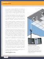
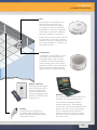
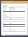
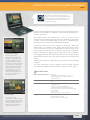
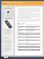
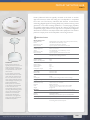
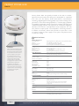
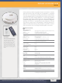
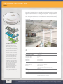
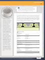
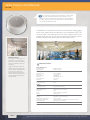
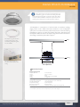
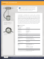
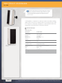
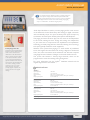
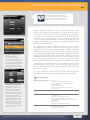
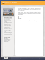
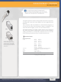
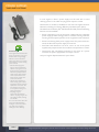
PRODUCT CATALOGUE
SOUND MASKING
PAGING
MUSIC
Download Specifications
from www.logison.com
table of contents
Overview
• A Trusted Provider . . . . . . . . . . . . . . . . . . . . . . . . . . . . . . . . . . . 2
• A Complete Solution. . . . . . . . . . . . . . . . . . . . . . . . . . . . . . . . . . 3
• Small Zones, Unbeatable Performance . . . . . . . . . . . . . . . . . . . . 4
Components . . . . . . . . . . . . . . . . . . . . . . . . . . . . . . . . . . . . . . . . . 5-24
Control
• Network Control Panel . . . . . . . . . . . . . . . . . . . . . . . . . . . . . 5-6
• Acoustic Network Manager Software . . . . . . . . . . . . . . . . . . . . . 7
• Programmable Keypad + Remote . . . . . . . . . . . . . . . . . . . . . . . . 8
Hubs
• Primary Network Hub . . . . . . . . . . . . . . . . . . . . . . . . . . . . . . . . 9
• Primary Power Hub . . . . . . . . . . . . . . . . . . . . . . . . . . . . . . . . . . 10
• Primary Accessory Hub . . . . . . . . . . . . . . . . . . . . . . . . . . . . . . . 11
• Secondary Network Hub . . . . . . . . . . . . . . . . . . . . . . . . . . . . . 12
Loudspeakers
• Loudspeaker . . . . . . . . . . . . . . . . . . . . . . . . . . . . . . . . . . . . . . . 13
• Open Ceiling Loudspeaker . . . . . . . . . . . . . . . . . . . . . . . . . . . . 14
• Ceiling Mount Loudspeaker . . . . . . . . . . . . . . . . . . . . . . . . . . . 15
• Chicago Loudspeaker . . . . . . . . . . . . . . . . . . . . . . . . . . . . . . . . 16
• Low Profile Loudspeaker . . . . . . . . . . . . . . . . . . . . . . . . . . . . . 17.
• Wall Mount Loudspeaker . . . . . . . . . . . . . . . . . . . . . . . . . . . . . 18
Paging & Music
• Audio Input Modules . . . . . . . . . . . . . . . . . . . . . . . . . . . . . . . . . 19
• Page Director Software. . . . . . . . . . . . . . . . . . . . . . . . . . . . . . . 20
Security
• Acoustic Network Supervisor Software . . . . . . . . . . . . . . . . . . 21
• Relay Output Module . . . . . . . . . . . . . . . . . . . . . . . . . . . . . . . . 22
Cabling
• Cable Assemblies + Couplers . . . . . . . . . . . . . . . . . . . . . . . . . . 23
Power
• Power Supplies . . . . . . . . . . . . . . . . . . . . . . . . . . . . . . . . . . . . . 24
PAGE: 1
OVERVIEW
A TRUSTED PROVIDER
Our company has been dedicated to the design and
manufacture of sound masking systems for over thirty
years. Our products are available globally and installed
in many hundreds of millions of square feet for clients
ranging in size from small business to Fortune 500.
In 2003, we revolutionized the industry when we launched
the world’s first networked sound masking, paging and
music system: the LogiSon® Acoustic Network. It’s
now a recognized leader that has earned over sixteen
awards for innovation, performance and ease of use.
With our length and breadth of experience in this field,
we know that flexibility is the key to a successful sound
masking implementation. That’s because it isn’t enough
to introduce just any sound into your space. It has to
be the right sound, in the right place, at the right time.
The LogiSon Acoustic Network provides this superior
level of acoustic control and puts it at your fingertips.
This elegantly engineered solution is suitable for projects of
any size and complexity. A variety of loudspeaker designs,
small zones and precise control over industry-leading
functions allow the system to be customized for the
unique conditions presented by each installation. It also
has paging and music capabilities, eliminating the need
for a separate system. Networked control of settings
and zones means adjustments can be made in minutes
following any organizational or structural changes.
Our representatives provide a complete range of
professional services and highly responsive technical
support. They design, tune and program the LogiSon
Acoustic Network, either independently or together with
your acoustical consultant.The system can be installed by
our representative’s in-house technicians, a third party
or your own electrical or audio contractor. If necessary,
it can easily be expanded or relocated in the future.
To find the LogiSon Representative nearest you or to
download the spec, visit our website:
www.logison.com
PAGE: 2
Network Control Panel
The Network Control Panel can be
mounted on a wall or in an equipment
closet. Users can manage the system’s
settings and zones from this central
location. If paging or background music are
needed, simply add an Audio Input Module
to the panel and connect a source, such as
a telephone system.
OVERVIEW
A COMPLETE SOLUTION
Hub
Primary Hubs are connected to the
Network Control Panel in series.
This component lets users program
the zoning and output for individual
loudspeakers. It also offers multiplexed
audio without the need for additional
generators, amplifiers or equalizers.
If desired, up to two Secondary Hubs can
be connected to each Primary Hub and
replicate its settings, increasing zone size
from one loudspeaker to a maximum of
three (225 to 675 ft2).
Loudspeaker
A loudspeaker is suspended from each
hub. Though usually located above a
suspended ceiling, a range of models
is available to accommodate different
needs, including open or hard ceilings.
Regardless of which one is selected, the
system’s backbone is always the same
high-performance LogiSon technology.
Keypad + Remote
The Programmable Keypad
and accompanying remote
provide occupants with
on-demand adjustment of
masking and paging settings,
ideal for private offices and
meeting rooms.
Cabling
Wiring consists of a single line of
low-voltage cable. However, zoning is
digital, not hardwired, allowing changes
to be made in minutes.
Software
The LogiSon Acoustic Network offers both
hardware- and software-based control.
Acoustic Network Manager Software
provides multi-floor or whole-building
control from one PC location. Page Director
Software lets users create custom paging
zones as required. Acoustic Network
Supervisor Software monitors the system
and sends an email to specified recipients
if an issue occurs.
PAGE: 3
OVERVIEW
SMALL ZONES, UNBEATABLE PERFORMANCE
22,500
128.6
11,250
64.3
5,625
32.1
1,800
10.3
•Aecom
•Agilent Technologies
•Bank of New York
•Capital One
•CB Richard Ellis
•CIBC
ft2
•CNN
•Cushman & Wakefield
•DaimlerChrysler
•Deloitte
•Ernst & Young
•Franklin Templeton
•GlaxoSmithKline
•Goodwill
•Hanesbrands
•Hilton
•Honda
•IBM
•Jones Lang LaSalle
•Kinross Gold
•Kraft
•Manulife Financial
•Marshall Macklin Monaghan
•Microsoft
•MillerCoors
•Modesto Memorial
•Nokia
•Pentair
•Polo Ralph Lauren
•PricewaterhouseCoopers
•Procter & Gamble
•Rabobank
•Royal Bank of Canada
•Shell
•Siemens
•Smith & Nephew
•Sony Ericsson
•Standard Life
•Target
•TELUS
•The Hartford
•Time Warner
•Towers Watson
•Tribeca Grand
•US Navy
•Volksbank
•Wachovia-Wells Fargo
•Xstrata
PAGE: 4
3.9
675
1.3
225
1
3
(175 ft2 per person)
•A.C. Nielsen
Average Number of Occupants per Zone
Partial Client List
8
25
50
100
Loudspeakers per Adjustment Zone
Any masking system will introduce a sound into your facility, but the
level of speech privacy, noise control and comfort you’ll achieve depends
on the size of its adjustment zones and the degree of control offered
within each one.
The LogiSon Acoustic Network provides the smallest zones (1 to 3
loudspeakers) with the finest adjustments: 100 volume steps in 0.5
dBA increments and 1/3-octave frequency control within each one.
The masking sound can be tuned to local conditions, ensuring that it’s
comfortable and effective across your entire space. And because control
is networked, this level of performance is also easy to maintain.
When a masking system’s adjustment zones are larger, numerous
loudspeakers are set to the same volume and frequency, but the sound
fluctuates across the space as it interacts with elements of the workplace
design. Because you can’t make precise changes in specific areas, you
have to set each zone to a level that’s merely best on average.
Some large-zoned systems try to address this problem by providing audio
transformers at each loudspeaker, but they only offer coarse volume
adjustments and none for frequency. Others direct their loudspeakers
downward in the mistaken belief that the factors influencing the sound
are thereby avoided. In reality, they simply don’t provide the control
needed to give you the best result.
The graph above shows the number of people who would be affected if
large zones forced you to choose between comfort and performance.
If you had to increase the volume to improve the system’s effectiveness
for the occupants in one area, it would be too loud for others. If you
lowered it, you’d sacrifice speech privacy and noise control. This pattern
would repeat at unpredictable points across your space.
You can usually expect a 10 percent reduction in performance for each
decibel below the target masking volume. Yet, some systems allow as
much as 4 to 6 dB variation.
Don’t risk your system’s performance. Choose a custom fit.
Network Control Panel
NCP-2
A sound masking system’s quality
and durability depend on its ability to
adapt to changes as much as on its material
construction. Networked control makes
future adjustments quick and easy because
changes can be made without physically
accessing the components or altering the
cabling. Such a high degree of flexibility
maximizes the system’s effectiveness and
occupant comfort, helping safeguard your
most valuable investment: employees.
Security
The LogiSon Acoustic Network
is secured using both physical
and electronic methods.
The Network Control Panel is
small and can easily be located
within a secure space. Cabling
connections are made inside the
enclosure. A key is required to
open the door and access the
keypad. A password is needed to
change the settings. There are no
physical controls on the hubs
or loudspeakers.
The network upstream from
the panel is open. However,
128-bit AES encryption ensures
that commands are unreadable
whether transmitted to the panel
by wired or wireless connection,
providing further protection
from unauthorized access.
Downstream, the network
is standard RS-485, which is
commonly used in building
automation.
The panel also monitors system
performance. If a Relay Output
Module is installed, it can be
connected to warning lights,
sirens or a third party security
system to immediately alert the
administrator to any issues. The
administrator can also elect to
receive email notification via the
Acoustic Network Supervisor
Software.
For more information about
the LogiSon Acoustic Network’s
security features, see the Acoustic
Network Supervisor Software and
Relay Output Module sections of
this catalogue or speak to your
LogiSon Representative.
The Network Control Panel can be wall-mounted within a room
or closet. It provides the functionality of numerous rack-mounted
components, reducing the costs, energy and space needed for equipment.
The panel allows the administrator to establish timer, paging and keypad
zones. There are no restrictions on the size of each type of zone and
they can be non-contiguous. The administrator can also set the volume
and equalizer levels for masking and paging, program ramp-up and
timer schedules, select paging channels, and create user limits for each
Programmable Keypad. The panel uses non-volatile memory so that
these settings are preserved in the event of a power failure.
Commands can be sent to one, a group or all Primary Hubs on the
system. Panels can be networked together so that the administrator can
manage several floors, an entire building or campus from one location.
They can also be linked to third party control systems. Changes can be
made in minutes following renovations, moving furniture or personnel,
keeping the system performing at optimal levels throughout its lifecycle.
Paging and music are provided simply by adding one or more Audio
Input Modules to the panel and connecting a source such as a telephone
system or MP3 player. The panel also features a priority page input that
allows temporary settings to be implemented in emergencies.
The panel’s calendar-based timer utility allows the administrator to
schedule changes in the sound masking volume to match expected
occupancy levels. Each panel offers nine timer zones. The administrator
can establish a different schedule for each zone and each day of the
week, with up to nine volume changes per day. These changes are made
at a gradual, user-defined rate so as not to call occupants’ attention to
them. The administrator can also program unique schedules for up to 30
individual dates, such as holidays. The panel adjusts for daylight saving time.
There is also an introductory ramp-up feature for retrofit installations,
which progressively increases the sound masking volume over a period of
up to 15 days, allowing occupants to acclimatize to their new acoustical
conditions.The administrator can program the ramp-up period to begin on
a defined date. A unique version can be established for each timer zone.
For more information, see the LogiSon® NCP-2 User Manual.
A LogiSon Representative will design the system and select the components. Technical specifications are subject to change without notice.
PAGE: 5
Network Control Panel
NCP-2
SPECIFICATIONS
Control Performance
Network initialization, masking, paging, timer, keypad settings, zoning, paging/music inputs, system monitoring and diagnostics
Masking Performance
Volume 35 to 85 dBA in 0.5 dBA steps + mute
Equalization (w/ PC) 1/3-octave, 23 bands, 63 to 10,000 Hz
Preset Contours 50 preset options; customization of each band
Paging Performance
Audio Inputs
Zone Configuration
Volume
Equalization (w/ PC)
Preset Contours
3, any combination of auxiliary, telephone and microphone
Zone 1, 2, 3 or none; unlimited zones with Page Director Software
35 to 85 dBA @ 1 m in 0.5 dBA steps + mute
1/1-octave, 8 bands
50 preset options; customization of each band
Timer Performance
Zone Number
Zone Size
Scheduling
Volume Changes per Day
Volume Increments
Rate of Change
Exception Schedules
Delayed Start Feature
Ramp Up Feature
Daylight Savings Adjustment
Up to 9
Unrestricted
Unique schedule for each day
Up to 9
0.5 dBA steps
0 to 9 minutes per volume increment
Up to 30 dates, 3 user-defined schedules
Yes
Up to 15 days, user-defined schedule in 0.5 or 1 dBA steps
Yes
Components per Panel
Max. Number of Components 125 per panel
Max. Number of Loudspeakers 375 per panel
Network Type
Upstream from Panel Open; protected with 128-bit AES encryption
Downstream from Panel Closed; standard RS-485
Connections
Power Input
Network Output
Ethernet Connection
Audio Inputs
Priority Page
3-pin, screw terminal
6-pin
10 Base-T RJ-45
3-pin, screw terminal x 3
2-pin, screw terminal
Power
Input
Output
Consumption
Ground
Relay Outputs
30 Vdc
30 Vdc
Maximum 12 W
Earth ground
2-pin, screw terminal x 2
Battery
Size 1/2 AA
Voltage 3.6 V
Life Expectancy 10 years
Physical Specifications
Dimensions (W x H x D)
Enclosure
Color
Weight
Keypad
Display
28 x 23 x 7.6 cm; 11 x 9 x 3 inches
Steel with powdercoat finish
Charcoal grey
2 kg; 5 lbs
20-key membrane panel
4 x 20 backlit LCD
Mounting
4 keyhole mounting positions
Security
Physical Key-lock enclosure
Electronic Password required to access settings, 3 levels
Warranty
5 years; see LogiSon® Product Warranty for details
Certifications Meets UL, FCC and CE standards; RoHS compliant
PAGE: 6
A LogiSon Representative will design the system and select the components. Technical specifications are subject to change without notice.
ACOUSTIC NETWORK MANAGER SOFTWARE
ANM
This desktop icon launches the software. The
laptop to the left shows the Masking Equalization
Screen. From this screen, the administrator can set
the masking volume and contour, and mute the
masking and/or paging.
Acoustic Network Manager can be used to control the LogiSon Acoustic
Network when linked to a Network Control Panel via Ethernet or
wireless connection.
This software gives the administrator a level of control that is
unsurpassed in the industry.The attractive user interface is configurable
to show or hide functionality based on the user or installation type.
Communication is protected by 128-bit AES encryption.
Control Panel Screen
This screen allows the
administrator to configure the
software to communicate with
the panels, initialize the system,
upload and download settings
between the software and panels,
save and retrieve setup files. The
Security and Components tabs
available from this screen allow
the administrator to set user
access levels and passwords,
establish functional alarms, name
and group components, check
their status and more.
Commands can be sent to one, a group or all Primary Hubs. The
administrator can establish timer, paging and keypad zones. There
are no restrictions on the size of each type of zone and they can be
non-contiguous.The administrator can also set the volume and equalizer
levels for masking and paging, program ramp-up and timer schedules,
select paging channels, and create user limits for each Programmable
Keypad. Hub indicators show hub types, hardware status, volume and
muting.
Settings can be saved to an electronic file or printed for record-keeping
purposes.
For more information, see the LogiSon® Acoustic Network Manager
User Manual. The application also includes a help file and user guide.
SPECIFICATIONS
Supported Operating Systems • Windows 7
• Windows Vista with Service Pack 2 or later
• Windows XP (x86 Home or Professional Edition)
with Service Pack 3
Supported Architectures
• X86
•X64
Hardware Requirements
• Computer with 1 GHz or faster processor with
1 GB RAM or more
•Graphics parts supporting WDDM drivers
(Windows Display Driver Model) recommended
• Minimum disk space (Microsoft components/Installation):
X86 – 850 MB
X64 – 2 GB
•Disk space (LogiSon components): 20 MB
Timer Screen
From this screen, the
administrator can set timer zones,
navigate between zones, program
each day’s schedule, set exception
dates and schedules, set the
daylight savings adjustment and
program ramp-up profiles.
Prerequisites
• Windows Installer 3.1 or later
•Internet Explorer 6.0 or later
• Microsoft .NET Framework 4 or later
A LogiSon Representative will design the system and select the components. Technical specifications are subject to change without notice.
PAGE: 7
PROGRAMMABLE KEYPAD + REMOTE
PK-1, PKR-1
The Programmable Keypad is installed in a standard single-gang wall box
using a white, Decora-style faceplate. It provides occupant control of the
sound masking and paging settings in private offices and meeting rooms,
or anywhere else there is a need for individual control. Each Network
Control Panel supports up to 58 keypad zones.
An administrator defines what area each keypad controls, the functions
it offers and the degree to which occupants can change those functions.
The occupant can then customize the room’s settings within those
parameters. For example, they may be able to increase or decrease the
sound masking and/or paging volume, mute the sound masking and/or
paging, and/or change the paging channel.
The administrator also sets the keypad’s default settings. The keypad
can be manually restored to these settings or set to do so automatically
after a defined period of time or at a particular time of day.
SPECIFICATIONS
Remote Control
The keypad also features an
infrared remote control receiver,
enabling the user to adjust the
settings using the Programmable
Keypad Remote (PKR-1). This
feature can be disabled in
high-security applications.
User Instructions
The Programmable Keypad is
easy to use.
To activate it, press any key. If the
desired function is not currently
highlighted, press the Select key
to choose either Masking or
Paging. The screen displays the
current setting for that function.
To increase or decrease the
volume, press the + or - key.
To mute the function, press the
Mute key. The screen displays
two dashes. To un-mute, press
the Mute key again.
To change the paging channel,
press the Select key until the
screen displays a C. To move to
another channel, press the +
or - key.
PAGE: 8
Control Performance
Masking and paging volume control, masking and paging mute, paging channel selection, remote control receiver enable/disable
Masking Performance
Volume Adjustment Range
Volume Restriction
Function Restriction
99 step range in 0.5 dBA steps + mute
Administrator defines minimum and maximum
Administrator enables or disables functions
Paging Performance
Volume Adjustment Range
Volume Restriction
Function Restriction
Paging Channel Selection
99 step range in 0.5 dBA steps + mute
Administrator defines minimum and maximum
Administrator enables or disables functions
Zone 1, 2, 3 or none
Connections
Network In/Out
6-pin
Power
Input
Consumption
30 Vdc
Maximum 6 W
Zoning
MethodElectronically zoned using Network Control Panel or Acoustic
Network Manager Software
Zone Size
No limit
Physical Specifications
Dimensions (W x H x D)
4 x 10.4 x 4.6 cm; 1.58 x 4.1 x 1.825 inches
ColorWhite
Weight
120 g; 4.2 oz
Display
2-digit LED
Keypad
4-key membrane panel
Remote Control
Remote Receiver
Function Restriction
Infrared remote control receiver for use with PKR-1
Administrator enables or disables function
Mounting
Single-gang wall box with white, Decora-style faceplate
Security
Function Restrictions
See restrictions noted above
Warranty
5 years: see LogiSon® Product Warranty for details
Certifications
Meets UL, FCC and CE standards; RoHS compliant
A LogiSon Representative will design the system and select the components. Technical specifications are subject to change without notice.
PRIMARY NETWORK HUB
PNH-2
Primary Network Hubs are typically mounted to the deck or another
approved structure within the ceiling and a loudspeaker is suspended
from each one. The Primary Network Hub features communication
technology, Digital Signal Processing (DSP) truly random masking sound
generation, a 1/3-octave masking equalizer, a 1/1-octave paging equalizer,
an amplifier, independent volume controls for masking and paging, and
multiplexed paging selection. This high level of component integration
eliminates the need for centrally-located audio equipment. The hub also
performs unique power and loudspeaker monitoring functions.
SPECIFICATIONS
Masking Performance
Sound Generation
Volume
Equalization (w/ PC)
Preset Contours
Digital Signal Processor (DSP), truly random (nondeterministic)
35 to 85 dBA in 0.5 dBA steps + mute
1/3-octave, 23 bands, 63 to 10,000 Hz
50 preset options; customization of each band
Paging Performance
Zone Configuration
Volume
Equalization (w/ PC)
Preset Contours
Zone 1, 2, 3 or none
35 to 85 dBA @ 1 m in 0.5 dBA steps + mute
1/1-octave, 8 bands
50 preset options; customization of each band
Timer PerformanceZoning and events set using Network Control Panel or
Acoustic Network Manager Software
Installation
Primary Network Hubs are
typically mounted to the deck or
another approved structure
within the ceiling. A loudspeaker
is suspended from each one, as
shown above.
In open ceilings, an attractive
braided steel cable can be used
rather than the standard chain.
For more information, see the
Open Ceiling Loudspeaker section
of this catalogue or speak to your
LogiSon Representative.
Primary Hubs are connected
to the Network Control Panel
in series and each one is
automatically assigned a unique
operating address during system
start up. The panel uses these
addresses to communicate
with the hubs, allowing the
administrator to program the
zoning and output variables for
individual loudspeakers.
Components per Hub
Number of SNH-1
Number of Loudspeakers
0 to 2
1 to 3
Connections
Network Input
Network Output
SNH Output
Loudspeaker Output
6-pin
6-pin
2-pin x 2
2-pin
Cabling
PNH to PNH
PNH to SNH
CA6 series cable
CA2 series cable
Power
Input
Consumption
30 Vdc
3.6 W at typical settings; 6.4 W at maximum settings
Integrated Amplifier
5W
Physical Specifications
Dimensions (W x H)
13.0 x 4.5 cm; 5.1 x 1.75 inches
Enclosure
Plenum-rated resin
ColorOff-white or charcoal grey; custom colors available
* White available for use with LA-1OP (not plenum rated)
Weight
0.2 kg; 0.4 lb
MountingFlexible mounting options; see LogiSon® Installation Manual
Security
Physical
Electronic
No physical controls
Monitoring of communication, power and loudspeakers
Warranty
5 years; see LogiSon® Product Warranty for details
CertificationsMeets UL, FCC and CE standards and is approved for use in
air-handling plenums; RoHS compliant
A LogiSon Representative will design the system and select the components. Technical specifications are subject to change without notice.
PAGE: 9
PRIMARY POWER HUB
PNH-2P
Primary Power Hubs are typically mounted to the deck or another
approved structure within the ceiling and a loudspeaker is suspended
from each one. The Primary Power Hub features communication
technology, Digital Signal Processing (DSP) truly random masking sound
generation, a 1/3-octave masking equalizer, a 1/1-octave paging equalizer,
an amplifier, independent volume controls for masking and paging, and
multiplexed paging selection. This high level of component integration
eliminates the need for centrally-located audio equipment. The hub
also performs unique power and loudspeaker monitoring functions.
In addition, the Primary Power Hub provides an input that is used
to connect a Class 2 power supply to the system with plenum-rated,
2-conductor cabling.
SPECIFICATIONS
Installation
While otherwise identical to the
Primary Network Hub (PNH-2),
the Primary Power Hub provides
an input that is used to connect
a power supply to the system.
According to codes in most
regions, a Class 2 power supply
must be used with a sound
masking system or the cable
carrying power requires conduit.
Several Class 2 options are
available for use with the
LogiSon Acoustic Network. For
more information, see the Power
Supplies section of this catalogue
or speak to your LogiSon
Representative.
Masking Performance
Sound Generation
Volume
Equalization (w/ PC)
Preset Contours
Digital Signal Processor (DSP), truly random (nondeterministic)
35 to 85 dBA in 0.5 dBA steps + mute
1/3-octave, 23 bands, 63 to 10,000 Hz
50 preset options; customization of each band
Paging Performance
Zone Configuration
Volume
Equalization (w/ PC)
Preset Contours
Zone 1, 2, 3 or none
35 to 85 dBA @ 1 m in 0.5 dBA steps + mute
1/1-octave, 8 bands
50 preset options; customization of each band
Timer Performance Zoning and events set using Network Control Panel or
Acoustic Network Manager Software
Components per Hub
Number of SNH-1
Number of Loudspeakers
0 to 2
1 to 3
Connections
Power Input
Network Input
Network Output
SNH Output
Loudspeaker Output
2-pin
6-pin
6-pin
2-pin x 2
2-pin
Cabling
PNH to PNH
PNH to SNH
CA6 series cable
CA2 series cable
Power
Input
Consumption
30 Vdc
3.6 W at typical settings; 6.4 W at maximum settings
Integrated Amplifier
5W
Physical Specifications
Dimensions (W x H)
13.0 x 4.5 cm; 5.1 x 1.75 inches
Enclosure
Plenum-rated resin
ColorOff-white or charcoal grey; custom colors available
* White available for use with LA-1OP (not plenum rated)
Weight
0.2 kg; 0.4 lb
MountingFlexible mounting options; see LogiSon® Installation Manual
PAGE: 10
Security
Physical
Electronic
No physical controls
Monitoring of communication, power and loudspeakers
Warranty
5 years; see LogiSon® Product Warranty for details
Certifications
Meets UL, FCC and CE standards and is approved for use in
air-handling plenums; RoHS compliant
A LogiSon Representative will design the system and select the components. Technical specifications are subject to change without notice.
PRIMARY ACCESSORY HUB
PNH-2A
Primary Accessory Hubs are typically mounted to the deck or another
approved structure within the ceiling and a loudspeaker is suspended
from each one. The Primary Accessory Hub features communication
technology, Digital Signal Processing (DSP) truly random masking sound
generation, a 1/3-octave masking equalizer, a 1/1-octave paging equalizer,
an amplifier, independent volume controls for masking and paging, and
multiplexed paging selection. This high level of component integration
eliminates the need for centrally-located audio equipment. The hub
also performs unique power and loudspeaker monitoring functions. In
addition, the Primary Accessory Hub provides an input that is used to
attach accessories such as the Programmable Keypad to the system.
SPECIFICATIONS
Accessories
While otherwise identical to the
Primary Network Hub (PNH-2),
the Primary Accessory Hub
provides an input that is used to
attach accessories such as the
Programmable Keypad (PK-1) to
the system. The keypad is shown
together with the Programmable
Keypad Remote Control (PKR-1)
above.
Masking Performance
Sound Generation
Volume
Equalization (w/ PC)
Preset Contours
Digital Signal Processor (DSP), truly random (nondeterministic)
35 to 85 dBA in 0.5 dBA steps + mute
1/3-octave, 23 bands, 63 to 10,000 Hz
50 preset options; customization of each band
Paging Performance
Zone Configuration
Volume
Equalization (w/ PC)
Preset Contours
Zone 1, 2, 3 or none
35 to 85 dBA @ 1 m in 0.5 dBA steps + mute
1/1-octave, 8 bands,
50 preset options; customization of each band
Timer PerformanceZoning and events set using Network Control Panel or
Acoustic Network Manager Software
Components per Hub
Number of SNH-1
Number of Loudspeakers
0 to 2
1 to 3
Connections
Accessory Input
Network Input
Network Output
SNH Output
Loudspeaker Output
6-pin
6-pin
6-pin
2-pin x 2
2-pin
Cabling
PNH to PNH
PNH to SNH
CA6 series cable
CA2 series cable
Power
Input
Consumption
30 Vdc
3.6 W at typical settings; 6.4 W at maximum settings
Integrated Amplifier
5W
Physical Specifications
Dimensions (W x H)
13.0 x 4.5 cm; 5.1 x 1.75 inches
Enclosure
Plenum-rated resin
ColorOff-white or charcoal grey; custom colors available
* White available for use with LA-1OP (not plenum rated)
Weight
0.2 kg; 0.4 lb
MountingFlexible mounting options; see LogiSon® Installation Manual
Security
Physical
Electronic
No physical controls
Monitoring of communication, power and loudspeakers
Warranty
5 years; see LogiSon® Product Warranty for details
Certifications
Meets UL, FCC and CE standards and is approved for use in
air-handling plenums; RoHS compliant
A LogiSon Representative will design the system and select the components. Technical specifications are subject to change without notice.
PAGE: 11
SECONDARY NETWORK HUB
SNH-1
Secondary Network Hubs are typically mounted to the deck or another
approved structure within the ceiling. A loudspeaker is suspended from
each one. Up to two of these hubs can be connected to each Primary
Hub, offering zones that are 1 to 3 loudspeakers in size. Each Secondary
Network Hub replicates the settings of the Primary Hub to which it is
connected.
Small Zones & Fine Control
Acoustic conditions and occupant
needs are different for private
offices, meeting rooms, corridors
and reception areas, as well as
across open plans. A sound masking
system’s ability to deal with these
differences is determined by the
size of its adjustment zones as
well as the volume and frequency
control it provides within each one.
Up to two Secondary Network
Hubs can be connected to each
Primary Hub, making the LogiSon
Acoustic Network’s adjustment
zones between 1 and 3
loudspeakers in size (225 to 675
ft2). Each zone offers 100 volume
steps in 0.5 dBA increments and
1/3-octave frequency control.
This small zone size and fine
control over settings allows the
LogiSon Acoustic Network’s
masking sound to be tuned
to accommodate local needs,
ensuring that it’s both effective and
unobtrusive across the entire space.
PAGE: 12
Hubs and loudspeakers suspended in an open ceiling.
SPECIFICATIONS
Output Performance Masking, paging and timer inherited from Primary Hub
Components per Hub
1 loudspeaker
Connections
Signal Input / Output
Loudspeaker Output
2-pin x 2
2-pin
Cabling
PNH to SNH
SNH to SNH
CA6 series cable
CA2 series cable
Power
0W
Physical Specifications
Dimensions (W x H)
13.0 x 4.5 cm; 5.1 x 1.75 inches
Enclosure
Plenum-rated resin
ColorOff-white or charcoal grey; custom colors available
* White available for use with LA-1OP (not plenum rated)
Weight
0.2 kg; 0.4 lb
Mounting
Flexible mounting options; see LogiSon® Installation Manual
Security
No physical controls
Warranty
5 years; see LogiSon® Product Warranty for details
Certifications
Meets UL, FCC and CE standards and is approved for use in
air-handling plenums; RoHS compliant
A LogiSon Representative will design the system and select the components. Technical specifications are subject to change without notice.
LOUDSPEAKER
LA-1
The most common and best-performing loudspeaker is
in-ceiling and upward-facing. Wall-mounted, downward-facing,
under-floor and desktop models are useful in situations where it is
impossible to access the ceiling or suspend anything in it. See the
appropriate sections of this catalogue for more information.
Loudspeaker Installation
The LogiSon Acoustic Network
loudspeakers are typically installed
upward-facing, above the ceiling
tiles. The indirect transmission
of the masking sound results in
broad, uniform coverage (see
diagram to the right).
The smallest zones (1 to 3
loudspeakers), as well as the
finest volume and equalization
controls (0.5 dBA steps;
1/3-octave), allow the system to
be easily adjusted to account for
local conditions above and below
the ceiling. In fact, we set the bar
for volume consistency in our
industry at ±0.5 dBA, ensuring
the masking sound is consistently
effective and unobtrusive.
Though sound masking
loudspeakers can also be
installed in a downward-facing
fashion (sometimes referred to
as ‘direct field’), we recommend
this only in very limited
circumstances. Downward-facing
loudspeakers are prone to
significant volume variations due
to a ‘spotlight’ effect.Volume
variations between loudspeakers
can call occupants’ attention
to the masking sound and
also reveal its source, which is
contrary to the user’s goals.
Furthermore, if the downwardfacing loudspeakers are installed
in an area with a suspended
ceiling, multiple cut-throughs are
required. In-plenum loudspeakers
are installed invisibly above the
ceiling tiles and will not damage
them.
A loudspeaker is suspended from a hub and used to broadcast masking,
paging and/or music. The LA-1 model is very flexible and used throughout
most LogiSon Acoustic Network installations. The custom clip allows
the length of chain to be adjusted without tools. Slack cable retracts into
the enclosure, ensuring tidy installation. The full-range driver provides
output exceeding the typical masking spectrum of 100 to 5,000 Hz,
including the lower frequencies needed for comfort.
SPECIFICATIONS
Audio Performance
Masking Output
Paging Output
87 dBA maximum
87 dBA maximum
Driver Specifications
Frequency Range
Dimension
Power Handling
Sensitivity
Magnet Structure
Impedance
90 to 10,500 Hz
10.1 cm; 4 inches
25 W (RMS)
88.6 dBA @ 1W / 1m
510 g; 18 oz
16 ohms
Connections
Loudspeaker Input
2-pin
Cabling
Loudspeaker to Hub
Integrated cable assembly
Physical Specifications
Dimensions (W x H)
16.5 x 9.0 cm; 6.5 x 3.5 inches
Enclosure
Plenum-rated resin
ColorOff-white or charcoal grey; custom colors available
Weight
0.95 kg; 1.9 lbs
Mounting
Method
Suspend from hub or from deck
Chain Length
61 cm; 24 inches
Chain Adjustment
Tool-free clip
Loudspeaker OrientationUpwards; tool-free reversibility to downwards if necessary
Cable Management
Slack retracts into enclosure
Warranty
Certifications
5 years; see LogiSon® Product Warranty for details
Meets UL, FCC and CE standards and is approved for use in
air-handling plenums; RoHS compliant
A LogiSon Representative will design the system and select the components. Technical specifications are subject to change without notice.
PAGE: 13
OPEN CEILING LOUDSPEAKER
LA-1OP
Its contemporary design and clean, single line of cable makes
the LogiSon Acoustic Network the best choice for open
ceilings. The white LA-1OP model easily blends in with the lighting
and other exposed components. White hubs are also available for
use with this loudspeaker model.
A loudspeaker is connected to a hub and used to broadcast masking, paging
and/or music. While otherwise identical to the Loudspeaker (LA-1), the
LA-1OP model is the preferred choice for open ceilings because of its
brighter finish. The user can also opt to suspend it from the hub with an
attractive braided steel cable rather than the standard chain.
Attractive Design
If the facility, or a percentage of it,
will feature an open ceiling, the
appearance of the sound masking
system’s loudspeakers should be
considered.
LogiSon components have been
designed with visible applications
in mind and will complement the
investment you make in your
facility’s appearance. The photos
above and to the right show open
ceiling installations featuring the
LA-1OP model.
Mark Trew © SHW Group.
SPECIFICATIONS
Audio Performance
Masking Output
Paging Output
87 dBA maximum
87 dBA maximum
Driver Specifications
Frequency Range
Dimension
Power Handling
Sensitivity
Magnet Structure
Impedance
90 to 10,500 Hz
10.1 cm; 4 inches
25 W (RMS)
88.6 dBA @ 1W / 1m
510 g; 18 oz
16 ohms
Connections
Loudspeaker Input
2-pin
Cabling
Loudspeaker to Hub
Integrated cable assembly
Physical Specifications
Dimensions (W x H)
16.5 x 9.0 cm; 6.5 x 3.5 inches
EnclosureResin
Color
White; custom colors available
Weight
0.95 kg; 1.9 lbs
Mounting
Method
Braided Steel Cable Length
Loudspeaker Orientation
Cable Management
Suspend from hub or from deck
61 cm; 24 inches
Upwards; tool-free reversibility to downwards if necessary
Slack retracts into enclosure
Warranty
5 years; see LogiSon® Product Warranty for details
Certifications
PAGE: 14
Meets UL, FCC and CE standards; RoHS compliant
A LogiSon Representative will design the system and select the components. Technical specifications are subject to change without notice.
CEILING MOUNT LOUDSPEAKER
LA-1CM
The LA-1CM model is used when the loudspeaker must
be installed in gypsum or another hard ceiling material. A
downward-facing loudspeaker (sometimes called ‘direct field’)
is only used when installation conditions require because the
masking sound’s dispersion and uniformity will be reduced.
A loudspeaker is connected to a hub and used to broadcast masking,
paging and/or music. While otherwise identical to the Loudspeaker
(LA-1), the LA-1CM model is the preferred choice for downward-facing
installation in gypsum or other hard ceilings. The hub is attached to the
loudspeaker and lowered into an adapter ring that has been mounted to
the ceiling. A steel back plate offers support.
The adapter ring pictured above
is white. Custom colors, with
coordinating loudspeaker grilles,
are also available.
Deck
Ceiling
The photo above shows the
LA-1CM model installed in the
ceiling.
Cut Through Diameter
17.2 cm (6.8 inches)
SPECIFICATIONS
Physical Specifications
Faceplate Diameter
22 cm; 8.7 inches
Depth
2.8 cm; 1.1 inches
MaterialResin
Color
White; custom colors available
Weight
0.1 kg; 0.2 lb
Mounting
Attachment to Loudspeaker
Cut-Through Diameter
Suspension to Ceiling
Bolt Size for Suspension
Backup Suspension
Lay-in (with option for screw attachment)
17.2 cm; 6.8 inches
3-point suspension
8-32 x 2.5 inches
Additional suspension option from d-ring on hub
Warranty
5 years; see LogiSon® Product Warranty for details
* For loudspeaker specifications, refer to the Loudspeaker (LA-1) section of this catalogue.
A LogiSon Representative will design the system and select the components. Technical specifications are subject to change without notice.
PAGE: 15
CHICAGO LOUDSPEAKER
LA-1CH
The Loudspeaker (LA-1) already meets UL 2043 Fire Test for
Heat and Visible Smoke Release for Discrete Products and Their
Accessories Installed in Air-Handling Spaces. The LA-1CH model –
dubbed the ‘Chicago Loudspeaker’ – is installed in regions where
building code requires conduit to be used in any case.
The Chicago Loudspeaker is
pictured above, connected to the
hub junction box with Flexible
Metal Tubing.
A loudspeaker is suspended from a hub and used to broadcast
masking, paging and/or music. The LA-1CH model and the junction
box used to house the hub were designed to meet Chicago’s stringent
requirements. The enclosure and junction box are made of steel. The
cabling is contained within Flexible Metal Tubing (FMT) listed for use in
plenums and other air handling spaces. Where it enters the enclosure,
this specialized conduit terminates in a one-piece zinc connector fitted
with a rubberized polymer gasket, forming the smoke-tight seal required
by the NEC. The junction box is also sealed. A flame retardant fabric
located below the speaker grille prevents the accumulation of dust.
SPECIFICATIONS
A hub shown inside the sealed
junction box.
Audio Performance
Masking Output
Paging Output
87 dBA maximum
87 dBA maximum
Driver Specifications
Frequency Range
Dimension
Power Handling
Sensitivity
Magnet Structure
Impedance
90 to 10,500 Hz
10.1 cm; 4 inches
25 W (RMS)
88.6 dBA @ 1W / 1m
510 g; 18 oz
16 ohms
Connections
Loudspeaker Input
2-pin
Cabling
Loudspeaker to Hub
Integrated cable assembly in FMT
Physical Specifications
Dimensions (W x H)
15.2 x 15.8 cm; 6 x 6.2 inches
EnclosureElectroplated steel housing, 26 gauge
Weight
1.52 kg; 3.36 lbs including FMT and chain
Mounting
Method
Chain Length
Loudspeaker Orientation
Suspend from hub
45.7 cm; 18 inches
Upwards facing
Junction Box for Hub
Dimensions (W x H)
20.3 x 6.6 cm; 8 x 2.6 inches
MaterialElectroplated steel housing, 26 gauge
Gasket
Neoprene / EPDM / SBR
Knockouts5 knockouts;
0.086 inches for ¾-inch conduit;
1.125 inches for 1-inch conduit
Weight
756 g; 1.6 lbs, not including hub
Warranty
Certifications
5 years; see LogiSon® Product Warranty for details
Meets UL, FCC and CE standards and is approved for use in
air-handling plenums; RoHS compliant
* For hub specifications, refer to the appropriate section(s) of this catalogue.
PAGE: 16
A LogiSon Representative will design the system and select the components. Technical specifications are subject to change without notice.
LOW PROFILE LOUDSPEAKER
LA-1LP
The LA-1LP model is designed for use in low-profile
plenum installations. However, it can also be used under
raised flooring.
A loudspeaker is connected to a hub and used to broadcast masking,
paging and/or music. The LA-1LP model has been engineered for
underfloor and low-profile plenum installations.
Four 3-inch, full-range drivers (100 to 8,000 Hz ± 6 dB) are mounted
at 90 degree angles for uniform 360° masking dispersion. The drivers
are directed 53 degrees from vertical in order to avoid the creation
of standing waves and maintain more localized sound distribution
compared to horizontally-directed drivers.
An overhead view of the
LA-1LP showing its four drivers,
plenum-rated cable connection
and central mounting hole.
Under Floor Installation
The LA-1LP can be installed in a
grid-like pattern beneath a raised
floor. However, because installing
in this location significantly
compromises a sound masking
system’s performance – and rules
out using the system for paging/
music distribution – it should
only be considered if the client
absolutely cannot install their
system in the ceiling space. If no
other option is available, only the
LogiSon Acoustic Network will
provide the tuning flexibility and
ease of future reconfiguration these
installation conditions demand.
The speaker is housed in a durable, sealed steel enclosure that may be
bolted directly to the ceiling or floor deck. In underfloor applications,
the loudspeaker may be secured to the raised floor support. Four rubber
feet prevent vibration from transmitting to the floor deck.
SPECIFICATIONS
Audio Performance
Masking Output
Paging Output
87 dBA maximum
87 dBA maximum
Driver Specifications
Frequency Range
Dimension
Power Handling
Sensitivity
Magnet Structure
Impedance
100 to 8,000 Hz ± 6 dB
7.6 cm; 3 inches
10 W (RMS)
84.2 dBA @ 1W / 1m
58 g; 2.05 oz
16 ohms
Connections
Loudspeaker Input
2-pin
Cabling
Loudspeaker to Hub
Integrated cable assembly
Physical Specifications
Dimensions (W x H)
21.6 x 8.1 cm; 8.5 x 3.2 inches
EnclosureMetal
ColorWhite
Weight
1.72 kg; 3.81 lbs
Mounting
Bolted directly to the ceiling or floor deck
Warranty
5 years; see LogiSon® Product Warranty for details
Certifications
Meets UL, FCC and CE standards and is approved for use in
air-handling plenums; RoHS compliant
A LogiSon Representative will design the system and select the components. Technical specifications are subject to change without notice.
PAGE: 17
WALL MOUNT LOUDSPEAKER
LA-1WM
The LA-1WM model can be used in locations such as atriums
where a suspended loudspeaker might be difficult to install
or awkward in appearance. A side view (left) shows the swivel
bracket that allows the loudspeaker to be positioned in the
desired direction.
A loudspeaker is connected to a hub and used to broadcast masking,
paging and/or music. The LA-1WM model can be mounted on the wall
in a vertical or horizontal orientation. A swivel bracket allows the
loudspeaker to be positioned in the desired direction.
SPECIFICATIONS
The loudspeaker shown from
the front.
Audio Performance
Masking Output
Paging Output
81 dBA maximum
81 dBA maximum
Driver Specifications
Frequency Range
Dimension
Power Handling
Sensitivity
Magnet Structure
Impedance
100 to 10,000 Hz
7.6 cm; 3 inches
10 W (RMS)
84.2 dBA @ 1W / 1m
58 g; 2.05 oz
16 ohms
Connections
Loudspeaker Input
2-pin
Cabling
Loudspeaker to Hub
Integrated cable assembly
Physical Specifications
Dimensions (W x H x L)
12 x 11 x 24.5 cm; 4.7 x 4.3 x 9.7 inches
Enclosure
Metal and plastic
ColorWhite
Weight
0.91 kg; 2 lb
Mounting
Swivel bracket for wall mounting
Warranty
5 years; see LogiSon® Product Warranty for details
Certifications
PAGE: 18
Meets UL, FCC and CE standards; RoHS compliant
A LogiSon Representative will design the system and select the components. Technical specifications are subject to change without notice.
AUDIO INPUT MODULES
AIM-2A, AIM-2M, AIM-2T
The LogiSon Acoustic Network is also a versatile paging and
music system. Simply install an Audio Input Module in the
Network Control Panel and connect a source, such as a telephone
or MP3 player. Clients can have areas with masking only, paging
only or a combination – all within a single system.
Audio Input Modules are used to connect paging and/or music sources
to the Network Control Panel. They offer analog to digital conversion
and automatically adjust for input sensitivity. Each panel accepts any
combination of three inputs: Auxiliary, Microphone and Telephone.
The paging and music functions play over the same set of loudspeakers
as the sound masking, but their zoning and settings are independent,
so you never have to compromise. The amplification and equalization
technology is already integrated into the hubs, reducing the cost, energy
and space typically needed for audio equipment.
Priority Page Override
The Network Control Panel also
features a priority page function,
which can be used for voice
clarification in all call situations.
When a priority signal is relayed
to the panel, it sets the volume
to a pre-programmed level and
plays the announcement over the
entire system. The administrator
can set the masking to either
continue to run or to mute
during this page. Once the
priority page is complete, the
system returns to its original
settings.
Whereas most systems limit paging to a small number of predefined
zones, the LogiSon Acoustic Network’s zoning is digital, not hardwired.
Users can create customized zones whenever and wherever required
using Page Director Software. Changes can be made within minutes.
The system also features a Priority Page Override, which can be
programmed to mute the masking during emergencies.
For more information, see the LogiSon® Installation Manual and the
LogiSon® Page Director User Manual.
SPECIFICATIONS
Auxiliary
Input Impedance
Input Level
Input Sensitivity
Gain
Frequency Response
100 kohm
10 V maximum
300 mV for maximum output
Maximum 20 dB, adjustable in thirty two 1 dB steps
20 to 10,000 Hz
Microphone
Input Impedance
Input Level
Input Sensitivity
Gain
Frequency Response
600 ohm
30 mV maximum
1 mV for maximum output
Maximum 70 dB, adjustable in thirty two 1 dB steps
20 to 10,000 Hz
Telephone
Input Impedance
Input Level
Input Sensitivity
Gain
Frequency Response
600 ohm
10 V maximum
300 mV for maximum output
Maximum 20 dB, adjustable in thirty two 1 dB steps
20 to 10,000 Hz
Warranty
Certifications
5 years; see LogiSon® Product Warranty for details
Meets UL, FCC and CE standards; RoHS compliant
A LogiSon Representative will design the system and select the components. Technical specifications are subject to change without notice.
PAGE: 19
PAGE DIRECTOR SOFTWARE
PD
This desktop icon launches the software. While
paging systems are usually limited to a small
number of hardwired zones, the LogiSon Acoustic
Network offers flexible paging and music options.
Paging Configuration Screen
This screen allows the administrator
to configure Page Director to
communicate with the LogiSon
Acoustic Network. Configuration
includes active Network Control
Panels, hub naming, active audio
inputs, and default page zones. To
assist the user, hubs can be identified
by a more meaningful name, one
that they will easily recognize. For
example, if Hub 3 is in room A101,
it can be named “A101.”
Page Director allows the user to create, alter or delete an unlimited
number of page zones on demand. Because of its function, this software
is typically installed at a reception desk. It is designed to work with
multiple Network Control Panels, allowing virtually unlimited control
over any number of floors or buildings.
Paging is possible at a single loudspeaker location or over any given
range of loudspeakers. It is also easy to create an ‘All Call’ zone for a
facility, floor or department.
The user can select the desired loudspeakers, name the zone and enter
a description for future reference (e.g. Meeting Room, Floor 1). They
can sort paging zones into user-defined categories and subcategories for
easy accessibility. The interface also provides a means to quickly search
for a predefined zone. The software offers backup and restore functions
for zones and settings.
The user can select one of three Audio Input Modules to use for each
page, such as a microphone. If only one device is available, the software
selects it by default.The user can manually end the page or set it to finish
automatically, after which the system returns to its default settings.
For more information, see the LogiSon® Page Director User Manual. The
application also includes a help file and user guide.
SPECIFICATIONS
User Control Screen
This screen allows users to
create custom page zones on
demand. Simply select the desired
hubs, name the zone and make
the announcement. Hubs can be
set to belong to any number of
paging zones.
Supported Operating Systems • Windows 7
• Windows Vista with Service Pack 2 or later
• Windows XP (x86 Home or Professional Edition)
with Service Pack 3
Supported Architectures
Hardware Requirements
• Computer with 1 GHz or faster processor with
1 GB RAM or more
•Graphics parts supporting WDDM drivers
(Windows Display Driver Model) recommended
•Minimum disk space (Microsoft components/Installation):
X86 – 850 MB
X64 – 2 GB
•Disk space (LogiSon components): 5 MB
Prerequisites
PAGE: 20
• X86
•X64
• Windows Installer 3.1 or later
•Internet Explorer 6.0 or later
• Microsoft .NET Framework 4 or later
A LogiSon Representative will design the system and select the components. Technical specifications are subject to change without notice.
ACOUSTIC NETWORK SUPERVISOR SOFTWARE
ANS
This desktop icon launches the software.
The Monitor Settings Screen (left) enables the
administrator to set the monitoring interval,
enable or disable notifications, and more.
Acoustic Network Supervisor runs as a Windows Service, which
monitors the LogiSon Acoustic Network to ensure that the system
is 100 percent operational 24/7. The administrator can configure it
to monitor only the Network Control Panel(s) or all of the system’s
components. If an issue occurs, the software sends an email so that
it can be quickly addressed. Because it monitors externally from the
LogiSon Acoustic Network hardware, a hardware failure will not impact
its ability to send these alerts.
Hardware Definition Screen
This screen allows the
administrator to configure
Acoustic Network Supervisor to
communicate with the Network
Control Panel(s) it will monitor. If
panels were previously defined in
the Acoustic Network Manager
Software, they can be imported.
The administrator defines the intervals at which the system should
be checked, from as often as every two minutes up to as long as
twenty-four hours. The administrator also defines to whom notification
should be sent if an event occurs – for example, to the facility manager,
IT personnel and the LogiSon Representative.The administrator can add
a unique name (e.g. facility name) to the email, providing a means of
identifying individual locations if it is sent to a remote recipient or one
who is monitoring several facilities or floors for various tenants. They
can also add vendor information to inform the recipient who to contact.
The software can be configured not to send emails in the event of client
network outages and can send a start-up message when monitoring
resumes. Alive notifications can be enabled to inform recipients that the
application is running.
For more information, see the LogiSon® Acoustic Network Supervisor
User Manual. The application also includes a help file and user guide.
SPECIFICATIONS
Notification Settings Screen
This screen allows the
administrator to enter the mail
server settings, authentication
options and message settings,
including the subject line, recipient
address(es), the priority setting
for the email and the facility
name. They can also enter vendor
information, which inserts the
LogiSon Representative’s contact
information into the email. If the
administrator does not elect to
copy them on the notifications,
they can be contacted directly by
the person notified.
Supported Operating Systems •Windows 7
•Windows Vista with Service Pack 2 or later
•Windows XP (x86 Home or Professional Edition)
with Service Pack 3
•Windows Server 2003 SP2
•Windows Server 2008, R2 SP1 (not supported on
Server Core Role)
Supported Architectures
•X86
•X64
Hardware Requirements
•Computer with 1 GHz or faster processor with
1 GB RAM or more
•Graphics parts supporting WDDM drivers
(Windows Display Driver Model) recommended
•Minimum disk space (Microsoft components/Installation):
X86 – 850 MB
X64 – 2 GB
•Disk space (LogiSon components): 5 MB
Prerequisites
• Windows Installer 3.1 or later
•Internet Explorer 6.0 or later
• Microsoft .NET Framework 4 or later
A LogiSon Representative will design the system and select the components. Technical specifications are subject to change without notice.
PAGE: 21
RELAY OUTPUT MODULE
ROM-2
The Relay Output Module is used to connect the Network Control
Panel to up to two external devices, such as warning lights, sirens and/
or a security system.
For more information about the LogiSon Acoustic Network’s
security features, see the Network Control Panel and Acoustic Network
Supervisor Software sections of this catalogue or speak to your LogiSon
Representative.
Additional Security Features
The LogiSon Acoustic Network
can be used to protect
verbal communications from
eavesdropping and electronic
surveillance.
SPECIFICATIONS
Relay Output
Rated Load
Warranty
0.5 A at 125 VAC; 1 A at 24 VDC
Certifications
5 years; see LogiSon® Product Warranty for details
Meets UL, FCC and CE standards; RoHS compliant
This benefit can be augmented
by connecting the system to
transducers that transfer the
masking sound to physical
structures such as windows,
doors, ducts, pipes and walls,
impeding the use of audio
surveillance equipment.
Each transducer’s volume and
frequency can be modified to
ensure that they are appropriate
for the surface to which it
is applied.
The randomness of the masking
sound makes it exceedingly
difficult to filter and the
components cannot be modified
to act as listening devices.
Applications Include
• R&D facilities
• Corporate boardrooms
• Government facilities
• Military facilities
• Police stations
• Military contractors
• Law firms
• Courts
• Temporary facilities
PAGE: 22
A LogiSon Representative will design the system and select the components. Technical specifications are subject to change without notice.
CABLE ASSEMBLIES + COUPLERS
CA2, CA6, CC2, CC6
The LogiSon Acoustic Network is installed without
hard-wiring timer, keypad, paging and music zones, because
all zones are software-generated. Minimal cabling ensures efficient
installation and a clean appearance in visible applications.
A single line of plenum-rated, low-voltage cable connects the components,
carrying power, control and audio signals across the LogiSon Acoustic
Network.
The 2-conductor cables are available in 5, 18, 25 and 50 foot lengths (1.5,
5.5, 7.6 and 15.2 meters). The 6-conductor cables are available in 5, 18,
25, 50 and 100 foot lengths (1.5, 5.5, 7.6, 15.2 and 30.4 meters).
CC2
All Cable Assemblies and Cable Couplers feature micro-connectors
that simply snap together, enabling quick, accurate and tidy installation.
Cabling connections are marked with embossed icons on the hubs.
Positive-locking mechanisms prevent accidental disconnection.
SPECIFICATIONS
CC6
Cable Couplers are used to
connect two Cable Assemblies
together when a longer length
is required. They are available in
both 2- (CC2) and 6-conductor
(CC6) sizes.
Physical Specifications
Lengths
CA2-55 ft; 1.5 m
CA2-18
18 ft; 5.5 m
CA2-25
25 ft; 7.6 m
CA2-50
50 ft; 15.2 m
CA6-5
5 ft; 1.5 m
CA6-18
18 ft; 5.5 m
CA6-25
25 ft; 7.6 m
CA6-50
50 ft; 15.2 m
CA6-100 100 ft; 30.4 m
Connectors2- and 6-pin over-molded micro-connectors featuring
orientation guides and positive-lock mechanism
Gauge
20 AWG
Material
Copper stranded
Color
White or charcoal grey
Warranty
Certifications
5 years; see LogiSon® Product Warranty for details
Meets UL, FCC and CE standards and is approved for use in
air-handling plenums; RoHS compliant
A LogiSon Representative will design the system and select the components. Technical specifications are subject to change without notice.
PAGE: 23
POWER SUPPLIES
THIRD PARTY OPTIONS
In most regions, a Class 2 power supply must be used with a sound
masking system or the cable carrying power requires conduit.
Several Class 2 models are available for use with the LogiSon Acoustic
Network, including a UL Energy Efficiency Certified option (PS-3).
Fail-Safe Power Solutions (FPS 120, FPS 250, FPS 500) with the following
features are also available:
• P
ower redundancy: If one of the power supplies fails, the redundant
power supply provides enough power to continue running a full load,
ensuring uninterrupted operation of the LogiSon Acoustic Network.
• P
ower load sharing: Each power supply shares the power load. As a
result, the life of each power supply is increased.
• A
utomatic fault detection: If an error occurs in one of the power
supplies, relay outputs detect the condition and open/close a contact.
Sustainability
The LogiSon Acoustic Network’s
energy consumption is very low:
less than that of a typical light
bulb for an area of 13,500 ft2.
• O
vercurrent and overvoltage protection: In the event of a power
overload, the power supply limits the output current.
Ask your LogiSon Representative for spec sheets.
Other green factors to consider
when selecting a sound masking
system include:
• Environmental programs:
Find out if the manufacturer
adheres to programs such as
the Restriction of Hazardous
Substances (RoHS) initiative,
which ensures that products
meet requirements for low
levels of heavy metals, such
as lead and cadmium.
• Lifecycle and maintenance:
Most masking systems have a
long lifespan and can easily be
expanded or relocated. Ask
how changes can be made
to the system’s settings and
zoning in the future.
• Recycling program:
Check if the manufacturer
offers a recycling program for
end-of-life products, ensuring
zero landfill.
For more information about the
impact of sustainable design
strategies on acoustics, ask for
our white paper Acoustical
Challenges in Green Buildings.
PAGE: 24
A LogiSon Representative will design the system and select the components. Technical specifications are subject to change without notice.
Your
Networked Solution
for Speech
and
[email protected]
Privacy
Noise Control
www.logison.com
1.866.LOGISON
Patents granted in Canada, Australia. Patents pending in U.S., Canada and other jurisdictions.
© 2012 K.R. Moeller Associates Ltd. LogiSon, AccuMask, Scamp, Archoustics and Acoustic Comfort are registered trademarks of 777388 Ontario Limited.