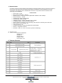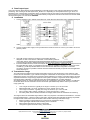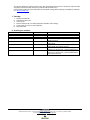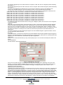
1
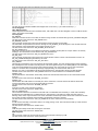
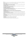
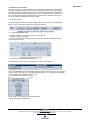
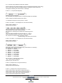
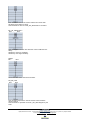
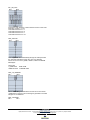
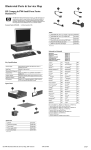
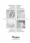
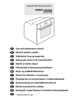
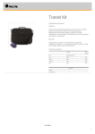
Autonomous digital sensors array in one device - basic elements of a wireless digital control systems and data acquaintance User manual SerGEn 2Bi(An) EnOcean Transceiver – Serial Gateway EnOcean RS232 bidirectional. version 4.4D. 17.10.2012. www.exesense.com Представитель в России – ATLAS Group, Москва, Дмитровское шоссе 100 стр. 2 phone +7 (495) 64-335-65 e-mail: [email protected], [email protected] www.atlasgroup.ru 1. General Notice The radio Transceiver module SerGEn 2 Bi operates as a gateway between sensors, actuators etc, based on the EnOcean radio technology and RS232 serial interface. All telegrams received flawlessly are output unchanged to the COM port. Thus, a bidirectional connection to any devices based on EnOcean radio technology could established. Technical data: Power supply 5 VDC Max current consumption – 200 mA Wireless protocol – EnOcean Frequency/Modulation 868MHz / ASK /125kbps Receiver sensivity - 96 dBm Transmit power below 10mW (5dBm) Transmit range 300m free field Hardware interface – RS232 Full-duplex, async, 9.6kbps Tx reliability feature Carrier sense before transmit Receiver features Sensitivity can be reduced by SW command or manually in the tied mode. Fast Tx power up from standby 2us Tx/Rx changeover 0.5u Modem functionality 6 bytes per telegram with acknowledge Antenna – integrated or external Protection – IP65, -20- +50 C, max rH 95 %( without condensing). 2. Data Format Baud rate: 9600 Baud Start bit (ST): 1 Data bits: 8 Stop bits (SP): 1 Parity (P): none Flow control: none 3. Telegram Structure www.exesense.com Представитель в России – ATLAS Group, Москва, Дмитровское шоссе 100 стр. 2 phone +7 (495) 64-335-65 e-mail: [email protected], [email protected] www.atlasgroup.ru 4. Data Output Input. Output from RS232. Each telegram received flawlessly is generally output on the COM port side without any further processing. The meaning of the data bytes DATA_BYTE0...3 is depending on the respective device type. Thus, it is described in the corresponding product data sheets. In Filtering mode the only tied ID could reached the RS232 output. Input to RS232. You could send two type of command Gateway configuration command and Transmit command. Detail command description you could find in APENDIX. 5. Installation 1. Connect interface to any desired serial COM port, serial cable max length 20m using shielded twisted pair cable. 2. Connect 5 VDC power supply to mini jack attached to serial connector or connect your cable to P3 on the gateway’s PCB. 3. Use TCM monitor software for receiving or transmitting EnOcean telegrams or refer to last version of EnOcean communication profile for using other devices supporting free programmed RS232 interfaces. You can use free WinEtel Communication Software ( please download it from http://www.enocean.com/en/download/ ) EnOcean WinEtel receives, sends and analyses EnOcean RF telegrams. Telegrams are displayed and can be logged with time stamp. In combination with tranceivers its possible to simulate e.g. sensors or switch modules (e.g. PTM 200). WinEtel allows to send and retrieve dedicated configuration commands (TCT/RCT). Further it is possible to extend the basic terminal functionality for specific use and application cases with Plug Ins. 4. 6. Transmission range The main factors that influence the system transmission range are type and location of the antennas of the receiver and the transmitter, type of terrain and degree of obstruction of the link path, sources of interference affecting the receiver, and “dead” spots caused by signal reflections from nearby conductive objects. Since the expected transmission range strongly depends on this system conditions, range tests should categorically be performed before notification of a particular range that will be attainable by a certain application. The following figures for expected transmission range are considered by using a PTM, a STM or a TCM radio transmitter device and the TCM radio receiver device with preinstalled whip antenna and may be used as a rough guide only: Line-of-sight connections: Typically 30 m range in corridors, up to 100 m in halls Plasterboard walls / dry wood: Typically 30 m range, through max. 5 walls Line-of-sight connections: Typically 30 m range in corridors, up to 100 m in halls Ferro concrete walls / ceilings: Typically 10 m range, through max. 1 ceiling Fire-safety walls, elevator shafts, staircases and supply areas should be considered as screening. The angle at which the transmitted signal hits the wall is very important. The effective wall thickness – and with it the signal attenuation – varies according to this angle. Signals should be transmitted as directly as possible through the wall. Wall niches should be avoided. Other factors restricting transmission range: Switch mounted on metal surfaces (up to 30% loss of transmission range) Hollow lightweight walls filled with insulating wool on metal foil False ceilings with panels of metal or carbon fibre Lead glass or glass with metal coating, steel furniture www.exesense.com Представитель в России – ATLAS Group, Москва, Дмитровское шоссе 100 стр. 2 phone +7 (495) 64-335-65 e-mail: [email protected], [email protected] www.atlasgroup.ru The distance between EnOcean receivers and other transmitting devices such as computers, audio and video equipment that also emit high-frequency signals should be at least 0.5 m A summarized application note to determine the transmission range within buildings is available as download from www.enocean.com 7. Package 1. 2. 3. 4. 5. 6. Gateway SerGEn 2Bi. Software and driver CD. User manual. External antenna with 2 m cable (Optional for SerGEn xxxAn design). Power supply unit 220=>5 VDC (Optional). Warrantee card. 8. Ordering art number. Art number Name Description SerGEn 2Bi SerGEn 2BiAn EnOcean-RS232 gateway bidirectional EnOcean-RS232 gateway bidirectional with external antenna. EnOcean-RS485 (point to point) gateway bidirectional EnOcean-RS485 (point to point) gateway bidirectional with external antenna. EnOcean-RS485 (with bus master topology, 32 gateways on the bus max.) gateway bidirectional. EnOcean-RS485 (with bus master topology, 32 gateways on the bus max.) gateway bidirectional with external antenna. SerGEn 4Bi SerGEn 4BiAn SerGEn 4BiB SerGEn 4BiBAn www.exesense.com Представитель в России – ATLAS Group, Москва, Дмитровское шоссе 100 стр. 2 phone +7 (495) 64-335-65 e-mail: [email protected], [email protected] www.atlasgroup.ru Software. TCM Monitor 4.0.0.0 1. TCM Monitor With the TCM–Monitor you can use the SerGEn 2 Bi to send and receive all kind of EnOcean TRT (Transmit Radio Telegram) and RRT (Receive Radio Telegram) telegrams. You can control as well all the properties of the SerGEn 2 Bi such as the antenna sensitivity, the channel or the communication speed through the serial port; you can do that via the EnOcean TCT (Transmit Control Telegram) and RMT (Receive Control Telegram) telegrams. In the package (compressed with ZIP) you may normally find all these files: • mfc70.dll • mfc70d.dll • msvcp70.dll • msvcp70d.dll • msvcr70.dll • SerialIO.dll • SerialIOd.dll • TCM–Monitor<version>.exe 2. TCM Monitor Operation 2.1 TCT / RMT The TCT (Transmit Command Telegram) are the commands transmitted from the PC to the SerGEn 2 Bi module to set/change/retrieve the data or the configuration of the device. As an answer to the TCT, the SerGEn 2 Bi returns and RMT (Received Message Telegram); these telegrams could be a simple ACK or the data asked. 2.2 TRT / RRT The TRT (Transmit Radio Telegram) are the telegrams that the SerGEn 2 Bi should send to the air (towards another TCM120, a RCM, etc.). The RRT (Received Radio Telegram) are the telegrams that the SerGEn 2 Bi could receive from the air (coming from another TCM120, a TCM110, a RCM, etc.). Both of them are compatibles with RCM120 in Mode 0. Please, refer to TCM120 user manual documentation for further information. Therefore, in this application you can send TRTs (to the air, via TCM120) and TCTs (to the TCM120). You will receive RRTs (from the air, via TCM120) and RMTs (from TCM120). The Figure above represents the Main Window of the TCM–Monitor and shows the basic interface to interact with the SerGEn 2 Bi devices. TELEGRAM LOG BOX. The first issue that you see in this window is the Telegrams Log text box [1]; in this box you will see all the telegrams that are sent by / received at the SerGEn 2 Bi. www.exesense.com Представитель в России – ATLAS Group, Москва, Дмитровское шоссе 100 стр. 2 phone +7 (495) 64-335-65 e-mail: [email protected], [email protected] www.atlasgroup.ru The outgoing telegrams (the ones which travel from computer to TCM: TRT and TCT telegrams) will be followed by the symbol “-->”. The incoming telegrams (the ones which travel from TCM to computer: RRT and RMT telegrams) will be followed by the symbol “<--”. The format of the telegrams that will be shown in the log text box depends on the type of the telegram sent / received. See ”Detailed Telegram Log Box Information” section for more information about this format. The typical use of the TCM–Monitor is to receive telegrams. One typical sequence of telegrams could be this one: 000001, RRT, RPS, Data: 10,00,00,00, ID: 00075b77 St: 00 2004:03:04 15:52:53:531,<-000002, RRT, RPS, Data: 00,00,00,00, ID: 00075b77 St: 00 2004:03:04 15:52:53:812,<-000003, RRT, RPS, Data: 10,00,00,00, ID: 00075b77 St: 00 2004:03:04 15:52:54:453,<-000004, RRT, RPS, Data: 00,00,00,00, ID: 00075b77 St: 00 2004:03:04 15:52:54:609,<-000005, RRT, RPS, Data: 10,00,00,00, ID: 00075b77 St: 00 2004:03:04 15:52:54:875,<-000006, RRT, RPS, Data: 00,00,00,00, ID: 00075b77 St: 00 2004:03:04 15:52:55:046,<-000007, RRT, 4BS, Data: b0,80,50,08, ID: 000001d1 St: 00 2004:03:04 15:52:55:640,<-000008, RRT, RPS, Data: 10,00,00,00, ID: 00075b77 St: 00 2004:03:04 15:52:55:843,<-000009, RRT, RPS, Data: 00,00,00,00, ID: 00075b77 St: 00 2004:03:04 15:52:56:140,<-For detailed information about the text shown for every type of telegram, please, refer to section “List of Telegrams” in this documentation. LOG FILE First of all you can choose the name of the log file where you want to store all the information about the telegrams received at TCM120. By default this file is set as “TCM–Monitor.txt” [2]. This name will be automatically modified every time you run the telegram logging (so, every time you click over “Register Start” button), adding the current date and time of the system. The idea is to have a different log file for each different session. For instance, if you run the software at 09:58:27 on January the 13th, 2004, the name of the log file will be “TCM–Monitor2004.01.1309.58.27.txt”. The format of this file is the same that telegram log box has. See ”Detailed Telegram Log Box Information” section for more information about this format. BUTTONS In this Main Window you will also find the buttons [3] to start (Register Start) and stop (Register Stop) the logging of telegrams; the Clear Data button, that cleans the log text box; the Info button, which gives you information about the application use, and the Exit button, that finishes and quits the application. COM PORT When you set a serial communication you may need to specify a port. You can select the serial port number in this box [4]. TRT TELEGRAMS Use this window to send TRT telegrams [5]. First you have to select the type of TCT telegram you may want to send [7]. Then, depending on the type of the telegram, you will see enabled or disabled the text boxes [8] for the information you may want to send in the TCT. For detailed information about the boxes enabled for every type of telegram, please, refer to section “List of Telegrams” in this documentation. Note about the text format of the boxes: • Data Bytes: these data must be written in hexadecimal format. Note that a byte has two characters in hexadecimal. These characters must be the following: 0, 1, 2, 3, 4, 5, 6, 7, 8 ,9 ,a ,b ,c ,d ,e ,f ,A ,B ,C ,D ,E ,F. If you write only one character, the first will be assumed zero. If you don’t write any, the number will be assumed zero. Note for 6DT telegrams: For 6DT telegrams 6 data bytes are needed. The four most significant bytes will be taken from “Byte 3” to “Byte 0”. As least significant bytes the two first bytes from ID Bytes will be used. • ID Bytes: these data must be written in hexadecimal format too. Note that every ID has four bytes. Therefore, up to eight characters should be entered. If you enter less, it will be assumed zero characters are in the left. If you don´t write any character, it will be assumed zero. Please see note above for 6DT telegrams. • Status: these data must be written in hexadecimal www.exesense.com Представитель в России – ATLAS Group, Москва, Дмитровское шоссе 100 стр. 2 phone +7 (495) 64-335-65 e-mail: [email protected], [email protected] www.atlasgroup.ru format too. Note that Status has only one byte, that is, two characters in hexadecimal format. Read the “data bytes” instructions above for more information. Finally, you just need to put the information you may want to send and click on the button “Send TCT” [9]. TCT TELEGRAMS Use this window to send TCT telegrams [6]. First you have to select the type of TRT telegram you may want to send [10]. Then, depending on the type of the telegram, you will see enabled or disabled the text boxes [11] with the information you may want to send in the TRT. For detailed information about the boxes enabled for every type of telegram, please, reefer to section “List of Telegrams” in this documentation. Note about the text format of the boxes: • Base ID: these data must be written in hexadecimal format. Note that every ID has four bytes. Therefore, up to eight characters should be entered. These characters must be the following: 0, 1, 2, 3, 4, 5, 6, 7, 8 ,9 ,a ,b ,c ,d ,e ,f ,A ,B ,C ,D ,E ,F. If you enter less, it will be assumed zero characters are in the left. If you don´t write any character, it will be assumed zero. • Modem Rx ID: these data must be written in hexadecimal format too. Note this field has two bytes. Therefore, up to four characters should be entered. If you write less, they will be assumed zero. If you don’t write any, the number will be assumed zero. Finally, you just need to put the information you may want to send and click on the button “Send TRT” [12]. Detailed telegram log box information. For every different kind of telegram we send / receive at the TCM120, the TCM–Monitor displays a different kind of information on the Telegram Log Box of the program. This information is the same that it’s shown in the log file. 4.1 TRT / RRT telegrams For every row (one telegram) you can see several different columns. The first column (1) of the log text box is just a counter of telegrams. In the Main Window all the telegrams (both sent and received) increase the counter. The second column (2) shows that we have sent a TRT or received a RRT telegram. The third column (3) displays the type of the telegram; these types could be RPS, 1BS, 4BS, HRC or 6DT (see the List of Telegrams for more information). The fourth column (4) shows the Data that was sent with the telegram. Depending on the telegram, the size of these data is different (see the List of Telegrams for more information). The fifth column (5) is the ID of the telegram. As well as the Data, the size depends on the type of telegram (see the List of Telegrams for more information). The sixth column (6) shows the Status of the telegram. For more information about the status, please, refer to “Funk Protocol” documentation. The seventh (7) and eighth (8) columns show the date and time when the telegram was sent / received. The last column (9) indicates whether the telegram was a TRT sent (-->) or a RRT received (<-- ). TCT / RMT telegrams. For every row (one telegram) you can see several different columns. The first column (1) of the log text box is just a counter of telegrams. In the Main Window all the telegrams (both sent and received) increase the counter. The second column (2) shows that we have sent a TRT or received a RMT telegram. The third column (3) displays a text informing the type of the telegram that we have sent (if TCT) or the answer that the TCM120 gives to us (if RMT). For more information on these telegrams see the List of Telegrams section. The fourth (4) and fifth (5) columns www.exesense.com Представитель в России – ATLAS Group, Москва, Дмитровское шоссе 100 стр. 2 phone +7 (495) 64-335-65 e-mail: [email protected], [email protected] www.atlasgroup.ru show the date and time when the telegram was sent / received. The last column (6) indicates whether the telegram was a TCT sent (-->) or a RMT received (<--). List of telegrams TRT / RRT telegrams These telegrams are the same as in RCM120: RPS, 1BS, 4BS, HRC. The 6DT telegram is new in TCM120 and it’s used in the modem functionality. TCT telegrams RD_IDBASE When this command is sent to the TCM, the base ID range number is retrieved though an INF_IDRANGE telegram. The text shown in the Text Box is “RD_IDBASE sent.”. RD_MODEM_STATUS This command requests the TCM to send information about its modem current state. The information is reported back to the user through an INF_MODEM_STATUS telegram. This command informs about what the current parameters of the modem (On/Off, ID, etc). The text shown in the Text Box is “RD_MODEM_STATUS sent.”. RD_RX_SENSITIVITY When this command is sent to the TCM this retrieves the sensitivity mode (HIGH or LOW) in which it is currently working in. This information comes within an INF_RX_SENSITIVITY. The text shown in the Text Box is “RD_RX_SENSITIVITY sent.”. RD_SW_VER This command requests the TCM to retrieve its current software version number. This information comes in an INF_SW_VERSION telegram generated by the TCM. The text shown in the Text Box is “RD_SW_VER Sent.”. SET_IDBASE Through this command the user can rewrite its ID range base number. The user introduces the ID base number in the 4 DataBytes as the command encoding shows. The most significant byte of it is IDRangeByte3. The information of the 25 most significant bits is stored in the TCM as ID Range. This command can only be used a maximum number of 10 times. After successfully ID Range reprogramming, the TCM answers with an OK telegram. If it were not possible the ID Range reprogramming the TCM answers sending an ERR telegram. The text shown in the Text Box is “SET_IDBASE sent ID 0x:” and the written ID in hexadecimal notation. MODEM_OFF This deactivates the TCM modem functionality. When this command has been sent an OK command should be received. The text shown in the Text Box is “MODEM_OFF Sent.”. MODEM_ON This activates the TCM modem functionality and, at the same time, it sets the modem ID channel. When this command has been sent an OK command should be received. The text shown in the Text Box is “MODEM_ON Sent.”. RESET It performs a reset of the TCM microcontroller. The text shown in the Text Box is “RESET Sent.”. SET_RX_SENSITIVITY This command indicates to the TCM that it should work in LOW/HIGH radio sensitivity. In LOW, radio sensitivity signals from far transmitters are not detected by the TCM receiver. This feature is useful when the TCM is in learning mode, where only information from a near transmitter should be processed. When this command has been sent an OK command should be received after TCM sensitivity has been changed. The text shown in the Text Box is “SET_RX_SENSITIVITY Sent.” and then the new sensitivity. SLEEP If TCM receives the sleep command it works in an energy saving mode. The TCM will not wake up until it receives data through the serial port. The text shown in the Text Box is “SLEEP Sent.”. WAKE TCM will quit its sleep mode after receiving this command. The text shown in the Text Box is “WAKE Sent.”. RMT telegrams OK This command confirms to the user that his action was performed correctly by TCM. The text shown in the Text Box is “Action performed.”. www.exesense.com Представитель в России – ATLAS Group, Москва, Дмитровское шоссе 100 стр. 2 phone +7 (495) 64-335-65 e-mail: [email protected], [email protected] www.atlasgroup.ru ERR It’s a possible response to a TCT write command when the operation could not be carried out successfully by the TCM. The text shown in the Text Box is “Action couldn't be successfully performed.”. ERR_TX_IDRANGE When a radio telegram intended to be sent has its ID number out of range this message is generated informing the user of this circumstance. The TRT message is not delivered. The text shown in the Text Box is “Incorrect TRT ID Range.”. ERR_MODEM_NOTACK This command is sent from the TCM to the user after not receiving the corresponding MDA to a previous 6DT on time. It informs that no acknowledge was received. The text shown in the Text Box is “6DT not acknowledged.”. ERR_MODEM_NOTWANTEDACK This message is generated in the following scenarios: When a 6DT telegram has been sent the TCM waits for a MDA telegram. If a MDA with the right channel comes out of time or after a previous MDA this telegram is transmitted. The text shown in the Text Box is “6DT acknowledge not wanted.”. INF_IDBASE This command retrieves information to the user relative to the ID base number of the TCM. The text shown in the Text Box is “ID Range 0x:” and then the ID range in hexadecimal notation. INF_MODEM_STATUS It informs the user about the TCM current modem state. The information provided is the modem state (ON or OFF) and modem reception ID stored. The text shown in the Text Box is “TCM Modem Status:” and the status in a first line and then “TCM Modem Rx ID:” and the ID in hexadecimal notation in a second line. INF_INIT After switching on the TCM or a RESET command, the TCM informs the user through these RMT telegrams which is its initial state. These telegrams are sent at 9600 kbaud. After that, the TCM works at the speed that the user had previously stored. INF _RX_SENSITIVITY This is the answer to a RD_RX_SENSITIVITY command. It informs about the current TCM sensitivity. It could be HIGH or LOW. The text shown in the Text Box is “Sensitivity:” and then the sensitivity. INF_SW_VER It informs the user about the TCM current software version number. The text shown in the Text Box is “TCM Version:” and then the software version. www.exesense.com Представитель в России – ATLAS Group, Москва, Дмитровское шоссе 100 стр. 2 phone +7 (495) 64-335-65 e-mail: [email protected], [email protected] www.atlasgroup.ru APPENDIX A A.1 EnOcean serial protocol When the receiver is in “Serial Interface” mode, it transfers out data blocks of information from the received RF telegrams. As long as no transmitter has been learned, all received EnOcean telegrams are transferred. As soon as at least one transmitter has been learned only telegrams of transmitters learned by the receiver are transmitted via the serial interface. The data block format is explained later in this document; it depends on the type of sensor from which the telegram has been received. A.1.1 Message format The following figure shows the message format. A block is composed of 2 synchronization bytes, 1 byte for the header and N bytes for the message data. A.1.2 Byte signals and bit order „ 9600 bps; 8 data bits, no parity bit, one start bit, one stop bit „ Line idle is binary 1 (standard) „ Each character has one start bit (binary 0), 8 information bits (least significant bit first) and one stop bit (binary 1) A.2 Radio transmission/reception commands The following commands are used to transmit and receive radio telegrams. The TX_TELEGRAM and RX_TELEGRAM telegrams have the same structure. The only difference is in the H_SEQ code, TX_TELEGRAM is identified by “3”. RX_Telegrams are identified by the H_SEQ codes according to table in A.2.1. A.2.1 Description of serial data structure Bit 7 Bit 0 SYNC_BYTE 0..1 (8 bit each) Synchronization Bytes H_SEQ (3 bit) Header identification www.exesense.com Представитель в России – ATLAS Group, Москва, Дмитровское шоссе 100 стр. 2 phone +7 (495) 64-335-65 e-mail: [email protected], [email protected] www.atlasgroup.ru LENGTH (5 bit) Number of octets following the header octet (11 dec) ORG (8 bit) Type of telegram (see detailed description below) DATA_BYTE 0..3 (8 bit each) Data bytes 0..3 (see detailed description below) ID_BYTE 0..3 (8 bit each) 32-bit transmitter ID5 For transmission of unique ID enter 0x00000000 STATUS (8 bit) Status field (see detailed description below) CHECKSUM (8 bit) Checksum (Last LSB from addition of all octets except sync bytes and checksum) A.2.2 Detailed description of ORG field A.2.3 Detailed description of STATUS field If ORG = 5 (Telegram from a PTM switch module): Reserved (2 bit) For future use T21 (1 bit) T21=0 Æ PTM switch module of type 1, T21=1 Æ PTM switch module of type 2 NU (1 bit) NU=1 Æ N-message, NU=0 Æ U-message. RP_COUNTER (4 bit) =0..15 Repeater level: 0 is original message (not repeated) IMPORTANT NOTE FOR SYSTEMS USING AN ENOCEAN RADIO REPEATER: Within toggle switch applications using the serial receiver mode in combination with a separate repeater, please ensure that no serial command interpretation error may occur at the connected control unit. A toggle signal means that the same telegram is sent for switching something on and off. If e.g. the light is switched on receiving the I-button telegram from a PTM 200C, the repeated telegram (delay <100 ms) may switch off the light again. It is therefore mandatory to interpret the RP_COUNTER field. If a repeated telegram (RP_COUNTER>0) is received it has to be verified if the same telegram with a lower RP_COUNTER state has already been received in the previous 100 ms. In this case the repeated message has to be discarded. PTM switch modules of Type 2 (e.g. PTM 200) allow interpretation of operating two buttons simultaneously: N-message received Æ Only one or two pushbuttons have been pressed. U-message received Æ No pushbutton was pressed when activating the energy generawww.exesense.com Представитель в России – ATLAS Group, Москва, Дмитровское шоссе 100 стр. 2 phone +7 (495) 64-335-65 e-mail: [email protected], [email protected] www.atlasgroup.ru tor, or more than two pushbuttons have been pressed. Note for telegrams from PTM transmitters: Due to the mechanical hysteresis of the energy bow, in most rocker switch device implementations, pressing the rocker sends an Nmessage and releasing the rocker sends a U-message! If ORG = 6, 7 or 8 (all other telegrams): Reserved (4 bit) For future use RP_COUNTER (4 bit) Repeater level: 0 is original message (not repeated) Please consider the “IMPORTANT NOTE” above! A.2.4 Detailed description of DATA_BYTE 3..0 fields If ORG = 5 and NU = 1 (N-message from a PTM switch module): DATA_BYTE2..0 always = 0 DATA_BYTE3 as follows: RID (2 bit) Rocker ID, from left (A) to right (D): 0, 1, 2 and 3 UD (1 bit) UD=1 Æ O-button, UD=0 Æ I-button PR (1 bit) PR=1 Æ Energy bow pressed, PR=0 Æ Energy bow released SRID (2 bit) Second Rocker ID, from left to right: 0, 1, 2 and 3 SUD (1 bit) (Second) SUD=1 Æ O-button, SUD=0 Æ I-button SA (1 bit) SA=1 Æ Second action (2 buttons pressed simultaneously), SA=0 Æ No second action If ORG = 5 and NU = 0 (U-message from a PTM switch module): DATA_BYTE2..0 always = 0 DATA_BYTE3 as follows: BUTTONS (3 bit) Number of simultaneously pressed buttons, as following: PTM 100 (Type1): PTM 200 (Type2): 0 = 0 Buttons 0 = 0 Button 1 = 2 Buttons 1 = not possible 2 = 3 Buttons 2 = not possible 3 = 4 Buttons 3 = 3 or 4 buttons 4 = 5 Buttons 4 = not possible 5 = 6 Buttons 5 = not possible 6 = 7 Buttons 6 = not possible 7 = 8 Buttons 7 = not possible PR (1 bit) PR = 1 Æ Energy bow pressed, PR = 0 Æ Energy bow released Reserved (4 bit) for future use If ORG = 6 (Telegram from a 1 Byte STM sensor): DATA_BYTE2..0 always = 0 DATA_BYTE3 Sensor data byte. If ORG = 7 (Telegram from a 4 Byte STM sensor): DATA_BYTE3 Value of third sensor analog input (AD_2) DATA_BYTE2 Value of second sensor analog input (AD_1) DATA_BYTE1 Value of first sensor analog input (AD_0) DATA_BYTE0 Sensor digital inputs as follows: www.exesense.com Представитель в России – ATLAS Group, Москва, Дмитровское шоссе 100 стр. 2 phone +7 (495) 64-335-65 e-mail: [email protected], [email protected] www.atlasgroup.ru ! According to “Standardization EnOcean Communication Profiles” which defines interoperable communication profiles for devices based on EnOcean Technology DI_3=0 indicates a teach-in telegram! DI_3 should therefore not be used for other purposes than signalling a teach-in telegram. If ORG = 8 (Telegram from a HRC transmitter): DATA_BYTE2..0 always = 0 DATA_BYTE3 as follows: RID (2 bit) Rocker ID, from left (A) to right (D): 0, 1, 2 and 3 UD (1 bit) UD=1 Æ O-button, UD=0 Æ I-button PR (1 bit) PR=1 Æ Button pushed, PR=0 Æ Button released SR (1 bit) SR=1 Æ Store, SR=0 Æ Recall (see note) Reserved (3 bit) for future use Note: The bit SR is used only when the lower 3 Bits from ID_BYTE0 = 0b111 (scene switch), and RID ≠ 0 (indicates that the memory buttons M0-M5 are operated in the handheld remote control). A.3 Command telegrams and messages A.3.1 ID Range commands Every TCM 300 supports a unique 32 bit ID and in addition a range of 128 IDs starting at an BaseID address. At production, every TCM 300 is programmed with a unique ID and a BaseID address. The BaseID number can be read via the serial interface. In order to allow a replacement of one unit with another unit (without having to go through the learning procedure with every receiver), the ID range can be changed via the serial interface. The allowed ID range is from 0xFF800000 to 0xFFFFFFFF. In order to prevent misuse, this feature can only be used 10 times! Please note: The unique ID cannot be changed. A.3.2 Receiver sensitivity commands The receiver sensitivity can be changed by the following commands. In LOW sensitivity mode, only transmitters in the vicinity of the module are received. A.3.3 Reset command A.3.4 SW Version A.3.5 Error messages www.exesense.com Представитель в России – ATLAS Group, Москва, Дмитровское шоссе 100 стр. 2 phone +7 (495) 64-335-65 e-mail: [email protected], [email protected] www.atlasgroup.ru A.3.6 Command Encoding OK Bit 7 Bit 0 Standard message used to confirm that an action was performed correctly by the TCM. In case of full duplex communication it may happen that serial telegrams get corrupted and lost. Therefore it is recommended to check for “OK” where applicable. ERR Bit 7 Bit 0 Standard error message response if after a TCT command the operation could not be carried out successfully by the TCM. SET_BASEID Bit 7 Bit 0 With this command the user can rewrite its ID range base number. The most significant ID byte is BaseIDByte3. The information of the 25 most significant bits is stored in FLASH. The allowed ID range is from 0xFF800000 to 0xFFFFFFFF. This command can only be used a maximum number of 10 times. After successfully ID range reprogramming, the TCM answers with an OK telegram. If reprogramming was not successful, the TCM answers sending an ERR telegram if the maximum number www.exesense.com Представитель в России – ATLAS Group, Москва, Дмитровское шоссе 100 стр. 2 phone +7 (495) 64-335-65 e-mail: [email protected], [email protected] www.atlasgroup.ru of 10 times is exceeded or an ERR_IDRANGE telegram if the BaseID is not within the allowed range. RD_BASEID Bit 7 Bit 0 When this command is sent to the TCM, the base ID range number is retrieved though an INF_BASEID telegram. INF_BASEID Bit 7 Bit 0 This message informs the user about the ID range base number BaseIDByte3 is the most significant byte. SET_RX_SENSITIVITY Bit 7 Bit 0 This command is used to set the TCM radio sensitivity. In LOW radio sensitivity, signals from remote transmitters are not detected by the TCM receiver. This feature is useful when only information from transmitters in the vicinity should be processed. An OK confirmation telegram is generated after TCM sensitivity has been changed. Sensitivity=0x00 Low sensitivity Sensitivity=0x01 High sensitivity RD_RX_SENSITIVITY Bit 7 Bit 0 www.exesense.com Представитель в России – ATLAS Group, Москва, Дмитровское шоссе 100 стр. 2 phone +7 (495) 64-335-65 e-mail: [email protected], [email protected] www.atlasgroup.ru This command is sent to the TCM to retrieve the current radio sensitivity mode (HIGH or LOW). This information is sent via a INF_RX_SENSITIVITY command. INF_RX_SENSITIVITY Bit 7 Bit 0 This message informs the user about the current TCM radio sensitivity. Sensitivity= 0x00 Low sensitivity Sensitivity= 0x01 High sensitivity RESET Bit 7 Bit 0 Performs a reset of the TCM microcontroller. RD_SW_VER Bit 7 Bit 0 This command requests the TCM to send its current software version number. This information is provided via an INF_SW_VER telegram by the TCM. www.exesense.com Представитель в России – ATLAS Group, Москва, Дмитровское шоссе 100 стр. 2 phone +7 (495) 64-335-65 e-mail: [email protected], [email protected] www.atlasgroup.ru INF_SW_VER Bit 7 Bit 0 Informs the user about the current software version of the TCM. Example: Version 1.0.1.16 TCM SW Version Pos.1 = 1 TCM SW Version Pos.2 = 0 TCM SW Version Pos.3 = 1 TCM SW Version Pos.4 =16 ERR_SYNTAX Bit 7 Bit 0 This telegram is sent automatically through the serial port after the TCM has detected a syntax error in a TCT telegram. Errors can occur in the H_SEQ, LENGTH, ORG or CHKSUM fields/bytes. Field code: H_SEQ=0x08 LENGTH=0x09 ORG=0x0B CHKSUM=0x0A ERR_TX_IDRANGE Bit 7 Bit 0 When a radio telegram intended to be sent has an ID number outside the ID range, this error message is generated. The radio telegram is not delivered. ERR_ IDRANGE Bit 7 Bit 0 www.exesense.com Представитель в России – ATLAS Group, Москва, Дмитровское шоссе 100 стр. 2 phone +7 (495) 64-335-65 e-mail: [email protected], [email protected] www.atlasgroup.ru This message is generated when the user tries to change the ID range base using the SET_BASEID command to a value outside the allowed range from 0xFF800000 to 0xFFFFFFFF. APPENDIX B Example Code for Arduino To Read EnOcean Devices This code has been written in 'C' for the Arduino controller board, and is a simple reader for the TCM120. // EnOcean reader // Simple code to read an EnOcean telegram - does not check ID of transmitter at this stage, so will operate from ANY switch int ledPin=13; int packet[14]; //used as a rotational buffer int j=0; void setup() { Serial.begin(9600); pinMode(ledPin,OUTPUT); digitalWrite(ledPin,HIGH); delay(250); digitalWrite(ledPin,LOW); Serial.println("EnOcean TCM120 reader"); //send_packet(0xAB,0x48,0,0,0,0,0,0,0,0); } void loop() { while (Serial.available()) { // Serial.print(packet[j],HEX); Serial.print(" "); packet[j++]=Serial.read(); j=j % 14; if((roly(j)==0xA5) && (roly(j+1)==0x5A)) { print_packet(j); if(roly(j+2)==0x0B) //now we have sync bytes for receive packet { if((roly(j+3)==5) && (roly(j+4)==80)) digitalWrite(ledPin,HIGH); //switch is pressed ON if((roly(j+3)==5) && (roly(j+4)==0 )) digitalWrite(ledPin,LOW ); //switch released } } } } void print_packet(int j) { int i,ch=0; Serial.print("ORG:"); Serial.print(roly(j+3),HEX); Serial.print(" Data:"); for(i=j+4;i<=j+7;i++) { Serial.print(roly(i),HEX); Serial.print(" "); } Serial.print("ID:"); for(i=j+8;i<=j+11;i++) { Serial.print(roly(i),HEX); Serial.print(" "); } Serial.print("ST:"); Serial.print(roly(j+12),HEX); Serial.print(" Chk:"); Serial.print(roly(j+13),HEX); for(i=2;i<13;i++) ch=ch+roly(j+i); www.exesense.com Представитель в России – ATLAS Group, Москва, Дмитровское шоссе 100 стр. 2 phone +7 (495) 64-335-65 e-mail: [email protected], [email protected] www.atlasgroup.ru if((ch%0x100)==roly(j+13)) Serial.println(" OK"); else { Serial.print(" "); Serial.print(ch,HEX); Serial.println(" Error"); } } void send_packet(int typ,int cmd,int D3,int D2,int D1,int D0,int D_3,int D_2,int D_1,int D_0) //not tested { Serial.print(0xA5,BYTE); Serial.print(0x5A,BYTE); Serial.print(typ,BYTE); Serial.print(cmd,BYTE); Serial.print(D3,BYTE); Serial.print(D2,BYTE); Serial.print(D1,BYTE); Serial.print(D0,BYTE); Serial.print(D_3,BYTE); Serial.print(D_2,BYTE); Serial.print(D_1,BYTE); Serial.print(D_0,BYTE); Serial.print(0,BYTE); Serial.print(0xff & (typ+cmd+D3+D2+D1+D0+D_3+D_2+D_1+D_0)); } int roly(int n) { return packet[n%14]; } Example Code To Read EnOcean Devices This code has been written in BASIC (Chipmunk Basic on the Mac, but should be simple to convert to other platforms) to read EnOcean devices. It simple reads data from the serial port, does some checking to see what type of device it is, and for one particular STM sensor, converts the analogue data to a real-world temperature. While not a comprehensive data monitoring program, it does demonstrate how simple it is to read data from the EnOcean devices. 10 dim ar(32) 20 sp1$ = macfunction("serialpath",1) : print sp1$ 30 if sp1$ = "" then stop 40 sp2$ = macfunction("serialpath",2) : print sp2$ 50 config$ = "COM1:"+sp1$+":9600,N,8,1" 60 print config$ : print 70 open config$ for input as #2 80 open config$ for output as #1 90 k = 0 100 while k <> 3 : rem control-C to exit 110 if (eof(2)) then 120 x = macfunction("wait",0.5) 130 else 140 a = asc(input$(1,2)) 150 print right$("0"+hex$(a),2);" "; 160 ar(ap) = a : ap = ap+1 170 if ap > 13 then 180 if ar(ap-14) = 165 and ar(ap-13) = 90 then 190 print time$;" packet ";right$("0"+hex$(ar(ap-10)),2);" "; 200 print right$("0"+hex$(ar(ap-6)),2);right$("0"+hex$(ar(ap-5)),2); 210 print right$("0"+hex$(ar(ap-4)),2);right$("0"+hex$(ar(ap-3)),2); 220 print " "; 230 if ar(ap-11) = 5 then 240 print "PTM Telegram "; 250 if ar(ap-10) = 48 then print "A" 260 if ar(ap-10) = 112 then print "B" 270 if ar(ap-10) = 16 then print "C" 280 if ar(ap-10) = 80 then print "D" 290 if ar(ap-10) <> 48 and ar(ap-10) <> 112 and ar(ap-10) <> 16 and ar(ap-10) <> 80 then print 300 endif 310 if ar(ap-11) = 6 then 320 print "STM 1BS Telegram "; 330 if ar(ap-6) = 0 and ar(ap-5) = 0 and ar(ap-4) = 37 and ar(ap-3) = 229 then 340 print " SR04," : print "temperature ="; 350 print 40*(ar(ap-8)/255);" degrees "; 360 a$ = str$(int(40*(ar(ap-8)/255)))+" degrees " www.exesense.com Представитель в России – ATLAS Group, Москва, Дмитровское шоссе 100 стр. 2 phone +7 (495) 64-335-65 e-mail: [email protected], [email protected] www.atlasgroup.ru 370 say a$ 380 if 40*(ar(ap-8)/255) > 27 then say "Hotter than the sun." 390 print 100*(ar(ap-9)/255);"% humidity "; 400 print 10*(ar(ap-10)/255);"setpoint " 410 else 420 print "unknown sensor" 430 endif 440 endif 450 if ar(ap-11) = 7 then 460 print "STM 4BS Telegram " 470 endif 480 endif 490 ap = 0 500 endif 510 endif 520 k$ = inkey$ : k = asc(k$) 530 wend 540 close #2 : close #1 www.exesense.com Представитель в России – ATLAS Group, Москва, Дмитровское шоссе 100 стр. 2 phone +7 (495) 64-335-65 e-mail: [email protected], [email protected] www.atlasgroup.ru