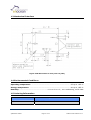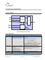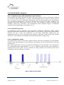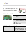
1
Transmitter Module
PTM 230
User Manual V1.1
February 2006
Revision History
The following major modifications and improvements have been made to the first version of
this document (User Manual PTM 230, V1.0):
No
Major Changes
0.91
0.92
0.93
0.95
0.96
Requirements for energy converter added in 2.1
Section 3.1 Antenna Mounting added
Drawing for contact pads added
Specification for energy generator modified, tolerance in PCB dimensions modified
Minimal switching interval defined in 1.2 and 1.1; change in 2.3.2 maximum 3 subtelegrams are transmitted; hole diameter changed to 2mm in 1.3; antenna end
should be insulated in 3.1
Mechanical drawing updated; additional pads for rocker information described;
telegram content specified; minimal switching time changed to 50ms.
Humidity range reduced to 93% max.
Minor changes
Editorial changes
Energy pulse shape modified
1.0
1.01
1.02
1.03
1.1
Published by EnOcean GmbH, Kolpingring 18a, 82041 Oberhaching, Germany
www.enocean.com, [email protected], phone ++49 (89) 6734 6890
© EnOcean GmbH
All Rights Reserved
Important!
This information describes the type of component and shall not be considered as assured characteristics. No
responsibility is assumed for possible omissions or inaccuracies. Circuitry and specifications are subject to change
without notice. For the latest product specifications, refer to the EnOcean website: http://www.enocean.com.
As far as patents or other rights of third parties are concerned, liability is only assumed for modules, not for the
described applications, processes and circuits.
EnOcean does not assume responsibility for use of modules described and limits its liability to the replacement of
modules determined to be defective due to workmanship. Devices or systems containing RF components must meet
the essential requirements of the local legal authorities.
The modules must not be used in any relation with equipment that supports, directly or indirectly, human health or life
or with applications that can result in danger for people, animals or real value.
Components of the modules are considered and should be disposed of as hazardous waste. Local government
regulations are to be observed.
Packing: Please use the recycling operators known to you. By agreement we will take packing material back if it is
sorted. You must bear the costs of transport. For packing material that is returned to us unsorted or that we are not
obliged to accept, we shall have to invoice you for any costs incurred.
©EnOcean GmbH
Page 2 of 12
PTM 230 User Manual V1.1
Table of Contents
Revision History _________________________________________________________________________ 2
Table of Contents________________________________________________________________________ 3
1. GENERAL DESCRIPTION________________________________________________________________ 4
1.1 Functional Principle _________________________________________________________________ 4
1.2 Features Overview __________________________________________________________________ 4
1.3 Mechanical Interface________________________________________________________________ 5
1.4 Environmental Conditions __________________________________________________________ 5
1.5 Ordering Information _______________________________________________________________ 5
2. FUNCTIONAL DESCRIPTION ___________________________________________________________ 6
2.1 Block Diagram _______________________________________________________________________ 6
2.2 Pin Description ______________________________________________________________________ 6
2.3 PTM 230 Radio Telegram ___________________________________________________________ 7
3. APPLICATIONS INFORMATION ________________________________________________________ 9
3.1 Antenna Mounting___________________________________________________________________ 9
3.2 Transmission Range _______________________________________________________________ 10
3.3 Approval Requirements ____________________________________________________________ 10
4. DEVELOPMENT TOOLS _________________________________________________________________ 11
4.1 Evaluation Kit EVA 100 ____________________________________________________________ 11
4.2 On-board Overview EVA-PCB ______________________________________________________ 11
4.3 EVA 100 Scope of Supply and Ordering Information _____________________________ 11
5. DECLARATION OF CONFORMITY ______________________________________________________ 12
©EnOcean GmbH
Page 3 of 12
PTM 230 User Manual V1.1
1. GENERAL DESCRIPTION
The radio transmitter module PTM 230 from EnOcean
enables the implementation of batteryless radio switches
for applications in e.g. building technology or industrial
automation. Power is provided by an external electrodynamic power generator such as ECO 100 or a short
energy pulse.
The PTM 230 module serves the 868 MHz air interface protocol
of EnOcean. Together with the receiver module RCM 120, this
module can be easily integrated in operation and control units for the implementation of
different application-specific system solutions.
1.1 Functional Principle
When a short energy pulse is supplied to the PTM 230 module an RF telegram is transmitted
including a 32-bit module ID and the polarity of the supply voltage. In addition the information
of 2 inputs is transmitted. With the 2 inputs one rocker of a PTM 200 can be simulated.
1.2 Features Overview
Power supply: ........................... external electro-dynamic power generator or energy pulse
Frequency:...................................................................................................868.3 MHz
Transmission power:.................................................................................max. 10 mW
Modulation type: ...................................................................................................ASK
Data rate: ......................................................................................................120 kbps
Channel bandwidth: ........................................................................................ 280 kHz
Minimal switching interval: ............................................................................... 45 ms
Antenna:.............................................. λ/4-whip antenna mountable, no antenna mounted
Transmission range: .................... approx. 300 m free field, 10m in industrial environment
(range strongly dependent on surrounding material and position relative to energy harvester or other metal surfaces)
Serial Telegram type (RCM120): .............................................................RPS of type 2
Module identifier: ............................................ individual 32-bit ID (factory programmed)
Radio standards: ......................................... R&TTE 1999/5/EC, ETSI EN 300220-3 V1.1.1
EMC standards: .............................. 89/336/EC, 92/31/EWG, EN 61000-6-2, EN 61000-6-4
.....................................................................EN 301489-01 V1.5.1 , EN301489-03 V1.4.1
©EnOcean GmbH
Page 4 of 12
PTM 230 User Manual V1.1
1.3 Mechanical Interface
PWR2
PWR1
Figure: PCB Dimensions in mm (view on pads)
1.4 Environmental Conditions
Operating temperature: ..................................................................... -25 up to +65 °C
Storage temperature: ........................................................................ -40 up to +85 °C
Humidity:................................................... 0 % to 93 % r.h., non-condensing, no IP-class
1.5 Ordering Information
Type
EnOcean Ordering Code
PTM 230
S3011-A230
©EnOcean GmbH
Page 5 of 12
PTM 230 User Manual V1.1
2. FUNCTIONAL DESCRIPTION
2.1 Block Diagram
Data
SW1
Processor
Vcc
HF
SW2
ANT
Polarity
DC Power
PWR 1
PWR 2
Power
Converter
Figure: Block diagram of PTM 230
2.2 Pin Description
Symbol
PWR1, PWR2
Function
Inputs for EnOcean energy
Operational characteristics
Maximum wire length to energy converter:
5cm each
converter ECO 50 or ECO 100
or equivalent energy pulse
Requirements for energy pulse:
•
EPulse > 0.45mWs
•
2.5V ≤ Umax,Pulse ≤ 5.5V
• 0,001ms ≤ TPulse ≤ 11ms
(voltage measured with module connected;
required pulse width depends on voltage,
pulse shape and source impedance)
SW1, SW2
Vcc
ANT
©EnOcean GmbH
Digital inputs for simulation of
O-button and I-button signal of
a PTM 200
Connect SW1 to Vcc for
simulation of “I-button”
Connect SW2 to Vcc for
simulation of “O-button”
Supply for SW1 and SW2
Pad for antenna mounting
Maximum wire length to Vcc: 3cm each
The signal at SW1 and SW2 must be available >
100µs before and > 10ms after energy is
supplied to the module.
Maximum wire length to SW1, SW2: 3cm
87mm whip antenna as defined in 3.1 Antenna
Mounting
Page 6 of 12
PTM 230 User Manual V1.1
2.3 PTM 230 Radio Telegram
2.3.1 Frequency range and transmission cycle allowed
The EnOcean technology operates the 868.3 MHz radio channel, which is exclusively released
for short-time data transmission in Europe. All transmitters have to stick to a duty cycle of
max. 1% within one hour. Permanent transmitters such as radio earphones are not allowed.
For conventional applications, it must be ensured that the PTM 230 radio module is not
operated more than 15000 times within one hour (one operation: button is pressed and
released). Within this calculation, the extraordinary short telegram length is considered
including three subtelegrams (see Chapter 2.2.3).
2.3.2 Modulation process
As modulation process, EnOcean uses incoherent amplitude modulation (ASK). Digital
amplitude modulation enables the implementation of very efficient energy-saving transmitters
because only the “1”-bits are transferred. At the same interference signal level, the
transmission security of the alternative FSK method is identical to that of the ASK method
(Reference: Pehl, Digitale und analoge Nachrichtenübertragung, Hüthig 2001).
2.3.3 Transmission timing
The transmission timing of the radio module PTM 230 has been developed to avoid possible
collisions with data packages of other EnOcean transmitters as well as disturbances from the
environment.
With each transmission cycle, three identical subtelegrams are transmitted. The transmission
of a subtelegram lasts approximately 0.7 ms. To optimize data security, each telegram is
repeated twice within about 20 ms, whereas the delay between the second and the third
transmission burst is effected at random.
Figure: PTM 230 radio timing
©EnOcean GmbH
Page 7 of 12
PTM 230 User Manual V1.1
2.3.4 Telegram Data
The PTM 230 transmits an EnOcean radio telegram which is provided at the serial output of a
RCM 120 or TCM 120 module with the following parameters:
Unique factory programmed 32bit ID
Data2, Data1, Data0=0
Data3 and Status as follows:
SW1
open
Vcc
open
Vcc
SW2
open
open
Vcc
Vcc
ORG
0x05
0x05
0x05
0x05
Data3
000PXXXX
000P0000
001P0000
001P0001
Status
XX10RRRR
XX11RRRR
XX11RRRR
XX11RRRR
P=polarity, X=reserved, R=repeater counter
The polarity P is defined as follows:
PWR1
+
-
©EnOcean GmbH
PWR2
+
P
1
0
Page 8 of 12
PTM 230 User Manual V1.1
3. APPLICATIONS INFORMATION
3.1 Antenna Mounting
Positioning and choice of receiver and transmitter antennas are the most important factors in
determining system transmission range. The PTM 230 modules are supplied without antenna.
For standard applications the use of a whip antenna is recommended (87 mm/ 0.14 mm2 Cuwire). This antenna enables very compact unit with good radio characteristics. For mounting
the antenna, the following notes should be considered to optimize the system performance:
Mounting a 1/4-wave whip antenna:
For good transmit performance, great care must be taken about the space immediately around
the antenna since this has a strong influence on screening and detuning the antenna. The
antenna should be drawn out as far as possible and must never be cut off. Primarily, the far
end of the wire should be mounted as far away as possible from all metal parts, PCB strip lines
and fast logic components (e.g. microprocessors). To avoid radio frequency hash from the
motherboard, which desensitizes the unit, PCB strip lines on the motherboard should be
designed as short as possible, and using PCB ground plane layer is also recommended. To
avoid possible damage to the module the end of the antenna should be insulated.
Note that 868 MHz whip antennas do not show any directional effects under free-field radiowave propagation conditions (spot-wise radiator).
(tinned)
bared, twisted and tinned
Cu-wire, 0.14 mm2 cross section
according to VDE 0812 or
0245 Cl.5 or Cl. 6
TI2, according
Insulation:PVC
Isolation:
PVCmixture
mixtureTI2,
to VDE 0207-4
Figure: Specification of whip antenna
©EnOcean GmbH
Page 9 of 12
PTM 230 User Manual V1.1
3.2 Transmission Range
The main factors that influence the system transmission range are type and location of the
antennas of the receiver and the transmitter, type of terrain and degree of obstruction of the
link path, sources of interference affecting the receiver, and “dead” spots caused by signal
reflections from nearby conductive objects. Since the expected transmission range strongly
depends on these system conditions, range tests should categorically be performed before
notification of a particular range that will be attainable by a particular application.
The following figures for expected transmission range are considered by using the PTM 100
radio transmitter module and the RCM 110 or RCM 120 radio receiver module with the
preinstalled whip antennas and may be used as a rough guide only:
•
10 m in industrial applications with metal in the vicinity
•
30 m for obstructed environment (e.g., through two brick walls inside a building)
•
300 m for unobstructed environment (“free field”)
Further notes to determine the transmission range within buildings are available as download
from www.enocean.com.
3.3 Approval Requirements
The modules bear the EC conformity marking CE and conform to the R&TTE EU-directive on
radio equipment. The assembly conforms to the European and national requirements of
electromagnetic compatibility. The conformity has been proven and the corresponding
documentation has been deposited at EnOcean. The modules can be operated without
notification and free of charge in the area of the European Union, in Switzerland, in Cyprus, in
Czech, in Estonia, in Hungary, in Latvia, in Lithuania, in Malta, in Poland, in Romania and in
Slovenia. The following provisos apply:
•
EnOcean RF modules must not be modified or used outside their specification
limits.
•
EnOcean RF modules may only be used to transfer digital or digitized data.
Analog speech and/or music are not permitted.
•
The final product incorporating EnOcean RF modules must itself meet the
essential requirement of the R&TTE Directive and a CE marking must be affixed
on the final product and on the sales packaging each. Operating instructions
containing a Declaration of Conformity has to be attached.
•
If transmitters are used according to the regulations of the 868.3 MHz band, a
so-called “Duty Cycle” of 1% per hour for each transmitter must not be exceeded
(also see Chapter 2.3.1).
©EnOcean GmbH
Page 10 of 12
PTM 230 User Manual V1.1
4. DEVELOPMENT TOOLS
4.1 Evaluation Kit EVA 100
EVA 100 is an evaluation kit to support a simple setting-up
operation of the receiver side when the EnOcean transmitter
module PTM 230 is evaluated. EVA 100 supports a quick
evaluation of all RCM 110 and RCM 120 receiver operation
modes and supports the fast development of applications.
4.2 On-board Overview EVA-PCB
Symbol
Adaptor
RCM 100
Test
Connector
Vcc
GND
GND
R0
R1
R2
R3
GND
EVG
GND
PWM
RS232
Function
Female jack for power supply
Female header for plug-in RCM 110 or RCM
120 module
Female header connected directly to RCM
leads
Jack to disconnect RCM power supply
Ground connector for control outputs
Functional control outputs. Also indicate
current learning mode status.
R0..3 are directly connected to the OUT_0..3
output pins of RCM 110/120 module
Analog output to drive an Electronic Control
Gear
50 kHz PWM output
DB9 female connector
4.3 EVA 100 Scope of Supply and Ordering Information
Type
EVA 100
©EnOcean GmbH
EnOcean Ordering Code
H3004-G100
Scope of supply
• Evaluation Board EVA-PCB
• EnOcean radio modules PTM 100 (incl.
Rocker Model), STM 100, RCM 110 and
RCM 120
• CD with PC-link Monitor Software and
detailed kit documentation
• Wall power supply for EVA-PCB
• Convenient equipment case
Page 11 of 12
PTM 230 User Manual V1.1
5. DECLARATION OF CONFORMITY
Will be available with PTM 230 series release
©EnOcean GmbH
Page 12 of 12
PTM 230 User Manual V1.1