1
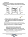
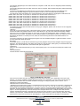
4. Data Output Input. Output from RS232. Each telegram received flawlessly is generally output on the COM port side without any further processing. The meaning of the data bytes DATA_BYTE0...3 is depending on the respective device type. Thus, it is described in the corresponding product data sheets. In Filtering mode the only tied ID could reached the RS232 output. Input to RS232. You could send two type of command Gateway configuration command and Transmit command. Detail command description you could find in APENDIX. 5. Installation 1. Connect interface to any desired serial COM port, serial cable max length 20m using shielded twisted pair cable. 2. Connect 5 VDC power supply to mini jack attached to serial connector or connect your cable to P3 on the gateway’s PCB. 3. Use TCM monitor software for receiving or transmitting EnOcean telegrams or refer to last version of EnOcean communication profile for using other devices supporting free programmed RS232 interfaces. You can use free WinEtel Communication Software ( please download it from http://www.enocean.com/en/download/ ) EnOcean WinEtel receives, sends and analyses EnOcean RF telegrams. Telegrams are displayed and can be logged with time stamp. In combination with tranceivers its possible to simulate e.g. sensors or switch modules (e.g. PTM 200). WinEtel allows to send and retrieve dedicated configuration commands (TCT/RCT). Further it is possible to extend the basic terminal functionality for specific use and application cases with Plug Ins. 4. 6. Transmission range The main factors that influence the system transmission range are type and location of the antennas of the receiver and the transmitter, type of terrain and degree of obstruction of the link path, sources of interference affecting the receiver, and “dead” spots caused by signal reflections from nearby conductive objects. Since the expected transmission range strongly depends on this system conditions, range tests should categorically be performed before notification of a particular range that will be attainable by a certain application. The following figures for expected transmission range are considered by using a PTM, a STM or a TCM radio transmitter device and the TCM radio receiver device with preinstalled whip antenna and may be used as a rough guide only: Line-of-sight connections: Typically 30 m range in corridors, up to 100 m in halls Plasterboard walls / dry wood: Typically 30 m range, through max. 5 walls Line-of-sight connections: Typically 30 m range in corridors, up to 100 m in halls Ferro concrete walls / ceilings: Typically 10 m range, through max. 1 ceiling Fire-safety walls, elevator shafts, staircases and supply areas should be considered as screening. The angle at which the transmitted signal hits the wall is very important. The effective wall thickness – and with it the signal attenuation – varies according to this angle. Signals should be transmitted as directly as possible through the wall. Wall niches should be avoided. Other factors restricting transmission range: Switch mounted on metal surfaces (up to 30% loss of transmission range) Hollow lightweight walls filled with insulating wool on metal foil False ceilings with panels of metal or carbon fibre Lead glass or glass with metal coating, steel furniture www.exesense.com Представитель в России – ATLAS Group, Москва, Дмитровское шоссе 100 стр. 2 phone +7 (495) 64-335-65 e-mail: [email protected], [email protected] www.atlasgroup.ru