1
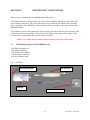
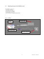
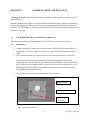
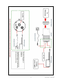
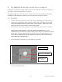
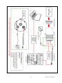
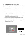
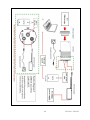
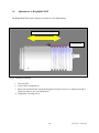
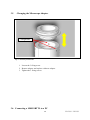
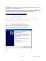
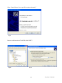
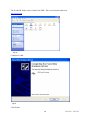
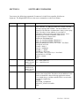
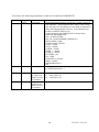
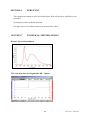
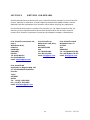
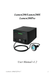
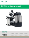
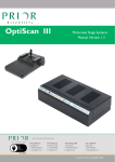
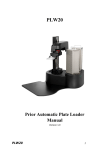
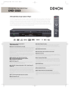
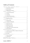
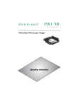
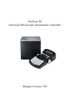
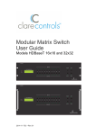
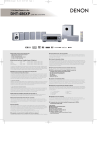
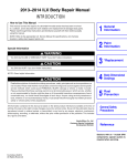
Brightfield LED LDB100/LDB101 Manual Version 1.01 Table of Contents SECTION 1 IMPORTANT SAFETY INFORMATION 2 1.1 IMPORTANT SAFETY INFORMATION 2 SECTION 2 4 2.1 2.3 Identifying the parts of the LDB100 System Identifying the parts of the LDB101 System SECTION 3 3.1 3.2 3.3 3.4 3.5 3.6 IDENTIFYING YOUR SYSTEM WORKING YOUR SYSTEM The Brightfield LED as a Stand-alone lightsource 3.1.1 Installation Identifying the parts of the LDB101 System 3.2.1 Installation The Brightfield LED with a Prior LDBUSBTTL converter 3.3.1 Installation Adjustments to the Brightfield LED Changing the Microscope Adapter Connecting a LDBUSBTTL to a PC 3.6.1 Installing the LDBUSBTTL in Windows 7 3.6.2 Installing the LDBUSBTTL in Windows XP 4 5 6 6 6 8 8 10 10 12 13 14 14 14 SECTION 4 SOFTWARE COMMANDS 17 SECTION 5 REPLACEMENT & SPARE PARTS 19 SECTION 6 SERVICING 20 SECTION 7 TECHNICAL SPECIFICATIONS 20 SECTION 8 RETURNS AND REPAIRS 21 1 LDB100 / LDB101 SECTION 1 IMPORTANT SAFETY INFORMATION SAFETY WARNINGS Always observe the following safety precautions Before using the illumination system, please follow and adhere to all warnings, safety and operating instructions located on the product and in this User Manual. Use only as specified by these operating instructions or the intrinsic protection provided by the unit may be impaired. It is safe for use in an ambient temperature from 5 to 40°C with relative humidity to 80% up to 31°C decreasing linearly to 50%rH at 40°C. Do not expose the product to water or moisture while energised. Do not allow moisture to penetrate openings in the case. If this occurs allow the unit to dry out unpowered before switching on again Do not expose the product to extreme hot or cold temperatures. Do not expose the product to open flames. Do not allow objects to fall on or liquids to spill on the product. Do not replace detachable mains supply cords by inadequately rated cords. Do not cover or impede ventilation to this system. Do not stare into the light output of the LED units. Connect the AC power cord only to designated power sources as marked on the product. Make sure the electrical cord is located so that it will not be subject to damage. Make sure the system in installed so that the reaer panel power switch is easily accessible. For use in a manner not specified in this manual contact Prior before any work is done. To reduce the risk of damage, unplug the product from the power source before connecting the components together. DANGER - never alter the AC cord or plug. If the plug will not fit into the outlet, have a proper outlet installed by a qualified electrician. Only suitably rated and approved mains cord-sets should be used as per the country of use. Use only the proper type of power supply cord set (provided with the system) for this unit. Do not attempt to disassemble the product. Doing so will void the warranty. This product does not contain consumer serviceable components. Service should be performed by Authorised Service Centres. 2 LDB100 / LDB101 Only the exterior of this product should be cleaned using a damp lint- free cloth. This warning symbol indicates that the surface may be hot. Save this manual as it contains important safety information and operating Instructions 3 LDB100 / LDB101 SECTION 2 IDENTIFYING YOUR SYSTEM There are two variants to the Prior Brightfield LED system. The LDB100 system is powered directly from a Prior controller (OptiScan or ProScan) with active shutter connectors. The power and control are provided by the shutter cable from the Prior controller to the LED Body. You must have a Prior controller to use this version of the Brightfield LED. The LDB101 comes with a stand alone power supply; this allows the unit to be operated with out the need of a Prior controller. The unit is powered directly from the mains supply. This version can be used without the need for a Prior controller. NOTE – It is important to connect all parts before powering on the units. 2.1 Identifying the parts of the LDB100 System The LDB100 consists of: 1 off, Main LED body 1 off, Microscope Adapter. 1 off Intensity Control Pot 1 off Prior Shutter cable Fig 1 – LDB100 Microscope Adapter Shutter Cable LED Body Intensity Control Pot 4 LDB100 / LDB101 2.2 Identifying the parts of the LDB101 System The LDB101 consists of: 1 off, Main LED body 1 off, Microscope Adapter. 1 off Intensity Control Pot 1 off 24Volt Power supply & mains cable. Fig 2 – LDB101 LED Body 24V Power Supply Microscope Adapter Intensity Control Pot 5 LDB100 / LDB101 SECTION 3 WORKING WITH YOUR SYSTEM The Brightfield LED can be controlled either manually or under software control, (using 3 rd party software). Both the LDB100 and LDB101 are supplied with a manual intensity control pot. Intensity is regulated by turning the dial clockwise to increase intensity and anticlockwise to decrease intensity. The LED light can also be turned on and off via and integrated toggle switch on the intensity control pot. 3.1 The Brightfield LED as a Stand-alone Lightsource. This option only allows for manual control of the LED via the Intensity control pot. 3.1.1 Installation Connect Intensity Control Pot to the socket on the LED Head. (See system Diag. 1) Connect the 24V power supply to the socket on the LED Head, and plug in mains cable. Turn on mains switch to give power to the LED Head, and Intensity Control Pot. On/Off button on the Intensity Control Pot Assembly maintains the on or off condition before and after the cycling of mains power. The Power Indicator LED (see fig 3) will be lit if the toggle switch is in the ON position. If the mains power is on and the Power Indicator LED is not illuminated, please press the ON/OFF toggle switch make the control pot active. Use the Intensity Control Pot to set the light levels required. Power Indicator Intensity Control Wheel ON/OFF Toggle Switch Fig 3 – Intensity Control Pot 6 LDB100 / LDB101 7 LDB100 / LDB101 3.2 The Brightfield LED with a Prior controlle r (Proscan or Optiscan). Using this set up allows for either manual control of the LED via the intensity control pot or via software control through the Prior controller. Through software control the LED can be turned on and off via the standard Prior shutter commands. LED illumination intensity can not be adjusted via software control. 3.2.1 Installation Connect Intensity Control Pot to the socket on the LED Head. (See system Diag. 2) Connect one end the Prior shutter cable the socket on the LED Head, and the other end to and available Shutter port on the back of the controller. Make a note of the shutter port for use in any software control of the system. Turn on Prior controller to give power to the LED Head, and Intensity Control Pot. On/Off button on the Intensity Control Pot Assembly maintains the on or off condition before and after the cycling of mains power. The Power Indicator LED (see fig 4) will be lit if the toggle switch is in the ON position. If the mains power is on and the Power Indicator LED is not illuminated, please press the ON/OFF toggle switch make the control pot active. Use the Intensity Control Pot to set the light levels required. Power Indicator Intensity Control Wheel ON/OFF Toggle Switch Fig 4 – Intensity Control Pot 8 LDB100 / LDB101 9 LDB100 / LDB101 3.3 The Brightfield LED with a Prior LDBUSBTTL converter. Using this set up allows for either manual control of the LED via the intensity control pot or via software control through the LDBUSBTTL converter. The LDBUSBTTL emulates a Prior Proscan controller with 1 shutter port. Through software control the LED can be turned on and off via the standard Prior shutter commands. LED illumination intensity can not be adjusted via software control. 3.3.1 Installation Connect Intensity Control Pot to the socket on the LED Head. (See system Diag. 3) Connect a BNC-BNC cable to the TTL port on the LED Head, and the other end to the TTL socket on the LDBUSBTTL. Connect the USB (Type B) cable to the LDBUSBTTL and the other to a free USB slot on your PC. The LDBUSBTTL may need to have drivers installed for it to be recognised b y the PC. (See section 3.6 Connecting a LDBUSBTLL to a PC) Turn on mains switch to give power to the LED Head, and Intensity Control Pot. On/Off button on the Intensity Control Pot Assembly maintains the on or off condition before and after the cycling of mains power. The Power Indicator LED (see fig 5) will be lit if the toggle switch is in the ON position. If the mains power is on and the Power Indicator LED is not illuminated, please press the ON/OFF toggle switch make the control pot active. Use the Intensity Control Pot to set the light levels required. Power Indicator Intensity Control Wheel ON/OFF Toggle Switch Fig 5 – Intensity Control Pot 10 LDB100 / LDB101 11 LDB100 / LDB101 3.4 Adjustments to Brightfield LED The Brightfield LED can be adjusted to obtain an even illumination. Direction of Adjustment Locking Screw Fig 6 – Intensity Control Pot 1. Turn on LED 2. Loosen the Locking Screw 3. Move the lead head back and forth along the direction of travel, as indicated in Fig 6. Until you achieve an even illumination. 4. Tighten the Locking Screw. 12 LDB100 / LDB101 3.5 Changing the Microscope Adapter Fixing Screws Fig 7 – Intensity Control Pot 1. Loosen the 3 fixing screw 2. Remove adapter and replace with new adapter. 3. Tighten the 3 fixing screws. 3.6 Connecting a LDBUSBTTL to a PC 13 LDB100 / LDB101 The LDBUSBTTL will emulate a Prior Proscan controller with one shutter connected, and can be set up in 3rd party software this way. LDBUSBTTL may require a driver to be installed, if so, then please go the following section on the Prior Scientific website and download PL200/ES10ZE USB Drivers; http://www.prior.com/downloadcentre/dc_software.html 3.6.1 Installing the LDBUSBTTL in Windows 7 Plug in the USB cable to the LDBUSBTTL and the computer, Windows 7 should automatically recognize the device and install the appropriate drivers. 3.6.2 Installing the LDBUSBTTL in Windows XP Plug in the USB cable to the LDBUSBTTL and the computer; When prompted select No, not at this time, then click NEXT. Fig 8 14 LDB100 / LDB101 Select “Install from a list or specific location (advanced)” Fig 9 Browse to the location of Eval232R, click NEXT. Fig 10 Fig 11 15 LDB100 / LDB101 The Eval232R folder can be found in the SDK. This can be downloaded from www.prior.com. Fig 12 Contents of SDK. Fig 13 Click Finish. 16 LDB100 / LDB101 SECTION 4 SOFTWARE COMMANDS You can use the following commands if connected via the Prior controller (ProScan or Optiscan). The Brightfield LED uses the same command set as the Prior Shutter. Command Argument Response Description ? None Text String 8 s,c 8 s Shutter s R If LED is not fitted E,20 will be returned c If LED is not fitted E,20 will be returned 0,1 Reports information about the peripherals currently connected to the controller. e.g. DRIVE CHIPS 10011 means Z and 4th axis chips missing, SHUTTERS = 110 means shutter 1 not connected. The final line of information is always a line saying END. This allows for the addition of extra fields of information without effecting application software. Users should always read lines in until the END is seen. A typical response is shown below: PROSCAN INFORMATION DSP_1 IS 4-AXIS STEPPER VERSION 2.7 DSP_2 IS 2-AXIS STEPPER VERSION 2.7 DRIVE CHIPS 010111 (F2 F1 A Z Y X) 0 = Not Fitted JOYSTICK ACTIVE STAGE = H101/2 FOCUS = NORMAL FILTER_1 = NONE FILTER_2 = HF110-10 SHUTTERS = 001 (S3 S2 S1) 0 = Not Fitted AUTOFOCUS = FITTED VIDEO = NONE END Turns on or off the LED s (value ‘1’, ‘2’ or ‘3’, If c = 0 the LED is on If c = 1 the LED is off. Returned the status c of the LED s Prints information about LED ‘s’. The information end is always a line saying END. This allows for the addition of extra fields of information without effecting application software. Users should always read lines until the END is seen in order to maintain compatibility. Example SHUTTER_1=NORMAL DEFAULT_STATE=CLOSED END 17 LDB100 / LDB101 You can use the following commands if connected via the Prior LDBUSBTTL. Command Argument Response Description ? None Text String VER None Text String Reports information about the peripherals currently connected to the controller. The information end is always a line saying END This allows for the addition of extra fields of information without effecting application software. Users should always read lines in until the END is seen. A typical response from LDBUSBTTL is shown below PROSCAN INFORMATION DSP_1 IS NOT FITTED DSP_2 IS 3 AXIS STEPPER VERSION 0.0 DRIVE CHIPS 111000 JOYSTICK NOT FITTED STAGE = NONE FOCUS = NONE FOURTH = NONE FILTER_1 = NONE FILTER_2 = NONE SHUTTERS = 001 LED = 0000 AUTOFOCUS = NONE VIDEO = NONE HARDWARE REV A END Returns the version of the code fitted to the unit. Eg. USBTTLinterfaceV1.3 8 s,c 8 s R If LED is not fitted E,20 will be returned c If LED is not fitted E,20 will be returned Turns on or off the LED s (value ‘1’) If c = 0 the LED is on If c = 1 the LED is off. Returned the status c of the LED s 18 LDB100 / LDB101 SECTION 5 REPLACEMENT & SPARE PARTS W2288 Shutter Cable W4114 24Volt Power Supply LM317 Intensity Control Pot Microscope Adapters LM685 Olympus Microscope Adapter. LM686 Leica Microscope Adapter. LM687 Zeiss Microscope Adapter. The Prior LDB100/101 will fit Nikon Ti, 80i, 90i microscopes without the need for an additional adapter. 19 LDB100 / LDB101 SECTION 6 SERVICING This equipment contains no user-serviceable parts. Refer all repairs to qualified service personnel. Opening the product voids the warranty. For approved service outlets contact your nearest Prior office.. SECTION 7 TECHNICAL SPECIFICATIONS Relative Spectral Distribution TTL Switching time for Brightfield LED – 100usec 20 LDB100 / LDB101 SECTION 8 RETURNS AND REPAIRS Should you experience problems with your LumenLED System and want to send it back for service, warranty or otherwise, a Return Material Authorisation (RMA) number must be obtained from the appropriate Prior Scientific office before returning any equipment. For North and South America contact Prior Scientific Inc., for Japan contact Prior KK, for Germany, Austria and Switzerland contact Prior GmbH and for the all other countries contact Prior Scientific Instruments Limited on the telephone numbers shown below. Prior Scientific Instruments Ltd, Unit 4, Wilbraham Road, Fulbourn, Cambridge, ENGLAND, CB1 5ET Tel: 01223 881711 Fax: 01223 881710 email: [email protected] Prior Scientific Inc. 80 Reservoir Park Drive, Rockland, MA 02370-1062 USA Tel: 781 878 8442 Fax: 781 878 8736 email: [email protected] Prior Scientific GmbH Wildenbruchstr. 15 D-07745 Jena GERMANY Tel: +49 (0)3641 675 650 Fax: +44 (0)3641 675 651 email: [email protected] Prior Scientific KK Kayabacho 3rd Nagaoka Bldg. 10F 2-7-10, Nihonbashi Kayabacho Chuo-Ku Tokyo 103-0025 JAPAN Tel: +81 (0) 3 5652 8831 Fax: +81 (0) 3 5652 8832 email: [email protected] 21 LDB100 / LDB101