1
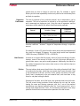
Fadal
Maintenance Manual
Section 14: General Information
Helpful Formulas
Temperature
Conversion Factors
Electrical References
Expansion
Coefficients
March 2003
Degrees Fahrenheit (F) = (9/5 x degrees C) + 32
Degrees Celsius (C) = 5/9 x (degrees F-32)
Inch (in) = millimeter x 0.03937
Inch (in) = centimeter x 0.3937
Millimeter (mm) = inch x 25.4
Centimeter (cm) = inch x 2.54
Liter = gallon (U.S.) x 3.7854
Gallon (U.S.) = liter x 0.2642
Bar = Pounds per Square Inch (psi) x 0.0689
Pounds per Square Inch (psi) = Bar x 14.5
Newton-metre (N/m) = pound/foot x 14.5939
Pound/foot = Newton-metre (N/m) x 0.0685
Newton-metre (N/m) = ounce-inch x 0.00706
Ounce-inch = newton-metre (N/m) x 0.1416
Formulas from Ohm’s Law
Amperes (I) = Volts (E) / Resistance (R)
Resistance (R) = Volts (E) / Amperes (I)
Volts (E) = Amperes (I) x Resistance (R)
Single-Phase
Kilovolt-Amperes (KVA) = (Volts x Amperes) / 1000
Three-Phase
Kilovolt-Amperes (KVA) = (Volts x Amperes x 1.73) / 1000
Formula
Expansion amount =
Coefficient x distance x degree of temperature change (Fahrenheit)
Coefficients
Steel
= .00000633
Cast Iron = .00000655
Aluminum = .00001244
Section 14: General Information
473
Fadal
Maintenance Manual
Fadal Machining
Centers Serial
Numbers
The new serial number scheme is as follows:
Product
ID
01 – VMC
02 – Rotary
03 – Re-Man
99
9999
Year of
Manufacture
99
Machine
Number
9999
Month of
Manufacture
Example: 042000110020
[04 2000 11 0020]
For reference the old serial number scheme:
Year of
Manufacture
99 99 999
Month of
Manufacture
474
Machine
Number
Example: 9911020
[99 11 020]
Section 14: General Information
March 2003
Fadal
Maintenance Manual
For communication problems several factors must be examined. Review the
environment, then check the file, the VMC, the cables, the computer, and finally
the computer's communications software. Any one of these systems can
propagate a communication problem.
Communications
Troubleshooting
Environment
In areas where lightning strikes are common, communications can be
interrupted when or
after lightning has struck a power line. The lightning may affect the memory of
the CNC control, which would then have to be zeroed from the DI mode. It is
suggested to call a service person or see the maintenance manual for this
zeroing procedure.
• An RS-232 surge suppressor adds protection in this kind of environment.
File
1) Has the file ever successfully been transmitted to the VMC before? If the file
has been transmitted before, has it recently been edited and has
something been introduced into the file? Use an editor or word processor
which will show hidden characters. If hidden characters are present in the
file, remove them.
2) If the file has not been successfully transmitted, use an editor or word
processor which will show hidden characters. If hidden characters are
present in the file, remove them.
a. The only accepted characters allowed before the initial percent sign are
DNC, DNCX, or TA,1. In addition, no O words are allowed in DNC mode.
Example:
DNC
%
b. A two-second dwell is required between the DNC command and the first
percent symbol (%). If the software being used to transmit the program
cannot support this dwell time, remove the DNC, DNCX, or TA,1 command from the file and type the command at the VMC before starting
file transmission.
3) When a file is posted for a paper tape, or when a paper tape is read and
placed on a disk, it may have leader characters before the initial percent
sign — they need to be removed.
4) If some of the file can be transmitted, but some of it cannot, check for
syntax errors.
a) Examine the area in the file for syntax errors and repair them.
For example, double motion words or missing words are syntax errors.
March 2003
Section 14: General Information
475
Fadal
Maintenance Manual
Example:
X1.23 X4.5 —- Double motion words
-Y2.3 —- Incorrect placement of - (minus)
534 —- No word at all
.
•
Use the TA,1,1 command for program transmission so that the control
will halt transmission and display the line where the syntax error occurs.
5) If a word processor or editor is used to write the program, it must be saved
in a text only format. Some processors will add formatting characters to the
file which will disallow communications.
VMC
1) Check to see if the grounding wires are properly attached.
a. The only proper and acceptable primary ground is a single continuous
copper wire attached from the ground bus in the junction box of the
VMC to the main power box of the building. A green sticker in the junction box further expounds the grounding requirement. Any other methods of grounding, such as grounding to the conduit, or to a ground rod,
are not acceptable and will lead to communication problems. See the
Pre-Installation section for grounding procedures.
b. Check to see if the screws attaching the ground wire to the VMC are
tight at both ends.
c. The ground wire of the RS-232 DB25 plug on the inside of the CNC control cabinet must be attached from the RS-232 port to the inside of the
CNC control cabinet. This wire is attached to pin #1 of the DB25 plug,
and is used to shield the cable at the VMC end ONLY (see the FADAL
VMC Users Manual for proper pin configuration).
•
If the paint has not been removed from this area, scrape the paint away
and re-attach the wire.
2) Check the cable from the RS-232 port on the inside of the CNC control
cabinet to the1030 board.
a. Sometimes this cable will work itself out of the plug. Press the plug into
the board to confirm a good connection.
b. Examine the cable for cuts or kinks and replace it if there is evidence of
damage.
3) For VMCs with a phone modem, make sure that the DB25 plug on the
inside of the CNC control cabinet is NOT plugged into the back of the
476
Section 14: General Information
March 2003
Fadal
Maintenance Manual
modem — if it is, it will interrupt normal communications through the RS232 port.
4) Use the mirror plug to test the 1030 board. The mirror plug is stored in the
bottom of the CNC control cabinet when the VMC is shipped. The plug is a
DB25 plug with no wires coming from it. On the inside of the plug, pins 2
and 3 are crossed to complete the communications path. Plug the mirror
plug into the RS-232 port on the outside of the back of the CNC control
cabinet.
a. Use the diagnostics mode to complete the test.
1) Move to the cold start position.
2) From the command mode type DI then press ENTER.
3) Type G0 3000 and press ENTER to enter the test menu.
4) Press 4 to select the RS-232 (1030) test.
5) Select a baud rate (generally the baud rate used in normal
communications).
6) Observe the screen.
•
Numbers next to the word TESTING should be changing constantly. If
this occurs, the1030 board has passed the test.
•
The numbers at the end of the other sentences should all be zero. If any
numbers appear at the end of these sentences it is an indication that
the 1030 board is faulty (assuming the cable was checked in step (2)
above). Note: The 1030 is rarely faulty.
•
If the diagnostics test passes, then it is safe to conclude that the VMC is
not at fault for a communication problem.
7) Press the manual button to end the communication test.
8) Power off the VMC, wait 10 seconds, then power on again.
5) Has the proper baud rate been selected at the VMC?
a. The CD,# command is used to select a baud rate. The MU command
has a list of each baud in the menu, or see the users manual for the
same list.
b. The SETP command, for the VMC parameters, can be used to select a
baud rate as default. The CD,# command will temporarily override the
selection in the SETP parameter page.
March 2003
Section 14: General Information
477
Fadal
Maintenance Manual
Cables
1) Verify that all connections between the communications cable and both the
VMC and the computer are firmly seated, including surge suppressors,
gender changers, and couplers. Pick up the cables and physically confirm
that each connection is properly together.
•
Loose cable connections are one of the most common causes of communication problems.
2) If a switch box is used, determine if the switch is in the proper position.
a. Examine the cable connections to see if they are in the correct ports.
b. Turn the switch handle back and forth a few times. Sometimes the contacts are corroded and turning the handle will temporarily correct the
problem.
•
If turning the handle corrects the problem, it is suggested to clean the
contacts or replace the switch box with a new one.
3) If the cable is coiled because the cable is too long, it is suggested to get a
shorter cable. The coiling may cause intermittent problems. The shorter the
cable the less chance a parity error will occur.
4) Check to see if the cable is draped over fluorescent lights or wrapped
around or connected on the high-voltage line for the power to the VMC or
other machines. This can cause RF noise and inductive voltages on the
cable, and communications will be interrupted from time to time.
a. Welding machines and EDM machines close to the VMC or the cable will
also cause communication problems. These machines also cause RF
noise which interrupts communications.
5) Open the DB25 plugs to see if the solder on the pins have been applied
properly. Cold solder joints for these wires will need to be soldered again.
6) Check to see if the wires are connected to the proper pins. See the
Communication section of the User Manual for the proper pinout. Confirm
that, with shielded cable, pin one is connected to the shield at the VMC side
only. Pin one cannot be connected at the computer side.
7) If straight cable is used then a null modem is required. A null modem cable
can be purchased from the FADAL Parts Department (part # 4537), or from
any computer store. A null modem is a short portion of cable or ribbon
cable that has pins 2 and 3 crossed. The crossover and the proper jumpers
on each end can be found in the Communication section of the User
Manual.
478
Section 14: General Information
March 2003
Fadal
Maintenance Manual
a. If a null modem is used that was supplied from FADAL, the switch must
be in the outward position away from the cable.
8) Use the mirror plug test as described in step 4 of the VMC section above to
test each section of cable from the VMC to the computer, replacing any
section that fails.
9) What is the length of the cable?
a. The longer the cable the slower the baud rate must be. The faster baud
rates may work for the longer cables, but the chance of losing information increases, the faster the baud. Try using a slower baud rate, and if
this works better, this may be the best solution. However this also may
indicate an IO port at the computer with low voltage. See the Computer
and Computer IO Port section below.
Computer and
Computer IO Port
1) Is the cable plugged into the proper port in the back of the computer?
a. Some ports are marked COM or SER — these are the proper ports.
b. If the ports are unmarked, a COM or serial port will be the male gender
port (the port with the exposed pins — the female gender port will have
sockets).
•
A gender changer plug may be needed if the gender on the cable will
not plug into the proper COM or serial port.
2) Is the port active?
a. Is the cable on the inside of the computer cover attached to the port?
b. Check the voltage across pins 2 and 7 while transmitting a file (use a
file large enough to allow time to check the voltage while the transmission is in progress). With the positive lead on pin 2 and the negative on
pin 7, the voltage should range between 10 and 12 volts. Any voltage
below 10 volts could result in interrupted communications.
•
A FLUKE meter (or equivalent) used to measure voltage must be set to
AC to obtain a reading.
3) When the computer was set up, did any interrupts interfere with the
communications port?
•
March 2003
A qualified computer setup person will be able to confirm that the port
is free of other interrupts.
Section 14: General Information
479
Fadal
Maintenance Manual
4) If an IBM-compatible computer has a serial mouse, is the mouse plugged
into the proper port?
a. Usually the serial mouse is used in COM1 or serial port one.
•
Move the mouse to COM1 and the VMC cable into COM2 and try to
communicate again.
•
If the mouse is not to be used during the DNC process, remove the
mouse software commands from the CONFIG.SYS and/or
AUTOEXEC.BAT file(s), and then reboot the computer. (CAUTION: Only
a person familiar with altering these files should perform this operation,
as these files are necessary for startup of an IBM-compatible computer.
Refer to the DOS manual for any questions regarding these files and
how to properly modify them.)
5) Some screen saver software can interrupt communication, change the baud
rate, or transmit an odd hidden character, when the screen saver starts to
display. Remove or disable the screen saver software and try to
communicate again.
6) The quality of the IO board must be considered. Multipurpose IO boards are
usually not recommended. High quality boards dedicated to only IO
functions are recommended. DigiBoard and Quad Tech are examples of
companies which produce high quality IO boards. These boards are
specific to the operating system used by the computer —one board is used
for DOS, another for Windows, and another for micro channel (IBM PS/2).
These boards usually test 12 volts across pins 2 and 7 at the computer, for
the best quality transmission.
• A FLUKE meter (or equivalent) used to measure voltage must be set to
AC to obtain a reading.
7) If a network board is installed in the computer, the computer technician who
installed the board must check for conflicting interrupts and IO addresses.
8) The FADAL Assist software has in its utility menu an RS-232 tester. Use the
mirror plug in the port and follow the instructions on the screen for test
number one.
Software
1) Check the communication parameters in the software.
a. TA, DNC, and PU (using Xon/Xoff)
• Baud rate - This is variable and it must match the baud rate set at the
VMC with the SETP command or with the CD,# command.
480
Section 14: General Information
March 2003
Fadal
Maintenance Manual
•
•
•
•
•
•
•
Parity - E (Even)
Data Bits - 7 (Seven)
Stop Bits - 1 (One)
EOB (End Of Block) - CR,LF (ASCII 13,10)
Starting and ending character - % (ASCII 37)
Xon/Xoff (Software handshaking) disabled for TA
enabled for DNC and PU
Hardware handshaking - disabled
b. DNCX (using XMODEM)
• Baud rate - This is variable and it must match the baud rate set at the
VMC with the SETP command or with the CD,# command.
• Parity - N (None)
• Data Bits - 8 (Eight)
• Stop Bits - 1 (One)
• EOB (End Of Block) - CR,LF (ASCII 13,10)
• Starting and ending character - % (ASCII 37)
• Packet Data Bytes - 128
• Hardware handshaking - disabled
For more information, see the file XMODEM.DOC on FADAL's Bulletin Board.
2) Use DOS to send a file, bypassing the communications software in the
computer. If this works, the software is in doubt.
a. From the DOS prompt type the following two DOS commands (shown in
bold):
MODE COM2:2400,E,7,1
MODE port:baud,parity,data bits,
stop bits
MODE = DOS command (followed by a space)
port = COM2
: = : (the : is required DOS syntax)
baud = 2400
, = , (the , is required DOS syntax)
parity = Even
, = , (the , is required DOS syntax)
data bits = 7
, = , (the , is required DOS syntax)
stop bits = 1
TYPE C:\CNCDATA\PN1234.NC>COM2
TYPE
March 2003
TYPE pathnamefilename>port
= DOS command (followed by a space)
Section 14: General Information
481
Fadal
Maintenance Manual
pathname = C:\CNCDATA\
filename = PN1234.NC
substitute the drive-and directories where
the file being sent to the VMC is stored.
substitute the name of the file sent to the VMC
> = > (the > is required DOS syntax to redirect file to COM2)
port = COM2
•
Note: Before typing these two lines, the VMC should be in the TA,1
mode ready to receive the program at 2400 baud.
•
Refer to the DOS manual for answers to additional questions about the
DOS commands used here.
3) Running DOS-based software from Windows may not work for communications.
Thermal Expansion
Overview
Thermal expansion is a natural occurrence in materials subject to heat, and
there are several sources of heat in any machining operation. In addition,
different materials react to heat at different rates, and different subsystems of
the VMC react to specific machining operations to different degrees, further
complicating matters. Finally, some machining practices designed to save time
may actually aggravate the expansion problem. Fortunately, there are a
number of ways in which the unwanted effects of thermal expansion can be
reduced to acceptable tolerances.
Recognizing Thermal
Expansion
Changes in positioning can have many causes, and correctly identifying the
cause is the key to solving the problem. Thermal expansion has a unique
'signature' which can aid in recognizing it as the culprit in a given situation.
Position changes that are due to thermal expansion occur gradually over time,
and continue to move in one general direction at a more or less constant rate.
The best way to combat thermal expansion is to accept the inherent nature of it
in a machining operation, and to take corrective measures, like those
suggested in this document, ahead of time.
Accuracy and
Repeatability
It should be noted that when accuracy and repeatability are quoted for a
machine, thermal expansion is not considered. These values are measured
and recorded only when the machine and all of its components are thermally
stable, usually by limiting test repetitions and time duration so that thermal
482
Section 14: General Information
March 2003
Fadal
Maintenance Manual
growth does not have a chance to come into play. For example, a typical
industry test for linear repeatability involves only seven to ten moves away from
and back to a position.
Expansion
Coefficients
The rate of expansion of any particular material, due to temperature, can be
measured. This rate of expansion is referred to as the expansion coefficient,
and is measured per degree per inch. Using this rate of expansion, and the
temperature of the material, the effects from heat can be predicted.
Expansion
Coefficient
Material
Location / Usage
Steel
Ball Screws, Spindle, Fixtures, Sub
Plates, Tooling, part stock
.00000633
Cast Iron
Head, Table, Column, Glass Scales,
part stock
.00000655
Aluminium
Fixtures, Sub Plates, part stock
.00001244
Formula: coefficient * distance * degrees of temperature change = expansion
amount
For example, if a nut is 23 inches from the motor mount and the temperature of
the screw has changed 20 degrees, the screw length would have expanded
.0029118 inches (.00000633*23*20 = .0029118).
Heat Sources
It comes as no surprise that the primary source of heat in machining is friction;
however, some of the sources of friction, and all of the areas affected by a
given friction source, may not be readily apparent. Additionally, the effects on
the ambient temperature from various heat sources in the machine shop are
often overlooked.
Friction
The most obvious heat source from friction is the cutting of material itself. Heat
is transferred to the chips, which then can transfer their heat to the table. Heat
is also transferred to the tool, and then to the spindle, and then to the head.
Finally, heat is transferred to the part material itself, and from there to any
fixture or sub plate holding the blank.
Movement of the table, and of the head, also generates heat from the friction.
The ball screws turning produces friction between the nut and the screw,
heating the screw and causing expansion, with the Y axis of the machine
experiencing more thermal expansion than the X axis because the Y axis is
moving more weight than the X axis. The movement of the table on the ways
produces friction which can increase the expansion of the ball screws.
March 2003
Section 14: General Information
483
Fadal
Ambient
Temperature
Maintenance Manual
The general temperature of the shop environment will affect the machining
process, but the most significant effect will be seen when temperature
differences are created. Sunlight on a VMC will cause the side of the machine in
the sun to expand at a different rate than the side in the shade. Radiant heat
sources, such as ovens or hydraulic pumps, will heat the side of the VMC
closest to them significantly more than the side furthest from the radiant heat
source, causing uneven expansion. Cooling vents without diffusion gratings
can blow cooler air onto one area of the VMC than another area, once again
causing uneven expansion.
The goal is to surround everything with an even temperature. A shop at 90
degrees will experience more thermal expansion than a shop at 70 degrees,
but a shop at 70 degrees with an air conditioning vent blowing directly on the
VMC will experience more problems with uneven thermal expansion.
Machining Practices
There are a few machining practices that can aggravate thermal expansion, or
its perceived effects, and deserve special mention. One is the use of rapid
moves in a CNC program, which can vastly increase the friction, and therefore
the thermal expansion, on the ball screws. The obvious drawback of reducing
rapid moves is a slower production rate, however, this may be compensated for
by increased accuracy and reduced scrap rates.
Another practice is using ceramic (or other) cutters without coolant and
allowing the chips to sit on the table. The chips absorb the majority of the heat
from the cutting process, and then transfer this heat to the table, causing the
table to expand independently from any other part of the VMC.
A third practice is the use of cutting oil in place of water-soluble coolant.
Although cutting oil does reduce friction at the surface of the cut, coolant does
a much better job of carrying away the heat of the cut and minimizing the
effects of thermal expansion resulting from that heat.
Yet another practice that deserves mentioning is machining parts at
temperatures significantly different from those at which the parts are
inspected. If the inherent expansion of the part material from the heat of the
machining process is outside tolerance once the part has cooled to inspection
temperatures, the problem can only be resolved by correcting for the heat
generated during machining so as to keep the part material closer to inspection
temperatures while the part is being machined. Along those same lines, it is
important to use a gauge at approximately the same temperature as the
temperature at which the gauge was calibrated.
Finally, the use of blanks for which the outside dimensions have been
established prior to cutting is another practice which aggravates the effects of
484
Section 14: General Information
March 2003
Fadal
Maintenance Manual
thermal expansion. Since the blank is going to expand locally from the heat of
cutting, the actual distance from edge to feature may change.
Non-Uniform
Expansion
Material Differences
The differing rates of expansion by unlike materials further complicate the
problems created by the heat generated in the machining process. This applies
both to parts stock, like aluminum, and to fixtures and sub plates, often also
made of a material like aluminum. Aluminum's coefficient of expansion is
nearly twice that of steel or cast iron (the primary VMC materials), which means
the aluminum will expand nearly twice as much as the ball screws, head,
spindle, or table.
Fixtures / Sub Plates
Fixtures or sub plates of material other than the steel/cast iron of the VMC will
cause the greatest problems in this area, unless the bottom of the fixture or
sub plate is flat within .001° (please note that "parallel" is not the same as
"flat", and flatness is the key in this area). For example, a sub plate made of
aluminum has an expansion coefficient nearly double that of the table to which
it is secured. If the flatness is not within. 001", the heat of the machining
process causing the sub plate to expand at twice the rate of the table will result
in the sub plate actually bending the VMC's table. This will cause binding which
will both affect position accuracy and cause undue wear on the mating
surfaces under the table.
Machine Assemblies
Various assemblies of the VMC itself will be affected by different sources of
heat in the machining process, and the effect of each assembly on positioning
will vary accordingly.
For instance, the head will expand from two heat sources, the spindle heat and
the ambient temperature. The effects of thermal expansion in the head will be
seen in the directions of the Y axis and the Z axis, but not in the X axis, with the
Y axis expanding away from the column (toward the operator) and the Z axis
expanding down toward the table. Meanwhile, the Y axis itself will be expanding
away from the column due to the expansion of the ball screw, which will
compensate for the effect of the head's expansion in the same direction.
The ball screws will expand due to the friction of the nut. The effect will
increase with the distance of the nut from the motor mounts (the effective
length of the screw), and will be in the direction away from the motor mounts.
Thermal growth of the ball screws is independent of growth in the head or the
table.
The spindle experiences heat not only from the actual cutting, which is
transferred through the tool, but also from its bearings. The spindle also
March 2003
Section 14: General Information
485
Fadal
Maintenance Manual
transfers most of this heat to the head, and the thermal growth is reflected in
the head position, as mentioned above, and is independent of changes in the
ball screws or table.
The table receives most of its heat secondhand, through the heat of the nut,
the heat from the part (through the fixture or sub plate), and the heat carried by
hot chips that lay on the table. Because of its large size, the table seems less
affected by the heat of machining. It will expand, but it takes longer to heat or
cool the entire table. In addition, the use of coolant tends to stabilize the
temperature of the table at or close to coolant temperature.
A machining operation using rapid moves and low spindle speeds, with
additional cooling at the part through FADAL's servo coolant subsystem, will
generate much more thermal expansion in the ball screws, and hence the X
axis and Y axis, than will be seen in the Z axis from the spindle or in the part
material from the cutting. An operation using very high RPM spindle speeds
with slower interpolated moves would experience more Z axis expansion, but
would experience less expansion in the X axis and Y axis, and might actually
experience less expansion in the part material because the high rate of chip
removal carries much of the heat away from the part.
Each machining operation has a unique combination of factors that apply to
predicting and managing the thermal expansion inherent in machining. Finding
the right solution is a matter of combining various approaches, many of which
are outlined in the pages that follow.
Solving the Thermal
Expansion Problem
General
Considerations
A simplified description of the thermal environment in machining would state
that heat is generated through friction, and also input through ambient factors.
That heat is transferred among the system components, and is either removed
from the system through radiation, convection and evaporation, or absorbed
by the components of the system (part, fixture, VMC).
In its simplest form, any solution designed to combat thermal expansion must
reduce friction, reduce ambient influences, or increase heat removal through
radiation, convection or evaporation. A complementary approach is to simply
compensate for the changes brought on by thermal expansion. In a real life
situation, a balance of approaches is required.
486
Section 14: General Information
March 2003
Fadal
Maintenance Manual
Ambient Sources
Sunlight
Do not allow direct sunlight on the VMC. Window shades that diffuse sunlight
can be acceptable, but any source of warmth that only heats one side of the
VMC at a time will cause uneven warming and further complicate thermal
considerations.
Cooling Systems
Diffusion gratings on air conditioning vents can be used to prevent any air from
directly blowing on the machine or part. Again, an unevenly heated part or
machine will cause the heated, or cooled, portion of the part or machine to
expand at rates different from the rest of the part or machine.
Radiant Heat
If an operator can detect the radiant heat from other devices, a protective wall
needs to be erected between the machine and the device radiating the heat.
This type of heat source will cause the machine to heat up on one side and
cause uneven expansion.
Binary Numbers
Number Systems
March 2003
There are some mathematical concepts that will aide the troubleshooting
process. The first discussion will be number systems.
We all use the Decimal System or base 10, which is based on ten so
when ten (10) counts are reached the next one causes a carry to the next
column and each count in this column has a value of 10 times the previous
column. Each place has a value ten times greater than the next place to the
right. We use ten numerals (0 to 9) for this system.
Section 14: General Information
487
Fadal
Maintenance Manual
The other numbering systems work the same way; they just have different
base numbers. By having a different base number, they also have a different
number of numerals and the columns have different weights.
The Binary System or base two (2) is the basic system used by computers.
Each place has a value twice as great as the next place to the right. Two
numerals or digits (0 and 1) are used and they are referred to as “bits”.
To determine the decimal value, add the results of each column (column value
multiplied by column weight).
Computers use binary number systems because they have two distinct states.
The two states are variously called true and false, high and low, ON or OFF, or
“1” and “0”. Two different voltage levels are used to represent the two states.
Binary Coded Decimal (BCD) is a numbering system used to represent a
decimal number using a group of four (4) bits.
Hexadecimal (Hex) is a numbering system using base sixteen (16). This is a
very common number system in computers. It uses sixteen (16) numerals 0 to
F to represent the numbers.
The following are examples of the numbering system provided to show the
differences.
Decimal
0
1
2
3
4
5
6
7
8
9
488
Binary
0000 0000
0000 0001
0000 0010
0000 0011
0000 0100
0000 0101
0000 0110
0000 0111
0000 1000
0000 1001
Binary Coded Decimal
0000 0000
0000 0001
0000 0010
0000 0011
0000 0100
0000 0101
0000 0110
0000 0111
0000 1000
0000 1001
Section 14: General Information
Hexadecimal
0 0
0 1
0 2
0 3
0 4
0 5
0 6
0 7
0 8
0 9
March 2003
Fadal
Maintenance Manual
10
11
12
13
14
15
16
17
18
19
20
Binary Number
Groupings
0000 1010
0000 1011
0000 1100
0000 1101
0000 1110
0000 1111
0001 0000
0001 0001
0001 0010
0001 0011
0001 0100
0001
0001
0001
0001
0001
0001
0001
0001
0001
0001
0010
0000
0001
0010
0011
0100
0101
0110
0111
1000
1001
0000
0
0
0
0
0
0
1
1
1
1
1
A
B
C
D
E
F
0
1
2
3
4
Since the Binary Numbering System is the one used by computers there is a
need to define the grouping of binary numbers.
Bit – one (1) binary location or digit.
Nibble – four (4) bits or binary locations.
Byte – eight (8) bits or binary locations.
Word – Sixteen (16) bits or binary locations.
Double Word – Thirty-two (32) bits or binary locations.
These grouping are used for many reasons. The most common are Data,
Addressing and Status.
Reading Status
Group
Reading a status in a computer can be very helpful for troubleshooting. Status
is usually a byte or a word. The status is normally represented in hexadecimal.
To demonstrate how a status byte is decoded, the command 1 byte in the
diagnostics – display switches will be used. Each binary bit in the status byte
will represent one relay in this case. Because Fadal uses negative logic, a value
of zero (0) turns the relay on (activates it). B0 is the right-most bit. Each
Hexadecimal digit is representing four (4) binary bits.
B0 = M68/M69
B1 = High range Idler
B2 = Unused
B3 = Drawbar / Geneva / Slide Enable
B4 = Drawbar
B5 = Air indexer
B6 = Coolant 1 On
B7 = Coolant 2 On
March 2003
Section 14: General Information
489
Fadal
Maintenance Manual
For example if the command 1 displayed “BD” then the binary equivalent
would be “1 0 1 1 1 1 0 1”. To decode remember that “0” is On. In this
example, B1 the high range idler would be On and Coolant 1 would be On.
VMC Maintenance
Cabinet Fans
The fans in the cabinets must be functioning properly. The purpose of the fans
in the cabinets is to cool the electronics and to move the heat out the vents. An
excessive amount of heat in the cabinets, from clogged holes or nonfunctional
fans, will transfer to the column and cause it to expand, as well as damaging
the electronics. On a regular basis, remove and clean the vent hole grates, as
the vents occasionally become clogged with dust or other particles, and
inspect the fans to see that they are working.
Lubrication
Lubrication is essential for the free motion of the table, saddle, and head, as
well as for the nut on each ball screw. Each way must be lubricated, and the
ball screws greased, to minimize both the wear on the machine and the excess
heat generated by friction. The lubrication system must be inspected and
serviced regularly. Inspect all of the ways to confirm that each way is getting
lubricated. The lubrication system may need to be flushed by a qualified
service person to remove any contaminants on the inside of the tubes and
joints.
Machining Practices
Warm Up
The first step in combating thermal expansion effects is also the simplest. Run
the machine through a series of moves, at feeds and speeds equivalent to what
will be encountered in the production run, long enough to reach an equilibrium;
that is, where the amount of heat being generated is balanced by the amount
of heat being removed (via convection, evaporation, or absorption through
expansion of material). After that point is reached, the effect of thermal
expansion in the VMC stabilizes, and the only corrections needed are for the
expansion of the part material as each successive part feature is machined.
Locate fixture offsets and establish tool length offsets after the machine has
attained the optimum operating temperature. Avoid using moves or spindle
speeds that exceed those used in the part program.
In addition to running a warm up routine at the beginning of the production
shift, the same kind of routine can be run during breaks. This will maintain the
VMC at operating temperature, especially the two subsystems that heat up or
cool down the most (the spindle and the ball screws).
490
Section 14: General Information
March 2003
Fadal
Maintenance Manual
Rough Cut / Cool
Down / Finish Cut
A complement to the warm up of the VMC is the use of a rough cut to remove
most of the material from the part. Although the part material heats up, the
material can then be cooled to a stable temperature. Then, a series of finish
cuts can complete the part in a short time, so that the material doesn't have
time to expand beyond acceptable tolerance.
This process is also effective for inspecting parts. By cooling the part prior to
the finish cuts, the temperatures at final cut and at inspection can be brought
closer. In this situation, the target temperature should also be close to the
temperature at which the gauge is calibrated.
Monitoring Position
Changes
The home position of the part will change as the temperature of the screws
change. The operator can follow the home position changes throughout the
production run and change the fixture home position and offsets accordingly.
Coolant
Using soluble and synthetic coolants that are mixed with water is the single
most effective factor in removing the heat generated during cutting. Coolant is
formulated specifically to absorb a great deal of heat within its molecular
structure without having to radiate that heat onto the next material it contacts.
Cutting oils are formulated for cutting, and lack the cooling quality of soluble
and synthetic coolants mixed with water. Flood coolant is a better choice than
either mist coolant or cutting oils because it benefits the cutting process in
addition to providing heat removal.
The temperature of the coolant can be conditioned further through any of a few
simple actions. Bags of ice floating in the coolant tank can be used to maintain
the temperature. Pumping the coolant through a radiator, or through a copper
coil in the coolant tank, or through a copper coil placed in a small refrigerator
can all be used to condition the temperature of the coolant.
One side benefit of coolant is its cooling effect on the table as well as the part.
As it is splashed around, the coolant's direct contact and its evaporation tends
to keep the table at or near the temperature of the coolant, directly
compensating for the effect of hot chips falling on the table. If the coolant
temperature is being conditioned through some of the steps just mentioned,
the thermal stability of the table benefits even more.
VMC Options
March 2003
There are several options that can be added to a standard VMC to help manage
the thermal expansion problems.
Section 14: General Information
491
Fadal
Maintenance Manual
Probe
A probe in the spindle can be used as a part of the program to discover what
adjustments are required to compensate for thermal expansion. The probe can
be used to pick up the new home position at the beginning of each program, or
even at various times within the program. A probe can quantify the rate of
expansion in the Z axis and a change can then be made to the tool table. The
probe can also track the Y axis and X axis growth and, by using a macro, the
fixture offsets can be altered without operator intervention. Because the
amount of expansion differs depending on where the fixture is located on the
table, each fixture should be relocated with the probe. A consideration when
using a probe is that if a chip is in the spindle or on the probe's holder the
probe will indicate an incorrect position.
Glass Scales
Because they are independent from the ball screws, glass scales are more
nearly accurate in positioning the table, but they are affected by thermal
expansion themselves (generally from ambient temperature), and they cannot
combat the expansion of the head. Keeping direct sunlight off of the scale
covers and maintaining the ambient temperature to plus or minus one degree
from a target temperature should allow glass scales to perform well. Still, other
steps must be taken to minimize the effects of thermal expansion on the head,
the spindle, and the part material itself. Glass scales are a good solution in a
situation with multiple fixtures when a probe is not used.
Coolant Through
Spindle
FADAL's Coolant Through Spindle option is designed to work in conjunction
with specific tooling (with a hole in the center) to allow coolant to be pumped
deep into the part, where normally coolant does not reach. This significantly
improves the rate at which heat is removed from the area of the cut, reducing
the expansion of the part material. In addition, there is less heat to be
transferred through the tool to the spindle and the head, so expansion of the
spindle and the head is also significantly reduced, improving Z axis positioning
and accuracy.
Cooled Ball Screws
and Spindle
The only effective way to greatly reduce the thermal expansion of the ball
screws is to provide coolant through the center of the screws. Building on the
Coolant Through Spindle concept, machines equipped with this feature pump a
fluid through the screws and the spindle. A refrigeration unit, coupled to a
thermostat, is used to control the temperature of the fluid, which consequently
conditions the temperature of the screws and spindle as the fluid flows through
them.
492
Section 14: General Information
March 2003
Fadal
Conclusion
March 2003
Maintenance Manual
Thermal expansion is a natural occurrence in any machining operation, and,
when ignored, can significantly impact accuracy and positioning. By identifying
and eliminating unwanted heat sources, by calculating or measuring
expansion effects and altering positioning accordingly, by performing regular
maintenance on the VMC, and by adopting the machining practices outlined
above, the effects of thermal expansion can be reduced. For higher accuracy
requirements, several options can be added to a standard VMC to further
reduce expansion effects. Thermal expansion itself is unavoidable, but its
undesirable effects can be eliminated.
Section 14: General Information
493
Fadal
Maintenance Manual
This page intentionally left blank.
494
Section 14: General Information
March 2003