1
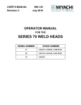
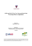
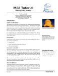
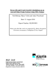
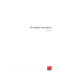
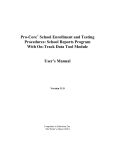
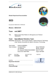
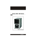
Versa® DRIVE C1
User Manual
July 18, 2006
Table of Contents
1.
2.
3.
Introduction _______________________________________________________________________ 3
Quick Start _________________________________________________________________________ 3
General Information _________________________________________________________________ 3
3.1 Front Panel _____________________________________________________________________ 3
3.2 Back Panel _________________________________________________________________________4
3.3 Firmware __________________________________________________________________________4
4. Setup ______________________________________________________________________________ 5
4.1 Mounting______________________________________________________________________ 5
4.2 Connections ___________________________________________________________________ 5
4.3 Compact Flash Cards _____________________________________________________________ 6
4.3.1 CF Card Formatting ______________________________________________________________ 6
5. Versa DRIVE Menu System ____________________________________________________________ 7
5.1 Navigation_____________________________________________________________________ 7
5.2 Selecting Modes and Modifying Parameters ___________________________________________ 7
5.3 Modes _________________________________________________________________________ 7
5.3.1 Pattern_________________________________________________________________________ 8
5.3.2 Playback _______________________________________________________________________ 8
5.3.3 ID_____________________________________________________________________________ 9
5.3.4 Resolution ______________________________________________________________________ 9
5.3.5 Brightness ______________________________________________________________________ 9
5.3.6 Red, Green, and Blue Balance _______________________________________________________ 9
5.3.7 Firmware _______________________________________________________________________ 9
5.3.8 Link (Master / Slave)_______________________________________________________________ 9
6. Contact Closure ____________________________________________________________________ 10
7. DMX Control ________________________________________________________________________ 10
7.1 DMX Start Address______________________________________________________________ 11
7.2 DMX Resolution _______________________________________________________________ 11
7.2.1 High Resolution _________________________________________________________________ 11
7.2.2 Low Resolution _________________________________________________________________ 11
7.3 Playback Mode _________________________________________________________________ 12
8. Direct Color ________________________________________________________________________ 13
9. Link (Master / Slave) _________________________________________________________________ 13
10. Engineering Mode ___________________________________________________________________ 14
11. Specifications ______________________________________________________________________ 15
12. Contacting Element Labs ____________________________________________________________ 16
© 2004 - 2006 Element Labs, Inc. All rights reserved.
The Element Labs logo, Versa DRIVE , and RasterMAPPER are trademarks of Element Labs, Inc.
Other trademarks and trade names may be used in this document to refer products by other entities.
Element Labs, Inc. claims no proprietary interest in trademarks and trade names owned by others.
Information and specifications in this document are subject to change without notice.
Element Labs, Inc. assumes no responsibility or liability for any errors or inaccuracies that may appear in this manual.
Revised July 18, 2006
Page 2 of 16
Versa DRIVE C1
User Manual
1. Introduction
The Versa® DRIVE C1 is a stand-alone controller for Versa TILE and Versa TUBEs. AVI or BMP based patterns are
combined with a pixel map in the RasterMAPPER™ software application, saved onto a Compact Flash card, and
loaded into the C1. Playback is via front panel controls, DMX, or contact closure.
2. Quick Start
1.
Connect Power & Data Cables. Use the Local or Serial Data output to connect to your Versa TILE or TUBE
system.
2.
Create a map of your system in RasterMAPPER.
3.
Import .AVI videos or .BMP still images into RasterMAPPER to create patterns.
4.
Output the patterns as .CFF files and store them on a Compact Flash (CF) card.
5.
Insert the CF card into the C1 and turn the power on.
6.
Use the MODE, UP (Λ), and DOWN (V) buttons to select different patterns and playback modes.
3. General Information
3.1 Front Panel
Versa DRIVE C1
888
COMPACT FLASH
MODE
UP
DOWN
POWER
The Versa DRIVE C1 has the following controls and displays on its front panel:
•
•
•
•
Three function buttons: MODE, UP (Λ) and DOWN (V)
Compact Flash Card Slot
3 Digit Numeric LED Display
POWER switch
Revised July 18, 2006
Page 3 of 16
Versa DRIVE C1
User Manual
3.2 Rear Panel
AC Power Input
Contact
Closure
DMX
In
DMX
Out
Local Data
Output
Serial Data
Output
The Versa DRIVE C1 has the following connectors on its rear panel:
•
•
•
•
•
•
AC Power Input (85-264VAC, 50/60Hz)
Contact Closure Input
DMX Input
DMX Output (thru)
Local Data Output
Serial Data Output
Male IEC Connector
Female DB-9 Connector
Male 5 pin XLR
Female 5 pin XLR
Female 4 pin XLR
Female 6 pin XLR
3.3 Firmware Versions
The standard version of firmware supports 1,024 pixels and 2048 pixels. (See Engineering section) The
tradeoff for doubling the pixel output is a reduced response time to some commands and internal
functions.
Changing firmware involves replacing two IC chips on the C1’s motherboard. This process can be done by
the end user, dealer, or at Element Labs. Please contact your dealer or Element Labs for more information.
The Current Firmware is Version 5-1.
Revised July 18, 2006
Page 4 of 16
Versa DRIVE C1
User Manual
4. Setup
4.1 Mounting
The C1 is equipped with four plastic feet for tabletop operation. If necessary, the feet can be easily
removed. Pry the center peg up with a small screwdriver and then pull the foot out of its mounting hole.
The C1 can be rack mounted with the included accessories. Each rack ear attaches to the side of the C1
enclosure with four 3mm screws (included).
There are three possible configurations for rack mounting
One short and one long rack ear with C1 on left side:
Versa DRIVE C1
888
COMPACT FLASH
M ODE
UP
DOWN
POWER
One short and one long rack ear with C1 on right side:
Versa DRIVE C1
888
COMPACT FLASH
MODE
UP
DOWN
POWER
Two C1s with two short rack ears:
Versa DRIVE C1
Versa DRIVE C1
888
COMPACT FLASH
888
MODE
UP
DOWN
POWER
COMPACT FLASH
MODE
UP
DOWN
POWER
For the above configuration, open the tops of both C1s and use the 4mm screws and locknuts (included) to
attach the two C1 enclosures together.
4.2 Connections
1.
Connect the data output cable from the back of the C1 into the first Versa TUBE or TILE.
• The Serial and Local Data Outputs send identical data.
• The Serial Data Output may be connected to a Versa TILE panel, TUBE, RAY, or Buffer Box up to
100m away.
• The Local Data Output may be connected directly to the data input of a Versa TUBE or Versa
TILE X2, or Versa RAY up to 3m away.
2.
Connect AC power from an outlet to the Versa DRIVE C1.
4.
Insert a Compact Flash card into the slot on the front of the C1.
5.
Power on Versa DRIVE C1.
Revised July 18, 2006
Page 5 of 16
Versa DRIVE C1
User Manual
4.3 Compact Flash Cards
The Versa DRIVE C1 reads CompactFlash® cards. System mapping and pattern creation are executed in the
RasterMAPPER™ software and copied to a CompactFlash card for use in the Versa DRIVE C1.
The Versa DRIVE C1 is compatible with any size (32MB to 2GB) Type I or Type II CompactFlash card. The
number, and size, of patterns that are capable of being stored is dependant on the memory size of the
CompactFlash Card used.
4.3.1 CF Card Formatting
To be used in a Versa DRIVE C1 a CompactFlash(CF) card must be PC Formatted to the FAT32 File System
To Format a CompactFlash card:
1.
Right-click on ‘My Computer’
2.
Click ‘Manage’
3.
Click on ‘Disk Management’ from the list in the left-hand window
4.
From the list on the right select the drive letter for your CF card
5.
Right-click on the CF Card and choose ‘Format’
6.
Choose ‘FAT 32’ for the file system and click ok
Revised July 18, 2006
Page 6 of 16
Versa DRIVE C1
User Manual
5. Menu System
5.1 Navigation
The C1 can be controlled from the front panel with a simple menu system. A three digit numeric LED
display shows the current menu item and its value.
Navigation is done with the three buttons:
MENU – Steps forward through the menu modes.
UP (Λ) – Steps up through available menu items or parameter values. Press and hold for rapid scrolling.
DOWN (V) – Steps down through menu items or parameter values. Press and hold for rapid scrolling.
5.2 Selecting Modes and Modifying Parameters
To change the value for a parameter:
1.
Press MODE to scroll through the modes. The LED display will show the name of the mode and
then after two seconds will change to display the mode’s current value.
2.
When a new mode is selected, the UP (Λ) or DOWN (V) button can be pressed once, immediately to
display the current value. You do not need to wait for the display to change to the mode’s value.
3.
Press the UP (Λ) and DOWN (V) buttons to adjust the mode value.
The numeric values can roll-over in either direction betweenthe lowesst and highest values.
4.
Press MODE again to save the new value and proceed to the next mode.
After short period of inactivity (about 15 seconds), the UP (Λ) and DOWN (V) buttons go into the Lock
mode, and are disabled. This prevents accidentally changing of parameter values. If the UP (Λ) or
DOWN (V) buttons are pressed while the C1 is in Lock mode, the display will show LOC.
Pressing the MODE button immediately unlocks the C1. When the C1 is unlocked, it immediately goes
into the PATTERN mode: PAt.
While in the Lock mode, the display will revert to showing the current pattern number after a two
second delay.
5.3 Modes
When the MODE button is pressed, the C1’s display will advance to the next mode.
The Versa DRIVE C1 modes are as follows:
Pat (Pattern): Selects the current pattern from 0-255
PLA (Playback): Sets the playback mode to LOOP, HOLD, ONCE, BOUNCE, ALL, or PAUSE.
ID (ID): Selects the DMX start address from 0-512
res (DMX Resolution): Sets the DMX resolution mode to either HIGH or LOW.
brt (Brightness): Sets the output brightness level from 1 to 10
rb (Red Balance): Sets the White Balance level for Red from 0-63
Gb (Green Balance): Sets the White Balance level for Green from 0-63
bb (Blue Balance): Sets the White Balance level for Blue from 0-63
F#(Firmware): Displays the C1’s firmware version
Lnk (Link): Sets the Master / Slave Link Mode to either MASTER, SLAVE, or OFF
Revised July 18, 2006
Page 7 of 16
Versa DRIVE C1
User Manual
5.3.1 Pattern Pat
The C1 can use up to 255 individual patterns. Patterns 0, 254, and 255 are fixed in the C1’s firmware and
cannot be changed. Patterns 1 – 253 are user-definable and stored on the compact flash card.
Pattern 0:
Black
Patterns 1 – 253:
User-definable
Patterns created in RasterMAPPER and stored on the Compact Flash card.
The filename format is ###XXXXXX.cff (eg. 001MyTestPattern.cff)
### is three numeric digits from 001 through 253.
XXXXXX is any number of alphanumeric characters. These are ignored by the
controller.
.cff is the file extension (compact flash format).
Pattern 254: Test Pattern / Moving Pixel ID
Pattern 254 sets all pixels to black and then sequentially sets one pixel at a time to
white. This is useful for troubleshooting addressing or wiring problems.
NOTE: Test pattern 254 cycles sequentially through all 1024 (or 2048) pixels, so it can
take quite some time to complete. If you have a small system with less than1024 (or
2048) pixels, you will see no change in your fixtures after the last pixel is flashed until
the pattern completes and starts over again. You can reselect the pattern or reset the
controller to start the pattern over again without waiting.
Pattern 255: Test Pattern / Solid Colors
Pattern 255 cycles the entire output through red, blue, green, white, odds (odd
numbered pixels in white, even numbered pixels in black), and evens (the inverse of
odds).
By default, when the C1 is powered on, it will resume playing the same pattern that was active when the
controller was last turned off.
5.3.2 Playback PLA
The C1 can playback a pattern in any of six different modes:
• Loo (LOOP): The pattern continuously loops, starting over at frame 1 immediately after the last
frame.
•
hld (HOLD): The pattern plays once until the end, and then freezes on the last frame of the
pattern. The last frame is displayed until a new pattern is selected.
•
one (ONCE): Similar to HOLD, the pattern plays once until the end. After the last frame, the
output is set to black and remains black until a new pattern is selected.
•
bnc (BOUNCE): The pattern plays continuously forward, then backwards.
•
all (ALL): All user-defineable patterns are played sequentially. After the last pattern is
finished, the first pattern starts to play again.
•
PAU (PAUSE): The current pattern will pause, or freeze, in the current frame. The pattern will
resume when any of the five other playback modes are selected. This function is primarily for
Revised July 18, 2006
Page 8 of 16
Versa DRIVE C1
User Manual
use with a DMX console which can access the playback modes instantly.
5.3.3 ID ID
The ID mode sets the C1’s start address for the incoming DMX data. See the DMX section for details.
5.3.4 Resolution res
The Resolution mode sets the C1’s DMX resolution. See the DMX section for details.
5.3.5 Brightness brt
The C1 has a brightness level ranging from 1 (dimmest) to 10 (brightest). This can be used to match the
system output to low ambient light levels.
5.3.6 Red, Green, and Blue Balance rb, gn, bb
These three modes offer the ability to adjust the white balance color of the output by decreasing the
ouput for each primary LED color (Red, Green, and Blue). The default maximum level for each color is 63.
The range of possible values is from 0 – 63.
5.3.7 Firmware F
This mode displays the current firmware version of the C1. The UP (Λ) and DOWN (V) buttons have no
effect in this mode.
5.3.8 Link (Master / Slave) Lnk
The Link mode sets the type of control the Versa DRIVE has over a system.mMs (Master), SLA (Slave), and
0FF (OFF) are the three options. See the Link (Master / Slave) section for details.
Revised July 18, 2006
Page 9 of 16
Versa DRIVE C1
User Manual
6. Contact Closure
A “dry-contact“ is simply a normally open, single-pole, single-throw (SPST) switch or pushbutton, such as the
output side of a relay, etc.
The contact closure can be used to trigger playback of the first 8 user-defined patterns in the C1. It is not
restricted specifically to patterns 1 – 8. For example, if the lowest number pattern on the CF card is 17, then
contact closure #1 would trigger pattern 17.
The contact closure connector is a standard, commonly available DB-9.
Female DB-9
Pin #
1
2
3
4
5
6
7
8
9
Function
Pattern A – the lowest numbered user-defined pattern
Pattern B
Pattern C
Pattern D
Pattern E
Pattern F
Pattern G
Pattern H – the 8th lowest user-defined pattern
Common (+5VDC)
The contact closures use 5VDC at 1mA per closure. A dry contact switch can be connected at a distance of up to
1,000 meters using 24 AWG wire.
!
WARNING: Never connect any external voltage source to the Contact Closure DB9 connector.
Revised July 18, 2006
Page 10 of 16
Versa DRIVE C1
User Manual
7. DMX Control
The C1 requires 6 channels of DMX for Pattern, Playback, and Direct Color modes:
DMX CH
1
2
3
4
5
6
FUNCTION
Pattern Select
Playback Mode
Direct Color Mode (0%-25% is additive, 26%-75% undefined, 76%-100% is subtractive)
Direct Color Red
Direct Color Green
Direct Color Blue
NOTE: Link Mode must be set to Master for the C1 to send and recieve DMX data.
7.1 DMX Start Address
Set the ID (ID) value to the desired DMX start address from 1 to 512.
Example: If the ID=5, then that C1 would use DMX channels 5 through 10.
Set the ID to 0 (zero) to ignore all DMX input.
7.2 DMX Resolution
The C1 supports two different DMX resolutions: xi (High) and lo (Low). This only affects how the C1
interprets pattern selection on DMX input channel 1.
7.2.1 High Resolution
In High resolution mode, DMX channel 1 accesses all of the available patterns from 0 to 255. Set the decimal
value of the DMX channel to the value of the pattern that you want to play.
Example: DMX channel 1 @ 178 Ö C1 plays pattern #178
If no pattern number exists that matches the DMX value, no action is taken.
Revised July 18, 2006
Page 11 of 16
Versa DRIVE C1
User Manual
7.2.2 Low Resolution
In Low resolution mode, DMX channel 1 is divided into 20 steps. Each step will playback one of the 20 lowest
numbered user defined patterns. Note: this does not strictly mean patterns #001 through #020. low resolution
mode accesses the first 20 patterns on the CF card, regardless of their actual numbers.
DMX %
0%
5%
10%
15%
20%
25%
30%
35%
40%
45%
50%
DMX Decimal Value
0-3
9 - 16
22 - 29
35 - 42
48 - 55
60 - 67
73 - 80
86 - 95
99 - 106
111 - 118
124 - 131
Pattern
0 (black)
1st
2nd
3rd
4th
5th
6th
7th
8th
9th
10th
DMX %
55%
60%
65%
70%
75%
80%
85%
90%
95%
100%
DMX Decimal Value
137 - 144
150 - 157
163 - 170
175 - 182
188 - 195
201 - 208
213 - 220
226 - 233
239 - 246
252 - 255
Pattern
11th
12th
13th
14th
15th
16th
17th
18th
19th
20th
Pattern 0 (default blackout) is also available. The two test patterns #254 and #255 are not available.
Low resolution mode is useful for DMX consoles with limited capabilities (i.e. – if the ouput can only be
programmed in percentage, not decimal values).
There are also five or six null DMX values between each step. These prevent accidental fluctuation between
adjacent steps.
7.3 Playback Mode
DMX channel 2 selects the Playback mode.
DMX VALUE
0-50
51-100
101-150
151-200
201-255
Revised July 18, 2006
Page 12 of 16
PARAMETER
Loop
Hold
Once
Bounce
All
Versa DRIVE C1
User Manual
8. Direct Color
The Versa DRIVE C1 offers a unique feature called "Direct Color."
Using DMX channels, over 16 million solid colors can be mixed and output by the C1. In addition, these colors
can be added to or subtracted from any of the patterns, in effect, colorizing the output.
DMX CH
3
4
5
6
FUNCTION
Direct Color Mode (0%-25% is additive, 26%-75% undefined, 76%-100% is subtractive)
Direct Color Red
Direct Color Green
Direct Color Blue
The Direct Color function has two modes: additive and subtractive.
In the additive mode, the Direct Color values for are added to the color values in the pattern.
In the subtractive mode, the Direct Color values for are subtracted from the color values in the pattern.
There are three main uses for this function:
1.
When used with Pattern 0 (Black) in the additive mode, then it is possible to create any solid color on
the entire system of tiles or tubes.
Likewise, it can be used in subtractive mode with a user-defined all white pattern to achieve the same
effect.
2.
When used with a pattern, it will colorize the original video clip.
For example, the original pattern is white text scrolling across a black background. Using the subtractive
mode to remove the blue and green, the final output would be red text scrolling on a black
background. Alternately, in additive mode, adding red would create white text scrolling accross a black
background.
3.
This function can also be used to fade a pattern in or out, to either black or white.
9. Link (Master / Slave)
The C1 has a Master and Slave mode allowing multiple C1s to be controlled by one master. To link C1s together
use the DMX output. Attach the DMX Output to the DMX input of the next unit. XX units can be chained
together. Front panel and DMX information is transmitted through a system of C1’s.
9.1 Link Off
When link is set to off NO DMX will be sent by the C1. The C1 acts as a stand-alone unit.
9.2 Master Mode
When the C1 is in Master Mode all of the front panel selection will be duplicated on all Slave C1’s. Incoming DMX
data will also be resent to all slave C1’s
A dot will appear after the first chacter to indicate that the unit is in master mode.
Revised July 18, 2006
Page 13 of 16
Versa DRIVE C1
User Manual
9.3 Slave Mode
When a C1 is in slave mode is will duplicate all front panel and DMX commands that are sent to the master C1.
10. Engineering Mode
The Versa DRVIE C1 is equipped with an Engineering Mode for modifying low level paramters of the device.
Engineering Mode is most frequently used to adjust the output length of the data that the C1 generates from
1024 pixels (its default output length) to 2048 pixels.
To enter Enginering Mode:
1.
2.
Goto Firmware (F#)menu and hit up
Press the up and down buttons and hold for 5 seconds.
The three decimal points on the display with blink to indicate that you are in engineering mode.
The first menu option will appear on screen for about 5 seconds.
Hitting the mode button will go to the next menu option
To exit Engineering Mode press Mode and Up buttons simultaneously
10.1 Output out
The first menu option is output setting, either 1 or 2.
A setting of 1 indicates that the C1’s output is set for 1024 pixels.
A setting of 2 indicates that the C1’s output is set for 2048 pixels.
Ensure that all buffer boxes, include all those include with a Vera TILE system are set to D1 mode, or 1024 pixels.
10.2 Balance Enable ben
Not Implemented
10.3 Balance bal
Not Implemented
10.4 Error Code cod
Not Implemented
Revised July 18, 2006
Page 14 of 16
Versa DRIVE C1
User Manual
11. Specifications
Part Number VD-C1
Width
Height
Depth
Weight
Construction
Mounting
Environmental
Cooling
Storage Temperature
Operating Temperature
Operating Humidity
1/2 standard rack unit (19.0” / 430mm)
1U (1.75” / 44.4mm)
12” (304.8mm)
160.2 oz 10.0125 lbs = 4.542 kg
Powder Coated Steel
Stand alone with plastic feet or rack mounted with included rack ears
IP30 (indoor use only)
Passive
-40°C to 70°C
0°C to 50°C
10% to 85%, non condensing
Front Panel Power Switch
LED Display
3 control buttons - Mode, Up, Down
Compact Flash Slot
Rear Panel AC Power: 100-240 VAC 50/60Hz (female IEC connector)
Serial Data output for Versa fixtures (female XLR, 6-pin)
Local Data output for Versa fixtures (female XLR, 4-pin)
DMX input (male XLR, 5-pin)
DMX ouput (female XLR, 5-pin)
Contact Closure (female DB-9)
Output Data 1,024 pixel output on Serial Data and Local Data ports simultaneously
2,048 pixel output with optional v2-4 firmware
Data Output Rate 30 FPS (frames per second) maximum output rate
Included Accessories Rack mounting ears and hardware (one long ear, one short ear)
Hardware for attaching two C1s in a single rack space
WARNING Severe risk of electric shock. No user-serviceable parts inside.
Information and specifications in this document are subject to change without notice.
Element Labs, Inc. assumes no responsibility or liability for any errors or inaccuracies that may appear in this manual.
Revised July 18, 2006
Page 15 of 16
Versa DRIVE C1
User Manual
12. Contacting Element Labs
www.elementlabs.com
[email protected]
Element Labs, Inc.
9421 Neils Thompson Drive
Austin, TX 78758 USA
+1 512 491 9111 tel
+1 512 491 9122 fax
Element Labs GmbH
Lindener Str. 15
D-38300 Wolfenbüttel
Germany
+49 5331 905660 tel
+49 5331 905661 fax
Revised July 18, 2006
Page 16 of 16
Versa DRIVE C1
User Manual