1
C-Scape Manual
Sensors
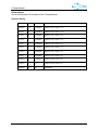
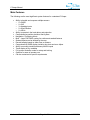
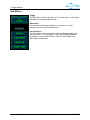
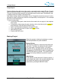
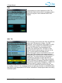
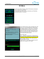
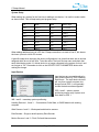
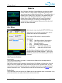
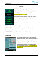
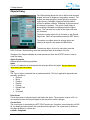
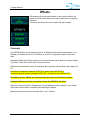
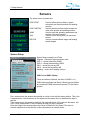
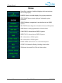
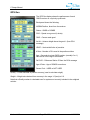
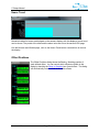
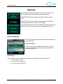
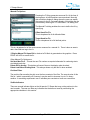
The sensor menu is shown here.
POS SETUP
POS CONTROL
WIND
VRU
R/B SYS
Used to define antenna offsets, system
accuracies and fixed corrections for heading
sensors.
Used to determine which active sensors are
used in the position and heading solution.
Used to setup the operating parameters and
location of the wind sensors.
Used to set the active pitch, roll and heave
sensor.
Used to set and calibrate range and bearing
system targets.
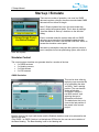
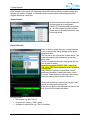
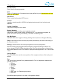
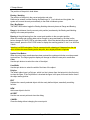
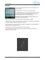
Sensor Setup
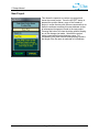
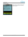
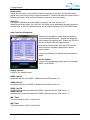
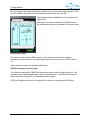
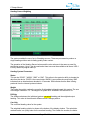
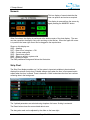
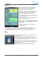
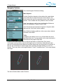
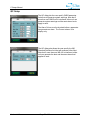
Sensor Setup currently has 6 Tabs.
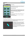
Diagram – Shows the sign convention used
GPS 1 – shows the primary GNSS
GPS 2 – shows the secondary GNSS
INS 1 – shows the primary INS
INS 2 – shows the secondary INS
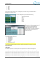
Heading – covers all 3 heading sources
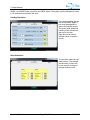
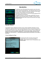
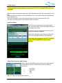
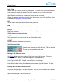
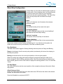
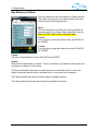
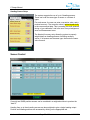
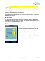
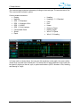
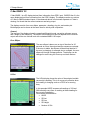
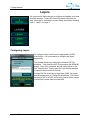
GNSS 1 and GNSS 2 Setup
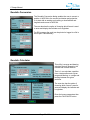
These two tabs are identical, but refer to GNSS 1 or 2.
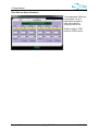
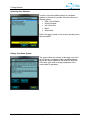
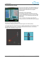
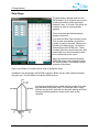
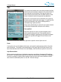
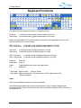
GNSS antenna offsets and Range / Bearing sensor offsets
are measured FROM the Antenna (sensor) TO the Datum
position.
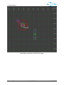
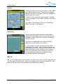
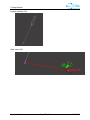
First, measure from the antenna across-ship to a point in line with the datum position. This is the
X measurement. If the direction from the antenna to the datum line is to starboard the sign is
positive.
Then measure from the antenna, parallel to the longitudinal axis of the vessel to the datum, this
is the Y axis measurement. If this is towards the stern the sign is negative.
Enter the height of the antenna above the Center of Rotation of the vessel. This value is
normally negative since the direction of the measurement is normally down.
Version 1.10
Page 51 of 86
11/26/2012