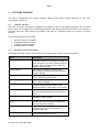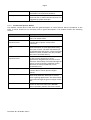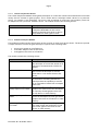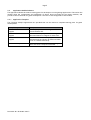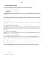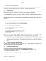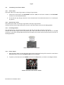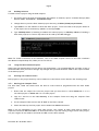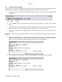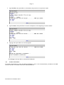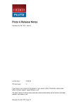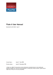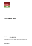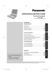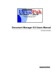
1
Pluto 6 Development Kit
User Manual
Document No. 80-18463 Issue 2
Current Issue :-
Issue 2, 7 July 2008
Previous Issues :-
Issue 1, 22 November 2005
© Heber Ltd. 2008. This document and the information contained therein is the intellectual
property of Heber Ltd. and must not be disclosed to a third party without consent. Copies may be
made only if they are in full and unmodified.
If your query is not covered in this User Manual, or you require further information, please email
Heber Customer Support: [email protected]
The latest version of this User Manual and other technical information can be found on the Heber
website: www.heber.co.uk
Copyright © Heber Ltd. 2008. All rights reserved. This document and the information contained
therein is the intellectual property of Heber Ltd. and must not be disclosed to a third party without
consent. Copies may be made only if they are in full and unmodified.
The information contained in this User Manual is believed to be accurate and reliable. However,
Heber Ltd. assumes no responsibility for its use, and reserves the right to revise the documentation
without notice.
Precise specifications may change without prior notice.
All trademarks are acknowledged.
HEBER LIMITED
Belvedere Mill
Chalford Stroud
GL6 8NT
UK
Tel +44 (0) 1453 886000
Fax +44 (0) 1453 885013
Email
[email protected]
Website www.heber.co.uk
Document No. 80-18463 Issue 2
Page i
CONTENTS
1
INTRODUCTION......................................................................................... 1
1.1
PLUTO 6 DOCUMENTATION ................................................................................. 1
1.1.1 Viewing the Pluto 6 Documentation ............................................................. 1
1.2
SYSTEM REQUIREMENTS ..................................................................................... 1
1.3
DEVELOPMENT KIT CONTENTS .............................................................................. 1
2
SOFTWARE OVERVIEW ................................................................................ 2
2.1
SOFTWARE LIBRARIES ....................................................................................... 2
2.1.1 Hardware Abstraction Module .................................................................... 2
2.1.2 Standard Peripherals Module ..................................................................... 3
2.1.3 Custom Peripherals Module ....................................................................... 4
2.1.4 Standard Interface Module ........................................................................ 4
2.2
APPLICATION MODULE SOFTWARE .......................................................................... 5
2.2.1 Application Examples .............................................................................. 5
3
DEMONSTRATION PROGRAMS........................................................................ 6
3.1
DEMONSTRATION PROGRAM ................................................................................. 6
3.1.1 Audio Samples ....................................................................................... 6
3.2
DUAL VIDEO DEMONSTRATION PROGRAM .................................................................... 6
3.2.1 Video Demonstration Images...................................................................... 6
3.3
TOUCHSCREEN DEMONSTRATION PROGRAM ................................................................. 6
3.4
BOOT LOADER PROJECT .................................................................................... 6
4
USING THE DEVELOPMENT KIT ...................................................................... 7
4.1
INSTALLING MANUALLY ..................................................................................... 7
4.2
INSTALLING THE COMPACT FLASH READER/WRITER ......................................................... 7
4.3
INSTALLING ADOBE ACROBAT READER ...................................................................... 7
4.4
CONNECTING YOUR PLUTO 6 BOARD ....................................................................... 8
4.4.1 Serial Cable .......................................................................................... 8
4.4.2 Parallel Port Cable ................................................................................. 8
4.4.3 ICD Debug Module................................................................................... 8
4.4.4 Power Supply ........................................................................................ 8
4.5
BUILDING SOFTWARE ....................................................................................... 9
4.6
USING THE DEMONSTRATION PROJECTS ..................................................................... 9
4.7
RUNNING YOUR CODE ON PLUTO 6 ......................................................................... 9
4.7.1 Running from Compact Flash ..................................................................... 9
4.8
USING THE P&E ICD DEBUGGER .......................................................................... 10
4.9
FURTHER INFORMATION ................................................................................... 11
Document No. 80-18463 Issue 2
Page ii
This page intentionally left blank.
Document No. 80-18463 Issue 2
Page 1
1
INTRODUCTION
This User Manual describes how to use the Pluto 6 Development Kit in a development environment. The User
Manual gives an overview of the software that is included with the Pluto 6 Development Kit. The User Manual
also describes how to use the demonstration programs that are also included.
1.1
Pluto 6 Documentation
Hardware documentation for Pluto 6 is covered in a separate User Manual.
Refer to: 80-16322 - Pluto 6 User Manual.
Software documentation for Pluto 6 is covered in a separate Compiled Help file.
Refer to: 80-17314 - Pluto 6 Software User Manual.
These manuals are included on the Pluto 6 Development Kit CD-ROM. The latest versions of these manuals
are also available on the Heber website (http://www.heber.co.uk).
1.1.1
Viewing the Pluto 6 Documentation
The Pluto 6 Software documentation is supplied in Compiled Help format. After the Development Kit
software has been installed the Compiled Help file can be accessed through the PC Start menu.
To open the Compiled Help file, click: Start - Programs - Pluto 6 - Pluto 6 Software Help.
All of the Pluto 6 documentation can also be found in the C:\heber\pluto6\documentation directory on the
PC where the Development Kit is installed.
1.2
System Requirements
PC running Windows® 2000 or XP.
Note: Windows® 95, 98, NT, or ME are not supported.
1.3
Development Kit Contents
The Pluto 6 Development Kit contains the following items:
Part No.
01-17862
01-16443
01-18012
63-82513
63-82514
01-16607
21-18535
63-82516
61-14620
31-81194
63-81647
63-82413
63-82256
Description
Pluto 6 Dual Video Debug Board
2 off Calypso 32 Video cards (2nd Calypso 32 card is located behind the CD case)
Pluto 6 Dual Video Development Kit CD-ROM with Pluto 6 Development Kit Software
P&E ColdFire® Shielded BDM Interface Module
P&E ColdFire® Debug Software
Pluto 6 Evaluation Board
256MB Compact Flash Card containing Demonstration Software
Belkin USB Compact Flash Card Reader/Writer
2 off 25-way D-Type Serial Cables
25 to 9-Way D-Type Converter
FPGA Extractor
Development Kit ATX PSU
Power Supply Cable
Document No. 80-18463 Issue 2
Page 2
2
SOFTWARE OVERVIEW
The Pluto 6 Development Kit includes software libraries that enable a game developer to start their
development on Pluto 6.
2.1
Software Libraries
The Pluto 6 software libraries are organised into modules. Each of the modules provides a set of device
drivers each with an Application Programming Interface (API) that provides functions that are accessible to
the game developer. Each module is provided in the form of a compiled archive for inclusion in a game
project.
The following modules are provided:
•
•
•
•
2.1.1
Hardware Abstraction Module
Standard Peripherals Module
Custom Peripherals Module
Standard Interface Module
Hardware Abstraction Module
This module provides an API to access the Pluto 6 hardware and contains the following drivers:
Driver
Description
Advanced Video Driver
The Advanced Video Driver allows the
advanced features of the Calypso 32 graphics
driver software to be used, including support
for Dual Video systems where 2 Calypso 32
graphics cards are used.
Multiplex Driver
The multiplex module is a device driver
controlling the multiplexed lamps and seven
segment displays.
Multiplexed Inputs
The Multiplexed Inputs module is a device
driver controlling system inputs.
Outputs Driver
The Outputs Driver allows the control of the
Pluto 6 system outputs.
Serial Communications Driver
The Serial Communications Driver allows
access to the services of multiple serial
devices available on the Pluto 6 control board.
PIC18 Driver
The PIC18 Driver provides functions to access
data on the PIC18 Customer Security Device
(CSD).
M-Bus (I2C) Driver
The M-Bus Driver provides an I2C interface on
the Pluto 6 control board.
Vacuum Fluorescent Display
Driver
The Vacuum Fluorescent Display (VFD) Driver
provides low level functions for addressing
vacuum fluorescent displays.
ATA Driver
The ATA Driver provides the low level
functions to access an ATA hard disk or
Compact Flash card.
Device Manager
The Device Manager provides the functionality
for manipulating device drivers.
Document No. 80-18463 Issue 2
Page 3
Entry Module
The Entry module provides the low-level
initialisation of the Pluto 6 hardware.
Interrupt Module
The Interrupt Module provides functionality to
allow the user to install functions that will run
triggered by system interrupts
2.1.2
Standard Peripherals Module
This module contains drivers that allow the game developer to control devices that are peripheral to the
Pluto 6 control board but are commonly used in game development. The module contains the following
drivers:
Driver
Description
Timer Driver
The timers module provides an API to use the
Pluto 6 on board timers.
Generic Touch Screen
Controller Driver
The Generic touch screen driver provides a
common API to specific touch screen
controllers.
ELO Touch Screen Controller
Driver
The ELO touch screen driver provides an API to
allow developers to write applications using
ELO touch screens. The basic functionality is
accessed through the generic touch screen API.
Advanced control functions are also provided
that can be accessed directly.
Microtouch Touch Screen
Controller Driver
The Microtouch touch screen driver provides
an API to allow developers to write
applications using Microtouch touch screens.
The basic functionality is accessed through the
generic touch screen API. Advanced control
functions are also provided that can be
accessed directly.
Generic Stepper Motor Driver
The Generic Stepper Motor driver provides a
common API to control specific stepper
motors.
Reel Stepper Motor Driver
The Reel Stepper Motor driver is a specialised
driver that allows the developer to control
reels in gaming applications. The functionality
is accessed through the generic stepper motor
API.
E2ROM Driver
The E2ROM driver module provides functions to
read from and write data to the EEPROM
Device optionally fitted to the Pluto 6 board.
Document No. 80-18463 Issue 2
Page 4
2.1.3
Custom Peripherals Module
The Custom Peripherals Module allows games developers to create their own drivers and build them into GNU
library files for inclusion in game projects. This is useful where a developer needs a driver for a particular
device, for example a coin mechanism. The source code is supplied for all drivers in this module, which can
be adapted to suit a particular hardware device. The module contains the following drivers:
Driver
Description
RM161680
This is the ramp table and definitions for
a Starpoint RM161680 reel and can be
used as a template from which to derive
ramp tables for other types of reels.
2.1.4
Standard Interface Module
This module provides interface drivers that use the services of lower level device drivers. The drivers provide
a simple interface to allow the game developer to perform the following tasks:
•
•
•
Access a file system on an ATA device
Load audio samples from an ATA device
Load graphics files from an ATA device
The module contains the following drivers:
Driver
Description
FAT32 Driver
The FAT32 driver provides an API to allow
the developer to access files stored on an
ATA device formatted with a FAT32 file
system.
Streamed Audio Driver
The Streamed Audio driver provides an
API to allow the developer to stream
audio files in .wav format from an ATA
device.
Heber Sound File Audio Driver The Heber Sound File (HSF) audio driver is
an alternative streaming sound driver,
which provides the capability to stream
up to 4 channels of audio from a Compact
Flash card.
Microsoft® Windows® BMP
Bitmap Graphics File Loader
The Microsoft® Windows® BMP bitmap
graphics file loader allows the developers
to load .bmp format graphics files from
an ATA device to video memory.
TGA Bitmap Graphics File
Loader
The TGA bitmap graphics file loader
allows the developers to load .tga format
graphics files from an ATA device to video
memory.
Heber Image Format Graphics The Heber Image Format (HIF) graphics
File Loader
file loader allows the developers to load
.hif format graphics files from an ATA
device to video memory.
Document No. 80-18463 Issue 2
Page 5
2.2
Application Module Software
The Application Module Provides a starting point for developers to write gaming applications. Files within the
module allow the configuration and installation of device drivers provided by the library modules, and
provide a basic framework for game development. The source code is supplied for this module.
2.2.1
Application Examples
The following example applications are provided that can be used as a template/starting point for game
development:
Example Project
Description
Standard Demonstration
Program
Standard project demonstrating use of the
Pluto 6 software API.
Dual Video Demonstration
Program
Dual screen video project demonstrating
advanced features of Calypso 32 video card.
Touchscreen Demonstration
Program
Touchscreen Demonstration project
demonstrating the Calypso 32 Advanced Video
Driver in a touchscreen setup.
Boot Loader Project
Boot loader project demonstrating loading
game code from a Compact Flash card.
Document No. 80-18463 Issue 2
Page 6
3
DEMONSTRATION PROGRAMS
The following demonstration programs are supplied with the Pluto 6 Development Kit:
•
•
•
•
Standard Demonstration Program
Dual Video Demonstration Program
Touchscreen Demonstration Program
Boot Loader
The demonstration programs give examples of how to use the API calls described in the Pluto 6 Software
User Manual.
3.1
Demonstration Program
The Standard Demonstration Program (demo.s19) is included on the Compact Flash card in the Development
Kit. The Standard Demonstration Program allows the user to test the hardware functionality of Pluto 6 using
the Heber software libraries. The program demonstrates the API functions that would typically be used in a
reel based application.
3.1.1
Audio Samples
Audio samples are supplied in the Demonstration Program. The audio files are loaded from the Compact
Flash card.
3.2
Dual Video Demonstration Program
The Dual Video demonstration program (vdemo.s19) is included on the Compact Flash card in the
Development Kit. The Dual Video demonstration program shows the use of the Calypso 32 Advanced Video
drivers in a dual screen setup and provides examples of techniques that are common to video gaming
applications.
3.2.1
Video Demonstration Images
The images used in all of the video demonstrations are in 24 bit per pixel Windows® bitmap (.bmp) format
and are loaded from the Compact Flash card.
3.3
Touchscreen Demonstration Program
The Touchscreen demonstration program shows the use of the Calypso 32 Advanced Video Driver in a
touchscreen setup and provides examples of techniques that are common to video gaming applications, for
example calibration and moving a sprite with the finger on screen.
3.4
Boot Loader Project
The Boot Loader is used to load and execute the demonstration programs. The Boot loader resides in the
Boot Flash which is fitted in socket U1 on the Pluto 6 control board and is automatically executed when the
Pluto 6 is powered up.
Note: All Compact Flash cards must be formatted with the FAT 32 File system and not the FAT file system.
Document No. 80-18463 Issue 2
Page 7
4
USING THE DEVELOPMENT KIT
Place the Pluto 6 Development Kit CD in the CD-ROM drive of your PC. The Setup program should run
automatically. If the CD-ROM does not install automatically, follow the instructions below.
4.1
Installing Manually
If the installation does not start automatically, double-click the CD Drive icon in My Computer, and then
double-click the Setup icon. Follow the on screen instructions to complete the installation.
It is recommended that you choose the Complete Installation and accept the Default Install Path. This will
create a c:\heber directory for the installation.
Following the installation you will be prompted to reboot your computer. It is recommended that you accept
this option because until your computer has been rebooted the paths required by the GNU compiler will not
be set up.
Once your computer has restarted, check that the paths have been set up correctly:
1. From the desktop, click: Start - Settings - Control Panel.
2. Double-click the System icon and choose the Advanced tab.
3. Click the Environment Variables button.
4. In the ‘System Variables’ section, select Path.
5. Click the Edit button.
6. The following paths should be appended to the path:
c:\heber\exe\gcc-m68k\bin
c:\heber\exe\cygnus\cygwin-b20\h-i586-cygwin32\bin
c:\heber\exe\utils
2000
copy
and
paste
the
following
Note:
If
you
are
using
Windows®
c:\heber\exe\gcc-m68k\bin;c:\heber\exe\cygnus\cygwin-b20\h-i586-cygwin32\bin;c:\heber\exe\utils
path:
7. Install the P&E In Circuit Debugger software. This software is supplied separately on the P&E
Software CD. Put the CD into your CD-ROM drive. If it does not start automatically, open the
CD-ROM drive and double-click the Setup icon to start the installation. It is recommended that you
install the P&E software onto drive C, as problems may be encountered if it is installed to a different
drive.
4.2
Installing the Compact Flash Reader/Writer
To install and use the Compact Flash card reader/writer refer to the manufacturer’s instructions on the
driver CD provided with the Pluto 6 Development Kit.
4.3
Installing Adobe Acrobat Reader
The documentation for the Pluto 6 is supplied in either Compiled Help or PDF format. In order to view the
PDF files you will need to have Adobe® Acrobat® Reader installed on your computer.
To install Adobe® Acrobat® Reader, double click on the AdbeRdr70_enu_full.exe icon in the
c:\heber\pluto6\adobe\reader\v7 directory.
Or download from: http://www.adobe.com/products/acrobat/readstep2.html
Document No. 80-18463 Issue 2
Page 8
4.4
Connecting Your Pluto 6 Board
4.4.1
Serial Cable
The serial cable is a 25 way D-Type male to 25 way D-Type female.
1. Connect the male end to the DATAPORT connector (P22) on the Pluto 6 board or the DATAPORT
connector on the Evaluation Board.
2. Fit the 25-to-9 way D-Type converter to the female end of the cable and connect it to a serial port
on your PC.
4.4.2
Parallel Port Cable
The parallel port cable is a 25 way D-Type male to 25 way D-Type female.
Connect the male end to the parallel port of your PC and the female end to the ICD Debug Module.
4.4.3
ICD Debug Module
The ICD module has a 25 way D-Type male at one end and a 26 way IDC connector at the other.
Connect the 25 way D-Type end to the parallel port cable and connect the 26 way IDC end to the BDM
connector on the Pluto 6 board (P4). Ensure that the module faces away from the Pluto 6 board, as shown in
the diagram below.
Pluto 6 BDM Module Connection
4.4.4
Power Supply
1. Plug the mains cable into the ATX power supply and connect the 20 way ATX connector to the Pluto 6
Evaluation Board. The green STAND BY LED will be illuminated.
2. To power up the board turn the POWER switch into the ON position, as shown in the diagram below.
Pluto 6 Evaluation Board Power Switch
Document No. 80-18463 Issue 2
Page 9
4.5
Building Software
To build a Pluto 6 project using the GNU compiler:
1. On the PC where the Pluto 6 Development Kit software is installed, open a Command Prompt (DOS)
Window (Start - Accessories - Command Prompt).
2. Change directory into the Pluto 6 demo project directory (C:\heber\pluto6\projects\demo)
3. Type make to run the makefile to build the demo project. To force a build of the project delete all
of the object files in the directory (touch *.c) and type make.
4. Type makemap demo (if building a standard non-video project) or makemap vdemo (if building a
dual video project) to create a map which can be read by the P&E debugger.
Note: For further information on the makefile, refer to the GNU Compiler section in the Pluto 6 Software
User Manual Compiled Help File (Heber part no. 80-17314).
4.6
Using the Demonstration Projects
When using the demonstration projects during you development, it is recommended that you make a copy of
the demo folder that you want to change. Any changes that you make should be made to the copied versions
of the demo projects.
4.7
Running Your Code on Pluto 6
Built projects in the project directory can be loaded on to the Pluto 6 control board in the following ways:
4.7.1
Running from Compact Flash
The boot flash, fitted into socket U1on the Pluto 6 control board is programmed with the boot loader
project.
1. Ensure that the output file from the project that you have built is called demo.s19 if it is a
non-video project or vdemo.s19 if it is a video project.
2. Copy the .s19 file to the root directory of the Compact Flash card using the Compact Flash
reader/writer.
3. Fit the Compact Flash card into the CF SLOT on the Pluto 6 board.
4. Power the board up and the project will be loaded into DRAM and execute.
Note: If you are attempting to run a dual video project, two Calypso 32 video cards must be fitted to
expansion connectors EXP 0 and EXP 1 on the Pluto 6 board. If you are running a single screen video project,
only one Calypso 32 card needs to be fitted into EXP 1 on the Pluto 6 board.
Document No. 80-18463 Issue 2
Page 10
4.8
Using the P&E ICD Debugger
Ensure that the ICD software is installed. The ICD software is on the P&E Software CD included with the Pluto
6 Development Kit. Ensure the debug module attached to both the Pluto 6 board and your PC.
1. Power up the Pluto 6 board and launch the P&E ICDCFZ ColdFire® ICD software. The following toolbar
is displayed:
2. Click the Reset button on the software tool bar to reset the ColdFire® processor on the Pluto 6
board.
3. Click the Go button on the software tool bar to execute the code in the boot flash. This code will run
the Pluto 6 entry code and set up the chip select registers on the ColdFire® processor.
4. After a few seconds click the Stop button on the software tool bar to stop the boot flash code
executing.
Note: Do not reset the CPU at this point because the chip select settings set by the boot flash code will be
cleared.
5. Click the Load button on the software tool bar, select the .s19 file that you wish to load (e.g.
demo.s19) and click Open. In the ICD software Status Window a Loading.... message will appear.
When the .s19 file has loaded a loaded message will appear in the Status Window:
6. Type pc entry, to set the program counter to the beginning of the program, then press Enter:
Document No. 80-18463 Issue 2
Page 11
7. Type SR 2700, then press Enter to reinitialise the processor to a supervisor mode:
8. Type br Game, then press Enter to reach a breakpoint at the beginning of function Game:
9. Type go, then press Enter to run the program:
The debugger will stop when it reaches the breakpoint.
4.9
Further Information
For further information on using the P&E ICD Debugger, refer to the documentation provided on the P&E
Software CD that is included in the Pluto 6 Development Kit.
Document No. 80-18463 Issue 2