1
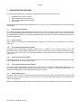
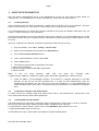
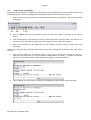
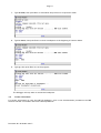
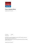
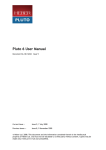
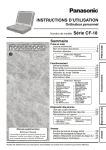
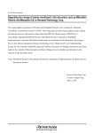
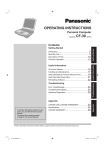
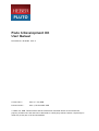
Page 8
4.4
Connecting Your Pluto 6 Board
4.4.1
Serial Cable
The serial cable is a 25 way D-Type male to 25 way D-Type female.
1. Connect the male end to the DATAPORT connector (P22) on the Pluto 6 board or the DATAPORT
connector on the Evaluation Board.
2. Fit the 25-to-9 way D-Type converter to the female end of the cable and connect it to a serial port
on your PC.
4.4.2
Parallel Port Cable
The parallel port cable is a 25 way D-Type male to 25 way D-Type female.
Connect the male end to the parallel port of your PC and the female end to the ICD Debug Module.
4.4.3
ICD Debug Module
The ICD module has a 25 way D-Type male at one end and a 26 way IDC connector at the other.
Connect the 25 way D-Type end to the parallel port cable and connect the 26 way IDC end to the BDM
connector on the Pluto 6 board (P4). Ensure that the module faces away from the Pluto 6 board, as shown in
the diagram below.
Pluto 6 BDM Module Connection
4.4.4
Power Supply
1. Plug the mains cable into the ATX power supply and connect the 20 way ATX connector to the Pluto 6
Evaluation Board. The green STAND BY LED will be illuminated.
2. To power up the board turn the POWER switch into the ON position, as shown in the diagram below.
Pluto 6 Evaluation Board Power Switch
Document No. 80-18463 Issue 2