1
FLAT PAR TRI18XS
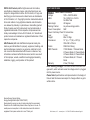
Photometric Chart
FLAT PAR TRI18XS
Set Up
POWER
POWER
Notice: Be sure to DMX512
follow figures two and three when making your own
cables. Do not DMX+,DMX-,COMMON
use the ground lug on the XLR connector. Do not connect the cable’s shield conductor to the ground lug or allow the shield
conductor to come in contact with the XLR’s outer casing. Grounding
the shield could cause a short circuit and erratic behavior.
COMMON
1
DMX512 OUT
3-PIN XLR
FLAT PAR TRI18XS
SOUND
REMOTE
CONTROL
INPUT
INPUT
OUTPUT
REMOTE
CONTROL
INPUT
Power Cord Daisy Chain
SOUND
1 Ground
FLAT PAR TRI18XS
3
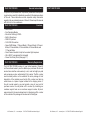
Fuse Replacement
Disconnect the unit from its power source. Remove the power cord
from the unit. Once the cord has been removed, you will find that the
fuse holder is located inside the power socket. Insert a flat-head screw
driver into the power socket and gently pry out the fuse holder. Remove
the bad fuse and replace with a new one. The fuse holder also has a
holder for a spare fuse.
ADJ Products, LLC - www.adj.com - FLAT PAR TRI18XS User Manual Page 17
2
SOUND
2 Cold
2 Cold
1 Ground
DMX512 IN
3-PIN XLR
REMOTE
CONTROL
INPUT
INPUT
3
Figure 2
OUTPUT
1
2
Termination redu
avoids signal tra
and interference.
to connect a DMX
120 Ohm 1/4 W)
and PIN 3 (DMX
XLR Pin Configuration
Pin 1 = Ground
Figure 3
3 Hot
Pin 3 = Data True (positive)
POWER
POWER
Special Note: Line Termination. When longer runs of cable are
Installation
2
DMX -
1
XLR Female Socket
3 Hot
DMX512
DMX+,DMX-,COMMON
1
3
Pin 2 = Data Compliment (negative)
POWER
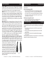
The FLAT PAR TRI18XS is fully operational in three different mounting positions, hanging upside-down from a ceiling, hanging sideways
on trussing, or set on a flat level surface. The unit should be mounted
using a mounting clamp (not provided), affixing it to the mounting
bracket that is provided with the unit. Always ensure that the unit
is
COMMON
firmly fixed to avoid vibration and slipping while
operating.
Always
DMX
+
DMX512 OUT
3-PIN XLR the unit is secure
DMX ensure that the structure to which you are attaching
and is able to support a weight of 10 times the unit’s weight. Also,
always use a safety cable that can hold 12 times the weight of the
unit when installing the fixture.
The equipment must be installed by a professional, and it must be
installed in a place where it is out of the reach of people’s grasp.
2
OUTPUT
XLR Male Socket
With this feature you can connect the fixtures to one another
using the IEC input and output sockets. The quantity that can be
connected is 10 fixtures maximum. After 10 fixtures you will need
to use a new power outlet. They must be the same fixtures. DO
NOT mix fixtures.
FLAT PAR TRI18XS
INPUT
DMX +
3
3
1
2
used, you may need to use a terminator on the last unit to avoid erratic
behavior. A terminator is a 110-120 ohm 1/4 watt resistor which is connected between pins 2 and 3 of a male XLR connector (DATA + and
DATA -). This unit is inserted in the female XLR connector of the last
unit in your daisy chain to terminate the line. Using a cable terminator
(ADJ part number Z-DMX/T) will decrease the possibilities of erratic
behavior.
Termination reduces signal errors and
DMX512 IN
3-PIN XLR
3
avoids signal transmission problems
and interference. It is always advisable
to connect a DMX terminal, (Resistance
120 Ohm 1/4 W) between PIN 2 (DMX-)
and PIN 3 (DMX +) of the last fixture.
1
2
Figure 4
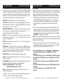
5-Pin XLR DMX Connectors. Some manufactures use 5-pin DMX-
512 data cables for DATA transmission in place of 3-pin. 5-pin DMX
fixtures may be implemented in a 3-pin DMX line. When inserting standard 5-pin data cables in to a 3-pin line a cable adaptor must be used,
these adaptors are readily available at most electric stores. The chart
below details a proper cable conversion.
3-Pin XLR to 5-Pin XLR Conversion
Conductor
3-Pin XLR Female (Out)
5-Pin XLR Male (In)
Ground/Shield
Pin 1
Pin 1
Data Compliment (- signal)
Pin 2
Pin 2
Data True (+ signal)
Pin 3
Pin 3
Not Used
Do Not Use
Not Used
Do Not Use
ADJ Products, LLC - www.adj.com - FLAT PAR TRI18XS User Manual Page 6