1
original shipping materials are approved for both air and ground shipment. Make sure that the shipping
container(s) contains the following:
1. Heavy Transportation Module
2. Accessory Box
a) Fan Shroud Assembly (12V or 24V)
b) Accessory Kit (including junction box)
3. User Manual
If the unit is found to be defective or any parts are missing, contact the factory. A Return Material
Authorization (RMA) number must be issued prior to returning the unit for repair or replacement.
3.
Installation
3.1. Mechanical
The heavy transportation modules can be mounted in multiple orientations and requires the proper
hardware to be used. Good, high voltage electrical practices should be observed in design of the module
installation. The supported orientations are:
Horizontal, straight.
Vertical, on the longer side. For this orientation, the module needs to be bolted to a supporting
wall or structure.
Any angle between horizontal, straight and vertical, on the longer side. The module must be
properly bolted to a supporting structure and the top of the module must face upward.
The mounting surfaces on the bottom angles are designed to support the module with no additional
mechanical contact. Fasteners must be Class 12.9 or stronger, must be torqued properly, and must
include flat washers and locking devices. The following fasteners (not supplied) are recommended for
attaching the modules to the vehicle: 4 screws, M8 -1.25 x 20 mm long. Please note that longer screws
may be required if using through-holes and nuts.
Note: Maxwell Technologies specifications and warranty apply only when mounting the module using
the feet as assembled at the factory. Removal of the feet and mounting directly to the body of the
module voids the warranty. Should the module be mounted without the factory supplied feet (mounting
points are detailed in document 1014553, available by download at http://www.maxwell.com), the user is
required to provide shock and vibration test data to re-validate the warranty.
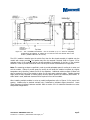
Refer to Figures 3.1, below for overall module dimensions, mounting envelope, and mounting hole
locations. The use of alternate module mounting orientations or custom feet other than those provided
by Maxwell Technologies will result in voiding the warranty unless such uses have been disclosed to
Maxwell and approved by Maxwell by express written consent prior to implementation. Zones 1 (inlet)
and 2 (exhaust) are reserved for cooling air. One of the sides A, B, or C must be completely unobstructed and adjacent to ambient air on both the inlet and exhaust sides of the module.
User Manual – BMOD0063 version 2.2
Document no.: 1014343.5 © 2008 Maxwell Technologies, Inc.
Page
®
2