1
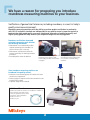
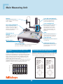
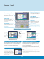
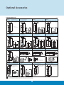
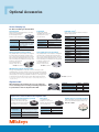
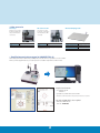
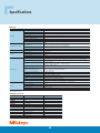
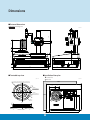
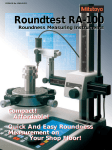
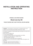
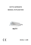
Form Measurement Compact Roundness Measurement ROUNDTEST RA-10 Catalog No. E15019 Compact new roundness tester combines outstanding cost/performance ratio with full measurement capabilities We have a reason for proposing you introduce roundness measuring machines to your business. Verification of geometrical tolerances, including roundness, is a must in today's quality-conscious environment. Roundness measuring machines with the ability to perform product verification in conformity with ISO, JIS and other standards are indispensable to any quality control system that aspires to implementing high-grade quality assurance. Heightened awareness of production quality and higher quality goods will help enhance your corporate image with the buying public. Roundness verification attempted using basic measuring tools involves the following drawbacks: • Measurement is not conducted by a radius method conforming to the standards, for which a reference axis is necessary. • Measurement verification that meets the accuracy required by the drawings cannot be performed. • Recorded profiles cannot be obtained. Diameter measurement using a micrometer cannot detect an oddnumber lobing condition and resolution is marginal. Once roundness measuring machines are introduced into quality control: •Reduction of nonconforming parts will translate into lower overall cost of manufacture. •Product quality will improve and the time-to-market for new product will be reduced. •Corporate image will be enhanced. Definition of Roundness f Roundness of a profile or contour (C) is the difference in radius (f) of two concentric circles that enclose C when the separation of these circles C is a minimum, and is indicated as ‘roundness xx mm’ or Rmin ‘roundness xx μm’. Rm ax 2 Three-point method using an indicator and V-block has better resolution but is not sensitive to common lobing conditions. High-Precision Roundness Measurement Simple, beginner-friendly operation • The key layout is large and simple so is easy to view and easy to understand. • One-shot setup recall function: Complex setups are stored in advance, ready for recall when required by one-key operation. • Zero-setting function: The detector’s level can be set to zero (0) with one single key press. This relieves the user from the chore of meticulously positioning the detector. • The operation handles for vertical direction (Z axis) and radial direction (X axis) adjustments have been positioned on the slider for best operability. • Because setups can only be altered in administrator mode, the machine operator can be prevented from inadvertently changing settings. High accuracy even though a low-end machine Despite being a low-priced model, the turntable with air bearings offers rotational accuracy as high as (0.04+6H/10000)μm, thus assuring a precision that compares well to that of high-end models. Large LCD panel displays measurement results and recorded profiles in an easy-to-view fashion The built-in high-grade thermal printer prints out measurement results and recorded profiles on demand Compact design means small installation space The machine calls for only a small installation space as its compact body integrates the measuring unit, electronics and printer. Options that further enhance usability Use of a part setting jig exactly fitting the object being measured eliminates the need for the centering and leveling adjustments which would otherwise be required prior to measurement. An X-axis stop in the radial direction allows the detector to be positioned easily according to the object to be measured, eliminating the task of fine positioning when measurement is repeated. * For details on the options, see pages 3 and 8. Four easy steps to measurement Clamp the workpiece to the jig. Bring the detector into contact with the workpiece. Press the [CONDITION (setup recall)] button, as needed. *If measurement is always conducted using the last setup, there is no need to recall this because the machine always starts up with the same settings that were effective immediately before the machine was powered down last time. *Combined use of the zero-setting function and X-axis stop (Optional) will result in securing even higher efficiency when identical workpieces are measured repetitively. 3 Press the [START] button. Main Measuring Unit Detector Z-axis ABS scale (Optional) Allows simple positioning of the workpiece due to its wide measuring range of ±1000μm. When the ABS scale is fitted, positioning in the Z-axis (vertical) direction is performed with higher accuracy. X-axis stop (Optional) Part setting jig (Optional) Allows fast positioning of the stylus after the workpiece is clamped so that measurement can be started immediately without the need for a delicate positioning operation. This greatly increases work efficiency on batch work. Can be selected to best suit the workpiece, which can be clamped/ released in a single action. High regripping accuracy eliminates the need for centering and leveling. Slider High-precision air bearings Carries the manual operation knobs positioned together for convenient Xand Z-axis stylus position adjustment. The highest accuracy in its class, (0.04+6H/10000)μm, has been achieved. Large LCD panel Clearly displays measurement results and recorded profiles. Built-in printer Prints measurement results. Simple operation panel Space-saving design The compact body integrating the measuring unit, electronics and printer poses no problem in installing the machine. Large-sized buttons allow easy recall of stored measurement setups and help prevent input errors. High-precision air bearings provide highly accurate measurement Measurement results can be sent to the built-in printer or exported for external processing and storage Turntable axis stability is the most critical specification of a roundness measuring machine since this axis provides the datum from which the stylus deflection is measured for every type of analysis. For this reason the RA-10 is equipped with specially designed air bearings that assure high rotational accuracy to guarantee high-precision measurements. As these bearings are inherently non-contacting they are free of any degradation arising from normal use, so the machine retains high accuracy even when used for an extended period of time. Measurement results and recorded profiles can be sent to the highgrade built-in thermal printer or exported via the SPC and RS-232C output functions or text file output function to USB memory. Sample print by built-in printer Rotational accuracy (µm) Graph of rotational accuracy versus height above table surface. 0.14 0.12 0.10 0.08 0.06 0.04 0.02 0.00 0 20 100 60 80 40 Measuring height (mm) 120 4 Control Panel Supports 16 languages Japanese, English, German, French, Italian, Spanish, Portuguese, Korean, Traditional Chinese, Simplified Chinese, Czech, Polish, Hungarian Turkish, Swedish, Dutch Measurement screen / Result screen switching Switches between measurement screen and analysis result screen at one touch of a button. Large LCD screen Displays measurement results and recorded profiles in an easy-tounderstand manner. Printer control While automatic print is available, setting can also be made to print desired results only, thus resulting in the saving of paper resources. Setup Recall Frequently used measurement setups can be stored in advance, ready to be called up by one touch of a button. Zero Set button Setup definition A potent tool for establishing optimum positioning of the detector. Measuring range switching Setup button Simplified communication program for ROUNDTEST RA-10 The Roundtest RA-10 has a USB interface, enabling data to be transferred to a spreadsheet or other software. Measuring posture Measuring height Comment input Tolerance Number of measured cross-sections (Max. 5) Notching conditions None Specified level Specified angle Displayed profiles Circular Developed Display magnification Filter Cutoff Calculation method Cutoff Filter Sample Measurement Screen Display magnification Calculation method Sample Result Screen (Roundness) Useful functions help setting up prior to measurement Limaçon function compensates for eccentricity When a high-resolution range measurement is needed, for which accurate positioning is required, the Zero Set button allows the detector to be set at the optimum position. The machine delivers the measurement results for a workpiece after automatically correcting for eccentricity and inclination. A displacement offset between the turntable axis and that of the part under measurement results in distortion of the measured form (limaçon error) and consequentially produces an error in the calculated roundness value. The larger the eccentricity, the larger is the error in calculated roundness. The RA-10 supports accurate measurement with a limaçon error correction function, which is provided to correct such errors arising from eccentricity. Measurement data editing function Any part of a profile that is not to be included in the calculation can be automatically excluded from the measurement data. Therefore notches in the profile can be ignored, or data produced by scratches can be deleted while observing recorded profiles on the screen. Notes: 1. The limaçon error correction is effective only when measuring a workpiece of larger diameter than that of the tip of the probe. 2. If the effect obtained with the limaçon error correction function is not sufficient, use the optional alignment table (to be purchased separately) to establish precise centering of the workpiece. 5 Types of Analysis with the RA-10 Feature Characteristic Characteristic Symbol Measurement Method Sample Result Screen Explanation Roundness Roundness (MZC) Roundness (MZC definition) of a profile is the difference in radius of two concentric circles that enclose the profile when the separation of these circles is a minimum. Form Flatness Flatness Flatness of a profile is the distance between two planes enclosing the profile when this distance is a minimum. Concentricity Concentricity Concentricity of a profile is twice the shortest distance between the center of the profile and the datum. Location Coaxiality Coaxiality Coaxiality of the axis of a profiled surface is twice the shortest radial distance between the axis and the datum at the measured positions. Circular runout Circular runout (radial) Runout Circular runout (radial) of a profile is the radial distance between two circles enclosing the profile and concentric with the datum when this distance is a minimum. 6 Optional Accessories Interchangeable Styli Useful for notched workpieces For standard applications For inside-corner applications ø4 5.5 66 ø4 Example 11.7 For extra small hole applications Dia.: ≥1mm, Depth: ≤2.5mm 30° 7.5 12AAL028 Stylus for small and deep holes (stylus tip: ø1.6 carbide ball, L=40) 12AAL030 Stylus for small and deep holes (stylus tip: ø1.6 carbide ball) 12AAL026 Stylus for small holes (stylus tip: ø0.8 carbide ball) Example 52.5 Example 7 12AAL029 Stylus for extra small holes (stylus tip: ø0.5 carbide ball) 12AAL024 Stylus for corners (stylus tip: R0.25 sapphire) For stepped applications ø4 66 In ID measurement Dia.: ≥7.5mm, Depth: ≤50mm 52.5 52.5 66 ø4 12AAL023 Stylus for grooves (stylus tip: R0.25 sapphire) 66 *Standard accessory (stylus tip: ø1.6 carbide ball) 52.5 12AAL021 Standard stylus Unit: mm 12AAL022 Stylus for notched workpieces (stylus tip: ø3 carbide ball) For small and deep hole applications Dia.: ≥3mm, Depth: ≤18mm For small hole applications Dia.: ≥1.5mm, Depth: ≤10mm For small and deep hole applications Dia.: ≥3mm, Depth: ≤38mm Enlarged image Enlarged image ø4.5 Enlarged image ø1.2 ø1.5 ø0.8 carbide ball ø3 ø1.6 carbide ball 12AAL027 12AAL032 Stylus for small holes (stylus tip: ø1 carbide ball) Cranked stylus (stylus tip: ø0.5 carbide ball) 12AAL033 Cranked stylus (stylus tip: ø1 carbide ball) ø3 ø1.6 carbide ball 12AAL034 Stylus for flat surface 68 67.5 67.5 For small hole applications ø1.2 20 10 18 ø1 ø0.5 carbide ball ø0.6 12 2.5 3 ø0.3 38 52.5 52.5 52.5 52.5 66 66 ø4 66 66 ø4 40 Enlarged image ø4 5 ø4 66 5.5 ø4 2.5 66 ø1 carbide ball 66 0.5 R1 ø4 ø2 ø0.5 carbide ball 52.5 66 ø4 For upper/lower surface in a narrow groove Example 22.7 8.2° Example Note: This stylus cannot be used for OD/ID measurement. ø1 carbide ball 12AAL031 Disk stylus 12AAL043 M2 tapped shank for CMM styli 5° ø2 ø12 M2 depth 5 R1 0.5 Machining marks ø4 0.5 10 R 15 ø4 56 Example For narrow groove applications 42.5 52.5 66 52.5 66 ø4 Example Compatible with CMM styli with M2 threaded shank Compatible with CMM styli with M2 threaded shank Filtering out the effects of asperities by tracing with R15 tipped stylus ø4 12AAL044 M2 tapped shank for CMM styli 66 68.5 12AAL025 Stylus for filtering asperities (machining marks) 52.5 ø0.8 *■ portion shows stylus except for the cranked stylus and stylus for flat surface. *( ) dimension shows a distance from the tip end of stylus or the center of tip ball to the connecting surface of detector. *Customized special interchangeable styli are available on request. Please contact any Mitutoyo office for more information. 7 M2 3.5 Optional Accessories Various Clamping Jigs For direct mounting on the turntable Centering chuck When measuring a small-sized workpiece, the chuck provides good operability and the knurled ring allows the workpiece to be clamped easily. Order No. 211-052 Part holding range O.D. (Internal jaws) 1– 36mm O.D. (External jaws) 25 – 79mm I.D. (Internal jaws) 16 – 69mm Centering error Within 150μm*1 Mass 2.5kg Collet chuck Individual collets*4 Provides high clamping repeatability due to the use of optional precision collets. (See table below.) Order No. Part holding range Centering error Mass These collets are acquired to match the workpiece diameter range required. 211-051 O.D. ø0.5 –10mm*2 Within 50μm*3 1.4kg *2: Optional collets to match the workpiece size range are required. *3: When measured with ø5mm pin gauge at measuring height of 30mm. *1: When measured with ø10mm pin gauge at measuring height of 30mm. V-block jig A [Semi-custom product] The cylindrical surface of the workpiece is held against the V-block and secured with the screw-type clamp. This is a semi-custom-made product (ø10 to ø100mm) that is shipped out after adjusting the position of the V-block according to the workpiece size. This jig allows workpieces of the same size to be measured without having to center each one. V-block jig B [Semi-custom product] The cylindrical surface of the workpiece is held against the V-block and secured with the screw-type clamp. This is a semi-custom-made product (ø10 to ø100mm) that is shipped out after adjusting the position of the V-block according to the workpiece size. This jig allows workpieces of the same size to be measured without having to center each one. 211-053: for ø50mm Order No. 12AAH402 12AAH403 12AAH404 12AAH405 12AAH406 12AAH407 12AAH408 12AAH409 12AAH410 12AAH411 12AAH412 12AAH413 12AAH414 Part Holding Range (O.D.) ø0.5 – 1.0mm ø1.0 – 1.5mm ø1.5 – 2.0mm ø2.0 – 2.5mm ø2.5 – 3.0mm ø3.0 – 3.5mm ø3.5 – 4.0mm ø4.0 – 5.0mm ø5.0 – 6.0mm ø6.0 – 7.0mm ø7.0 – 8.0mm ø8.0 – 9.0mm ø9.0 – 10.0mm *4: A collet cannot be mounted on the turntable without a collet chuck. 211-054: for ø50mm OD/ID mating jig [Semi-custom product] These jigs are specially made to locate plain sections of a workpiece so that loading/unloading is very quick. Workpiece centering is automatically provided by just one initial centering operation on the jig, when first installed, so measurement can be started as soon as the jig is loaded with a workpiece. No clamping is used so the workpiece must be heavy enough to remain stable during measurement. 211-055: for ø10mm *An OD/ID master mating part to match the workpiece diameter is required separately [(available to special order (max. ø30mm)]. Alignment table Order No. Centering adjustment range Leveling adjustment range Maximum loading Mass When installed on the turntable, this accessory enables the user to efficiently perform centering and leveling adjustments in synchronization with the adjustment Navi DAT. 12AAH425 ±3mm ±1° 3kg 7kg 12AAH426 ±3mm/.12” ±1° 3kg 7kg *With mechanical micrometer head type (12AAH427) is available. Options that can be installed on the alignment table Centering chuck (knurled ring operated) When measuring a small-diameter workpiece, the chuck provides good operability and the knurled ring allows the workpiece to be clamped easily. Order No. 211-032 O.D. with internal jaws ø1– ø36mm Holding range I.D. with internal jaws ø16 – ø69mm O.D. with internal jaws ø25 – ø79mm External size (D x H) ø118 × 41mm Mass 1.2kg Microchuck For clamping a small workpiece, 1 mm or less in diameter, that cannot be held in the centering chuck. Order No. Holding range External size (D x H) Mass 8 211-031 O.D.: ø0.1– ø1.5mm ø107 × 48.5mm 0.6kg Auxiliary stage for a low-height workpiece Used for measuring a workpiece whose diameter is 20mm or less and whose height is 20mm or less. Order No.: 356038 • Other accessories X-axis stop Allows the user to return the detector rapidly and easily to a fixed position on the X axis. Order No. Mass 12AAH320 65g SD scale for Z axis* Vibration damping stand Scale unit for accurate positioning of the slider in the Z-axis direction (ABS scale used). Order No. Mass 12AAH318 450g * Shipped out attached to the RA-10 machine, or will be installed on site by Mitutoyo service personnel. Order No. Vibration damping system External size Max. loading 211-013 Diaphragm type air spring 615 × 515 × 51mm 150kg • Simplified communication program for ROUNDTEST RA-10 The Roundtest RA-10 has a USB interface, enabling data to be transferred to a spreadsheet or other software. We also provide a program that lets you create inspection record tables using a Microsoft Excel* macro. Required environment: • OS: Windows XP-SP3 Windows 7 • Spreadsheet software: Microsoft Excel 2010 *Windows OS and Microsoft Excel are products of Microsoft Corporation. The optional USB cable is also required. • USB cable for RA-10 series Order No.12AAH490 9 Specifications Main unit Model Turntable Bearing type Rotational accuracy (radial) Rotational accuracy (axial) Rotation speed Effective table diameter Maximum turntable loading Maximum probing diameter Maximum workpiece diameter Vertical travel Vertical column (Z axis)) Horizontal arm (X axis) Detector Maximum probing height Maximum probing depth Horizontal travel Measuring force Standard stylus (12AAL021) Measuring range Measuring direction Measuring range Magnification Filter type Cutoff value Electronic unit Number of measuring sections Reference circle for evaluation Evaluation capability Data output Display Printer Display languages Others Power supply Power consumption Air pressure Air consumption Mass RA-10 Air bearing (0.04+6H/10000)µm H: Probing height (mm) JISB7451-1997 (0.04+6X/10000)µm X: Probing radius (mm) 6rpm ø150mm 10kg ø100mm ø320mm 117mm ·Buttom position: Approx 35mm from the turntable top*2 ·Top position: Approx. 152mm*1 from the turntable top*2 152mm from the turntable top 100mm (minimum ID: ø30mm) using the standard stylus –25mm to 50mm 100mN (±30%) Stylus tip: ø1.6mm carbide ball (Refer to page 7 for detailed information.) ±1000µm Two directional (IN/OUT switchable) ±1000µm, ±100µm, ±10µm ×5, ×10, ×20, ×50, ×100, ×200, ×500, ×1,000, ×2,000, ×5,000, ×10,000, ×20,000, ×50,000, ×100,000, ×200,000 Phase corrected: 2CRPC75, 2CRPC50 Not phase corrected: 2CR75, 2CR50 Gaussion, filter OFF 15upr, 50upr, 150upr, 500upr 15-150upr, 15-500upr, 50-500upr 1-section to 5-section: Roundness, Coaxiality, Flatness 1-section to 3-section: Circular runout (radial) 2-section: Concentricity LSCI, MZCI, MICI, MCCI Roundness, Coaxiality, Concentricity, Flatness, Circular runout (radial) RS-232C I/F, SPC, USB stick memory LCD 117.2 × 88.4mm Thermal line printer, optional external printer Japanese, English, German, French, Italian, Spanish, Portuguese, Korean, Traditional Chinese, Simplified Chinese, Czech, Polish, Hungarian Turkish, Swedish, Dutch AC100 to 240V, 50/60Hz 32– 36W 0.39MPa 30L/min (minimum) 26kg *1: Top position will vary depending on any attachments installed. *2: No attachments installed. Standard accessories Order No. 350366 611755-04 11BAB941 12AAL021 12BAJ340 — — — — — — — — Name Magnification adjusting film Gauge block (35mm, JIS Grade 2) Level Standard stylus Printer paper* Receptacle Hose band Power cable Leveling spanner Philips screwdriver Key wrench 0.9, 2 and 4 Machine cover User's manual Quantity 2 pcs. 1 pc. 1 pc. 1 pc. 2 rolls 1 pc. 1 pc. 1 pc. 1 pc. 1 pc. 1 pc. (0.9), 2 pcs. (2), 1 pc. (4) 1 pc. 1 copy *12AAH181: Optional printer paper set (10 rolls) 10 Dimensions n External dimensions : Measuring area 117 323 Unit: mm 50 20 143 181 35 25 25 400 135 25 75 115 360 450 n Turntable top view n Installation floor plan Unit: mm t: Power inlet t: Air inlet Four concentric grooves: W1xD0.5 (ø32, ø60, ø88, ø116) Unit: mm PCD 124 100 min.100 Wall 65 3-M5xD10 (120° arrangement) 3-M5xD10 (120° arrangement) Wall 80 360 PCD M5xD10 C3 ø140 min.60 11 max. 505.5 Coordinate Measuring Machines Vision Measuring Systems Form Measurement Optical Measuring Sensor Systems Test Equipment and Seismometers Digital Scale and DRO Systems Small Tool Instruments and Data Management Specifications are subject to change without notice. Note: All information regarding our products, and in particular the illustrations, drawings, dimensional and performance data contained in this pamphlet, as well as other technical data are to be regarded as approximate average values. We therefore reserve the right to make changes to the corresponding designs, dimensions and weights. The stated standards, similar technical regulations, descriptions and illustrations of the products were valid at the time of printing. Only quotations submitted by ourselves may be regarded as definitive. 226 1312 1 Ab (CH) HS, Printed in Japan Export permission by the Japanese government may be required for exporting our products according to the Foreign Exchange and Foreign Trade Law. Please consult our sales office near you before you export our products or you offer technical information to a nonresident.