1
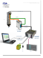
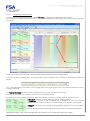
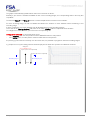
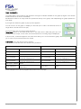
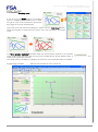
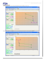
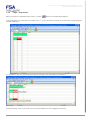
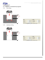
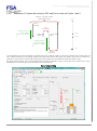
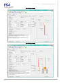
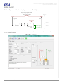
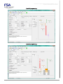
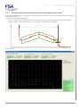
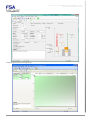
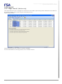
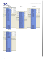
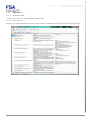
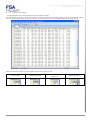
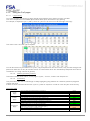
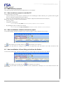
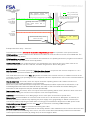
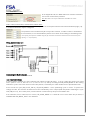
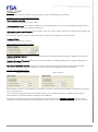
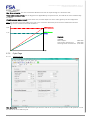
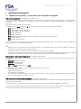
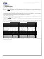
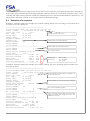
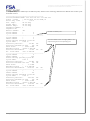
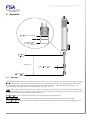
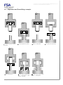
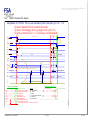
This document is the property of FABRICOM SYSTEMES D'ASSEMBLAGE and may not
be reproduced or disclosed without their authorisation
MULTIPLE INDEX AREA:
In the "Appendix" tab, the "Multi Index" box must be checked to
use the four "index offset" positions.
Note: Multi Index can only be enabled if the "Field Bus" box is also
checked.
Index1 offset, Index2 offset, Index3 offset, Index4 offset:
Press opening offset* of a distance of N exact multiples of the screw pitch between this index and index0 (origin). Up
to 4 indexes maximum may be configured.
The positions of the N offsets may be in any order. However, to make it easier to understand
the movements, it is recommended to place them in either an increasing or decreasing order.
*The opening of the press is available using the (E) command. The maximum offsets must be less than the press
opening - 2 + P (screw pitch).
Wiring the Multi-Index unit
Connecting the Multi-Index unit:
See section 6.2 of the MVATNet manual
Use of multiple indexes:
In home position (Index0), the PLC changes from index0 to index-N (from 1 to 4) by coding the value N into word
OUT1 (OUT1.7=C.2^2, OUT1.6=C.2^1, OUT1.5=C.2^0) and by checking that FB_XCHG_INDEX=0 after having
started the cycle to move the device to this index position, checked by the value declared in the Specifications tab.
At the end of the cycle (FB_CYCLE_ON=0), FB_XCHG_INDEX=1 if the positioning cycle is correct. To protect the
change of index, the selection of Index-N must be controlled by a PLC output (PNP 24V) before releasing the cycle
start (FB_DCY=0), the re-read (echo) of this selection is carried out by an input of the MVAT rack.
If the selection echo or index-N is not correct, FB_XCHG_INDEX=0. If index-N is not correct when the pin starts, a
standard fault FBV_BRCH_HAUT=0 is obtained.
Rhapsodie.net – User Guide
2013-09
74/130