1
Rhapsodie.Net
Electronic
User Guide
January 2014 Version
Rhapsodie Version: From 1.6.0.00
Rhapsodie.net – Guide l'Utilisateur
09-2013
1/130
This document is the property of FABRICOM SYSTEMES D'ASSEMBLAGE and may not
be reproduced or disclosed without their authorisation
MVAT ® is a registered trademark of FABRICOM Systèmes d'Assemblage.
The other trademarks referred to belong to their respective owners.
Warning:
FABRICOM Systèmes d'Assemblage S.A. reserves the right to change without warning all or part of the technical application of the
information contained in the present document. This information must not be interpreted as a commitment on the part of
FABRICOM Systèmes d'Assemblage.
FABRICOM Systèmes d'Assemblage S.A. declines all responsibility for the use of this information or the equipment described in the
present document. The disclosure of this information, on any grounds whatsoever, may in no way act as a licence and does not
assume the protections and rights attached to the use of the information described in this document. The reproduction, reference
and use of all or part of this document in violation of the provisions of the intellectual property code are subject to prior written
authorisation from:
Fabricom Systèmes d'Assemblage Headquarters
10, rue La Fayette - BP 1565, Z.A.C. La Fayette, F-25009 Besançon Cedex 3
Tel.: +33 (0)3 81 26 71 71, Fax: +33 (0)3 81 26 72 72
Rhapsodie.net – User Guide
2013-09
2/130
This document is the property of FABRICOM SYSTEMES D'ASSEMBLAGE and may not
be reproduced or disclosed without their authorisation
CONTENTS
1
Servo-controlled electric press-fitting ........................................................................5
1.1
1.2
1.3
1.4
Geometric identification
Sequence, Cycle, Curve: definitions
Cycles, chains
Quality check
1.4.1 Cycle OK
1.4.2 Curve check OK
1.4.3 Sequence OK.
5
6
6
7
7
7
8
2
Hardware ...................................................................................................................9
3
Installation ................................................................................................................10
4
Updating software ...................................................................................................15
4.1 Uninstallation
4.2 Re-installation
5
15
15
1st Run ......................................................................................................................16
5.1 Software registration
5.2 Organisation of the software
5.3 Creating a project with 1 station and 1 press-fitting unit
5.3.1 Creating a Project, Station and File path
5.3.2 Creating a Press-fitting Unit
5.4 Programming
5.4.1 Specifications
5.4.1.1 Description of fields
5.4.2 Cycles
5.4.2.1 Description of fields
5.4.3 Profiles
5.4.3.1 Configuring recording ranges
5.4.3.2 Using a envelope Curve to place the Recording Ranges (Storing Windows)
5.4.3.3 Configuring check windows
5.4.4 Page: "Sequences"
5.5 Examples of conventional programs
5.5.1 Press-fitting
5.5.2 Interference fitting
5.5.3 Sequence of 3 cycles with return by PLC and Curve check on Cycles 1 and 3
5.5.4 Sequence with a "Looping" phase then a "Check" phase
5.5.5 Sequence with single press-fitting with a narrowly-targeted curve check
5.5.6 Page: "Results": (field bus only)
5.5.7 Help Menu
5.5.7.1 Rhapsodie Guide
5.5.7.2 MVAT fault List
5.5.7.3 "UE references page"
5.5.7.4 Page: "About..."
6
16
17
18
18
21
24
24
25
26
26
29
32
34
35
40
41
41
41
42
48
51
57
59
59
59
60
61
Advanced usage ......................................................................................................62
6.1 Using Rhapsodie.Net: General principles
6.1.1 Project Storage directories
6.1.2 Opening a project directly
6.1.3 Upload/Import/Export
6.1.3.1 Upload (Retrieval of programs from MVAT)
6.1.3.2 Import
6.1.3.3 Export
6.1.4 Sending programs
6.1.4.1 Case of communicating through an UExp-MVAT panel
Rhapsodie.net – User Guide
2013-09
62
62
63
63
63
63
63
64
64
3/130
This document is the property of FABRICOM SYSTEMES D'ASSEMBLAGE and may not
be reproduced or disclosed without their authorisation
6.1.5 Using the "List" pages
6.1.5.1 Copy/Pasting
6.1.5.2 Initialize (previously “Delete”)
6.1.5.3 Consistency
6.2 How to backup projects
6.3 How to retrieve a project on another PC
6.4 How to add/delete a Station to/from the project
6.5 How to add/delete a Press-fitting unit to/from the Station
6.6 Results
6.7 Advanced functions
6.7.1 Specifications page
6.7.1.1 "Appendix" tab
6.7.1.2 "Maintenance" tab
6.7.2 Cycle Page
6.7.2.1 "Advanced" tab
6.7.2.1 "Page" tab - Force Check Cycle type
6.8 Calibration and learning cycle in pressing mode
6.8.1.1 Definition
6.8.1.2 Description
6.9 Calibration and learning cycle in pulling mode
6.9.1.1 Definition
6.9.1.2 Description
6.10 Using a UEXP-MVAT and the communication tools
7
Additional information ..............................................................................................84
7.1 Number of sequences, cycles and curve acquisition programs
7.2 Operating modes
7.2.1 Mode with PLC
7.2.2 Mode without PLC
7.2.3 Forced manual mode
7.3 Quality results
7.4 Page: "Curves"
7.5 Access level
7.6 TRACEABILITY OF SETTINGS
8
84
85
85
85
86
86
87
97
98
Execution Journal ....................................................................................................99
8.1 Execution of a calibration on the lower gage
8.2 Execution of a calibration on the upper gage
8.3 Execution of a sequence
9
65
65
65
65
66
66
66
66
67
67
67
67
72
76
76
79
80
80
80
81
81
81
82
99
99
100
Appendix ................................................................................................................102
9.1
9.2
9.3
9.4
9.5
9.6
9.7
9.8
Glossary
Position and speed diagram
Acquisition and Press-fitting: example:
Meaning of indicators on front panel
Analysis of malfunctions when first switched on
List of execution faults
Liste des défauts liés au contrôle courbe de type Profil
Appendix 7 - Principle diagrams
9.8.1 Principle diagram
9.8.2 ON/OFF I/O with PLC diagram
9.8.3 ON/OFF I/O without PLC diagram
9.9 Appendix 8 - Communication report
9.10 Appendix 9 – MVAT Com
9.11 Appendix 10 – GRADIENT FUNCTION
9.12 Appendix 11 - Rhapsodie.net Version
Rhapsodie.net – User Guide
2013-09
102
103
104
105
109
110
117
119
119
120
121
122
124
125
130
4/130
This document is the property of FABRICOM SYSTEMES D'ASSEMBLAGE and may not
be reproduced or disclosed without their authorisation
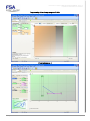
1 Servo-controlled electric press-fitting
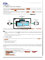
A servo-controlled electric press-fitting unit (UE) consists of:
- an instrumented (for force measurement) motor-driven shaft (the "pin")
- a power amplifier (the "servo")
- an electronic control unit (MVAT) (the "MVAT card")
The electronic control unit controls the movement of the pin shaft whilst monitoring the force being exercised on the
shaft. It is controlled by On/Off inputs or by a field network (Profibus, Ethernet, Profinet for example). It can
communicate with the outside world through 2 serial links (1 RS485 and 1 RS232).
The "programming" of a press-fitting unit involves defining position and force settings.
The interface with the press-fitting unit is carried out by the program Rhapsodie.net.
1.1
Geometric identification
IMPORTANT: The following is a full description of FSA's design approach
The positions of the end of the pin shaft are identified on an axis.
The zero point is defined during the calibration and learning cycle in pin pressing mode.
Positions decrease when the shaft exits and increase when it returns. It is essential to calibrate the press-fitting unit
before using it otherwise it will not be possible to carry out a sequence.
Note: this calibration operation is requested by the electronic control unit each time the electrical environment of the
press-fitting unit is changed and must be repeated every time a change is made to the mechanical environment of the
press-fitting unit.
The electronic control unit knows the position of the pin shaft through the pulses delivered by the speed controller (the
speed controller drives the motor through the synchro-resolver mounted on the shaft).
An inductive sensor (called the Index) active when the shaft is in home position, allows the absolute number of motor
revolutions to be determined.
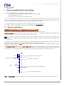
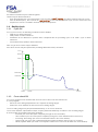
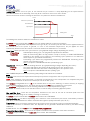
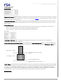
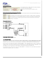
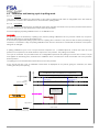
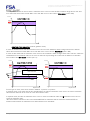
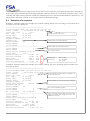
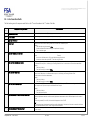
The Top Dead Centre (TDC) and the lower safety point delimit the working area of the press-fitting unit. Top dead
centre equates to the position reached at the instant of the pulse on the first revolution after the loss of the index when
the shaft exits. The lower safety point is a setting defined according to the mechanical environment of the pin
Top -1
Presence of index
Top 0
Top
no...
Idle position, Home, Origin (or)
Top Dead Centre (TDC)
Position 0 (defined during calibration)
Lower safety point (setting)
Note: In "manual raise" mode, the pin stops on the index while during normal operation, it stops in the idle position.
Rhapsodie.net – User Guide
2013-09
5/130
This document is the property of FABRICOM SYSTEMES D'ASSEMBLAGE and may not
be reproduced or disclosed without their authorisation
1.2
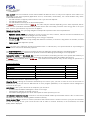
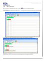
Sequence, Cycle, Curve: definitions
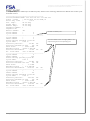
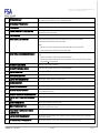
The programs (each, a series of pin shaft displacements) are called "Sequences". Each sequence is identified by a
number (1 to 512) and always starts with the shaft in idle position.
The sequences are made up of "Cycles" which can be chained together one after the other and are identified by a
number (1 to 384).
The change in the force during the sequence can be memorised in the "Curves" or in the "Profils". The curves or profils
constitute storage programs which are identified by a number (1 to 16 for the curves or 17 to 100 for the profils) and
allocated to a sequence.
ALL the settings describing sequences, cycles and curves are defined through the Rhapsodie.net GUI.
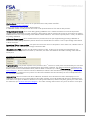
Sequence selection
by PLC (On/Off or
Fieldbus)
MVAT
Motor
movements
Measurement
recording
Sequence
Cycles
Curve
A sequence is therefore described very simply by the number of the first cycle to be executed and the curve number to
be used to save the force values measured during the movements of the pin.
Note:
- sequences, cycles and curves numbered "0" do not exist and are used to designate a non-existent element (for
example, the association of the curve "0" with a sequence, means "No storage program associated with this
sequence".
- The "Cycle start" input must be active throughout the execution of the sequence, otherwise the press-fitting units
stops immediately and signals an emergency stop.
1.3
Cycles, chains
A cycle describes an elementary movement of the pin. The main settings used to define a cycle are the trip force and
the trip position.
The MVAT card stops the pin shaft either:
- when the trip position is reached
- when the trip force is applied.
The system then simultaneously saves the final force and the position reached. Various types of configurable quality
checks enable the cycle to be declared OK or not OK. If the pin stops on the position, the force may go outside the
tolerances. Likewise, if it is the force which causes the trip, the position may not comply with the programmed
tolerances.
The following data is entered to describe the basic movement:
- the cycle type, chosen from the options "Press-fit", "Acquisition" or "Positioning"
- the direction of movement: "Pressing" or "Pulling"
- the Engagement position, which defines the change from the Approach speed to the Working speed.
- the Slowing down position, which defines the change from the Working speed to the Trip speed.
- the Trip position, and its tolerances
- the Trip force, and its tolerances
- the maximum allowed current
- the cycle to be chained if necessary
Rhapsodie.net – User Guide
2013-09
6/130
This document is the property of FABRICOM SYSTEMES D'ASSEMBLAGE and may not
be reproduced or disclosed without their authorisation
Pin shaft movements may be chained together.
Chains may be determined either:
- when programming the cycles themselves. This is known as SOFT chaining. The MVAT card will chain the cycles.
- from the outside (PLC), this is known as Hard chaining. At the end of the current cycle, the PLC selects the next
sequence to execute. The MVAT card then chains the sequences.
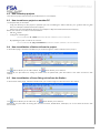
1.4
1.4.1
Quality check
Cycle OK
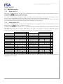
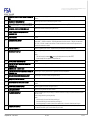
For a cycle to be OK, the following conditions must be fulfilled:
- Final force is within tolerances
- Final position is within tolerances
- Calculation of the difference in position when compared with the preceding cycle or an "initial " cycle is within
tolerances
- "Force Before Stop" (FBS) is within tolerances.
Note: any of these checks may be inhibited.
All of these checks may be represented (excluding differential check) as follows:
Force
Fmax
Fmin
FADmax
FADmin
Xmin
1.4.2
Xmax
Position
Curve check OK
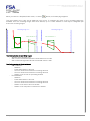
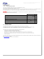
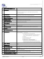
For a curve program to be declared OK, all the checks it carries out must also be OK.
A curve program:
- Stores the force during displacement for 5 separate recording ranges.
- Positions 5 check windows in total over these recording ranges.
The 5 recording ranges may be positioned absolutely, or on a force threshold.
The 5 check windows, trapezoidal in shape, may be positioned absolutely or relative to the recording ranges.
9 check modes are possible using these windows:
- Inclusion (the curve must pass completely through the check window)
- Strict inclusion (the curve must pass completely through the check window and not exit from it)
- Increasing, decreasing (the curve increases/decreases in the check window)
- Peak, trough (the curve has a maximum/minimum greater than/less than the entry or exit point)
- Mean, Dynamic Mean (the mean or the dynamic mean of the curve must be within the check window)
Rhapsodie.net – User Guide
2013-09
7/130
This document is the property of FABRICOM SYSTEMES D'ASSEMBLAGE and may not
be reproduced or disclosed without their authorisation
- Working (the working calculation - surface of the curve - must be between a maximum and a minimum)
Each check window has its own check.
It is of course possible to inhibit the quality of this check.
1.4.3
Sequence OK.
For a sequence to be OK, all the cycles executed and the curve must be declared OK by the MVAT.
Rhapsodie.net – User Guide
2013-09
8/130
This document is the property of FABRICOM SYSTEMES D'ASSEMBLAGE and may not
be reproduced or disclosed without their authorisation
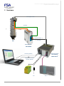
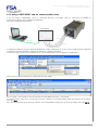
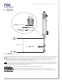
2 Hardware
Force signal + Index
Resolver
Power
Emulation Position
Command
PIN
Power Amplifier:
INFRANOR
FSA servo control
ELECTRONICS:
Monitoring (RS232)
MVAT Rack
®
Configuration and curve
reception (RS485)
24V
Rhapsodie.net – User Guide
2013-09
PLC
9/130
This document is the property of FABRICOM SYSTEMES D'ASSEMBLAGE and may not
be reproduced or disclosed without their authorisation
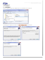
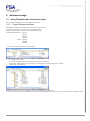
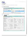
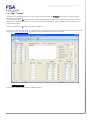
3 Installation
Insert the Installation medium (CD, USB flash drive, etc.) and double click on "Setup.exe"
The following screen appears, click "Next" then leave "C:\Rhapsodie.Net", and click "Next"
Click "Next", Rhapsodie.Net is now ready to start.
Rhapsodie.net – User Guide
2013-09
10/130
This document is the property of FABRICOM SYSTEMES D'ASSEMBLAGE and may not
be reproduced or disclosed without their authorisation
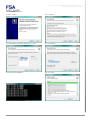
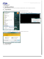
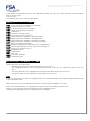
During installation, 2 extra softwares are installed :
- puTTY : terminal which able to dialog the MVAT card thrugh its Com1 port (RS232). It replaces the windows
Hyperterminal, not enable anymore since Windows 7.
- com0com : Generation and redirection of Virtual com port to Ethernet software (used only when an UExp-MVAT
panel is present on the station)
Steps : Installing puTTY
Choose « Next »
Leave the default directory
Choose « Next »
Clic on « Install »
Leave just the last checkbox checked and choose « Next » Clic on « Finish »
Rhapsodie.net – User Guide
2013-09
11/130
This document is the property of FABRICOM SYSTEMES D'ASSEMBLAGE and may not
be reproduced or disclosed without their authorisation
Steps : Install com0com
Choose « Next »
Clic « I Agree »
Uncheck all the checkbox and choose « Next »
Clic on « Install »
Screen during installation
Clic on « Next »
Rhapsodie.net – User Guide
2013-09
12/130
This document is the property of FABRICOM SYSTEMES D'ASSEMBLAGE and may not
be reproduced or disclosed without their authorisation
Clic on « Finish »
Now, all the softwares are installed, and an icon is added to the desktop:
Rhapsodie.net – User Guide
2013-09
13/130
This document is the property of FABRICOM SYSTEMES D'ASSEMBLAGE and may not
be reproduced or disclosed without their authorisation
And the following shortcuts are added in "Start"/"All programs" menu :
Notes: If Microsoft Framework 3.5
(Microsoft Windows components library)
is not present on the PC, it will be installed
automatically: (accept)
Rhapsodie.net – User Guide
If during installation a window mentions
Unknown Editor, accept:
2013-09
14/130
This document is the property of FABRICOM SYSTEMES D'ASSEMBLAGE and may not
be reproduced or disclosed without their authorisation
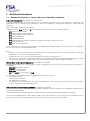
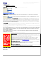
4 Updating software
To update Rhapsodie.Net, you must first uninstall the installed version, then re-install the new version.
4.1
Uninstallation
You just have to clic on the uninstall shortcut in « Start Menu/FSA Electric Press » :
Then follow instructions : answer “YES”
If during the uninstallation, a window alerts about unknow Editor, please accept :
4.2
Re-installation
See Installation chapter.
Rhapsodie.net – User Guide
2013-09
15/130
This document is the property of FABRICOM SYSTEMES D'ASSEMBLAGE and may not
be reproduced or disclosed without their authorisation
5 1st Run
5.1
Software registration
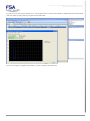
Run Rhapsodie.Net using the icon. When the software runs for the first time two information boxes are displayed as
the licence has not been entered. Confirm each by clicking on OK.
The Splash Screen is displayed for 5 sec., followed by the main window:
Rhapsodie.net – User Guide
2013-09
16/130
This document is the property of FABRICOM SYSTEMES D'ASSEMBLAGE and may not
be reproduced or disclosed without their authorisation
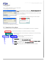
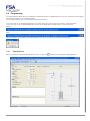
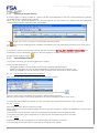
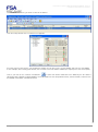
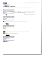
Then, to register Rhapsodie.net, select "Help"/"About"
The following data entry box appears:
Read off the Identification number and call Fabricom Presses after-sales
service (+33 (0)4-75-85-27-27) who will give you the registration key.
Remark : the updating from a version older than V1.5.0.7 to a new version
generate a new license ID.
After entering the key:
the following window appears showing the version installed.
You can now close Rhapsodie, then restart it.
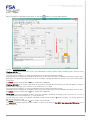
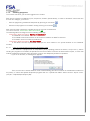
5.2
Organisation of the software
To provide a better idea of how Rhapsodie.net operates, the following diagram shows how it is organised:
PROJECT
Represents an assembly line or a production workshop for example
STATIONS
UNITS
Represents each station of an assembly line comprising one or more press-fitting
units for example
UNITS
Represents each of the press-fitting units on a
station for example
Specifications: general data representing the whole unit
Cycles: cycle settings (384 programmable cycles)
Profiles: "curve" settings, from now on called "PROFILES" (84 program profiles)
Sequences: sequence settings (512 programmable cycles)
Results: result settings which can be used by the PLC via the Field Bus
Rhapsodie.net – User Guide
2013-09
17/130
This document is the property of FABRICOM SYSTEMES D'ASSEMBLAGE and may not
be reproduced or disclosed without their authorisation
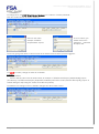
5.3
5.3.1
Creating a project with 1 station and 1 press-fitting unit
Creating a Project, Station and File path
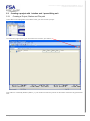
To be able to send programs to the MVAT card, you must create a project.
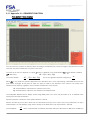
The "Stations" page opens: (you can make it full screen if you want to)
One station is created by default ("Station_1"), but neither the directory where the file will be saved nor any passwords
exist.
Rhapsodie.net – User Guide
2013-09
18/130
This document is the property of FABRICOM SYSTEMES D'ASSEMBLAGE and may not
be reproduced or disclosed without their authorisation
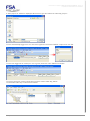
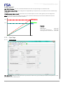
To change these, the FIRST thing that must be done is to create the "Creator" password:
Click the "Creator" button for station "Station_1".
Select a user name:
example: "EXPERT"
and password: "expert"
Then to confirm, you
double click on the
password confirmed
and press OK.
The red "4" goes green and the column in front of the station name shows the person logged in:
You NOW (not later!) change the name of the Station:
Example:
- "MY_STATION"
- then the directory where the file will be saved, for example "C:\FSA\Presses\Projets_Rhapsodie\My_Project"
(The directory C:\FSA\Presses\Projets_Rhapsodie\ will already have been created, and the directory "My_Project" is
created during this step using the "Create a new directory" button)
The diskette icon changes colour to indicate changes have been made. Click it.
Rhapsodie.net – User Guide
2013-09
19/130
This document is the property of FABRICOM SYSTEMES D'ASSEMBLAGE and may not
be reproduced or disclosed without their authorisation
A "Save project as" window is displayed. We decide to give the PJR file the name "My_Project":
You are automatically logged out. You must then log back in and enter "EXPERT" "expert" then click OK:
You are then logged in as creator (the "4" is in green) under the name "EXPERT" as before.
The project has been created, saved and includes a station called "My_Station".
The associated directory is structured as follows:
Rhapsodie.net – User Guide
2013-09
20/130
This document is the property of FABRICOM SYSTEMES D'ASSEMBLAGE and may not
be reproduced or disclosed without their authorisation
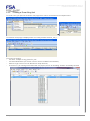
5.3.2
Creating a Press-fitting Unit
To create a unit, just open the "Insertion Unit" page which can be accessed from the setpoint menu:
or
The Insertion Units page is displayed with one unit by default: Insertion_Unit_1.
You must now change:
- the name: example "O-ring_Press-Fit_Unit"
- the Rack identification (see section "How to retrieve the MVAT rack identifier")
- Select the type of Pin in the "UE References" drop-down list,
- The boxes "C" (for running VisuCourbes with the project) and "P" for activating "Profiles" are already checked.
Rhapsodie.net – User Guide
2013-09
21/130
This document is the property of FABRICOM SYSTEMES D'ASSEMBLAGE and may not
be reproduced or disclosed without their authorisation
Then select the right COM port (see section "Managing COM ports")
And check the COM port selected is working properly by pressing the "Test" button which appears.
The response must be:
And not:
Or
Rhapsodie.net – User Guide
2013-09
22/130
This document is the property of FABRICOM SYSTEMES D'ASSEMBLAGE and may not
be reproduced or disclosed without their authorisation
You can save by clicking the diskette icon. The program which communicates between Rhapsodie.Net and the MVAT
card now starts up along with the program VisuCourbes.Net:
You are now ready to program specifications, Cycles, Profiles and Sequences.
Rhapsodie.net – User Guide
2013-09
23/130
This document is the property of FABRICOM SYSTEMES D'ASSEMBLAGE and may not
be reproduced or disclosed without their authorisation
5.4
Programming
The following description does not include the advanced features of Rhapsodie.Net. The less commonly used settings
are brought together in the "Advanced" tabs.
For more information, refer to the Advanced Functions section.
To access each of the programming pages, you must select the Unit for which you want to create programs.
To do this, click on the corresponding row. The title of the application changes when a unit is selected:
Before:
After:
If this is not done, the following message appears if you try to open one of the programming pages:
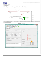
5.4.1
Specifications
When you select the Setpoint/Specifications menu, or click the
Rhapsodie.net – User Guide
2013-09
button, the Specifications page appears:
24/130
This document is the property of FABRICOM SYSTEMES D'ASSEMBLAGE and may not
be reproduced or disclosed without their authorisation
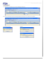
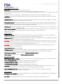
5.4.1.1
Description of fields
Pressing calibration force This is the force to be applied during the pressing calibration cycles. No force may be
programmed in a cycle which exceeds this force.
By Default, the value pre-entered is equal to 95% of the maximum force of the pin (e.g. we have chosen a UG30kN, i.e.
3000 daN maximum force, so the default value will be 2850 daN).
The minimum force which can be programmed is 25% of the maximum force (750 daN in our example)
The maximum programmable force is 100% - Offset default threshold = 5% by default, i.e. 95%.
For more information on the calibration cycle, see the sections on Calibration.
Safety force: This is the maximum allowed force during the approach phase of a cycle. If this force is encountered
during this phase, the MVAT card stops the shaft and outputs fault no. 8.
This is also the maximum value used for monitoring during movements in manual mode.
By Default, the value pre-entered is equal to 10% of the maximum force of the pin.
The minimum force which can be programmed is 1% of the maximum force.
The maximum force which can be programmed is 25 % of the maximum force.
Note: during a manual descent, the safety force is equal to the Safety force setpoint
If this setpoint is not entered, the safety force is set to 10% of the nominal value for the pin
Upper Gage: This is the AGGREGATED height of the upper gage and lower gage used during pressing calibration
cycles.
By Default, the value pre-entered is equal to 60mm.
Lower Gage: This is the height of the lower gage used during pressing calibration cycles.
By Default, the value pre-entered is equal to 0mm.
There is thus a minimum difference of 60 mm between the two gauges. This minimum is recommended to ensure
accuracy in positioning the shaft.
Lower Safety Point: value in mm of the position the pin must not overrun when exiting from the shaft. If this value is
reached, the pin will stop and a fault number will be shown in the result block. This position must be between Bottom
Dead Centre and Top Dead Centre (see graph in appendix 1).
PLEASE NOTE: This safety device is not enabled in MANUAL mode.
Pressing calibration speed: This is the speed at which the shaft will exit in the pressing calibration cycle looking for a
force.
By Default, the value pre-entered is equal to 2%.
The minimum speed which can be programmed is 1% of the maximum speed.
The maximum speed which can be programmed is 10 % of the maximum speed.
Note: if the speed is too low, the MVAT card may output fault no. 51. Increase this speed
Rhapsodie.net – User Guide
2013-09
25/130
This document is the property of FABRICOM SYSTEMES D'ASSEMBLAGE and may not
be reproduced or disclosed without their authorisation
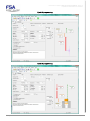
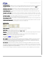
5.4.2
Cycles
When you select the Setpoint/Cycles menu, or click the
5.4.2.1
button, the Cycles page appears:
Description of fields
Chaining # if Ok: At the end of this cycle, if you want MVAT to chain to another "SOFT chaining" cycle, enter the Cycle
number here (1 to 384).
The current cycle number is of course not allowed (a cycle cannot loop back on itself!).
Chaining may be contingent on a validation by the PLC (in this case check the "I/O validation needed for resume" box)
Warning, if the current cycle does not execute successfully, chaining will ONLY be carried out if "Cycle resume if Nok"
is checked.
By Default, the pre-entered value is 0 which means NO CHAINING
Chaining # if NOk: If the current cycle does not execute successfully but nevertheless you still want MVAT to chain to
another "SOFT chaining" cycle, enter the Cycle number here (1 to 384).
The current cycle number is of course not allowed (a cycle cannot loop back on itself!).
Chaining may be contingent on a validation by the PLC (in this case check the "I/O validation needed for resume" box)
By Default, the pre-entered value is 0 which means NO CHAINING
Nb of Loop: If you want to repeat a chain x times (e.g. running in a slide by executing Cycle 1 Cycle 2 1 2 1
… x times), enter x in this field for the 1st cycle of the loop.
You can loop more cycles. For example, you want to loop a chain 10 times 123412… To do this enter 10 in
Nb of Loop for Cycle 1 only.
By Default, the pre-entered value is 0 which means: NO LOOPING
The maximum number depends on the number of cycles in the loop, as the MVAT can only chain 100 cycles in the
same sequence.
Rhapsodie.net – User Guide
2013-09
26/130
This document is the property of FABRICOM SYSTEMES D'ASSEMBLAGE and may not
be reproduced or disclosed without their authorisation
Holding time: At the end of a cycle, at the moment the pin comes to a stop depending on the speed and the
mechanical stiffness of the assembly, there may be an "overshoot" of the force due to inertia.
Two forces are then used for checking the final force: the peak force and the residual force.
Force
Peak force (overshoot)
Residual force
Trip setpoint
Holding time
Time
The holding time therefore allows the mechanics to "relax".
By Default, the pre-entered value is 0.00. 0.5 secs is usually sufficient to relax the mechanics.
The maximum programmable value depends on the type of pin, the overall cycle time and the force applied relative to
the nominal force of the press. In general, 1.5 secs is the maximum. Beyond this, the pin applies the force
continuously and the motor will overheat. Time must therefore be allowed for it to cool down.
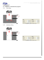
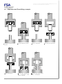
Cycle Type: Allows you select the cycle time from: (the graphical design change depending the choice)
- Press-Fitting:
Standard press-fitting cycle. The programmed positions are absolute.
- Acquisition:
Same as Press-Fitting BUT the trip position is kept in memory to enable DIFFERENTIAL
CHECKS to be carried out on position in the following cycles (whether or not within the
same sequence) (see advanced functions)
- Positioning:
Press-fitting cycle where ALL programmed positions are DISTANCES. Positioning is then
relative to the preceding cycle.
Note: A sequence CAN NEVER start with a positioning cycle.
Execution dir.: Allows you select the working direction: (the graphical design change depending the choice)
- Pressing:
The press shaft will exit and views a shaft pressing force as a "positive" force.
- Pulling:
The press shaft will return and views a shaft pulling force as a "positive" force.
Note: A sequence CAN NEVER start with a pulling cycle.
Note: FABRICOM pins work both in pressing and pulling mode without force limitation.
Trip force: This is the Force setpoint which will stop the press if the trip position has not yet been reached.
NEW : If the checkbox « Force Increment » is checked, the entered force here corresponds to a complementary force
that the press will add to the last force reached (the one of the last cycle).
The minimum configurable force is 1% of the nominal force for the press. Warning, to ensure accuracy in stopping
under force and reading the force, this value must be less than 10% of the nominal force of the press.
The maximum configurable force is the Pressing calibration force (see Specifications page).
WARNING :In traction mode, this is that value which is used as safety force during approach phase.
Max. and Min. force: These are the acceptance tolerances of the force at the end of execution (Peak force OR
Residual force depending on the "Quality checking on" selection).
By Default, the pre-entered value is 0.0 daN which means: NO CHECKING
Quality checking on: see above. Depending on the selection. in the results block (see section "Journal 232"), either the
Peak force, or the Residual force will be monitored with regard to quality information (OK, TB, TL).
Trip position: This is the Position setpoint which will stop the press if the trip force was not reached beforehand.
There is no minimum or maximum value, this depends on the geometric identification learnt by the MVAT during
calibration.
PLEASE NOTE: The value 0.000 MEANS "Position NOT programmed"
Trip position Max. and Min.: These are the acceptance tolerances for the position at the end of execution.
By Default, the pre-entered value is 0.000 mm which means: NO CHECKING
Rhapsodie.net – User Guide
2013-09
27/130
This document is the property of FABRICOM SYSTEMES D'ASSEMBLAGE and may not
be reproduced or disclosed without their authorisation
Max. current: This is the maximum current that the MVAT will allow the servo to carry out its requests. If this value is too
low relative to the work requested (application of force, acceleration, deceleration), the current limitation may cause
undesirable behaviours:
- the shaft remains in support position until the max. cycle time has elapsed
- the shaft accelerates slowly
- the shaft brakes incorrectly in the deceleration phase.
By Default, the pre-entered value is 100.0 %. This value may be reduced depending on the work requested, but be
careful of the acceleration and deceleration phases which often necessarily consume more energy due to the cycle
time, even for cycles where a very low force is applied.
Speeds and position: The cycle page diagram in Rhapsodie represents each of these parameters.
The default values are:
- Approach speed: 100% (fast approach: no time to lose! You must, however, take into account accelerations, the
velocity of the FSA pins and the weight of the tool carried)
- Working speed: 30% (we are press-fitting, some energy is required!)
- Trip speed: 5% (if we want to stop cleanly and minimise overshoot, or ensure the trip position is accurate, we need
to finish gently!)
- Return speed (ditto Approach speed)
Note: As most of the FSA pins are fast (from 330 mm/sec to 700 mm/sec), the speed entered as a percentage is
translated into mm/sec for illustrative purposes.
The Approach position represents the position at which the Approach speed changes to the Working speed.
The Slowing down position represents the position at which the Working speed changes to the trip speed.
Acceleration control and Acc./decel. dist.: To save on mechanics, and taking account of the speed and sensitivity of
FSA pins, it is recommended to introduce acceleration and deceleration ramps by enabling this function.
By Default, the pre-entered value is 5.000 mm. This means that the MVAT will carry out the change of speed over 5
mm of movement.
Activity of this ramp:
Change from:
Start speed*
Approach speed
Working speed
Trip speed
Stop
Return speed
to:
Approach speed
Working speed
Trip speed
Stop
Return speed
Start speed*
Ramp enabled?
YES
YES
YES
NO
YES
YES
*(see Advanced Functions - Specifications Page)
Store the Curve: If during the movement described by the current cycle, you wish to store the force as a function of
displacement, just check this box AND allocate a curve program (PROFILE) to the sequence which manages the
execution of this cycle.
Auto Return: if this cycle is the last in the sequence you can either:
- check this box and MVAT manages the return to the origin
- request SOFT chaining on special cycle 513
- use HARD chaining by the PLC which will request the same special cycle 513.
I/O validation needed for resume: if this box is checked, the MVAT awaits synchronisation from the PLC to chain to the
following cycle. Otherwise, chaining will be carried out directly.
Cycle resume if Nok: if this box is checked, the MVAT will continue with the chains even if the cycle just executed was
not OK. The quality of this cycle is thus forced to OK in order to continue. However, in the result block, the actual
quality will be displayed.
Rhapsodie.net – User Guide
2013-09
28/130
This document is the property of FABRICOM SYSTEMES D'ASSEMBLAGE and may not
be reproduced or disclosed without their authorisation
5.4.3
Profiles
When you select the Setpoint/Profiles menu, or click the
button, the Profiles page appears:
This menu allows you to carry out an advanced curve check. To configure this check, 5 force recording ranges are
available. Once the recording ranges have been defined, up to 5 check windows in total may be configured split
across the recording ranges.
Recording range no. 2
Recording range no. 1
Check window no. 2
Check window no. 1
Check window no. 3
Positioning modes of recording ranges:
- Absolute Start, Absolute End
- Start on force threshold and End at a fixed width from the start
- Start on External signal and End at a fixed width from the start
Positioning modes of check windows:
- Start of Window:
- Absolute
- Fixed width relative to the end
- On force threshold exceeded in increasing direction
- On force threshold exceeded in increasing direction
- Relative to the end of the preceding window
- End of Window:
- Absolute
- Fixed width relative to the start
- On force threshold exceeded in increasing direction
- On force threshold exceeded in increasing direction
- Relative to the start of the next window
- Relative to the last point recorded in the window
Rhapsodie.net – User Guide
2013-09
29/130
This document is the property of FABRICOM SYSTEMES D'ASSEMBLAGE and may not
be reproduced or disclosed without their authorisation
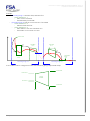
Example:
- Recording range 1: Absolute Start, Absolute End
- Check window no. 1:
- Start of force threshold
- End defined by Fixed width
- Recording range 2: Start of force threshold - Fixed width
- Check window no. 2:
- Absolute Start and End
- Check window no. 3:
- Start relative to the end of window no.2
- End relative to the end of the curve
Curve end
start
Chk. Win
no. 1
Chk. Win.
no. 2
start
end
Threshold:
force
Chk. Wd
no. 3
Recording range no. 2
Recording range no. 1
4 force values can be configured for each check window giving a trapezoidal shape:
Fmax start
Fmax end
Check
window
Fmin end
Fmin start
End
Rhapsodie.net – User Guide
Start
2013-09
30/130
This document is the property of FABRICOM SYSTEMES D'ASSEMBLAGE and may not
be reproduced or disclosed without their authorisation
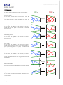
Control modes:
A control mode is selected for each check window:
Inclusion mode:
In this mode, all the points on the curve must be
inside the window.
The "Strict Inclusion" option invalidates the point on
the end of the window.
Increasing mode
In this mode, in addition to an inclusion, a check is
made that the start point of the window is less than
that of the end.
Decreasing mode
In this mode, in addition to an inclusion, a check is
made that the start point of the window is greater than
that of the end.
OK
NOK
Inclusion
Increasing
Decreasing
Peak mode
In this mode, in addition to an inclusion, a check is
made that the maximum of the curve corresponds to a
peak (increasing before the peak, then decreasing
afterwards).
Trough mode
In this mode, in addition to an inclusion, a check is
made that the minimum of the curve corresponds to a
trough (decreasing before the trough, then increasing
afterwards).
Mean mode (static)
In this mode, a check is just made that the mean of
the curve between the start and the end of the window
is between a max and a min.
Dynamic mode
In this mode, the dynamic mean is calculated and a
check is made that the new curve is included in the
check window.
Rhapsodie.net – User Guide
2013-09
Peak
Trough
xmax
Average
Static
xmin
Average
Dynamic
31/130
This document is the property of FABRICOM SYSTEMES D'ASSEMBLAGE and may not
be reproduced or disclosed without their authorisation
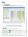
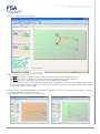
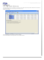
5.4.3.1
Configuring recording ranges
The programs are numbered from 2017 to 2099 (Warning, the scroll bar numbers them from 1 to 84).
The screens on this page also allow the user to carry out configuration by entering data as well as moving points using
the mouse.
Handles
To the left, the boxes allow the user to enter the start and end positions of the recording ranges.
To remove or add a recording range, you must uncheck the "Lock/Unlock" box to increase or decrease the number of
ranges.
The "1 Stor. Wnd/Cycle" box causes a new storage range to be used at each new cycle executed (and where curve
storage is required).
The "Quality Checking" box ensures that the quality of the curve check is taken into account.
If this box is not checked, the quality of the curve check will always be OK.
The drop-down menu present in each "Stor. Wd X" area allows you to select the start mode for storing the force:
If "Absolute" if chosen, the Start and End positions must be entered.
If "Threshold" is chosen, a new "Threshold" box is displayed to enter the threshold
force from which storage is to start. The Threshold force then appears on the graph.
If "Trigger" is selected, force storage will be tripped by an ON/OFF input to the MVAT
card.
For both the last 2 modes, "Start position" and "End position" are replaced by "Width".
Repeatedly clicking a "Stor. Wd X" area alternately shows/hides the corresponding range on the graph.
Rhapsodie.net – User Guide
2013-09
32/130
This document is the property of FABRICOM SYSTEMES D'ASSEMBLAGE and may not
be reproduced or disclosed without their authorisation
The graph is automatically updated when values are entered in the boxes.
Similarly, if you move the "handles" available on each of the recording ranges, the corresponding value in the entry box
is updated:
The 2 boxes "Snap Y" and "Snap X" provide a coarser displacement increment on the handles.
For each recording range, the "Nb of ChkWd" field defines the number of check windows which will belong to this
recording range.
In total, a maximum of 5 check windows may be distributed across the Recording ranges.
To the side of the "Storing windows" tab, there are as many "ChkWd" tabs as requested check windows.
To configure the check windows, just click on the corresponding tab.
Configuration essentials: (to avoid execution errors)
- For a pressing cycle, the start position must be GREATER than the end position
- For a pulling cycle, the start position must be LESS than the end position
If 2 pressing cycles travel successively over the same area, it is possible to program 2 identical recording ranges:
e.g. Sequence of 3 cycles during which 2 identical split pins are fitted into a product at 2 different locations.
Sequence
Cycle 1 (force stor. requested)
Cycle 3 (force stor. requested)
Recording range 1
Recording range 2
Cyc 2
Rhapsodie.net – User Guide
2013-09
33/130
This document is the property of FABRICOM SYSTEMES D'ASSEMBLAGE and may not
be reproduced or disclosed without their authorisation
5.4.3.2
Using a envelope Curve to place the Recording Ranges (Storing Windows)
Since the version 1.5.0.00 of Rhapsodie, you can open a curve into profiles programming to help you to place the
recording ranges and the check Windows :
The start and the end of storing of the curve are displayed to help you to adjust the beginning and the end of the
recording ranges.
You can either open a standard curve, or an envelope curve generated by VisuCourbes.Net.
On the position axis, an auto-scale is done including the curve and your recording ranges.
On the Force axis, the scaling is done on the nominal Force of the sensor of the press
Rhapsodie.net – User Guide
2013-09
34/130
This document is the property of FABRICOM SYSTEMES D'ASSEMBLAGE and may not
be reproduced or disclosed without their authorisation
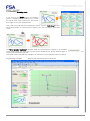
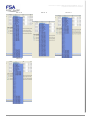
5.4.3.3
Configuring check windows
Handles
There are 4 areas in this screen:
- the "Start" area used to configure the start of the window with regard to both position and force
- the "End" area used to configure the end of the window with regard to both position and force
- the "Mode" area which defines the type of check to be carried out in this window.
- the graph area which gives a dynamic representation of the configuration and has the same background colour as
the recording range to which it applies. The maximum and minimum positions of the graph relate to the start and
end positions of the recording range.
Since the version 1.5.0.00 of Rhapsodie.Net, if you have opened a curve into the “Storing Windows” sheet, you will see
in each Check Window the part of this curve :
In our example in 4.4.3.2, there is 2 Check Windows :
Rhapsodie.net – User Guide
2013-09
35/130
This document is the property of FABRICOM SYSTEMES D'ASSEMBLAGE and may not
be reproduced or disclosed without their authorisation
Graph manipulation
The graph and the entry fields are fully interactive through the handles available on the graph (4 angles in the window
and the bounds of the 2 force thresholds).
Modifications made to the entry fields are reproduced directly in the graph, and manipulating the graph updates the
entry fields.
If you right-click inside the graph, a pop-up menu appears:
You can zoom in on the graph, or display it in full scale (the Y scale is not affected, but the X
range takes in the full stroke of the pin).
On the next right-click, the pop-up menu becomes:
"Auto Scale" returns to the initial window (the Y axis starts from 0 daN and goes up to the
nominal force for the pin, on the X-axis, the area related to the recording range is displayed)
In Zoom mode, scroll bars appear at the sides which allow you to move around the graph, and the symbols
you to zoom out (the various Zooms are saved)
allow
Trip modes for the start and end of the window:
This allows the start and end of the window to be positioned.
Start
Mode
End
Values to enter
Mode
Values to enter
Absolute
Start position
Absolute
Enter the end position
Fixed width/end
Window width
Fixed width/start
Window width
Force threshold +
Force threshold -
Offset, start position and end
threshold, Tripping force
Offset, start position and end
threshold, Tripping force
End of prev. window
Offset
Linear regression
Offset, start position and end of
observation
Force threshold +
Force threshold -
Curve end
Offset, start position and end
threshold, Tripping force
Offset, start position and end
threshold, Tripping force
Offset
Some examples of the various programs are shown on the next page.
Rhapsodie.net – User Guide
2013-09
36/130
This document is the property of FABRICOM SYSTEMES D'ASSEMBLAGE and may not
be reproduced or disclosed without their authorisation
Selection of the Checking mode
If you click on the "Mode" button, the following
screen is displayed and enables you to select
the type of check to be carried out in the window
by a single click on the desired button.
Then, with the model selected, passing the mouse over the "NOK View" button,
shows an example of a failed check in place of the icon showing a successful
check.
The "Strict Inclusion Activated" checkbox adds the Strict Inclusion criterion to the Inclusion
check. In this mode, the curve may not exit from the window by the "End of window" edge, or
check will be declared as Not OK.
This mode makes it possible for example to check that a curve terminates within the window.
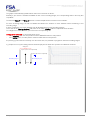
Programming examples:
Rhapsodie.net – User Guide
the
Absolute start and End on Force Threshold
2013-09
37/130
This document is the property of FABRICOM SYSTEMES D'ASSEMBLAGE and may not
be reproduced or disclosed without their authorisation
Example no. 2: Start on force threshold and End at a fixed width from the start
Example no. 3: Start fixed width from the end and End placed relative to the end of the curve.
Rhapsodie.net – User Guide
2013-09
38/130
This document is the property of FABRICOM SYSTEMES D'ASSEMBLAGE and may not
be reproduced or disclosed without their authorisation
Configuration essentials: (to avoid execution errors)
- For a pressing cycle, the start positions (start of window and threshold starts) must be GREATER than the end
position (window end and threshold ends)
- For a pulling cycle, the start positions (start of window and threshold starts) must be LESS than the end positions
(window end and threshold ends)
- The offset is signed: +5 mm means: the window starts 5 mm AFTER the trip, -5 mm means: the window starts 5
mm BEFORE the trip
- The width MUST BE POSITIVE (Fixed Width mode)
- Depending on the trip mode, the values of the active "Start" and "End" positions must be within the recording range
(the graphical representation allows this to be checked simply).
- All Force values must be less than the press calibration force
- It is prohibited to select a "Fixed width/End" start trip mode and a "Fixed width/start" end trip mode
The List tab shows all advanced curve programs in the same way as in the other pages.
Rhapsodie.net – User Guide
2013-09
39/130
This document is the property of FABRICOM SYSTEMES D'ASSEMBLAGE and may not
be reproduced or disclosed without their authorisation
5.4.4
Page: "Sequences"
When you select the Setpoint/Profiles menu, or click the
button, the Profiles page appears:
This menu allows you to allocate the number of the 1st cycle executed to a sequence as well as the storage program
number (PROFILE).
It is possible to view the cycle chain (soft only) by pointing to the row header of a sequence:
For the meaning of the colour code, see the section entitled "Use of List pages\Consistency"
Rhapsodie.net – User Guide
2013-09
40/130
This document is the property of FABRICOM SYSTEMES D'ASSEMBLAGE and may not
be reproduced or disclosed without their authorisation
5.5
5.5.1
Examples of conventional programs
Press-fitting
22
0
Fbinding ≈ 1000 daN
15
Fsecuring ≈ 6000 daN
0
Programming of the related cycle
5.5.2
Interference fitting
22
0
Fbinding ≈ 1000 daN
15
0
Programming of the related cycle
Rhapsodie.net – User Guide
2013-09
41/130
This document is the property of FABRICOM SYSTEMES D'ASSEMBLAGE and may not
be reproduced or disclosed without their authorisation
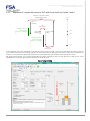
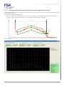
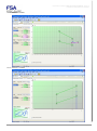
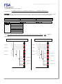
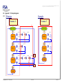
5.5.3
Sequence of 3 cycles with return by PLC and Curve check on Cycles 1 and 3
Sequence 1 (program number
requested by the PLC)
Position
Cycle 1:
Pick part
PLC
authorisation
Storage of force to
check picking
(profile no. 17, Range
1)
Cycle 2:
Release
Cycle 3: Pressfitting
50.000
40.000
Storage of force to
check press-fitting
(profile no. 17, Range
2)
5.000
PLC
authorisation
In this example, the press descends to position 40, picks a part of height 15 mm then goes back up with the part 10
mm, relative movement. The feeding cylinder can then return and the PLC gives the order to the press to continue the
sequence. The press then descends to press-fit the part under force (the position reached is about 5 mm).
We shall present all the Cycle, Profile and Sequence pages needed to carry out this process as well as the curve
obtained (the comments give more information on certain choices
Cycle 1 programming
Rhapsodie.net – User Guide
2013-09
42/130
This document is the property of FABRICOM SYSTEMES D'ASSEMBLAGE and may not
be reproduced or disclosed without their authorisation
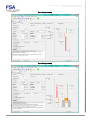
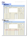
Cycle 2 programming
Cycle 3 programming
Rhapsodie.net – User Guide
2013-09
43/130
This document is the property of FABRICOM SYSTEMES D'ASSEMBLAGE and may not
be reproduced or disclosed without their authorisation
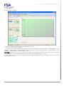
Programming of the storage program: Profile:
Check window no. 1
Rhapsodie.net – User Guide
2013-09
44/130
This document is the property of FABRICOM SYSTEMES D'ASSEMBLAGE and may not
be reproduced or disclosed without their authorisation
Check window no. 2
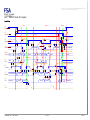
Programming of the sequence
Associated result block:
*****************************************
Station/Channel/Addr :000.000.001.237.160.136.001
D/M/Y , H/M/S
:26/04/2012 14/58/38,11
Total seq. time:
19.10 s
Pin. Temp:
24.96 Deg.
Module temp.:
45.96 Deg.
Sequence number:
1
Active Curves Check OK
Sequence OK
Result Number:
203843
Cyc. no. before Greasing:
99863
Curve number:
17
Cycle number:
3
Rhapsodie.net – User Guide
2013-09
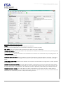
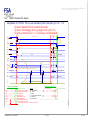
START of RESULT BLOCK – Overall sequence block
This is the rack identification entered in Rhapsodie's Units page.
This is the program number (sequence) requested from the MVAT card by the PLC
There is a curve check program associated with this sequence. Its quality is active and OK.
The sequence is OK: all the executed cycles were OK and the curve check was also OK
Incremented for each part produced. Cannot be reinitialised
Count down to greasing configured on Specifications/Maintenance page
No. of curve program associated with the sequence
Number of cycles executed during the sequence
45/130
This document is the property of FABRICOM SYSTEMES D'ASSEMBLAGE and may not
be reproduced or disclosed without their authorisation
----------------------------------------Cycle number:
1
Form number:
1
Press-fitting pressing cycle OK
Cycle Time:
1.57 s
Previous position:
5.112 mm
Position reached:
42.217 mm OK
Peak force:
51.7 daN OK
Residual force:
50.5 daN
Position difference:
37.104 mm OK
----------------------------------------Cycle number:
2
Form number:
2
Pulling cycle positioning OK
Cycle Time:
0.92 s
Previous position:
42.217 mm
Position reached:
52.257 mm OK
Peak force:
3.7 daN OK
Residual force:
0.9 daN
Position difference:
10.040 mm OK
----------------------------------------Cycle number:
3
Form number:
3
Press-fitting pressing cycle NOT OK
Cycle Time:
2.85 s
Previous position:
52.257 mm
Position reached:
5.644 mm OK
Peak force:
504.2 daN OK
Residual force:
481.1 daN
Position difference:
-46.612 mm OK
Curve check OK
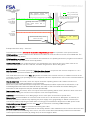
-----------------------------------------
Start of 1st CYCLE BLOCK
*****************************************
Curve Check: Curve Profile N0:
17
"WINDOW" RESULT BLOCK
First Cycle executed'
Cycle no. in Rhapsodie
Cycle type: Press-fitting, direction: Pressing, quality OK
Execution time of this cycle
Position reached in the previous cycle
Final position'
Final force (overshoot peak)
Final force at the end of the holding time
Difference between the final position and the previous position, or the initial position (see Rhapsodie/Cycles)
Start of 2nd CYCLE BLOCK
Second Cycle
C'
Cycle type: Positioning (relative movement), Direction: Pulling, Quality OK
Start of 3rd CYCLE BLOCK
As the curve check has been completed in this cycle, the result is displayed
No. of curve control program. Type: PROFILE (no. > 16)
----------------------------------------1st Window
Start Increasing Threshold - End Fixed Width - Pressing Inclusion Mode
F 01; Fmax:
45.4 daN; Crv <= Max: OK; Fmin1:
25.3 daN; Crv >= Min: OK
2nd Window
Start Increasing Threshold - End Fixed Width - Pressing Inclusion Mode
F 02; Fmax:
200.8 daN; Crv <= Max: OK; Fmin1:
150.6 daN; Crv >= Min: OK
*****************************************
Pitch number:
13
COM2 OK
The curve was sent to the PC. Transmission OK
Waiting for cycle start release
Presence Index
The pin shaft has returned to the origin position. The index (inductive sensor is present)
Idle position
The shaft has reached its origin, idle position, PULSE-1
Pitch number:
1
Awaiting Cycle Start
The card is ready again, awaiting Cycle Start.
Rhapsodie.net – User Guide
2013-09
46/130
This document is the property of FABRICOM SYSTEMES D'ASSEMBLAGE and may not
be reproduced or disclosed without their authorisation
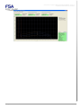
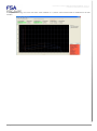
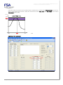
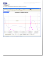
Curve obtained:
Rhapsodie.net – User Guide
2013-09
47/130
This document is the property of FABRICOM SYSTEMES D'ASSEMBLAGE and may not
be reproduced or disclosed without their authorisation
5.5.4
Sequence with a "Looping" phase then a "Check" phase
Sequence 2 (program number
requested by the PLC)
Cycle 10:
Descent,
support
Position
Return
origin
Hard Chaining
on Sequence 3
52.000
Cycle 20:
Release
Cyc10 Cyc20 Cyc10 Cyc20
Cycle 30: Final
check
Storage of force
for checking
(profile no. 20)
40.000
30.000
In this example, we descend to an elastic product to carry out 3 "gymnastics", then carry out a check cycle, then return
to the origin automatically
Cycle 10 programming
Rhapsodie.net – User Guide
2013-09
48/130
This document is the property of FABRICOM SYSTEMES D'ASSEMBLAGE and may not
be reproduced or disclosed without their authorisation
Cycle 20 programming
Cycle 30 programming
Rhapsodie.net – User Guide
2013-09
49/130
This document is the property of FABRICOM SYSTEMES D'ASSEMBLAGE and may not
be reproduced or disclosed without their authorisation
Force storage programming: Profile no. 20
Programming of sequences 2 and 3
Rhapsodie.net – User Guide
2013-09
50/130
This document is the property of FABRICOM SYSTEMES D'ASSEMBLAGE and may not
be reproduced or disclosed without their authorisation
5.5.5
Sequence with single press-fitting with a narrowly-targeted curve check
This example illustrates how to program a complete part check (threshold in cycle, profile during press-fitting, test of
length press-fitted, etc.)
The checks requested are as follows:
- On a force threshold of 100 daN, start a profile with checking of an increasing phase and a decreasing phase.
- Check the length of the part (22.5 mm +/-1 mm) relative to the threshold of 100 daN
22.5+/- 1 mm
100 daN
1.5 mm
Resulting curve
Rhapsodie.net – User Guide
2013-09
51/130
This document is the property of FABRICOM SYSTEMES D'ASSEMBLAGE and may not
be reproduced or disclosed without their authorisation
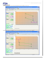
Cycle programming
Profile programming: Recording range
Rhapsodie.net – User Guide
2013-09
52/130
This document is the property of FABRICOM SYSTEMES D'ASSEMBLAGE and may not
be reproduced or disclosed without their authorisation
Check windows: ChkWd1
Check windows: ChkWd2
Rhapsodie.net – User Guide
2013-09
53/130
This document is the property of FABRICOM SYSTEMES D'ASSEMBLAGE and may not
be reproduced or disclosed without their authorisation
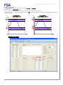
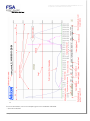
Check windows: ChkWd3
It can be seen that the 2 roles of windows 1 and 2 are as follows:
- check the increase and decrease
- check that the length of the part is a minimum of 21.5 mm (Start Offset + width ChkWd1 + width ChkWd2 = 21.5)
Window 3, configured in strict inclusion mode, ensures that the part does not exceed 22.5 mm (Start Offset + width
ChkWd1 + width ChkWd2 + width ChkWd3 = 22.5)
WARNING: on the curve for the correct part, we note that the representation of the 3rd check window does not relate to
the configuration: it should be 2 mm wide, while it is in fact only 1.628mm (17.073 – 15.445).
This is because the last check curve is always represented with its end brought back to the last point on the curve. We
will therefore never see:
Rhapsodie.net – User Guide
2013-09
54/130
This document is the property of FABRICOM SYSTEMES D'ASSEMBLAGE and may not
be reproduced or disclosed without their authorisation
Rhapsodie.net – User Guide
2013-09
55/130
This document is the property of FABRICOM SYSTEMES D'ASSEMBLAGE and may not
be reproduced or disclosed without their authorisation
If the part is too long, the curve exits from check window no. 3, and a strict inclusion fault is obtained on the last
window:
Rhapsodie.net – User Guide
2013-09
56/130
This document is the property of FABRICOM SYSTEMES D'ASSEMBLAGE and may not
be reproduced or disclosed without their authorisation
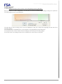
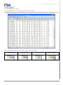
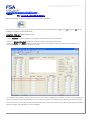
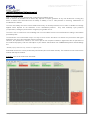
5.5.6
Page: "Results": (field bus only)
This menu allows the user to configure the construction of the table of press-fitting results obtained from the MVAT in
the network coupler. These results may be retrieved by the PLC.
Single List (by default):
Various selection lists of the values received are available:
For more information on retrieving results, see the "Results" section
Rhapsodie.net – User Guide
2013-09
57/130
This document is the property of FABRICOM SYSTEMES D'ASSEMBLAGE and may not
be reproduced or disclosed without their authorisation
List no. 2
List no. 3
List no. 4
List no. 5
Rhapsodie.net – User Guide
2013-09
58/130
This document is the property of FABRICOM SYSTEMES D'ASSEMBLAGE and may not
be reproduced or disclosed without their authorisation
5.5.7
Help Menu
5.5.7.1
Rhapsodie Guide
This gives direct access to the User Guide in PDF format.
5.5.7.2
MVAT fault List
Since the V1.6.0.00 Rhapsodie.Net version, a MVAT fault list is available directly in Rhapsodie thanks to this menu.
Rhapsodie.net – User Guide
2013-09
59/130
This document is the property of FABRICOM SYSTEMES D'ASSEMBLAGE and may not
be reproduced or disclosed without their authorisation
5.5.7.3
"UE references page"
This page displays all the press-fitting pins in the Fabricom range.
It is essential to select the correct pin for each new UE created in the Press-fitting Units page, as a number of settings
are pre-entered depending on the unit selected. The values used to pre-enter these fields come from this table.
When you pass the mouse over the small columns on the right you see:
creation date
Rhapsodie.net – User Guide
modification date
2013-09
person who changed the
reference.
Status (locked?)
60/130
This document is the property of FABRICOM SYSTEMES D'ASSEMBLAGE and may not
be reproduced or disclosed without their authorisation
Creating a new UE:
The list of UEs is not fixed and it is possible to add UEs with characteristics which are specific to them. To do this, you
can:
Add a UE
Delete a UE
Locking a UE:
After creating a new UE, it is possible to lock it to avoid the risk of deletion. To do this, select the UE then right-click it
Then use the "Lock" command
WARNING: once locked, it will not be possible to delete this UE.
You will only be able to reinitialise the database by retrieving the original file from the Rhapsodie.net installation CD.
5.5.7.4
Page: "About..."
Allows the Software Licence to be registered and to find out which version is installed.
Before and after registering the software:
Rhapsodie.net – User Guide
2013-09
61/130
This document is the property of FABRICOM SYSTEMES D'ASSEMBLAGE and may not
be reproduced or disclosed without their authorisation
6 Advanced usage
6.1
Using Rhapsodie.Net: General principles
Do not open multiple screens, navigate with screens
6.1.1
Project Storage directories
Rhapsodie projects are stored in the directory of your choice.
Let's take, for example, the directory: D:\FSA\Presses\
Within this directory, we will find the following structure:
D:\FSA\Presses\Line1\ OP110
OP120
OP130
OP140
Line2\ OP210
OP220
OP230
In each of the OPxx directories, you will find:
-
The "project" file: .PJR
The "Stations" directories (1 per station created in the project)
Under each Station directory, as many "UE" directories as press-fitting units created
Under each UE directory:
You will find all the xml files containing the cycles, sequences, profiles, etc.
The "Curves" directory contains all the curves stored during production when the PC was connected to the MVAT card.
Rhapsodie.net – User Guide
2013-09
62/130
This document is the property of FABRICOM SYSTEMES D'ASSEMBLAGE and may not
be reproduced or disclosed without their authorisation
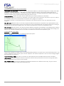
6.1.2
Opening a project directly
If you don't want to change the data for a project, but just open Rhapsodie to view the curves produced for example,
just double-click the corresponding .PJR file.
When you do this, Rhapsodie starts up with the unit page for the first station in the project, and the COM_MVAT
communication interface starts along with VisuCourbes:
In this example, the "C" box is checked, so VisuCourbes has been started.
The
button is on a red background: the MVAT card related to the unit selected will not send curves at the end of
the sequence.
If you want to view the curves being produced, just click this button (Warning, NOT DURING PRODUCTION!), the
modification is sent to the MVAT card and on the next sequence, the MVAT card will send the curves.
The button then changes colour:
6.1.3
Upload/Import/Export
To use these functions, you must be logged on as "Creator"
These functions allow you to:
- Interrogate an MVAT card (UPLOAD) to retrieve the programs contained within it
- Replace the programs for the selected UE (IMPORT) by those retrieved from the MVAT card
- Export the programs for the UE selected in order to retrieve them onto another UE for example.
6.1.3.1
Upload (Retrieval of programs from MVAT)
After selecting the UE concerned, just select the following menu option:
or click the button
Then, the order is sent to the MVAT card. In reply, it will send all its programs.
When this send is finished, a message appears on the screen showing the name of the .txt file.
The programs will therefore be stored in the form of a txt file in the "Upload" directory for the unit concerned.
6.1.3.2
Import
All that remains to be done is to import the txt file.
Before doing this, ensure all program pages are closed (Cycles, Sequences, Profiles, Specifications) to leave only the
"Units" page.
You then select the unit involved, select the Project\Import menu and choose the desired txt file.
At the end of the import, all the programs for the selected unit are replaced by those in the txt file.
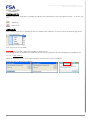
6.1.3.3
Export
This function allows all the programs for the selected UE to be exported to a text file.
This txt file may be re-imported in the same way as a txt file from an Upload.
Rhapsodie.net – User Guide
2013-09
63/130
This document is the property of FABRICOM SYSTEMES D'ASSEMBLAGE and may not
be reproduced or disclosed without their authorisation
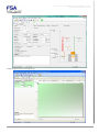
6.1.4
Sending programs
To use these functions, you must be logged on as "Creator"
Each time a program is modified (Cycles, sequences, Profiles, Specifications), in order for the MVAT card to take into
account the changes, you have to:
-
Save the page being modified in Rhapsodie by pressing on the button
-
Send the new programs to the MVAT card by pressing on the button
After each send has completed, a window shows the result of the download:
The correct result is: "Download to MVAT terminated: OK"
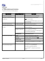
The following failure messages have the following meanings:
- "Download to MVAT terminated: Timeout on transmission"
ComMVAT is not started
The RS485 connection between the PC and Port COM2 of the MVAT is defective
The MVAT card is not ready (in production?)
- "Download to MVAT terminated: Too many NAcks"
The MVAT card has rejected the send (see the error number in the journal window of the ComMVAT
module)
6.1.4.1
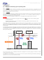
Case of communicating through an UExp-MVAT panel
If the machine is equipped with an UExp-MVAT panel (operating panel at the station, see §*5.10***), before
sending the programs to the MVAT, Rhapsodie.Net send to the MVAT controller an authorization request, to check that
nobody modified the programs using the panel, in which case Rhapsody would most updated.
If you are in this case, a message box appears:
Then, the user has to decide between send notwithstanding (and then overwrite the modifications made from
the panel), or cancel and update Rhapsodie programs with the “Upload from MVAT” button and the “Import” menu.
(see §6.1.3 Upload/Import/Export p63).
Rhapsodie.net – User Guide
2013-09
64/130
This document is the property of FABRICOM SYSTEMES D'ASSEMBLAGE and may not
be reproduced or disclosed without their authorisation
6.1.5
Using the "List" pages
6.1.5.1
Copy/Pasting
The Cycles, Profiles and Sequence pages include a presentation of the data in the form of a table.
This more compact but less readable presentation allows quick and efficient copy-pasting.
For example, to duplicate cycle 1 (1001) 5 times to cycles 5 to 9, select row 1001 and right-click/copy
Then select rows 5 to 9 and right-click/paste
You can also select say a hundred or so cycles, copy and paste them into an Excel file, carry out bulk changes and
paste them back into our list. (be careful however of certain values which are calculated by Rhapsodie from various
checkboxes - the "Flag" columns in general)
6.1.5.2
Initialize (previously “Delete”)
This feature initialize all the values, for the pages “Cycles”, “Curves”, “Profils” and “Sequences”.
6.1.5.3
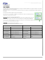
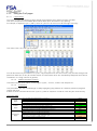
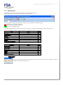
Consistency
This presentation also has the advantage of clearly highlighting any problems of consistency between programs
created and used.
It allows a colour to be allocated to each cycle no., profile or sequence in order to check they are used correctly:
COLOUR CODE
Cycle
Page
Profile
page
Sequence
page
Cycle programmed and allocated to a sequence
Cycle allocated to a sequence but NOT programmed
Cycle programmed but not allocated to a sequence
Cycle NOT programmed and NOT allocated to a sequence
Curve programmed and allocated to a sequence
Curve allocated to a sequence but NOT programmed
Curve programmed but not allocated to a sequence
Curve NOT programmed and NOT allocated to a sequence
Sequence OK
Sequence with cycle or curve NOT programmed
Sequence which loops back on itself (e.g. sequence 1 is allocated to cycle 1 which is
chained to cycle 2 which is itself chained to cycle 1)
Cycle, curve or sequence number in error
Sequence not programmed
Rhapsodie.net – User Guide
2013-09
Green
Red
Beige
White
Green
Red
Beige
White
Green
Red
Salmon pink
Beige
White
65/130
This document is the property of FABRICOM SYSTEMES D'ASSEMBLAGE and may not
be reproduced or disclosed without their authorisation
6.2
How to backup projects
Just save the project directories(s) (D:\FSA\Presses in our example)
6.3
How to retrieve a project on another PC
The simplest way is as follows:
- Copy the directory for the project in question (the one containing the station directory, the .PJR file and the .RAP
files, for example D:\FSA\Presses\Line1\Opxxx)
- Paste it into the PC\Destination directory (for example C:\My Documents\Presses\Line1\Opxxx)
Before the version V1.5.0.03, it’s still necessart to :
- Edit the .PJR file
- Change the following line:
<StationPath>D:\FSA\Presses\Line1\OPxxx</StationPath>
-
By updating the path to that for the new PC:
<StationPath>C:\My Documents\Presses\Line1\OPxxx</StationPath>
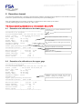
6.4
How to add/delete a Station to/from the project
In the Station page, a browser window lets you scroll through the various stations for the project.
The
button allows you to add a station, the
button allows you to delete it.
Afterwards, the procedure for saving the station with the passwords, path and name is the same as when it was
created.
6.5
How to add/delete a Press-fitting unit to/from the Station
In the Press-fit Units page, a browser window lets you scroll through the various units for the station.
The
button allows you to add a unit, the
button allows you to delete it.
Afterwards, the procedure for saving the unit with its name, identification, COM port, etc. is the same as when it was
first created.
Rhapsodie.net – User Guide
2013-09
66/130
This document is the property of FABRICOM SYSTEMES D'ASSEMBLAGE and may not
be reproduced or disclosed without their authorisation
6.6
Results
This chapter is under construction, as the Rhapsodie page is in modification.
6.7
Advanced functions
These pages become visible when the selection is checked:
From then on, when the specifications or Cycles pages are opened, one or more additional tabs are displayed.
6.7.1
Specifications page
6.7.1.1
"Appendix" tab
Rhapsodie.net – User Guide
2013-09
67/130
This document is the property of FABRICOM SYSTEMES D'ASSEMBLAGE and may not
be reproduced or disclosed without their authorisation
TECHNICAL FEATURES AREA:
Screw pitch: specifies the pitch of the roller screw in mm.
This field is only used by the MVAT card if the pin identification card is absent or defective.
To be entered only for pins which do not have an electronic identification or pins which do not appear in the "UE
references" list
In this case, refer to the manufacturer's data (Equipment references section of the maintenance manual)
Pass Band: Value in Hertz of the pass band of the instrumentation amplifier, processed by the software. The default
value is 1000 Hz.
Calibration current: specifies the maximum current that the speed controller can deliver during calibration in pressing
or pulling mode. This value as a percentage is limited to 99%.
Manual mode current: specifies the maximum current that the speed controller can deliver during a manual ascent or
descent. This value as a percentage is limited to 99%. For safety reasons as regards the mechanical environment of
the press-fitting pin, a maximum value of 10% is strongly recommended.
Return current: specifies the maximum current the speed controller can deliver during the return to the origin position.
This value as a percentage is limited to 99%.
Rated value for auxiliary: specifies the maximum of the range of a control auxiliary which can be connected to the
MVAT. For example, for a load cell delivering 10 mV under a full load of 100 kN, we will enter
10000 daN in this field.
"Flag" definitions
Send window results: If this box is checked, at the end of each sequence, the MVAT sends over the RS232 link the
results of checks carried out for each window defined in the storage program (curve).
Send curve to PC: If this box is checked, at the end of each sequence, the MVAT sends over the RS485 link the 2048
or 4096 points stored according to the storage programme (curve).
WARNING: the MVAT can take up to 1 second to build the curve block and this time has a direct effect on the cycle
time. Sending this block to the PC via the RS485 link can take up to 1.5 seconds. This does not affect the cycle time
and allows the "VisuCourbes" tool to draw the force/displacement curves.
WARNING: If no PC is connected during production, this box must be unchecked to avoid wasting time (the card
makes 3 attempts to send the curves)
Display results on PC: Function disabled
Detailed cycle time: If this box is checked, the time of the last cycle carried out is displayed in the result block of the
journal. If this box is not checked, the time displayed is the cumulative time from the start of the sequence.
Process control recorder: Monitoring mode for Fabricom After-sales service.
Press recorder: Monitoring mode for Fabricom After-sales service.
INPUT/OUTPUT AREA:
MVAT Multiplex max time (TMUX): specifies the maximum time allowed for multiplexing the inputs in automatic mode.
I/O Anti-aliasing time (TAR): specifies the anti-aliasing time for Inputs/Outputs
I/O Wraparound time (TRMin): specifies the MVAT minimum loop time
I/O min response time (Tack): specifies the minimum MVAT response time
Index filter: Allow the signal from the index (position detector) to be filtered by software to avoid the index being
detected while the shaft is not on this position. This value must be between 0 and 0.08s.
Brake opening Waiting Time: Adjusts the time allowed to the brake to open before carrying out the Offset
measurement at start-up. By default it is set to 400 ms.
"Flag" definitions
Working with Field Network: when checked means you are using a network such as PROFIBUS DP or ETHERNET for
the dialogue between MVAT and the PLC.
Multi index: Check the "Multi index" box to use the 4 "index offset" positions in the "Maintenance" tab.
Rhapsodie.net – User Guide
2013-09
68/130
This document is the property of FABRICOM SYSTEMES D'ASSEMBLAGE and may not
be reproduced or disclosed without their authorisation
Start cycle operating: validates the use of a "Cycle start" signal to launch either a press-fit sequence or a calibration, or
a manual raise or lowering operation. Apart from FABRICOM AFTER-SALES SERVICE, this box must always be
checked.
Ack needed in case of fault: when this box is checked in manual mode authorises continuation of execution with
acknowledgement in case of fault. To continue execution with acknowledgement in case of fault, do not check.
PLC I/O Management: this box switches from automatic mode to manual mode. Checked means automatic mode,
and unchecked manual mode.
Idle position on S5 output: when this box is checked, it activates the change of output S5 of the MVAT to level 1 when
the pin reaches its origin position. This field is greyed out and unchecked if the "Idle position from TDC" field is equal to
0.
Old PLC Compatible: this box allows disabling the fallen bit to 0 of « Cycle On» bit, between 2 cycles, SOFT chained
without API authorization. Only the quality of the last cycle is known by the PLC.
External stop on I5 enable: this box allows an external ON/OFF signal connected to input I5 to cause a trip rather than
a position or a force.
Keyboard controlling enabled: To directly control the press from the keyboard, this box must be checked. The control
commands are sent exclusively by a UExp-MVAT connected to the MVAT card.
SENSORS AREA:
Sensor rated value: rated value in daN of the Force sensor fitted to the press-fitting pin.
Sensor Class: OPTION. Authorises a limitation or overrun of the rated force
(1 by default otherwise AS AN OPTION value between 0.8 and 1.2)
Sensitivity: number of millivolts delivered by the force sensor for every 1 volt of power supply voltage when stressed to
its rated value. 1.000 mV/V is the default value.
Resolution: After the machine has been calibrated, the MVAT card calculates this value and displays it in the
calibration result block in the journal under the title "Resolution depl."
(See Appendix, Journal, calibration of bottom and top gages).
It must be updated by the user in Rhapsodie.net.
Max. resolution: Maximum value that the number of pulses/mm found during the calibration cycle must not exceed.
If the number of pulses/mm is greater than the maximum resolution, the calibration is not confirmed and the new
settings calculated are not taken into account by the MVAT which declares an incorrect calibration by output S6. A
check must be made that the gages are of the correct thickness.
Min. resolution: Minimum value that the number of pulses/mm found during the calibration cycle must not exceed.
If the number of pulses/mm is less than the minimum resolution, the calibration is not confirmed and the new settings
calculated are not taken into account by the MVAT which declares an incorrect calibration by output S6. A check must
be made that the gages are of the correct thickness.
Entry of the last two settings is essential to the operation of the machine. A fault is enabled if they are not specified.
Rhapsodie.net – User Guide
2013-09
69/130
This document is the property of FABRICOM SYSTEMES D'ASSEMBLAGE and may not
be reproduced or disclosed without their authorisation
FORCE AREA:
Offset fault Threshold: Value in daN of the maximum force offset tolerated at idle. If this value is exceeded, the card will
refuse to start a cycle and a fault number is shown in the result block (fault list ). A value equivalent to 10% of the rated
value of the sensor is recommended.
Pulling calibration force: Value in daN of the force used during pulling calibration of the machine. This value must be
greater than the largest pulling force programmed in the cycles and be between 0.25 and (1 times the rated - Offset
fault threshold).
Safety Return Force:
- Value in daN of the maximum force authorised during the return travel of the pin. During this return travel, the
force is continually checked and must not exceed this programmed value
- Value in daN of the maximum force authorised during the manual raise
TDC AREA
T.D.C. Max./ T.D.C. Min.: When carrying out a calibration without gages, these fields protect the quality and
consistency of the lower gage calibration.
Z R O (Offset from Actual Working Plane): This field offsets the Actual working plane (PTR), i.e. the "zero" obtained on
calibration (bearing surface of the lower gage) in a positive or negative direction to obtain a Virtual datum plane(PRV).
Upper gage = 100 mm
Virtual datum plane with an offset =
50 mm
Lower gage = 40 mm
Actual working plane (PTR)
Virtual datum plane with an offset = -15
mm
Coeff. Déform : : Provided that a external temperature sensor is connected to the spindle (to measure the temperature
of the frame for example), this coefficient is used to correct the press aperture when the ambient temperature evolves.
To help the user to evaluate pratically the value of this coefficient, it’s possible to make 2 calibrations at 2 different
temperature, and then, after the second calibration, the MVAT card calculate this coefficient and gives the result into
the terminal result. (only if a preliminary value has been entered first to activate this correction)
SPEEDS AREA:
Rhapsodie.net – User Guide
2013-09
70/130
This document is the property of FABRICOM SYSTEMES D'ASSEMBLAGE and may not
be reproduced or disclosed without their authorisation
Starting Speed: used at the start-up of the pin between the idle position and TDC.
(See Position and speed diagram).
This is a percentage value limited to 20% maximum.
In calibration mode, it is only used on the return to idle position between TDC and the idle position.
Pulling Calibration Speed: this is used during pulling calibration of the machine between the lower shaft position
(obtained using a standard cycle with returning to idle position) and the moment where the pin encounters the pulling
calibration force. This is a percentage value limited to 20% maximum. The lower this speed (from 1 to 3%), the better is
the pulling calibration.
Calibration Return Speed: this is used between the position where the pin stopped during pressing calibration or
between the lower pulling calibration position and the first PULSE after the indexer. This is a percentage value limited
to 99 % maximum.
Speed from TDC to Home position: this speed is used for the return to idle position. If this value is 0, a default value of
20% is applied. This value as a percentage is limited to 20%.
Idle position from TDC: specifies the idle position relative to TDC. A value of 0 is strongly recommended (in this
standard case, the idle position is PULSE-1). Otherwise, the value must between the "Index centring" value and the
screw pitch.
CALIBRATION REPORT AREA
Top Dead Centre: This position equates to the position of the 1st resolver or coder pulse encountered by the unit when
the shaft exits. All position values are initialised when this PULSE is passed. The distance between Top Dead Centre
and the position of the Virtual Datum Plane (machine table or reference 0) is called "Press opening" (see Position and
speed diagram ). After the machine has been calibrated, the MVAT card calculates the press opening and displays it
in the calibration result block in the journal. The value thus obtained must be entered by the user in Rhapsodie.net in
the Top Dead Centre field.
Index centring: After the machine has been calibrated, the MVAT card calculates this value and displays it in the
calibration result block in the journal under the title "Index entering". It must be updated by the user in Rhapsodie.net.
This value in mm gives the distance between the index (position detector) and the first pulse given by the coder when
the shaft exits (see Position and speed diagram ). The index entering value must be very close to half the screw pitch.
Rhapsodie.net – User Guide
2013-09
71/130
This document is the property of FABRICOM SYSTEMES D'ASSEMBLAGE and may not
be reproduced or disclosed without their authorisation
6.7.1.2
"Maintenance" tab
WORKING MODE DESCRIPTION AREA
Offset: This is the offset value given after calibration has finished.
It can be entered in Rhapsodie.net, but the MVAT card keeps it in memory anyway.
Max. offset: This is the maximum value tolerated for the offset at the end of calibration.
Pressing deformation: This the max value in mm tolerated for the distortion of the frame with the pin in pressing mode.
The value 0.00 disables this test.
Pulling deformation: This the max value in mm tolerated for the distortion of the frame with the pin in pulling mode. The
value 0.00 disables this test.
Calibration table linearisation: During calibration, the MVAT card saves the distortion table for the frame. This setting
enables the first 8, 16 or 24 recordings to be linearised in order to filter any spurious values or mechanical sticking
points.
Decel ramp to reach TDC: Determines the distance over which the UE decelerates to change from the return speed to
the start speed.
Gamma2 cst (Approach anticip.): This value allows the MVAT to anticipate the travel of the shaft while slowing down
during its outward movement. Indeed, depending on the acceleration/deceleration ramp of the speed controller, and
the potential inertia of an embarked tool, the shaft may overrun the approach position during its outward movement.
Gamma2 cst (return anticip.): This value allows the MVAT to anticipate the slow down travel of the shaft during its
return. Indeed, depending on the acceleration/deceleration ramp of the speed controller, and the potential inertia of an
embarked tool, the shaft may overrun its idle position during its return.
Rhapsodie.net – User Guide
2013-09
72/130
This document is the property of FABRICOM SYSTEMES D'ASSEMBLAGE and may not
be reproduced or disclosed without their authorisation
Speed
Speed
setpoint given
by the MVAT
to the speed
controller.
Speed
executed by
the speed
controller
TDC reached, change from
return speed to start speed.
Low constant (10)
High constant (60)
PULSE-1 reached, change from
start speed to null speed.
Change from return speed to
start speed before TDC is
reached.
time
Speed controller ramp + shaft
inertia in seconds
PULSE-1
or
OVERRUN!!
idle
position
time
Example illustrated: ramp = 0.05 secs
To avoid these overruns, avoid as far as possible programming a ramp in the operation of the speed controller.
COM2 watchdog: This the maximum time allowed for the MVAT to send curve files to the PC via the RS485 link. The
value 3s is entered by default.
COM2 watchdog on upload: This is the maximum time allowed for the Upload (upload of the program from the MVAT
via the RS485 link. The value 50s is entered by default.
Overload max. factor: this coefficient limits the over-classification of the press-fit unit. If the "Class" value of the
"Appendix" tab is greater than this coefficient, the MVAT will generate a "Sensor rating fault".
"Flag" definitions
Auto Test mode: In this mode (reserved to FSA After-Sales Service), the press-fit unit executes sequence no.1 in a
loop and sends a special result block at the end of each sequence.
This mode allows execution of the "Esc" "l" keyboard command to be checked. However, to validate execution of this
command, the "Start cycle operating" field in the "Appendix" tab of the "Specifications" must not be checked and button
Dcy must be set to 1.
Step-by-step mode: This mode, which can only be used when operating without a PLC allows execution of a
sequence to be shut off by releasing the cycle start button
When the cycle start is released, the sequence is interrupted until the cycle start is set back to 1. By
combining this mode with semi-manual mode, the value of the force and movement during the
execution of the sequence may be viewed dynamically.
Semi-manual mode: This mode, which can only be used when operating without a PLC, allows the value of the force
and movement during the execution of the sequence to be viewed dynamically.
Calibration: this field must be set to "With gauges «as the other option is reserved for special cases.
Sensor adjust: this field enables the correction mode for the force to be selected. If "With power" is selected, the
sensitivity correction is carried out by adjusting the power supply of the gauge bridge. If "Rated" is selected, the
correction is made by adjusting the rated value. It is strongly recommended to always work in "With power" mode.
Overpowering sensor allowed: This box must never be checked when controlling FABRICOM pins.
Step Synchro: this field must be checked when working with a PLC.
Switch off magnetic holding: this field must be checked by default in order maintain the servo-control of the motor until
the cycle start is released. Warning: after 15 secs, the servo-control will be automatically released as the automatic
control system will have activated (by voltage loss) the electromagnetic brake.
Rhapsodie.net – User Guide
2013-09
73/130
This document is the property of FABRICOM SYSTEMES D'ASSEMBLAGE and may not
be reproduced or disclosed without their authorisation
MULTIPLE INDEX AREA:
In the "Appendix" tab, the "Multi Index" box must be checked to
use the four "index offset" positions.
Note: Multi Index can only be enabled if the "Field Bus" box is also
checked.
Index1 offset, Index2 offset, Index3 offset, Index4 offset:
Press opening offset* of a distance of N exact multiples of the screw pitch between this index and index0 (origin). Up
to 4 indexes maximum may be configured.
The positions of the N offsets may be in any order. However, to make it easier to understand
the movements, it is recommended to place them in either an increasing or decreasing order.
*The opening of the press is available using the (E) command. The maximum offsets must be less than the press
opening - 2 + P (screw pitch).
Wiring the Multi-Index unit
Connecting the Multi-Index unit:
See section 6.2 of the MVATNet manual
Use of multiple indexes:
In home position (Index0), the PLC changes from index0 to index-N (from 1 to 4) by coding the value N into word
OUT1 (OUT1.7=C.2^2, OUT1.6=C.2^1, OUT1.5=C.2^0) and by checking that FB_XCHG_INDEX=0 after having
started the cycle to move the device to this index position, checked by the value declared in the Specifications tab.
At the end of the cycle (FB_CYCLE_ON=0), FB_XCHG_INDEX=1 if the positioning cycle is correct. To protect the
change of index, the selection of Index-N must be controlled by a PLC output (PNP 24V) before releasing the cycle
start (FB_DCY=0), the re-read (echo) of this selection is carried out by an input of the MVAT rack.
If the selection echo or index-N is not correct, FB_XCHG_INDEX=0. If index-N is not correct when the pin starts, a
standard fault FBV_BRCH_HAUT=0 is obtained.
Rhapsodie.net – User Guide
2013-09
74/130
This document is the property of FABRICOM SYSTEMES D'ASSEMBLAGE and may not
be reproduced or disclosed without their authorisation
Important:
Changing from index-N to another requires going through a positioning cycle to Index0.
RESERVED FOR FUTURE RELEASES AREA:
Result request cancelling:
The results are no longer sent to the coupler.
Pressing/pulling curve: set to "YES" to enable the force and displacement of the UE in pulling and pressing mode to
be recorded in the same curve window (Expansion).
Initial from the last acquisition cycle: set this field to "YES" for cycles in relative mode to be carried out according to the
acquisition cycle.
set this field to "NO" for cycles in relative mode to be carried out according to the previous cycle.
Timing by COM1:
This box must always be checked.
MAINTENANCE DEPARTMENT AREA
Greasing warning threshold: When this threshold is reached, a "Greasing Alert" message is added in the sequence
result block.
Greasing Shut down Threshold: When this threshold is reached, a "Greasing Shutdown" message is added in the
sequence result block.
Shut down if threshold reached: if this box is checked, the press will shut down when the Greasing Shutdown
Threshold is reached. It will not be possible to restart it until the "Greasing Done" button is pressed.
QUALITY DEPARTMENT AREA:
Without correction
With correction
Allows a linear correction to be made to the sensitivity to make the value given by the MVAT correspond to that given
by the test equipment.
This correction is logically irrelevant as the MVAT corrects the force dynamically in accordance with the values
measured when the shaft fitted with instruments was calibrated.
It may be necessary when an incorrect application of the force generates a repetitive and linear error at the test
equipment. An offset between the two measurements may under no circumstances be cancelled by this correction.
Rhapsodie.net – User Guide
2013-09
75/130
This document is the property of FABRICOM SYSTEMES D'ASSEMBLAGE and may not
be reproduced or disclosed without their authorisation
Max. force correction: This is the maximum allowed correction as a percentage. It is limited to 10%.
Press sensor measurement: For the largest force applicable by the press-fit unit, we read off the force measured by
the MVAT.
Checking sensor measurement: In the same test, the value input here is the value given by the test equipment.
Note: do not enter a non-zero value in the max. force correction field if the press sensor measurement and the
checking sensor measurement fields are both 0.
2,823
MVAT before corr.
2,746
MVAT after corr.
Check
Example:
UG30kN
MVAT setpoint:
2,800 daN
Press sensor measurement:
2,823 daN
Checking sensor measurement: 2,746 daN
6.7.2
Cycle Page
6.7.2.1
"Advanced" tab
Max. Cycle time: Maximum total time for the cycle from the start of the cycle until the pin returns to idle position or until
the start of the next chained cycle.
Rhapsodie.net – User Guide
2013-09
76/130
This document is the property of FABRICOM SYSTEMES D'ASSEMBLAGE and may not
be reproduced or disclosed without their authorisation
POSITION DIFFERENCE CALCULATION AREA
Position diff. calculation with: If "Initial" is selected, the position difference calculation along with the quality check (Min
difference < Position difference < Max difference) will be carried out relative to the position obtained during the
acquisition cycle. If "Previous pos." is selected, the position difference calculation along with the quality check will be
carried out relative to the position obtained during the previous cycle.
Calculation offset: Value in mm which will be deducted from the "Position difference" calculation
If a gauge (or a spacer) is used for the acquisition cycle which will then be removed for the press-fit cycle, the value of
the calculation offset to be entered will be the position of the gauge (or the spacer).
If no gauge or spacer is removed between the acquisition cycle and the press-fit cycle, the value 0.00 must be
entered.
Max. diff. calc.: Maximum value in mm that the position difference between the acquisition cycle (initial position) and
the press-fit cycle (final position) must not exceed for the cycle to be declared OK. If no value is entered, this setting is
not taken into account by the quality check. This value is not taken into account in an acquisition cycle.
Min. diff. calc.: Minimum value in mm that the position difference between the acquisition cycle (initial position) and the
press-fit cycle (final position) must not exceed for the cycle to be declared OK. If no value is entered, this setting is not
taken into account by the quality check. This value is not taken into account in an acquisition cycle.
FORCE BEFORE STOP AREA
When the
button is clicked, the following help window opens:
This function provides a simple check of the pressing-fitting operation for a part which is press-fitted fully home. This
check is carried out at the end of cycle or end of sequence. This function requires the use of a force storage program
associated with the sequence.
Force Before Stop (FBS): If this box is checked, the other fields become accessible and this function activates.
FBS distance: This is the distance between the position reached when pressed home as far as it will go (last point)
and the measurement of the force to be checked.
Max. FBS/Min. FBS: These are the maximum and minimum allowed at the distance before stop. They are used to
ensure correct binding for a part press-fitted fully home.
Rhapsodie.net – User Guide
2013-09
77/130
This document is the property of FABRICOM SYSTEMES D'ASSEMBLAGE and may not
be reproduced or disclosed without their authorisation
LIMITED FORCE CHECKING AREA
When the
button is clicked, the following help window opens:
This function prevents the press-fitting of a non-compliant part (incorrect fitting, insufficient entry bevel, etc.). The
sequence is stopped and the part can be recovered. This function does not require the use of a force storage program
associated with the sequence.
Start of checking: This is the absolute start position for checking.
End of checking: This is the absolute end position for checking.
Limited force: If this force is reached between the monitoring start and end positions, the sequence is interrupted with
fault no. 97.
FORCE FOLLOWING MODE ACTIVATED AREA
Force to follow: If a force is entered, the press will stop its travel when this force is reached, then continue if the force
reduces again. If the trip force or trip position are reached, the cycle terminates in the normal way. Otherwise, to stop
the cycle, the stop on external signal may be used.
Delay time :
1st Multiplier :
2nd Multiplier :
Slope Tripping mode area
Force threshold to start and Offset/threshold: If a force is entered, the press will look after this force, and as soon as
this force is reached, the seeking of slope changing will start. If an offset is entered, the seeking will start after this
offset.
If no force is entered (value 0,0 daN), the seeking will start at the “Start Obrserv. Pos.” position.
Slope changing detection Rate : The slope of the curve is calculated permanently, and as soon as the ration of the
new slope divided by the previous one is more than this value, the press will stop and finish its cycle.
Rhapsodie.net – User Guide
2013-09
78/130
This document is the property of FABRICOM SYSTEMES D'ASSEMBLAGE and may not
be reproduced or disclosed without their authorisation
Observation window : To calculate the slope independantly of the fast variations of the measurment, the average slope
is calculated on a force interval than you can adjust with this parameter.
6.7.2.1
"Page" tab - Force Check Cycle type
When this type of cycle is chosen, certain fields have a different role relative to the other types (press-fitting,
positioning).
This type of cycle allows an auxiliary device to be controlled. The typical case is searching for a spline. The press
descends, and if the pinion to be press-fitted is not opposite the splines, the force is stopped and an auxiliary device is
controlled which turns the shaft or the pinion, and when the force drops (splines facing each other), the press restarts.
Trip force: Value of the Force in daN which gives the order to stop the pin (null speed).
If when this force is reached, the position measured is not within the Max position/Min position window, the pin stops,
and the auxiliary device is not triggered. The cycle is declared "NOT OK".
If when this force is reached, the position measured is within the Max position/Min position window, the pin stops, and
the auxiliary device is triggered until the force passes below the "Force loss threshold", when the cycle is declared
"OK".
If the position measured reaches the stop position before the force is reached, the pin stops and the auxiliary device is
not triggered, but the cycle is declared "OK".
If the position measured reaches the stop position with a force greater than the "Force loss threshold", the pin stops
and the auxiliary device is not triggered. The cycle is declared "NOT OK".
If no value is entered, the default value is the Maximum Force.
Force loss threshold: This value must be much less than the Trip force. The stop order to the auxiliary device is given
when the force passes below this value. If no value is entered, the MVAT outputs an error number.
Minimum force: Field disabled in this mode.
Trip position: It is essential that when this position is reached, a force at least equal to the trip force has already been
encountered or that no force was encountered, otherwise, the MVAT signals a fault. If no value is entered, the pin
stops on the trip force (auxiliary triggered) or on the Lower safety position (default).
Rhapsodie.net – User Guide
2013-09
79/130
This document is the property of FABRICOM SYSTEMES D'ASSEMBLAGE and may not
be reproduced or disclosed without their authorisation
6.8
Calibration and learning cycle in pressing mode
6.8.1.1
Definition
This cycle teaches the MVAT controller the deformation of the frame in pressing mode under a configurable force that
must be greater than or equal to the maximum force encountered in pressing mode. It also determines the value of the
"Index Centring" setting and the travel resolution.
6.8.1.2
Description
This cycle must be executed with a mechanical stack which includes tools fixed to the tip of the pin and others fixed to
the frame (so that their own deformation is also "learnt" by the MVAT). Use of workstation compliances (springs, etc.)
which upset the learning process should be avoided.
It consists of successively applying a calibration force on two gages whose height is known to the micron.
WARNING:
- the difference in height between the gages must be at least 60 mm to ensure correct resolution (typical
UE travel of 500 mm).
- the press-fit unit will refuse to carry out a sequence until an initial calibration has been carried out. Only
manual movements are allowed.
The first gage, called the "lower gage" is placed in position and a "lower gage calibration cycle" is launched. The shaft
of the pin exits at a configurable speed until the tip of the shaft or the end of the tool comes into contact with the lower
gage. The pin then applies an increasing force, and when the calibration force is reached, the shaft raises back up to
the idle position.
The second gage, called the "upper gage" is then placed in position and an "upper gage calibration cycle" is launched.
The shaft of the pin exits at a configurable speed until the tip of the shaft or the end of the tool comes into contact with
the upper gage. The pin then applies an increasing force, and when the calibration force is reached, the shaft raises
back up to the idle position.
Lower gage
calibration
Upper gage
calibration
Idle position (PR)
Pressing
calibration
speed
Index
(Position detector)
TDC (256,325)
Pressing
calibration
speed
Calibration
return speed
Index
centring
Pressing
calibration
speed
Calibration
return speed
Lower gage
H1= xx.xxx
mm or H1 = 0
H2 = zz.zzz mm
Difference:
60 mm min.
Upper gage
Press opening
Position 0
(Reference, defined during the
calibration of the machine)
At the end of this last cycle, a "calibration result" block is displayed on the journal, giving the resolution, the index
centring and the press opening.
The calibration curve (deformation in m as function of the force) may be viewed using VisuCoube by opening the
upload file for the unit. (see Visucourbes.Net manual).
Rhapsodie.net – User Guide
2013-09
80/130
This document is the property of FABRICOM SYSTEMES D'ASSEMBLAGE and may not
be reproduced or disclosed without their authorisation
6.9
Calibration and learning cycle in pulling mode
6.9.1.1
Definition
This cycle teaches the MVAT the deformation of the frame in pulling mode under a configurable force that must be
greater than or equal to the maximum force encountered in pulling mode.
6.9.1.2
Description
This cycle must be executed with a mechanical stack which includes tools fixed to the tip of the pin and others fixed to
the frame (so that their own deformation is also "learnt" by the MVAT).
It involves applying a pulling calibration force on a calibration tool.
WARNING:
If a pressing cycle is followed by a pulling cycle, and the pulling calibration has not yet been carried out, the pressfitting unit will refuse to execute the pulling cycle.
If the various programmed pulling cycles exercise a pulling force relevant to the process and accurate positioning is
involved, it is essential to carry out pulling calibration each time the electrical or mechanical environment of the pressfitting unit is changed.
A "pulling calibration cycle" is run. The pin executes sequence no. 1, standard press-fit, in which the return to home
position is not requested. The shaft therefore stops in an "exit" position. The pulling tool is fitted.
The cycle is continued. The pin shaft returns at a configurable speed until the pulling tool comes into contact. The pin
then applies an increasing force, and when the calibration force is reached, the shaft comes back out to the previous
bottom position.
The pulling tool is removed and the shaft returns to its home position.
At the end of this last cycle, a "calibration result" block is displayed on the journal, giving the resolution, the index
centring and the press opening.
CALIBRATION AND LEARNING IN PULLING MODE
Idle position (PR)
Start speed
Index
(Position detector)
Speed TDC to
PULSE-1
TDC
Pulling tool
Approach speed
Return speed
Press opening
Pulling calibration
speed
Trip position
PTR or PRV
Position 0
(Reference, defined during the calibration of
the machine in pressing mode)
Rhapsodie.net – User Guide
2013-09
81/130
This document is the property of FABRICOM SYSTEMES D'ASSEMBLAGE and may not
be reproduced or disclosed without their authorisation
6.10 Using a UEXP-MVAT and the communication tools
If you are using a UEXP-MVAT, which is connected directly to the MVAT card, no serial port is available to
communicate directly with the MVAT by Rhapsodie.
Here is the equipment architecture:
UExp-MVAT
RS232
Ethernet
RS485
A software (Com0com), which is install by Rhapsodie, create virtual ports on the PC. These virtual ports are redirected
to Ethernet by another software, Com2tcp (included into com0com software).
You have to connect the PC to the Ethernet Port 1 of the UEXP-MVAT, and configure into Rhapsodie :
Then, two new columns appears :IP_UEXP and Num Port UEXP
For “IP_UEXP”, you’ve have to enter the IPV4 of the UExp-MVAT used (ex : 172.16.2.50).
For the Num Port, if the unit is connected on the first “channel” of the UExp-MVAT (serial port 3 and 4 of the UExp),
then type 2217
If the unit is connected on the second “channel” of the UExp-MVAT (serial port 5 and 6 of the UExp), then type 2218
Rhapsodie.net – User Guide
2013-09
82/130
This document is the property of FABRICOM SYSTEMES D'ASSEMBLAGE and may not
be reproduced or disclosed without their authorisation
To choose the COM Port, you have to click on the button:
Then the setup window of the com0com tool appears:
For each Unit into your project, you should have 2 pairs of Com Port. One is for the RS232, and one is for the RS485.
In our example, when closing this window, the Com Port of the unit will be COM25 (the output port of the second pair).
Then, if you click on the “Launch Com Button”,
the Com Port will be redirected to the MVAT by the PC and the
UExp (DO NOT FORGET to DISCONNECT the COM PORT into the UExp Menu before), and a terminal, connected on
the RS232 of the MVAT card will be launch.
Rhapsodie.net – User Guide
2013-09
83/130
This document is the property of FABRICOM SYSTEMES D'ASSEMBLAGE and may not
be reproduced or communicated without their authorisation
7 Additional information
7.1
Number of sequences, cycles and curve acquisition programs
512 resident sequences are available in the MVAT card.
These 512 sequences can be selected by the PLC by multiplexing the MVAT inputs. They all relate to a "cycle(s)/curve"
combination. These sequences are managed in the PLC according to chronograms DIAG_ES1, DIAG_ES3 and
DIAG_ES5
(See maintenance manual, "Chronograms")
In addition to these 512 sequences, 8 fixed selections are used to carry out the following actions:
- 513: return to home position
- 514: Upper gage pressing calibration
- 515: Lower gage pressing calibration
- 516: Pulling calibration
- 517: Pulling calibration
- 518: Manual shaft return (MVAT output S5 changes to 0 when the index is reached)
- 519: Manual shaft exit
- 520: Manual shaft return/exit
These sequences are selected in the same way by multiplexing the MVAT inputs. These sequences are managed in
the PLC according to chronogram DIAG_ES4.
Note:
- sequence 513 can be used where an automatic return is not programmed in the cycle and when the cycle has
terminated. It can only be used through chaining.
- sequences 514 to 517 can only be executed when the shaft is in return position
- sequence 518 must not be executed if the index is already present otherwise the MVAT will output a fault. To avoid
this, just test the presence of MVAT output S7 (shaft in home position) before starting this sequence.
384 standard resident press-fitting cycles are available in the MVAT.
Standard press-fitting cycle: "go to position x under controlled force N" or "push up to a force N and check position x"
in 4 phases:
- approach at approach speed,
- press-fit at working speed,
- slow down to trip speed,
- trip then return to idle position or chain.
For standard cycles, a quality check is available at the end of the cycle for:
- the position reached,
- the peak force obtained,
- the residual force obtained,
- the difference in position between the position reached at the end of the cycle and that reached in the previous
cycle or during a previous acquisition cycle.
100 resident curve acquisition programmes are available in the MVAT.
The first 16 of these curve acquisition programs allow 10 absolute position windows to be configured during which the
force is stored by the MVAT.
The next 84 allow 5 recording ranges and 5 trapezoidal check windows to be placed absolutely or relatively.
The use of force/displacement curves allow a quality check to be carried out on the value of the force obtained x mm
before the trip, and a more sophisticated check to be carried out on all the stored force values.
Rhapsodie.net – User Guide
2013-09
84/130
This document is the property of FABRICOM SYSTEMES D'ASSEMBLAGE and may not
be reproduced or communicated without their authorisation
7.2
7.2.1
Operating modes
Mode with PLC
This mode is enabled through the field "PLC I/O Management" in the "Appendix" tab of the "Specifications" menu of
RHAPSODIE. Check this box to enable this mode.
The "Step synchro" field must also be set to "YES".
This mode is governed by chronograms DIAG_ES1, DIAG_ES3 and DIAG_ES5. In this mode it is possible to select
one of the 512 configurable sequences through the PLC or execute one of the 8 fixed sequences.
The 32 manual sequences described in chronogram DIAG_ES2 cannot be executed in this mode. On the other hand,
the forced manual sequences described on the same chronogram can be executed.
7.2.2
Mode without PLC
This mode is enabled through the field "PLC I/O Management" in the "Appendix" tab of the "Specifications" menu of
Rhapsodie.net. Uncheck this box to enable this mode.
In addition, MVAT input E7 must be set to 1, otherwise the forced manual sequences will be executed (see forced
manual mode).
This mode is governed by chronogram DIAG_ES2. In this mode, it is possible to select (by addressing without
multiplexing inputs) one of the first 32 programmed sequences by coding the inputs as described below:
Sequence N° 1
Sequence N° 2
Sequence N° 3
Sequence N° 4
Sequence N° 5
Sequence N° 6
Sequence N° 7
Sequence N° 8
Sequence N° 9
Sequence N° 10
Sequence N° 11
Sequence N° 12
Sequence N° 13
Sequence N° 14
Sequence N° 15
Sequence N° 16
E6
0
0
0
0
0
0
0
0
0
0
0
0
0
0
0
0
E5
0
0
0
0
0
0
0
1
1
1
1
1
1
1
1
1
E4
0
0
0
0
1
1
1
1
0
0
0
0
1
1
1
1
E3
0
0
1
1
0
0
1
1
0
0
1
1
0
0
1
1
E2
0
1
0
1
0
1
0
1
0
1
0
1
0
1
0
1
E7
1
1
1
1
1
1
1
1
1
1
1
1
1
1
1
1
Sequence N° 17
Sequence N° 18
Sequence N° 19
Sequence N° 20
Sequence N° 21
Sequence N° 22
Sequence N° 23
Sequence N° 24
Sequence N° 25
Sequence N° 26
Sequence N° 27
Sequence N° 28
Sequence N° 29
Sequence N° 30
Sequence N° 31
Sequence N° 32
E6
1
1
1
1
1
1
1
1
1
1
1
1
1
1
1
1
E5
0
0
0
0
0
0
0
1
1
1
1
1
1
1
1
1
E4
0
0
0
0
1
1
1
1
0
0
0
0
1
1
1
1
E3
0
0
1
1
0
0
1
1
0
0
1
1
0
0
1
1
E2
0
1
0
1
0
1
0
1
0
1
0
1
0
1
0
1
E7
1
1
1
1
1
1
1
1
1
1
1
1
1
1
1
1
This mode is often used for a station without a PLC, the selection of the sequence to be executed being made by
coding wheels for example.
Rhapsodie.net – User Guide
2013-09
85/130
This document is the property of FABRICOM SYSTEMES D'ASSEMBLAGE and may not
be reproduced or communicated without their authorisation
7.2.3
Forced manual mode
This mode is available whatever field "PLC I/O Management" is set to.
On the other hand, MVAT input E7 must be set to 0.
By setting the inputs as described below (see also chronogram DIAG_ES2 on the bottom left), it is possible to execute
pressing calibrations for the upper and lower gages, pulling calibration, and manual raising and lowering.
WARNING: This mode is not recommended for inexperienced users. When the station has a PLC, this must manage
these movements through fixed selections.
Lower gage pressing calibration
Upper gage pressing calibration
Pulling calibration
Pulling calibration
Manual return of shaft with force check
Manual exit of shaft with force check
Direct manual return of shaft with force check
Direct manual exit of shaft with force check
Direct manual return of shaft WITHOUT force check
Direct manual exit of shaft WITHOUT force check
7.3
E2
1
1
1
1
0
0
0
0
0
0
E3
0
0
0
0
0
0
0
1
0
1
E4
0
0
0
0
0
0
1
0
1
0
E5
1
1
0
1
0
1
0
0
1
1
E6
0
1
0
0
1
1
0
0
0
0
E7
0
0
0
0
0
0
0
0
0
0
Quality results
The quality result is given for each sequence and for each cycle in the sequence.
The quality result of the sequence is available on MVAT output S6 at the end of the sequence only.
The quality result of the cycle is available from the end of the cycle on MVAT output S6.
The quality result is built by logically "AND"ing the following checks:
- min position position reached max position
- min force peak force (or residual force) max force
- Min difference position reached - initial position (or previous position) Max difference
- Min/ force at the position before trip Force before trip Max force at the position before trip
- Curve check OK
Of course, these checks may be failed separately either by not entering a value in fields where a value is expected or
by not requesting a check.
("Quality Validation" field of the curve submenu).
Rhapsodie.net – User Guide
2013-09
86/130
This document is the property of FABRICOM SYSTEMES D'ASSEMBLAGE and may not
be reproduced or communicated without their authorisation
7.4
Page: "Curves"
This page is used to define the basic curve checking settings unlike the "Profiles" page which is used to program
advanced curve checking.
This menu allows up to 10 windows to be configured using absolute values which trace the force as function of the
displacement, and defines the type of check to carry out for all windows in order to validate the final quality of the
press-fitting operation.
There is a maximum of 16 basic curve check programs.
For these checks to be carried out, it is essential that "Store the curve" has been selected for the cycle affected by the
checks (see Curve_Storage_field), and that this cycle is associated with a curve program.
COMMENTS AREA:
Free format comment field (limited to 4096 characters)
Rhapsodie.net – User Guide
2013-09
87/130
This document is the property of FABRICOM SYSTEMES D'ASSEMBLAGE and may not
be reproduced or communicated without their authorisation
DEFINITION OF ENTRY FIELDS
Control type: allows the user to select 6 types of check for all defined windows
Fields identical for all types of check:
Checked curve: This field allows the user to select which curves the check is to be carried out on, in pressing or
pulling mode (checking both is disabled).
The MVAT currently stores 2048 pressing force values and 2048 pulling force values.
Quality validation: If this box is checked, the quality check carried out on each of the
storage windows enters in the overall quality assessment of the press-fitting operation. For example, if a press-fitting
operation reaches the desired end under the desired final force, but the check carried out on window no.3 proved to
be not OK, the press-fitting cycle is declared not OK. If this box was not checked, the quality check of each window
does not form part of the overall press-fit quality.
1 Window/cycle: If this box is checked, on each cycle or each sequence chained and if curve storage was requested
in the cycle, the storage window taken into account will be the next window.
If this box is not checked, the window is no longer associated with the cycle and it is possible to have several windows
in the same cycle.
The curve result is valid at the end of the sequence (the curve check is carried out once the pin returns to idle position)
- If the 1 Window/cycle box is checked, the curve result is valid over the last cycle which precedes the return if this is
carried out using soft chaining.
- If the 1 Window/cycle box is not checked, the curve result is valid at the end of the cycle when all programmed
windows have been executed.
In the other cases, the curve result is valid at the end of the sequence.
Since V10 MVAT
version, if you
want to use a
Curve
program
with « Force From
End », you have to
use the fields in
the Cycle.
The fields in Curve
program are not
used anymore.
Distance from End: during a press fit cycle, if you want to know the force measured at a
given distance from the final position, just enter the value of this distance in this field. The
force measured at the position equal to this distance will be given in the result block with the
associated quality check. The default value 0 disables this feature.
Depending on the selection made in the cycle program, the "Force before end" will be
available for each pressing cycle or only for the last in the sequence, and the quality
validation of the sequence will include or not include all the "Force before end" checks. The
result block is slightly different (see Executing a sequence )
Max. Force at Dist from end: If the force measured at the position before the end is greater
than this value, the cycle is declared not OK.
If no value is entered, the quality check on this max. force is disabled.
Min. Force at Dist from end: If the force measured at the position before the end is less than
this value, the cycle is declared not OK.
If no value is entered, the quality check on this min. force is disabled.
Force storage windows: These fields are used to define the start and end positions of each storage window. For each
window where the start and end position values are non-zero, the MVAT will store the force values observed between
the two positions. The force sampling step depends on the number of windows desired and the width of each
sampling step.
Rhapsodie.net – User Guide
2013-09
88/130
This document is the property of FABRICOM SYSTEMES D'ASSEMBLAGE and may not
be reproduced or communicated without their authorisation
On the screen shown as an example:
Pas d' échant.
(cote déb. - cote fin)fenêtre1 (cote déb. - cote fin)fenêtre2 ... (cote déb. - cote fin)fenêtre10
2048
WARNING: Where several cycles are chained (for example 1 calls 3 and 3 calls 10), the 2048 storage points will be
distributed over all the check window for the cycles for which curve storage has been requested. Example:
Sequence number
6
Cycle 1
Cycle number
1
Storage YES
Curve 3
Cycle 3
Curve number
3
Storage NO
Cycle 10
Storage NO
Window 1: 360-340
Window 2: 310-290
Window 3: 260-240
Window 4: 210-190
Window 5: 160-140
Window 6: 110-090
Window 7: 060-040
(360 - 340) (310 - 290) (260 - 240) (210 - 190) (160 - 140) (110 - 90) (60 - 40) 140
0,068 mm
2048
2048
Illustration:
Pas
In the above case, the windows to not overlap
Window 1
Window 2
Window 3
Window 4
In other cases, the windows overlap
360
360
340
340
310
310
290
290
1
260
260
240
240
210
190
Window 1
Window 2
Window 3
210
3
Window 4
190
160
10
140
110
90
60
40
360
240
340
210
310
190
290
1
260
240
210
190
250
210
3
180
140
Window 5
Window 5
Window 6
10
Window 6
Window 7
0
Rhapsodie.net – User Guide
260
110
90
60
40
Window 7
Window 8
0
2013-09
89/130
This document is the property of FABRICOM SYSTEMES D'ASSEMBLAGE and may not
be reproduced or communicated without their authorisation
Fields which vary according by type of check:
CONTROL TYPE: NONE:
No check, the curve is merely drawn
Quality validation: This field may not be accessed in this mode.
CONTROL TYPE: POINT:
Rhapsodie.net – User Guide
2013-09
90/130
This document is the property of FABRICOM SYSTEMES D'ASSEMBLAGE and may not
be reproduced or communicated without their authorisation
A check is carried out here that for a position value contained in the window (field "Displacement"), the force is
within a range whose max. and min. values are entered in the fields "Max. force" and "Min. force" of the column
"Max values" (units: daN).
Force
QUALITY RESULT: OK
2560
2543
2400
360
350
340
Travel
CONTROL TYPE: AVERAGE:
Rhapsodie.net – User Guide
2013-09
91/130
This document is the property of FABRICOM SYSTEMES D'ASSEMBLAGE and may not
be reproduced or communicated without their authorisation
A check is carried out here that the average force is within a range whose max. and min. values are entered in the
fields "Max. force" and "Min. force" of the column "Max values" (units: daN).
Force
QUALITY RESULT: OK
Average of the curve
2560
2480
2400
Travel
CONTROL TYPE: ALL: (without gradient mode)
A check is carried out here that the maximum of the curve for each window is within a range whose max. and min.
values are entered in the fields "Max. force" and "Min. force" of the column "Max values" (units: daN).
A check is also made that the minimum of the curve for each window is within a range whose max. and min. values
are entered in the fields "Max. force" and "Min. force" of the column "Min values" (units: daN).
Rhapsodie.net – User Guide
2013-09
92/130
This document is the property of FABRICOM SYSTEMES D'ASSEMBLAGE and may not
be reproduced or communicated without their authorisation
For this type of check, there are also 2 modes: "2 points" or "3 points".
Enter 2 or 3 in the "Mode/delta" field
In 2-points mode, the maximum and minimum of the curve are taken into account.
In 3-points mode, the maximum of the curve and the 2 minimums are taken into account (that BEFORE the maximum
and that AFTER).
Force
2 POINTS MODE
QUALITY RESULT: OK
Force
2560
2522
2560
2522
2500
2500
1300
1084
1441
1300
1084
900
900
Travel
3 POINTS MODE
QUALITY RESULT: NOT OK
Travel
CONTROL TYPE: PEAK:
Rhapsodie.net – User Guide
2013-09
93/130
This document is the property of FABRICOM SYSTEMES D'ASSEMBLAGE and may not
be reproduced or communicated without their authorisation
The only check carried out here is that the maximum of the curve for each window is within a range whose max. and
min. values are entered in the fields "Max. force" and "Min. force" of the column "Max values" (units: daN).
Force
QUALITY RESULT: OK
2560
2522
2400
Travel
CONTROL TYPE: RELATIVE: (without gradient mode)
A check is carried out here that the maximum of the curve for each window is within a range whose max. and min.
values are entered in the fields "Max. force" and "Min. force" of the column "Max values" (units: daN).
A check is also made that the minimum of the curve for each window is within a range whose max. and min. values are
calculated from the maximum value of the curve. 2 values as a percentage are entered in the "Max force" and "Min
force" fields of the "Min values" column (unit: %).
Force
Force
QUALITY RESULT: NOT OK
QUALITY RESULT: OK
2560
2541
2560
2510
2500
2500
Values calculated from the max.
value measured
1271
1255
1084
1004
1016
903
Displacement
Displacement
For this type of check, there are 2 modes in addition: "2 points" or "3 points".
In 2 points mode, in the same way as the example above we take the maximum of the curve to check the maximum
value and the minimum of the curve to check the minimum value.
In 3 points mode, we take the maximum of the curve to check the maximum value and 2 minimums of the curve to
check the minimum value.
We check that the minimum of the curve situated BEFORE its maximum and the minimum situated AFTER its
maximum are between the maximum force and minimum force calculated.
Rhapsodie.net – User Guide
2013-09
94/130
This document is the property of FABRICOM SYSTEMES D'ASSEMBLAGE and may not
be reproduced or communicated without their authorisation
Control type: with Activation of GRADIENT mode
Gradient: checks changes in the slope of the curve.
See: Appendix 8 – GRADIENT FUNCTION
When the gradient function is enabled, a delta type field is available.
Allows the orientation of the curve on input to the window to be specified either as Inflection, Deflection or Model (not
enabled, reserved for profile application).
CONTROL TYPE: ALL: (With gradient mode)
- Check "Gradient" to check changes in the slope(s) of the window(s) to be monitored.
- Enter the "Gradient threshold" value (with the help of Fabricom's Solution3d.xls tool)
- Enter the "Factor" and "Delta" values for each window where the gradient check box is checked, the field for the
corresponding "factor" value having become active.
- In a window with gradient checking, as the entry of the "mode" is hidden by the "Delta", the force control settings are
forced to "2 points" mode automatically. If one or more of the max or min values are not wanted, just set them to zero.
- It is essential to use the Fabricom Solution3d.xls assistance tool which uses the curves from VisuCourbe and enables
suitable settings to be defined from actual readings.
Rhapsodie.net – User Guide
2013-09
95/130
This document is the property of FABRICOM SYSTEMES D'ASSEMBLAGE and may not
be reproduced or communicated without their authorisation
CONTROL TYPE: RELATIVE: (With gradient mode)
-
Check "Gradient" to check changes in the slope(s) of the window(s) to be monitored.
Enter the "Gradient threshold" value (with the help of Fabricom's Solution3d.xls tool)
Enter the "Factor" and "Delta" values for each window where the gradient check is checked, the field for the
corresponding "factor" value having become active.
- In a window with gradient checking, as the entry of the "mode" is hidden by the "Delta", the force control settings are
forced to "2 points" mode automatically. If one or more of the max or min values are not wanted, just set them to zero.
- It is essential to use the Fabricom Solution3d.xls assistance tool which uses the curves from VisuCourbe and enables
suitable settings to be defined from actual readings.
CONTROL TYPE: PROFILE:
Profile: modelling the curve and checking it by envelope. (Reserved for a future application)
Rhapsodie.net – User Guide
2013-09
96/130
This document is the property of FABRICOM SYSTEMES D'ASSEMBLAGE and may not
be reproduced or communicated without their authorisation
7.5
Access level
Rhapsodie.net has 4 access levels: Creator, expert, operator and visitor
Each restricts each function and each page in a different way
For each page, the figure indicates the minimum level necessary to modify the page
The possible box colours are as follows:
red if you do not have sufficient rights or
green if you have sufficient rights.
The tables below show the minimum level you must have to be able to modify pages and access functions
Page
Stations
Press-fitting units
Specifications
Cycles
Line Chart
Sequences
Results
Press-fit unit references
Level
Creator
Creator
Expert
Operator
Operator
Expert
Creator
Creator
No.
4
4
3
2
2
3
4
4
Functions
Send config
Global send
Partial send
Upload
Import
Export
Backup compilation
Level
Expert
Expert
Operator
Expert
Creator
Creator
Operator
No.
3
3
2
3
4
4
2
Access control
If you try to modify a station which is already open but for which you do not have rights, you will not
be able to save any changes made
Rhapsodie.net – User Guide
2013-09
97/130
This document is the property of FABRICOM SYSTEMES D'ASSEMBLAGE and may not
be reproduced or communicated without their authorisation
7.6
TRACEABILITY OF SETTINGS
Each page has its own traceability.
All actions are traced and recorded by the software under the name of the person who opened the session.
Station, UE, sequence, result and UE reference pages:
Modification date: Date of last modification carried out on the UE in question.
Creation date: Date of last modification carried out on the UE in question.
Signature: Name of the person who carried out the last modifications.
Specification, cycle, curve pages:
Modification: Date of last modifications carried out for the current page.
Creation: Date the current page was created.
Signed: Name of the person who carried out the last modification.
Rhapsodie.net – User Guide
2013-09
98/130
This document is the property of FABRICOM SYSTEMES D'ASSEMBLAGE and may not
be reproduced or communicated without their authorisation
8 Execution Journal
The journal is a window in the "Vissage" communication software. Everything which appears in this window is stored in
a file in the "journal" directory itself situated in the directory for the press-fitting unit.
Each time Rhapsodie.net is started, a new file is created with a name made up as follows:
"journal_Dddmmyyyyhhmmss" (journal_D+date+time).
This directory must be regularly cleared so as not to saturate the disk on the PC.
8.1
Execution of a calibration on the lower gage
Combination of the chassis identification and the
channel number
*******************************************
Calibration in progress
Station/Channel/Addr: 000.000.001.237.173.008.001
D/M/Y , H/M/S
: 28/03/2000 08/03/00,61
Only if external temperature sensor connected.
Total seq. time
:
20.74 s
Pin. temp.:
22.73 Deg.
Frame temp.:
22.77 Deg.
1 = i/o not coded
Module temp.:
37.05 Deg.
39 = decimal of binary number given by inputs E0
Sequence number: 10039
to E7
Sequence NOT OK
Lower gage pressing calibration
Not OK as calibration not terminated
Calibration Force:
2811.1 daN
------------------------------------------Resolution depl. :
1212.050 I/mm
Force obtained during calibration
Press Opening
:
275.033 mm
Index centring:
5.267
mm
Initial Offset
:
9.14 %
Final Offset
:
-0.04 %
*******************************************
8.2
Execution of a calibration on the upper gage
*******************************************
Calibration terminated
Station/Channel/Addr: 000.000.001.237.173.008.001
D/M/Y , H/M/S
: 28/03/2000 08/05/2003,22
Total seq. time
:
20.74 s
Pin. temp.:
23.03 Deg.
Frame temp.:
22.99 Deg.
Module temp.:
37.05 Deg.
Calibration took place correctly and the new
Sequence number: 10103
resolution, opening and centring values of the
Sequence OK.
pulses have been saved by the MVAT
Upper gage pressing calibration
Calibration Force:
2805.9 daN
------------------------------------------Resolution depl. :
512.050 I/mm
Press Opening
:
275.033 mm
Index centring:
5.267
mm
Initial Offset
:
9.14 %
Final Offset
:
-0.04 %
*******************************************
Rhapsodie.net – User Guide
2013-09
99/130
This document is the property of FABRICOM SYSTEMES D'ASSEMBLAGE and may not
be reproduced or communicated without their authorisation
This "Calibration results" block only gives the correct values for the resolution, press opening and index centring at the
end of upper gage calibration after lower gage calibration has been carried out. The 3 values "Resolution depl.", "Press
Opening" and "Index centring" must be copied into Rhapsodie.net in the respective fields "Number of pulses/mm", "Top
Dead Centre" and "Index Centring" of the setpoint tab of the specifications page.
8.3
Execution of a sequence
Example 1: Sequence made up of a single cycle, without chaining, without curve checking, no force before end Execution correct and quality OK
*****************************************
Station/Channel/Addr: 000.000.001.237.173.008.001
D/M/Y , H/M/S
: 29/03/2000 20/01/1949,79
Total seq. time
:
7.26 s
The date is that sent by the PC
Pin. temp.:
23.03 Deg.
Frame temp.:
22.99 Deg.
Module temp.:
37.05 Deg.
Sequence number: 1
Sequence OK
Quality result on the entire sequence
Result number:
318
Curve number
:
2
Cycle number
:
1
Order number of cycle within sequence
----------------------------------------Cycle number
:
1
Sheet number
:
1
No. of cycle executed
Press-fitting pressing cycle OK
Cycle Time:
6.41 s
Previous position :
12.461 mm
Position reached :
12.442 mm
OK
Quality result:
TB = too big
Peak Force
:
2561.3 daN
for the cycle
TS = too small
Residual Force
:
2542.1 daN OK
OK = good
Position difference:
-0.019 mm
OK
----------------------------------------Example 2: Sequence made up of a single cycle, without chaining, with curve checking, and force before end Execution incorrect
*****************************************
Station/Channel/Addr: 000.000.001.237.173.008.001
D/M/Y , H/M/S
: 29/03/2000 20/01/1949,79
A fault number was output. Refer to appendix 5 to
Fault number:
6
find the title of the error
Total seq. time
:
7.26 s
Pin. temp.:
23.03 Deg.
Frame temp.:
22.99 Deg.
Module temp.:
37.05 Deg.
Quality validation by curve checking was requested
Sequence number: 1
Curve check enabled
NOT OK
Sequence NOT OK
Result number:
318
No. of curve acquisition program
Curve number
:
2
Cycle number
:
1
Av. force Peak
:567.0 daN OK
Force read at the position before end (see "Curve"
----------------------------------------page) on condition that storage of the curve was
Cycle number
:
1
requested in the cycle
Sheet number
:
1
Acquisition pressing cycle NOT OK
Cycle Time:
6.41 s
Previous position :
12.461 mm
Position reached: 15.442
mm TB
Peak Force
: 2561.3 daN
Residual Force
:2542.1 daN OK
Position difference:
-3.019 mm
TB
Rhapsodie.net – User Guide
2013-09
100/130
This document is the property of FABRICOM SYSTEMES D'ASSEMBLAGE and may not
be reproduced or communicated without their authorisation
Example 3: Sequence made up of 3 chained cycles, without curve checking, and with force before end of each cycle Execution correct
*****************************************
Station/Channel/Addr: 000.000.001.237.173.008.001
D/M/Y , H/M/S
: 29/03/2000 20/01/1949,79
Total seq. time
:
7.26 s
Pin. temp.:
23.03 Deg.
Frame temp.:
22.99 Deg.
Module temp.:
37.05 Deg.
Sequence number: 1
Sequence OK.
Result number:
321
Number of chained cycles
Curve number
:
2
Cycle number
:
3
----------------------------------------Cycle number
:
1
Sheet number
:
1
The force before end is no longer global to the
Press-fitting pressing cycle OK
sequence but given for each pressing cycle
Cycle Time:
6.41 s
Previous position :
12.461 mm
Position reached: 15.442
mm OK
Peak Force
: 2561.3 daN
Residual Force
:2542.1 daN OK
Position difference:
-3.019 mm
OK
Av. force Peak
:567.0 daN OK
----------------------------------------Cycle number
:
2
Sheet number
:
134
Press-fitting pulling cycle OK
Cycle Time:
6.41 s
Previous position :
15.442 mm
Position reached: 120.012
mm OK
Peak Force
:
1.3 daN
Residual Force
: 0.2 daN OK
Position difference:
-104.570 mm
OK
----------------------------------------Cycle number
:
3
Sheet number
:
22
Press-fitting pressing cycle OK
Cycle Time:
6.41 s
Previous position :
120.012 mm
Position reached: 15.398
mm OK
Peak Force
: 2540.3 daN
Residual Force
:2521.5 daN OK
Position difference:
104.614 mm
OK
Av. force Peak
:581.0 daN OK
-----------------------------------------
Rhapsodie.net – User Guide
2013-09
101/130
This document is the property of FABRICOM SYSTEMES D'ASSEMBLAGE and may not
be reproduced or communicated without their authorisation
9 Appendix
Idle Position (PULSE-1)
Index
Top Dead Centre
(PULSE 0)
Top Dead
Centre
Shaft travel
Lower Safety Point
Bottom Dead
Centre
9.1
Glossary
Idle Position Default position of the shaft at the start of each cycle. This position is only active after an initial cycle each
time the equipment is switched on. This position may be configured between the Index (position given by the MVAT
after calibration under the title "Index centring") and the position of PULSE-1. See "Specifications" However, it is
recommended to operate with the field "Idle position from TDC" set to 0.
Index: The position of PULSE 0 and PULSE-1 must be either side of the position of the Index and at an equal distance
for safe operation (i.e. "Index centring" equal to half of the screw pitch). This is the return position of the shaft until the
pin has been initialised (by an initial cycle after power on).
Top Dead Centre: This is the effective starting point of displacement measurements.
Bottom Dead Centre: This is the maximum physical position the shaft can reach when it is fully extended.
Lower Safety Point: This is a limitation on this position obtained by programming in order to avoid damaging the pin
Rhapsodie.net – User Guide
2013-09
102/130
This document is the property of FABRICOM SYSTEMES D'ASSEMBLAGE and may not
be reproduced or communicated without their authorisation
9.2 Position and speed diagram
CALIBRATION AND LEARNING IN PULLING MODE
Idle position (PR)
Speed
at start
Index
(position detector)
Speed TDC to
PULSE-1
TDC
Return speed
Approach speed
Press opening
Pulling tool
Pulling calibration
speed
Trip position
PTR or PRV
Position 0
(Reference, defined during the calibration of the
machine in pressing mode)
Rhapsodie.net – User Guide
2013-09
103/130
This document is the property of FABRICOM SYSTEMES D'ASSEMBLAGE and may not
be reproduced or communicated without their authorisation
9.3
Acquisition and Press-fitting: example:
1: Acquisition cycle with end part
in the stack
5: Start of press-fitting
Rhapsodie.net – User Guide
2: The initial position is probed
6: Press fitting finished Max
Diff. < final position - initial
position < Min. Diff.
2013-09
3: Return to idle position
4: part ready to be press-fitted
6a: Press fitting finished Final
position > initial position
104/130
This document is the property of FABRICOM SYSTEMES D'ASSEMBLAGE and may not
be reproduced or communicated without their authorisation
9.4
Meaning of indicators on front panel
MVAT card
Com1
RS232 - Speed 38400 bauds
Com2
RS485 - Speed 115200 bauds
CPU card indicators
Communication card indicators
Watchdog
1
A
Receiving RS232 data
Error
2
B
Sending RS232 data
Cycle not OK
3
C
Receiving PC RS485 data
Cycle OK
4
D
RS485 PC reception invalidated
Multiplexing
5
E
Transmission of RS485 data active
Cycle in progress
6
F
Receiving RS485 MVAT data
Ready
7
G
Line MONOW1 active
Low battery voltage fault
8
H
Line MONOW2 active
CIANDAR
M2C
Process
Rhapsodie.net – User Guide
2013-09
105/130
This document is the property of FABRICOM SYSTEMES D'ASSEMBLAGE and may not
be reproduced or communicated without their authorisation
MVAT NET card:
All the designated MVATNet
couplers have the same hardware architecture.
An MVAT communication part which comprises:
- 1 connector to the MVAT network owner Multip allowing dialogue between cards.
- 1 RS232 connector for testing and maintenance
- 1 RS485 connector for sending protected data to the PC, Supervisor, etc.
- 16 operation and communication indicator lights
A Field bus comprising:
- 1 connector to a specific network such as CANopen(SubD9M), Profibus(SubD9F), Ethernet TCP(RJ45), etc.
- 1 module address selector (Switches or Commutators), speed selector (CANopen), etc.
- 1 termination switch for line impedance (which may also exist on the socket e.g. Profibus).
- 4 Field bus operation and fault indicator lights.
Rhapsodie.net – User Guide
2013-09
106/130
This document is the property of FABRICOM SYSTEMES D'ASSEMBLAGE and may not
be reproduced or communicated without their authorisation
NETWORK INDICATOR
I3
I1
I4
I2
Ethernet Modbus/TCP/ Ethernet IP
Number
1
Colour
Green
2
Green
Red
3
Green/
Red
Green
Red
4
Green/
Red
Green
Status
On
Off
On
Off
1 Hz
On
1 Hz
1 Hz
Comment
Module has a connection established
No connection detected
The module is working normally
The module is not switched on
The module is not configured correctly
Major internal error detected
Minor recoverable error detected
Power on self-test in progress
On
Off
1 Hz
On
1 Hz
1 Hz
At least one IP Ethernet address detected
No power or No Ethernet address detected
No Ethernet connection established
Duplicate IP address detected
The connection time has been exceeded
Power on self-test in progress
Flash
Once
Each packet has been received or sent
Status
On
Off
On
Off
1 Hz
On
Off
Off
1 Hz
2 Hz
4 Hz
Comment
DPV1 request executed normally
No power or no request executed
Bus detected, exchange possible
Bus switched off, no power supply to module
Delete mode
Bus switched off (*inverse of LED 2)
Bus switched off, no power supply to module
No diagnostic or no power supply
Error in configuration data
Error in parameter data
Error in initialising Profibus ASIC
Profibus DP/DPV1
Number
1
Colour
Green
2
Green
3
Red*
4
Red
For more information refer to the "MVAT Net User Manual"
Rhapsodie.net – User Guide
2013-09
107/130
This document is the property of FABRICOM SYSTEMES D'ASSEMBLAGE and may not
be reproduced or communicated without their authorisation
Fault codes on MVAT indicator lights
These codes are indicated by green indicator lights (and unencrypted via the RS232 link) and are identical for all
networks. See the example in the screen below for error code 0x05 which appears on power up as the MVAT part
initialises quicker than the network part.
Faults higher than 0x06 are global and the Hyper Terminal is needed to specify the group and the type affected by the
error message.
1
2
3
4
5
6
7
8
●●●●●
●●●●●
●●●●●
●●●●●
●●●●●
●●●●●
●●●●●
No.
0x00
0x01
0x02
0x03
0x04
0x05
0x06
●●●●●
●●●●●
●●●●●
0x0C
0x0D
0x0E
●●●●●
●●●●●
0x0F
0xff
Rhapsodie.net – User Guide
Error
The Network module is not ready to be initialised
Start of initialisation
Initialisation of Network module
Initialisation of Network
End of initialisation
Line switched off
Mac ID
….
Multip FieldBus In/Out Failed (send, line failure, attempt, etc.)
Parameter/Result request confusion
Parameter file error (4 types)
1 – Dynamic Set Points Stack Overload!
2 – File type error
3 – File number error
4 – Set Point number error
FB_DCY or FB_CYCL_ON must not be enabled
No error detected
2013-09
108/130
This document is the property of FABRICOM SYSTEMES D'ASSEMBLAGE and may not
be reproduced or communicated without their authorisation
9.5
Analysis of malfunctions when first switched on
The application runs for the first time or after hardware replacement
Symptom of malfunction
Message on RS232 Hyper terminal
Cause and solution
Shaft exits or returns at maximum speed
Motor phases reversed relative to those of the synchro-resolver
Pressing calibration: the shaft does not rise back up
after application force
Force sensor wired wrong way round: check by command
"Esc O"(see keyboard commands)
Or current limited by RHAPSODIE.NET (calibration current) or by the
speed controller settings.
Pressing calibration: shaft exits then stops
"Force before pulse fault"
Pressing calibration: shaft exits then stops after a
short distance
Mechanical problem (sticking point, obstacle, etc.)
Check whether the brake has been disabled or whether the INFRANOR speed
controller is not malfunctioning
"Displacement change fault"
Resolver or coder pulses absent or PULSE absent
Or travel time between the index release and the 1st PULSE is greater than 1
sec: increase the pressing calibration speed
Cannot start a cycle or carry out calibration
"Index change fault"
The index remains present all the time
"Index NOK"
The shaft has not returned sufficiently or the index is absent.
"Offset fault"
Sensor absent or wiring fault. Check using command "Esc C"
"Unbalancing fault"
Force sensor wiring fault
"Force before index release
fault"
The max. force entered, protecting between PULSE-1 and the approach
position, is too weak
During a cycle, the shaft stops on approach
Current limitation in the cycle (see RHAPSODIE.NET)
Current limitation in speed controller (see BPCW 2.6)
2
If speed controller fault I t => holding time too long for the trip force
requested
Rhapsodie.net – User Guide
2013-09
109/130
This document is the property of FABRICOM SYSTEMES D'ASSEMBLAGE and may not
be reproduced or communicated without their authorisation
9.6
List of execution faults
The fault number given in the sequence result block on the 3rd row is the number in the 1st column of the table
Fault
no.
Message on RS232 Hyper terminal
Cause and solution
1
EMERGENCY STOP FAULT
Execution fault: cycle start release (E1) during sequence
2
EXIT TIME FAULT
Programming or execution fault: Programmed "Cycle time" in cycle page exceeded
3
SEQUENCE TYPE FAULT
Execution fault: start of the pulling calibration sequence was incorrect
4
OFFSET FAULT
5
INDEX NOT PRESENT AT START FAULT
Execution fault: the force sensor offset is greater than the "Offset Fault Threshold" set point
Remedy:
Check the offset using the command "ESC o"
Increase the offset default threshold setting in the specification file (slightly)
Carry out calibration again
Execution fault: detector not present before pin motor starts
6
FORCE BEFORE INDEX RELEASE FAULT
7
FORCE BEFORE PULSE FAULT
8
FORCE BEFORE APPROACH FAULT
9
STOP ON LOWER SAFETY IN CALIBRATION MODE FAULT
10
STOP ON LOWER SAFETY IN CYCLE FAULT
Rhapsodie.net – User Guide
Cause:
Remedy:
the pin is not in fall-back position - Put the pin shaft back using manual mode
the index has not been seen by the MVAT - Check the wiring of the index
Execution or programming fault: force encountered during detector presence. The force measured is greater than the "Safety force" or
the "Maximum force" set point or, if calibrating, the "Pressing Calibration Force". It could also be an incorrect force measurement.
Remedy:
Clear the tip of the pin
Check the force using the command "ESC o"
Execution fault: force encountered before the PULSE has been received (between the detector and the PULSE). The force measured is
greater than the "Safety force" or the "Maximum force" set point or, if calibrating, the "Pressing Calibration Force".
It could also be an incorrect force measurement.
Remedy:
Clear the tip of the pin
Check the force using the command "ESC o"
Execution fault: the MVAT measures a force before the "Approach position" set point. The force measured is greater than the "Safety
force" set point or the "Trip force" set point or the "Maximum force" set point
Remedy:
Clear the tip of the pin
Check the approach position
Execution fault:
- Maximum displacement reached in calibration mode (displacement measurement overflow 10000mm depends on the number of
pulses)
- Phase wiring reversed (IN+ and IN-) in this case the fault appears on the first PULSE
Note:
In the case where signals from the speed controller are used for displacement, if the direction of the motor is reversed in the Infranor
program (Reverse movement), the IN+ and IN- wiring must also be reversed.
Execution fault: max. displacement reached in calibrating "Lower Safety
Position" set point
2013-09
110/130
This document is the property of FABRICOM SYSTEMES D'ASSEMBLAGE and may not
be reproduced or communicated without their authorisation
11
STOP ON MAX FORCE FAULT
12
STOP ON LOWER SAFETY ON INERTIA FAULT
Execution fault: no "Trip Force" programmed
stop on max end stop force ("Safety Force" set point or "Maximum force" set point)
Execution fault: during the "Holding time", the pin reaches the "Lower Safety Position" set point
13
LINE SELECTION FAULT
Programming fault: test whether the curve selection is between 0 and 16
14
SETTINGS NOT CORRECT WITH THE CYCLE DEFINITION
Programming fault: this is in the case of a positioning sequence (the
sign of the value must relate to the cycle type
15
PIN POSITIONING ERROR
Execution fault: detector not present on the cycle start
16
INDEXER BEFORE PULSE ON RETURN FAULT
Execution fault: during the return phase, the MVAT see the presence of the "index presence" inductive detector
Cause: interference of the indexer by the motor or the environment.
Remedy:
-
Check the wiring, in particular the grounds, proximity of the measuring cable to the motors or power cable
-
Increase the index filtering time (Index filter field in the specification page).
17
RECOVERY OF PULSE BEFORE INDEXER ON RETURN FAULT
Execution fault: the MVAT sees PULSE-1 or the "Idle position from TDC" set point before seeing the presence of the detector.
Cause:
Problem of coder coupling on UE with belt drive, check the coupling bellows
Index Centring incorrectly centred between the two resolver or coder pulses. Check the centring of the TOPs in the calibration
result. (command "e" in the HyperTerminal)
18
STOP ON INDEXER MANUAL CONTROL
indicates that the MVAT stopped on the detector
19
STOP ON SAFETY FORCE MANUAL CONTROL
Indicates that the MVAT stopped on the Safety Force or 10% of the true rated force
20
CALIBRATION NOT DONE FAULT
Execution fault: the MVAT card has not recorded a pressing calibration
21
RATED FORCE PROGRAMMING FAULT
Programming fault: "Sensor Rating" set point incorrect
22
CALIBRATION FORCE PROGRAMMING FAULT
Programming fault: "Pressing Calibration Force" set point incorrect
23
SPEED PROGRAMMING FAULT
Programming fault: the speeds on the specification screen page or the cycle screen page
24
CYCLE DEFINITION PROGRAMMING FAULT
Programming fault: the mode relating to the type of cycle is not defined or inconsistent
25
FORCE BEFORE PULLING APPROACH FAULT
26
TRIP POSITION > APPROACH POSITION PROGRAMMING FAULT
Execution fault: the MVAT measures a force during the pulling approach phase. The force measured is greater than the "Trip force" set
point or the "Maximum force" set point
Programming fault: the pressing "Trip Position" set point is greater than the pressing "Approach Position" set point
27
CALIBRATION FORCE < PRESSING FORCE PROGRAMMING
FAULT
Programming fault: the pressing "Trip Force" set point is greater than the "Pressing Calibration Force" set point
28
SELECTION PROGRAMMING FAULT
Programming fault: the selection of the cycle is incorrect
29
NUMBER OF PULSES INCORRECT FAULT
30
APPROACH POSITION < WORKPIECE MAX HT POSITION
PROGRAMMING FAULT
Execution or programming fault: the resolution (number of pulses/mm) found during pressing calibration is greater or less than the
"Max. Resolution" and "Min. Resolution" set points
Programming fault: the "Approach position" set point is less than the "Max. Position" (max. work piece position)
31
CALIBRATION REQUEST PROGRAMMING FAULT
32
TRIP < APPROACH ENTERED PROGRAMMING FAULT
Rhapsodie.net – User Guide
Programming fault: the "Pressing Calibration Force" is greater than the value of the pressing calibration force for the last recorded
calibration (correct calibration)
Programming fault: the pulling "Trip Position" set point is less than the pulling "Approach Position" set point
2013-09
111/130
This document is the property of FABRICOM SYSTEMES D'ASSEMBLAGE and may not
be reproduced or communicated without their authorisation
33
APPROACH DISPLACEMENT < TABLE OPENING PROGRAMMING
FAULT
Programming fault: the pressing "Approach position" set point is less than the "Top Dead Centre" (the opening of the UE) found during
calibration
34
OPERATING MODE PROGRAMMING FAULT
Programming or execution fault: the selected operating mode is incorrect
35
SLOWING DOWN POSITION < TRIP POSITION PROGRAMMING
FAULT
Programming fault: the pressing "Slowing down Position" set point is less than the pressing "Trip Position" set point
36
MAX CHAINING > 100 CYCLES PROGRAMMING FAULT
Execution fault: the number of chained cycles is greater than 100
37
APPROACH > WORKPIECE MIN POSITION ENTERED
PROGRAMMING FAULT
Programming fault: the pulling "Approach position" set point is greater than the "Min. Position" (min. work piece position)
38
SPEED OFFSET FAULT
not active
39
MEASUREMENT OVERFLOW FAULT
Execution or programming fault: the allowed offset + the measurement exceeds the true rated force (useful force)
Example: offset = - 200 daN; true rated force = 3000 daN, measurement without offset correction = 2900 daN, true measurement =
2900 – (-200) = 3100 daN = exceeds the true rated force. This test is carried out when the value is stored. During execution, the
saturation of the measurement is checked.
40
SETPOINT OVERFLOW FAULT
Execution or programming fault: the offset + requested force set point exceeds the true rated force (useful force)
41
STOP ON RETURN FORCE FAULT
Execution or programming fault: the MVAT measures a force during the return phase which is greater than the "Safety Return Force" set
point
Remedy:
Check the force using the command "ESC o" (warning, offset display does not work just after a RESET)
Increase the safety return force parameter in the specification tab
42
EXTERNAL CHAINING PROGRAMMING FAULT
not active
43
PULLING TRIP POSITION > DISPLACEMENT CARRIED OUT
PROGRAMMING FAULT
Programming fault: the pulling "Trip Position" is greater than the current pin displacement
44
SEMI-MANUAL MODE =>E3 OR E4 FAULT
Keyboard command execution fault: if in SEMI-MANUAL MODE, inputs E3 or E4 must be active
45
PULLING APPROACH POSITION > DISPLACEMENT CARRIED OUT
PROGRAMMING FAULT
Programming fault: the pulling "Approach Position" is greater than the current pin displacement
46
CHAINING SELECTION NUMBER PROGRAMMING FAULT
Programming fault: the number of chained cycles is greater than 384
47
INPUTS (E3+E4) AT THE SAME TIME FAULT
Keyboard command execution fault: on the start of the cycle, inputs E3 or E4 are simultaneously active
48
CHAINING CONTINUATION AS CYCLE NOT OK FAULT
Execution or programming fault: chaining is requested on a bad cycle although the "Cycle resume if Nook" flag is not enabled (box
checked)
49
SELECTION 0 ON CHAINING BY PLC FAULT
Execution or program fault: automatic chaining but no cycle no.
50
PULLING CALIBRATION FAULT
Execution fault: pulling calibration not saved or initialised
51
DISPLACEMENT CHANGE FAULT
52
NO AUTOMATIC RETURN FAULT
Execution or programming fault: safety time relating to the release of the detector and change in displacement measurement elapsed.
Safety time = 2 secs.
Cause: not enough pulses during a covering time delay.
Remedy:
check the coupling in the case of a belt-driven press-fitting unit
check the encoder wiring in the case of a belt-driven press-fitting unit
check the programming of the number of pulses (Infranor speed controller) in the case of a direct drive press-fitting unit
Execution or programming fault: where the "Auto Return" flag is not enabled (the box is not checked) and the cycle requested is not 513
in non-automatic return mode, cycle 513 must be called to carry out the return
Rhapsodie.net – User Guide
2013-09
112/130
This document is the property of FABRICOM SYSTEMES D'ASSEMBLAGE and may not
be reproduced or communicated without their authorisation
53
AWAITING AUTHORISATION TO CONTINUE CYCLE FAULT
not active
54
INDEXER CHANGE FAULT
Execution or programming fault: safety time relating to the start of the pin motor and release of the detector elapsed. Safety time = 2
sec.
Cause: the index does not disappear after the pin starts, it is therefore impossible to raise it back up in manual mode.
Remedy: check the wiring to the index
55
SENSOR UNBALANCE FAULT
56
INDEXER FAULT DURING PULLING
Execution fault: before starting the pin, the MVAT card carries out a test on the force sensor and the measuring chain. This test involves
unbalancing the sensor by a known amount (50% of the true rated value) and checking this value
Execution fault: the MVAT sees the presence of the detector during the pulling phase
57
STORAGE BUT NO TRACE SEQUENCE FAULT
Programming fault: tracing has been requested by setting the flag "Store the Curve" to YES, but there is no curve number associated
58
NO PROGRAM CYCLE START FAULT
Execution or programming fault: indicates no program cycle start indicated
59
CALIBRATION FORCE TOO SMALL FAULT
60
SPLINE HOLDING TIME FAULT
Programming fault: indicates that the "Pressing Calibration Force" set point
is less than 25% of the true nominal force (useful force)
Execution or programming fault: "Holding time" expired but no splines found
61
NEW CALCULATED TRIP POSITION < LOWER SAFETY POINT
FAULT
62
TABLE OPENING CALIBRATION FAULT
Programming fault: the "Trip Position" set point calculated relative to the current displacement (positioning sequence) is less than the
"Lower Safety Position" set point
Execution or programming fault: the pressing elasticity measurement is greater than the "Pressing elasticity" set point
63
FILE ERROR FAULT
Programming fault: indicates that there are one or more incorrect values in the cycle file selected
64
MAX DISPLACEMENT REACHED ON PULLING
65
RATED CALCULATION FAULT
66
APPROACH > OPENING FAULT
67
MEASUREMENT SATURATION
Execution fault: where there is no programmed pulling trip position indicates that the MVAT reached position 0 which is the starting
PULSE
Programming fault: the useful calculation force is not valid. The "Rated Calculation Error" message runs round in a loop.
RATED CALCULATION ERROR:
01 sensitivity entry error
02 load limit overrun error (warning, the new rated value calculated
with the "Overload max. factor" must be greater than the true rated value calculated with the
sensitivity. In this case an Overload max. factor >1 must be entered, for example, 1.2)
03 class entry error
04 sensor power supply overrun error (15 volts)
05 sensor power overrun allowed (15 volts)
06 requested force correction > positive authorised percentage error
07 requested force correction > negative authorised percentage error (if in the
Quality Department menu a value is entered in the Max. force correction field and nothing in the
other fields, you will have this fault which scrolls on the screen with the nearest output flashing
Programming fault: the "Approach position" set point is greater than the "Top Dead Centre" (the opening of the Ue) found during
calibration
Execution or programming fault: indicates that the force measured exceeds the true rated force (useful force)
68
FORCE BEFORE END YES BUT NO TRACING
69
TABLE OPENING OFFSET FAULT
70
DISPLACEMENT POSITION CALCULATION OVERFLOW FAULT
71
PULLING CURVE FAULT (POSITION FAULT IN THE CURVE CHECK;
NO. OF PULLING WINDOWS NOT EQUAL TO NO. OF PRESSING
Rhapsodie.net – User Guide
Programming fault: indicates that the "Force before stop result" is enabled (box checked) although the "Store the Curve" flag is disabled
(box not checked)
Programming fault: indicates that the "Offset from Actual Working Plane (PRV)" is positive and greater than the Top Dead Centre (the
opening of the UE) found during calibration
Programming fault: indicates that there is a positive position set point greater than the opening of the UE for the sequence requested
(cycle+curve). Example: opening 249.418mm; programmed position 250mm
Execution or programming fault: expansion case: indicates that the number of
pulling windows which have been executed is not equal to the number of pressing windows executed in order to carry out the curve
2013-09
113/130
This document is the property of FABRICOM SYSTEMES D'ASSEMBLAGE and may not
be reproduced or communicated without their authorisation
72
WINDOWS)
WINDOW FAULT (POSITION FAULT IN THE CURVE CHECK)
check in pulling mode. The number of windows executed in pulling mode must equal the number in pressing mode.
Marker with the same address twice
A window has been defined which could not be drawn (window outside the cycle) or the marker has been stored which should not have
been
73
NO. EXEC WINDOW FAULT
The number of windows executed differs from the number of windows programmed
74
PULLING CURVE RELOAD FAULT
Programming fault: the sequence is trying to reload a curve on a pulling cycle in which storage has been requested
75
ACCELERATION OVERFLOW FAULT
Programming fault: the acceleration setpoint is too large
76
SPEED AND ACCELERATION INCONSISTENCY
Programming fault: The requested speed and acceleration distance are inconsistent
77
POSITIONING CYCLE FAULT
Programming fault: the first cycle in the sequence is a positioning cycle.
78
INDEX SELECTION EXECUTION FAULT
Execution fault: the index has been moved (case of multiple indexes)
79
INDEX SETPOINT EXECUTION FAULT
Execution fault: the index has been moved (case of multiple indexes)
80
PLC STOP FAULT
Execution fault: The PLC is no longer responding
81
CURVE RELOAD AUTHORISATION FAULT
Programming fault: Curve reloading is not authorised during a sequence
82
OPENING FAULT
Execution fault: The Top Dead Centre calculated at the end of calibration is outside tolerances (TDC Max and TDC Min in the "Setpoints"
tab of the "Specifications" page
83
MAX NO. OF PROFILE WINDOWS FAULT
Programming fault: In profile mode, a maximum of 5 recording ranges is allowed.
84
WINDOW MARKER FAULT
Execution fault: An internal error has occurred in calculating the position of the check window.
85
FORCE BEFORE STOP IN PROFILE MODE FAULT
Programming fault: in advanced curve mode (Profile), the "Force before Stop Result" on the Cycle page may not be requested.
86
WIN/CYCLE CONSISTENCY FAULT
Programming fault: on a complete sequence, if one of the cycles has its "Force Before Stop per Cycle" box checked, it must be the
same for all cycles in the sequence and the "Per cycle" box on the Curve page must also be checked for the curve associated with this
sequence. In this mode, curve reload is possible with Hard chaining (but only for standard curves - curve prog. from 1 to 16)
Similarly, on a complete sequence, if one of the cycles has its "Force Before Stop per Cycle" box unchecked, it must be the same for all
cycles in the sequence and the "Per cycle" box on the Curve page must also be unchecked for the curve associated with this sequence.
87
TRIP BY EXTERNAL INPUT
Indicates that the trip has been carried out by an external input, ON/OFF input E5
88
NO. OF RECORDINGS EXECUTED NOT EQUAL TO NO. OF
RECORDINGS PROGRAMMED FAULT
Fault linked to a curve reload => curve reload not possible. In PROFIL Mode, to reload a curve, a test must be made that all
programmed recordings have been executed
89
CALIBRATION FILE ERROR FAULT
Programming fault: indicates that there are one or more incorrect values in the calibration file selected
90
RESOLUTION MESSAGE ENTERED
Calibration result message without gage
91
HARDWARE RESOLUTION MESSAGE
Calibration result message without gage
92
SPEED DIRECTION FAULT
The direction of the speed setpoint is not equal to the direction of the force measured
93
CALIBRATION FUSE VALUE FAULT
Calibration fuse value fault in the flash memory
94
STOP MESSAGE ON THE POSITION IN CONTROL MODE
In control mode, indicates that the stop is carried out on the position
95
POSITION DISPLACEMENT NOT VALID IN CONTROL MODE FAULT
This fault occurs in control mode:
Rhapsodie.net – User Guide
2013-09
114/130
This document is the property of FABRICOM SYSTEMES D'ASSEMBLAGE and may not
be reproduced or communicated without their authorisation
96
NO POSITION IN CONTROL MODE FAULT
-
If an absolute or relative ascent is requested after power on, then the shaft is not at its origin
-
If an absolute or relative descent is requested after power on, then the shaft is not at its origin
-
If a change is made to this mode without having started by descending
This fault occurs in control mode:
-
If an absolute or relative ascent or descent is requested when no position has been entered
97
MAX THRESHOLD TRIP FAULT
A trip has occurred on the max threshold set point. The sequence is interrupted
98
SPEED DECIMAL PLACES FAULT
The MVAT has received a speed set point with 3 decimal places while the maximum is 2 decimal places
99
FORCE BEFORE END BUT NO DISTANCE BEFORE END SETPOINT
FAULT
A force before end is requested although no distance before end set point has been programmed
100
FORCE BEFORE END BUT NO CALCULATION FAULT
Programming fault: the force before end is requested but the force before end has not been able to be calculated as:
-
we are in window/sequence mode ("Per Cycle" field in profile program not checked) while the recording windows have not all been
run through
-
a force before end is requested while the curve check took place in the previous cycle
-
we are in window/sequence mode, and it is only possible to have the force before end at the same time as the curve calculation.
i.e. once all windows have been executed.
101
HARD CYCLE START NOT ACTIVE IN CONTROL MODE FAULT
In control mode, the Hard cycle start (On/Off input E1) must be raised.
102
CONTROL MODE NOT AUTHORISED FAULT
Programming fault. The "Keyboard controlling enabled" box in the Appendix Specifications page is not checked.
103
ABSOLUTE DESCENT POSITION IN CONTROL MODE FAULT
In control mode, programming fault associated with the absolute descent command:
104
105
106
ABSOLUTE ASCENT POSITION IN CONTROL MODE FAULT
RELATIVE ASCENT POSITION IN CONTROL MODE FAULT
RELATIVE DESCENT POSITION IN CONTROL MODE FAULT
-
positive set point: Descent set point > table opening (TDC)
-
negative set point: Descent set point < Lower safety position
In control mode, programming fault associated with the absolute ascent command:
-
positive set point: Ascent set point > table opening (TDC)
-
negative set point: Ascent set point < current position
In control mode, programming fault associated with the relative ascent command:
-
positive set point: Ascent set point > current position
-
negative set point: Relative ascent set point must not be negative
In control mode, programming fault associated with the relative descent command:
-
positive set point:
-
negative set point:
New descent position > safety set point
Relative descent set point too big => overflow
Relative descent set point must not be negative
107
SPEED CONTROLLER NOT READY IN CONTROL MODE FAULT
Execution fault. The speed controller is not ready
108
SEQUENCE TERMINEE
En mode pilotage uniquement, les numéros de « MESSAGE » sont utilisés par le pupitre UExp-MVAT pour traduire le message
109
DEFAUT ASSERVISSEMENT EN VITESSE POUR LA POURSUITE
D'EFFORT
En mode poursuite Effort, il y a eu un défaut d’asservissement vitesse. Vérifier les paramètres de ce mode
Rhapsodie.net – User Guide
2013-09
115/130
This document is the property of FABRICOM SYSTEMES D'ASSEMBLAGE and may not
be reproduced or communicated without their authorisation
110
DEFAUT ASSERVISSEMENT EN COURANT POUR LA POURSUITE
D'EFFORT
En mode poursuite Effort, il y a eu un défaut d’asservissement en courant. Vérifier les paramètres de ce mode :
-
soit la consigne de courant est > à 50% du courant max au moment du déclenchement à la force
-
soit la consigne de courant calculée pour compenser la perte d’effort est >50% du courant max.
111
DEFAUT CYCLE DE POSITIONNEMENT A LA FORCE
En mode Incrément d’Effort, il y a eu un débordement du calcul de la nouvelle force à appliquer
112
DEFAUT CORRECTION TEMPERATURE
Peut se produire lorsque la correction température est active, et si il manque le capteur de température bâti durant l’étalonnage, ou
durant le cycle
113
DEFAUT MODE POURSUITE ET DECLENCHEMENT PENTE
Les 2 modes de fonctionnement incompatibles : Poursuite effort et Déclenchement Pente ont été activés en même temps.
114
DEFAUT PARAMÉTRAGE DECLENCHEMENT A LA PENTE
En mode Déclenchement à la pente, il y a un défaut de paramétrage :
-
soit la loupe est trop grande
-
soit le coefficient de déclenchement est trop grand
115
DEFAUT DEMANDE ETALONNAGE
Quand on passe de la version MVAT V10.05 à V10.06, un étalonnage est nécessaire
116
DEFAUT DEMANDE CORRECTION TEMPERATURE MAIS PAS DE
CIRCUIT TEMPERATURE (CIT)
Peut se produire lorsque la correction température est active, et si :
-
soit dans la saisie déformation bâti en fonction de la temperature, il y a une valeur alors qu'il n'y a pas de circuit de température
-
soit en passant de la version V10.05 à V10.06 sans avoir téléchargé les paramètres dans la carte MVAT
Remarque : quand on passe de la version V10.05 à V10.06 il faut télécharger les paramètres à partir de Rhapsodie.Net
117
DEFAUT CORRECTION TEMPERATURE
Peut se produire lorsque la correction température est active, et si la déformation bâti calculée à partir de la t° est trop grande
118
DEFAUT CYCLE INCREMENT D'EFFORT
En mode incrément d’Effort :
119
DEFAUT ARRET GRAISSAGE
120
N.U.
121
N.U.
122
N.U.
123
N.U.
124
N.U.
124
N.U.
126
N.U.
127
N.U.
Rhapsodie.net – User Guide
-
soit le mode increment d'effort est actif alors qu’on est pas en type de cycle emmanchement
-
soit on a demandé un increment d'effort sur le 1er cycle
L’arrêt graissage est actif, et le seuil d’arrêt est atteint. Il faut graisser la broche et valider le graissage, soit par Rhapsodie, soit au
pupitre UExp-MVAT
2013-09
116/130
This document is the property of FABRICOM SYSTEMES D'ASSEMBLAGE and may not
be reproduced or communicated without their authorisation
9.7
Liste des défauts liés au contrôle courbe de type Profil
Le N° de défaut donné dans le bloc résultat courbe en 3ème ligne est le N° en 1ère colonne du tableau :
Ex :
*****************************************
Controle Courbe:Profil Courbe N0:
57
Numero de defaut courbe : 04
----------------------------------------Debut Largeur Fixe - Fin Fin Cycle - Mode Inclusion Compression
F 01; Fmax :
0,7 daN; Crb <= Max : OK; Fmin1:
0,1 daN; Crb >= Min : TP
Debut Seuil Croissant - Fin Seuil Croissant - Mode Inclusion Traction
F 02; Fmax :
0,0 daN; Crb <= Max : TG; Fmin1:
0,0 daN; Crb >= Min : TP
*****************************************
N° de
défaut
Message sur Hyper terminal RS232
Cause et solution
01
DEFAUT DEBUT FENETRE APRES FIN FENETRE
Le début de la fenêtre de contrôle a été trouvé après la fin de la fenêtre dans le sens de l’avance de l’axe.
02
DEFAUT SEUIL DEBUT CROISSANT NON ATTEINT
Le seuil de début de fenêtre dans le sens croissant n’a pas été rencontré dans la zone de scrutation programmée.
03
DEFAUT SEUIL DEBUT DECROISSANT NON ATTEINT
Le seuil de début de fenêtre dans le sens décroissant n’a pas été rencontré dans la zone de scrutation programmée.
04
DEFAUT SEUIL FIN CROISSANT NON ATTEINT
Le seuil de fin de fenêtre dans le sens croissant n’a pas été rencontré dans la zone de scrutation programmée.
05
DEFAUT SEUIL FIN DECROISSANT NON ATTEINT
Le seuil de fin de fenêtre dans le sens décroissant n’a pas été rencontré dans la zone de scrutation programmée.
06
DEFAUT DEBUT FENETRE AVANT DEBUT PLAGE
ENREGISTREMENT
Le début de la fenêtre de contrôle a été trouvé avant le début de la plage d’enregistrement, dans le sens de l’avance de l’axe
07
DEFAUT FIN DE PLAGE D’ENREGISTRMENT
La fin de la plage d’enregistrement n’a pas été trouvée.
08
DEFAUT DEBUT FENETRE APRES FIN PLAGE ENREGISTREMENT
Le début de la fenêtre de contrôle a été trouvé après la fin de la plage d’enregistrement, dans le sens de l’avance de l’axe
09
DEFAUT FENETRE EN DEHORS PLAGE ENREGISTREMENT
Le début et la fin de la fenêtre de contrôle ont été trouvé en dehors de la plage d’enregistrement
10
DEFAUT FENETRE PRECEDENTE INEXISTANTE
11
DEFAUT FENETRE SUIVANTE INEXISTANTE
12
DEFAUT DEBUT FENETRE AVANT DEBUT PLAGE
ENREGISTREMENT EN COTE NEGATIVE
La fenêtre de contrôle précédente, nécessaire pour placer cette fenêtre de contrôle, n’a pas été placée. Vérifier qu’il ne s’agit pas de la
1ère fenêtre de contrôle.
La fenêtre de contrôle suivante, nécessaire pour placer cette fenêtre de contrôle, n’a pas été placée. Vérifier qu’il ne s’agit pas de la
dernière fenêtre de contrôle.
Le début de la fenêtre de contrôle a été trouvé avant le début de la plage d’enregistrement, dans les cotes négatives. (vérifier en
négatif, -2 est avant -5)
13
DEFAUT FENETRE NON INCLUSE DANS PLAGE
D’ENREGISTREMENT
14
N.U.
15
DEFAUT INCLUSION STRICTE
Rhapsodie.net – User Guide
Si la fenêtre de contrôle n’est pas incluse dans la plage d’enregistrement, ce défaut apparait.
L’inclusion stricte de la courbe d’effort dans la fenêtre de contrôle n’a pas été respectée. La courbe est ressortie de la fenêtre de
2013-09
117/130
This document is the property of FABRICOM SYSTEMES D'ASSEMBLAGE and may not
be reproduced or communicated without their authorisation
16
DEFAUT SEUIL DEBUT INFLEXION NON ATTEINT
contrôle après la fin de la fenêtre dans le sens d’avance de l’axe.
Le seuil d’inflexion pour le début de la fenêtre de contrôle n’a pas été rencontré dans la zone de scrutation programmée.
17
DEFAUT SEUIL FIN INFLEXION NON ATTEINT
Le seuil d’inflexion pour la fin de la fenêtre de contrôle n’a pas été rencontré dans la zone de scrutation programmée.
18
N.U.
19
DEFAUT CALCUL DEBUT REGRESSION LINEAIRE
Le point de départ calculé en regression linéaire est en dehors de la plage d’enregistrement
20
DEFAUT SENS REGRESSION LINEAIRE
21
DEFAUT POSITION FENETRE PRECEDENTE NOK
Le calcul du point de départ par regression linéaire n’est pas possible car la force de fin de scrutation est inférieure à la force de début
de scrutation
Cette fenêtre doit démarrer par rapport à la fenêtre précédente mais la fenêtre précédente n’a pas pu être positionnée.
22
N.U.
23
N.U.
24
N.U.
25
N.U.
26
N.U.
27
N.U.
28
N.U.
29
N.U.
30
N.U.
31
N.U.
32
N.U.
Rhapsodie.net – User Guide
2013-09
118/130
This document is the property of FABRICOM SYSTEMES D'ASSEMBLAGE and may not
be reproduced or communicated without their authorisation
1
9.8
2
3
D
5
6
Principe
8
Exemple
Principle diagram
Gamme A
D
Gamme 3
Hard
Soft
Hard
Position d'origine
Position d'origine
Sé le ction 1
Cycl e X
Cycl e X+1
Sy nc hro
C
7
MVAT Presse
Appendix 7 - Principle diagrams
9.8.1
4
Séquence 1
Sé le ction 43
Cycl e X+n
Cycl e 23
Sy nc hro
Séquence 43
Tr ac e X
Sy nc hro H ard
C
Tr ac e 3
Sy nc hro H ard
Cycl e Y
Sé le ction N
Cycl e Y+n
Sé le ction 12 1
Cycl e 2
Sy nc hro
Séquence N
Séquence 121
Tr ac e Y
Sé le ction N
Tr ac e 11
Sé le ction N
B
B
Sy nc hro H ard
Cycl e Z
Sé le ction N+1
Cycl e Z+1
Sy nc hro
Séquence N+1
Sy nc hro
Cycl e Z+2
Cycl e Z+n
Rappel
Auto
Sy nc hro H ard
Sé le ction 51 3
Sy nc hro
Séque nc e de
Rappe l en positi on
d'or igine 513
Tr ac e Z
Rappel
Chaîné
Sy nc hro H ard
Sé le ction 51 3
Séque nc e de
Rappe l en positi on
d'or igine
A
A
513
Prélimina ire d'é tu de : A ffe ctation s d 'E/S e t d éfinition s tem po re lle s s us ce ptible s d'é vo lue r s an s p ré av is et s an s ap pel.
Titre
Diagram m e E/S MVAT P re sse
F.S.A.
E ts SO R M E L
C e d oc um en t n on c on trac tu el ne pe ut être rep rod uit en to ut ou pa rtie s an s l 'au to ris a tio n éc rite de FAB R IC OM Sy s tè me s d'A s6,srem
u ebBlag
e cequ e r e l
Fo rm at: A3 N um éro:
Rhapsodie.net – User Guide
1
2
3
4
2013-09
Pa r :
Fich ier: C :\C A O\..\D IA G _ES0 .SC H
5
6
R év is ion :
Z .I . de C hâ te a ufar ine
25 00 9 B E S A N C O N
Error : SIG L_ FA B .B M P File N ot Fou nd
D ate : 25 -Feb -20 05
H eu re: 18 :0 6:0 3
Fo lio 0
7
119/130
of 0
8
Diagramme E/S MVAT Presse
This document is the property of FABRICOM SYSTEMESDD'ASSEMBLAGE and may not
be reproduced or communicated without their authorisation
D
avec Automate
9.8.2
ON/OFF I/O with PLC diagram
Séquence d'emmanchement
Press-fitting
Etape 1
S4
Pret/NonPret
Etape n+1
Fin cycle
Ta ck
C
E1
Start Cycle/Arurg
C
Arrurg
Erreur de Selection ou de Calcul de fiches,vérouillé en attente d'Arrurg
Option Infosys
Ta pi
S5
DebCyc/FinCyc (Top-1)
Top-1
Ta ck
Ta ck
Etape OK/NOK
E2->E5
Select_ext Entrées
TR min
B0..B3
Entrée
Entrées
B5..B8
B9
E7 = 1, code étendu
Envoi Courbes
B0..B3
B5..B8
B4
B9
Res Gen OK/NOK
S Résultats disponibles
TR min
Entrées
Entrées
Entrée
E7 = 1, Fin de Chaînage par Automate
E7 = 0, Chaînage par Automate
B
Aquittement
Ta ck
Ta ck
Position Origine Ok
Crc (B.1)
TR a pi
Tc min
Ta pi
TR a pi
Ta ck
StepReq
Crc (B.1)
Ta ck
Crc (B.1)
Tc min
Variateur Prêt
Crc (B.0)
Crc (B.0)
TR a pi
Crc (B.0)
Tu rg
Ta ck
Anomalie
Crc (B.1)
TR a pi
S3
Cntl
TR min
E6 = 0, sélection libre
B4
TR a pi
Chaînage Soft (Voir Diag_ES1)
E7
Sync Etape
S7
FinEtape
Ta ck
Etape OK/NOK
Ta pi
Ta pi
E6
Extra
TR min
Ta ck
TR a pi
B
Chaînage Hard
TR min
S6
GenOK/GenNOK
Position Origine Ok
Ta ck
Variateur Prêt
Anomalie
Crc (B.0)
Ta ck
A
S0
StrtB
A
Ta ck
Te mps de re po ns e M V A T
TR min
Te mps de bo uc le M V AT
Tu rg
Te mps de m ain tie n No n-Prê t
Tc min
Te mps de cy cle m in
Ta pi
Te mps de re po ns e A PI
TR a pi
Te mps de bo uc le A PI
Prélimina ire d'é tu de : A ffe ctation s d 'E/S e t d éfinition s tempo re lle s s us ce ptible s d'é vo lue r s an s p ré av is et s an s ap pel.
Titre
Diagramme E/S MVAT Presse
C e d oc umen t n on c on trac tu el ne pe ut être rep rod uit en to ut ou pa rtie s an s l'au to ris a tio n éc rite de F S A
Fo rmat: A3 N uméro:
3
Pa r :
Fich ier: C:\CAO\..\DIAG_ ES3 .SCH
1
2
Rhapsodie.net – User Guide
3
4
5
6
2013-09
J. M. C.
02
R év is ion :
Error : LO GO FS~1 .B M P File N ot Fo un d
D ate : 2 5- Feb -2 0 05
H eu re: 18 :1 1:1 6
7
Fo lio
0
of
0
8
120/130
This document is the property of FABRICOM SYSTEMES D'ASSEMBLAGE and may not
be reproduced or communicated without their authorisation
9.8.3
ON/OFF I/O without PLC diagram
1
D
2
3
4
5
6
7
8
Diagramme E/S MVAT Presse sans Automate (Info Générales @31(A.7 = 0)
Séquence manuelle forcée (montée/descente)
Séquence d'étalonnage forcée (compression: cale b./h.)
Séquences manuelles de 1 à 32 (chaînage soft uniquement)
S4
Pret/NonPret
Cycle en cours
D
Fin cycle
Ta ck
E1
Start Cycle/Arurg
Arrurg
Ta ck
S5
DebCyc/FinCyc
Tu rg
Ta ck
C
TR m in
C
S6
GenOK/GenNOK
Frc OK
Res OK/NOK
TR m in
E2->E6
Entrées
Ta ck
Entrées
On
Off
A.7(31) = 0 & E7 = 1, code direct seq. 1 à 32 (pas de mux)
E7
Sync Etape
Activ.Champ
S7
Position Origine Ok
FinEtape
Synchronisation manuelle
Acquittement
E7 = 0, code direct E/S avec ou sans automate, (pas de mux) .
Ta ck
B
S3
Cntl
TR m in
Ta ck
Anomalie
Position Origine Ok
Anomalie
Variateur Prêt
Ta ck
B
Variateur Prêt
S0
StrtB
Séquences manuelles de 1 à 32
Séquences manuelles forcées
A
@E1
@E1
@E1
@E1
@E1
@E1
@E1
@E1
E7 E6 E5 E4 E3 E2
0 1 1 x x 1 (26d)
0 0 1 x x 1 (10d)
0 1 0 x x 1 (18d)
0 0 0 x x 1 (02d)
0 1 0 x x 0 (17d)
0 1 1 x x 0 (25d)
0 0 0 1 0 0 (05d)
0 0 0 0 1 0 (03d)
Code Roues Codeuses
Légende
Code Roues Codeuses
E7 E6 E5 E4 E3 E2
Etalonnage Compression Cale Haute
E2 = Etalonnage/Manuelle
@E1 1 0 0 0 0 0 Séquence N°1
Etalonnage Compression Cale Basse
E3 = Descente
@E1 1 0 0 0 0 1 Séquence N°2
Etalonnage Traction
E4 = Montée
"
Etalonnage Traction
E5 = Compression(Desc)/Traction(Mont)
@E1 1 1 1 1 1 0 Séquence N°31
Montée Manuelle avec CdF
E6 = Caleh./Caleb.
@E1 1 1 1 1 1 1 Séquence N°32
CdF = Contrôle de Force
Descente Manuelle avec CdF
Prélimina ire d'é tu de : A ffe ctation s d 'E/S e t d éfinition s tem po re lle s s us ce ptible s d'é vo lue r s an s p ré av is et s an s ap pel.
Montée Manuelle directe, avec CdF *
Titre Diagramme E/S MVAT Presse
Descente Manuelle directe, avec CdF *
C e d oc um en t n on c on trac tu el ne pe ut être rep rod uit en to ut ou pa rtie s an s l'au to ris a tio n éc rite de F S A
Fo rm at: A3 N um éro:
* Si E5=1, Mont/Desc sans CdF (pour sortie de défaut de mesure de force)
Pa r : J. M. C.
R év is ion :02
2
Error : LO GO FS~1 .B M P File N ot Fo un d
Fich ier: C:\CAO\..\DIAG_ ES2 .SCH
1
2
Rhapsodie.net – User Guide
3
4
5
D ate : 2 5- Feb -2 0 05
6
2013-09
7
H eu re: 18 :0 9:5 4
Fo lio
0
A
of
0
8
121/130
This document is the property of FABRICOM SYSTEMES D'ASSEMBLAGE and may not
be reproduced or communicated without their authorisation
9.9
Appendix 8 - Communication report
Compte rendu de communication RS485 (dans le journal)
La "boîte d'information" fait référence à un port de communication associé à une Unité d'Emmanchement qui est
précisée dans le titre de la fenêtre Page « Unité d’emmanchement » :
La "boîte d'information" lors d'un envoi de configuration ou de paramètres retourne l'un des 4 états:
- Terminé Correct !
ou après le type d’envoi effectué, par exemple:
"Download partiel", "Download complet", "Envoi configuration", "Upload".
- Nack !
- Time Out en Emission !
- Pas de compte–rendu de communication
(dans cet exemple, le port n'est pas précisé car la tentative de communication a été effectuée avant la définition du
port)
Rhapsodie.net – User Guide
2013-09
122/130
This document is the property of FABRICOM SYSTEMES D'ASSEMBLAGE and may not
be reproduced or communicated without their authorisation
In the RS485 communication report (in the COM_MVAT journal), you may see, if there has been a communication
fault, a row of the type:
"File error: 4xxx"
The meanings of the error codes are given below.
List of File Download communication errors
4100 : Group without rack (configuration undefined)
4101 : Communication error on write
4102 : Communication error on command
4103 : Target of the group not controlled
4104 : Unknown IP
4105 : Unknown or improper group
4106 : File contents in error or incorrect
4107 : Multip network not available for sending packets
4108 : Multip network not available for storing packets
4109 : Multip network not available for sending commands
4110 : Multip network not available for executing commands
4111 : Batch error (batch processing)
4112 : Group not designated as destination of the configuration file
4113 : Non-compliant groups found on network scan at power on
4114 : Group no. not equal to rack no.
4115 : Configuration Error
4200 : CHR Timeout
4201 : CKS error
4202 : Too many characters
4203 : Unknown file type
Change at 26/07/2006 from version MVAT V05.17-7
Usage restrictions have been made:
- Group no.0 (test group) no longer exists, else error 4113 or 4114
- The configuration must be sent on communication from the 1st unit of the 1st MVAT rack location, else error
4112
- The racks declared in the configuration file must exist in the MultiP SCAN, else error 4113
- The group number must be equal to the rack number else error 4114
Note:
There is no error when less racks are configured than those scanned by Multip. UEs may be disabled without having
to withdraw MVAT cards
Racks do not have to be in increasing order, but this is safer and more "readable" to the user.
If one of the racks declared in the configuration file does not exist on the Multip network or if the
group no. is not the same as the rack number, the new configuration sent is
completely disregarded (the previous configuration is not changed).
Rhapsodie.net – User Guide
2013-09
123/130
This document is the property of FABRICOM SYSTEMES D'ASSEMBLAGE and may not
be reproduced or communicated without their authorisation
9.10 Appendix 9 – MVAT Com
This is the management of the communication port between the card and Rhapsodie.net
Communication port settings
FILE:
Exit: closes the communication port
WARNING it will not be possible to send to the MVAT card or to receive curves
DISPLAY:
Book: …
Errors: Displays a summary of communication faults between Rhapsodie and MVAT
Trace: …
Journal: Displays the press-fitting result blocks
COMMAND:
Journal stock: …
Rhapsodie.net – User Guide
2013-09
124/130
This document is the property of FABRICOM SYSTEMES D'ASSEMBLAGE and may not
be reproduced or communicated without their authorisation
9.11 Appendix 10 – GRADIENT FUNCTION
Force gradient - Slope checking
The curve for force F which we observe varies according to a displacement (x-axis) from right to left (direction the shaft
exits from the press towards the zero point of the axes).
The value of the Force F depends on a point x where it is applied. For a small variation dx in x we obtain a variation
dF F(x dx) F(x)
dF, defined by:
The mean variation
dF F(x dx) F(x)
dx
dx
is the Force gradient denoted in Physics by
F
.
p
When dx is very small, this quotient approaches the derivative as the curve representing a derivable function at one
point allows a tangent at this point for which the slope is equal to the derivative of the function. The study of the
variation of this slope by a gradient curve reveals the behaviours of the function.
F denoted Delta F represents the variation in the Force
p denoted Delta P represents the variation in the Displacement
The analysable displacement is always stored using 2048 points. The curve may be made up of 10 windows each
having their own Gain and Delta P.
Delta P represents a number of these points between 1 and 64.
Delta F can take any sort of force value from 0 to that rated for the pin. As it is often only a very small value, as only a
small variation, we can amplify it using a factor known as the Gain which can vary between 1 and 500.
Once amplified,
F
will be compared with an arbitrary threshold value (free dimension in daN which enables the
p
Rhapsodie.net – User Guide
2013-09
125/130
This document is the property of FABRICOM SYSTEMES D'ASSEMBLAGE and may not
be reproduced or communicated without their authorisation
Gradient curve to be drawn and by making it significant, "visible").
The expression in pure slope terms is quite difficult (see end of section).
When
F
gain seuil 0
p
the detection of an abnormal force variation will be activated.
The S3d tool (MS Excel 2003) allows all these elements to be varied and to immediately draw the response. The
objective is to show a good compromise between these elements in order to control the sensitivity with which an
abnormal change in slope is detected. The settings thus determined will then be programmed into Rhapsodie's Curve
menu.
The windows enable different compromises to be made on the force curve depending on the nature of the forces to be
checked. Example:
For a difference in force ( F ) of 400 daN to invalidate the cycle, the following is required:
A Threshold of 1000, if p = 20 and Gain = 50.
Which is equivalent to:
Threshold = 20 p = 20
and Gain = 1 (graphically less visible in terms of gradient).
This is almost equivalent to:
p = 16
Threshold = 1000,
and Gain = 40 (also completely visible but much more sensitive).
According to the following example, for the purists, 1 point on VisuCourbe is equal to 0.0078125 mm, i.e.
p = 0.0078125 * 16 = 0.125 mm,
The Threshold expressed in terms of slope set point represents:
p = 1280 daN/mm,
gain
F = 370.24 daN gives an effective slop of 2962 daN/mm quite sufficient for causing a fault ( F min necessary =
160 daN).
Seuil
Manipulating these terms is a delicate operation, a version of S3d will allow a secondary slope scale (in actual points,
the value of the point may vary from 0.976μ to 0.244mm).
Warning: It is not recommended to look for a F under 20% of the sensor rated value. However, the observation of the
fluidity of the curve may allow this value to be lowered.
Rhapsodie.net – User Guide
2013-09
126/130
This document is the property of FABRICOM SYSTEMES D'ASSEMBLAGE and may not
be reproduced or communicated without their authorisation
Fabricom's Solution3d.xls (S3d) assistance tool
Warning concerning S3D:
S3D is a modelling tool for assisting with configuring the gradient check.
S3D on Excel* is provided "as is" without any express or implicit guarantee of any sort whatsoever covering any
direct or indirect loss associated with the ability or inability to use it. FSA provides no servicing, maintenance or
modifications to S3d.xls
The user must always check the results obtained and carry out actual production runs in order to validate the settings
applied which depend on the behaviour of the assembled products. They must randomly cycle products
(components) causing the phenomenon sought by the gradient check.
The user is free to create their own modelling tool to use the MVAT curves from VisuCourbe according to information
provided by FSA.
The disclosure of this information may in no way act as a licence and does not assume the protections and rights
attached to the use of the information from this software.
However, the reproduction, reference, use of all or part of this computer software in agreement with the provisions of
the intellectual property code are still subject to prior written authorisation from FABRICOM Systèmes d'Assemblage
S.A.
*Excel property of Microsoft Corp, software not supplied by FSA.
Solution3d.xls uses the curves produced by VisuCourbe (See VisuCourbe manual). The windows are not active but are
marked and may be isolated.
Example: curve of an actual event with break.
Rhapsodie.net – User Guide
2013-09
127/130
This document is the property of FABRICOM SYSTEMES D'ASSEMBLAGE and may not
be reproduced or communicated without their authorisation
This curve file opened under S3d allows its force gradient to be observed.
Rhapsodie.net – User Guide
2013-09
128/130
This document is the property of FABRICOM SYSTEMES D'ASSEMBLAGE and may not
be reproduced or communicated without their authorisation
Use of the S3d tool
For more information, refer to the examples given in the installation CD-ROM:
…\Excel 97 tools\S3d
Rhapsodie.net – User Guide
2013-09
129/130
This document is the property of FABRICOM SYSTEMES D'ASSEMBLAGE and may not
be reproduced or communicated without their authorisation
9.12 Appendix 11 - Rhapsodie.net Version
RHAPSODIE.NET V1.0
Initial Version.
RHAPSODIE.NET V1.2
RHAPSODIE.NET V1.3
Integration of advanced curve checking
RHAPSODIE.NET V1.4
Change to a "light" version which is in phase with MVAT V10 (management of signatures, defrag, and UExp-MVAT
terminal), and integration from version 1.4.1.00 of VisuCourbes "Multicourbes" with recalibration and calculation of
Average and Envelope.
RHAPSODIE.NET V1.5
Include the Use of UExp-MVAT, and allows opening curves into Profiles programing.
RHAPSODIE.NET V1.6
Include small corrections +New features in Cycle page (Force increment, slope tripping, temperature compensation)
MVAT fault list available into “Help” menu.
Rhapsodie.net – User Guide
2013-09
130/130