1
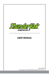
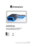
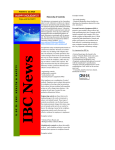
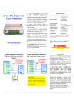
WARRANT Y AND LIMITS OF LIABILIT Y
Vulcain Inc. warrants to the original purchaser that its product and the component parts
thereof will be free from defects in workmanship and materials for a period of five years from
the date of purchase. Without any charge and at its option, Vulcain will repair or replace
defective products or components upon their delivery to its Repair and Service Department.
This warranty does not apply in the event of misuse or abuse of the product, or as a result of
unauthorized alterations or repairs. Vulcain shall not be liable for any consequential damages,
including and without limitation, damages resulting from loss of use.
Every precaution for accuracy has been taken in the preparation of this manual. However,
Vulcain neither assumes responsibility for any omissions or errors that may appear, nor liability for any damages that may result from the use of the products in accordance with the information contained in this manual.
To obtain warranty service, return the product, along with a complete description of the
defect, transportation prepaid. Vulcain assumes no risk for damage in transit. Following
warranty repair, the product will be returned to the buyer, transportation prepaid.
Technical Support Line:
1-800-563-2967
Before returning a product for warranty service,
please contact Vulcain’s Technical Support
Department.
Warranty Registration
To validate the warranty, this registration form must be completed in full and sent to
Vulcain within 90 days of the date of purchase. Fax it to Vulcain at 1 888 967-9938.
Customer name: _________________________________________________________________________
Address: __________________________________________________________________________________
City: ____________________________________________________ State/Province: _____________
Location of the installation: _______________________________________________________________
Serial No.: ________________________________________________________________________________
BEFORE RETURNING ANY INSTRUMENT, PLEASE CONTACT
US TO OBTAIN A RETURN OF MATERIAL AUTHORIZATION
NUMBER.
Vulcain Alarm Inc. All Rights Reserved
1
DR0013.06 502517 Juillet 2005
TABLE OF CONTENTS
WARRANT Y ...................................................................................................1
UNPACKING..................................................................................................3
DESCRIPTION ..............................................................................................3
INSTALLATION GUIDELINES........................................................................3
SURFACE-MOUNT INSTALLATION................................................................4
DUCT-T YPE INSTALLATION .........................................................................5
DUCT-MOUNT INSTALLATION DETAILS ......................................................6
USER INTERFACE .........................................................................................6
SPECIFICATIONS..........................................................................................7
PERIODIC INSPECTIONS AND CALIBRATION.............................................7
CALIBRATION MENU....................................................................................8
ELECTRICAL WIRING ...................................................................................9
4-20 mA LOOP CONFIGURATION ..............................................................10
4-20 MA CURRENT SOURCING OUTPUT CONFIGURATION..............................10
4-20 MA OUTPUT LOOP-POWERED OPERATION (FACTORY SETTING) .............10
VDC OUTPUT..............................................................................................12
0-5 VOLT OUTPUT.........................................................................................12
0-10 VOLTS OUTPUT .....................................................................................12
CALIBRATION PROCEDURE ...........................................................................13
DR0013.06 502517 Juillet 2005
2
Vulcain Alarm Inc. All Rights Reserved
UNPACKING
Open the package and remove the equipment and components. Make sure that
you have all the items described on the order form or packing slip.
DESCRIPTION
The 90DM3A is an infrared CO2 Carbon Dioxyde Gas Monitor. A 4-20 mA, 0-10 Vdc
or 0-5 Vdc output may be configured on-site. The monitor permits a reading
on a 0-2000 PPM range. Optional ranges at 0-1% or 5% Vol. are also available.
INSTALLATION GUIDELINES
Make sure to locate the monitor and sensing assembly(ies) in an area
easily accessible to a technician.
Avoid any location where the monitor could be subject to vibrations.
Avoid any location close to noisy equipment.
Avoid any location where temperature changes occur rapidly.
Verify all the requirements and existing regulations which may affect
the choice of location.
For the DT Duct-Type housing, installation is recommended on
a straight duct at least 3 feet (1 m) away from any curve.
Vulcain Alarm Inc. All Rights Reserved
3
DR0013.06 502517 Juillet 2005
SURFACE-MOUNT INSTALLATION
The recommended height for installation is 5 feet (1.5 m) from the floor for CO2
monitoring in offices or similar applications related to indoor air quality. For applications such as CO2 cylinder warehouses where health hazards are an issue, the
recommended height for installation is 1 foot (30 cm) from the floor.
Pull to open
Electric Box
DR0013.06 502517 Juillet 2005
4
Vulcain Alarm Inc. All Rights Reserved
DUCT-T YPE INSTALLATION
The 90DM3A may be duct-mounted. It will operate most effectively when the airspeed is between 500 and 4,000 ft/minute (2.5 to 20.3 m/sec), and it may be
installed to monitor incoming fresh air or outgoing exhausted air. Make sure to
verify all the requirements and existing regulations that may affect the choice of
its location. In order to optimize its operation we recommend installation on a
straight section of duct 3 feet (1 m) away from any curved ductwork.
1. Drill 3 cm openings for the sampling tubes.
2. Insert the sampling tube with its lateral air holes in the appropriate opening, orienting the air holes ( FLOW indication) to face the airflow.
3. Knock out the rear hole of the octogonal box and place the box on the plastic
plate. The box mounting holes must be vertically oriented. Mount the box with
two #8 metal screws.
4. Install the electric wire in the octogonal box.
5. Assemble the metallic mounting plate and the plastic base on the octogonal box
with two 1/2" 8/32 sheet-metal screws.
6. Install the rubber gasket to seal the middle opening.
7. Connect the power and the outputs as shown in the ELECTRICAL WIRING diagram.
8. Before mounting the cover of the sampling unit box, start the ventilation feeding fan and check if there is any air leakage. If necessary, seal with air plugs.
9. Press fit the 90DM3 onto the plastic base.
To convert from CFM to velocity (ft/minute), divide the flow by the area.
Example: In a 2 ft x 4 ft duct, where the area is 8 ft2 with a CFM of 30,000,
the air velocity will be 30,000 ft3/minute/(8 ft2) = 3,750 ft/minute
Vulcain Alarm Inc. All Rights Reserved
5
DR0013.06 502517 Juillet 2005
DUCT-MOUNT INSTALLATION DETAILS
USER INTERFACE
When the unit is powered ON, the display indicates the type
of unit and the revision.
For a very short time, the sensor sends information to the
display.
The type of gas and the word Warm-Up are displayed.
During normal operation, the display shows a “+” and an “X”
alternating to indicate the CPU is running, followed by the
transmitter’s address and type of gas. The gas concentration
read is indicated on the second line.
DR0013.06 502517 Juillet 2005
6
Vulcain Alarm Inc. All Rights Reserved
SPECIFICATIONS
Power Requirement:
17-27 Vac or 24-38 Vdc, 200 mA
Gas Detected:
CO2
Detection Range:
0-2000 PPM, 0-1% OR 0-5%
Accuracy:
± 40 ppm + 3% reading
Response Time:
<60 sec. (for 90% step change)
Sensor Life Expectancy:
> 10 years
Operating Temperature Range:
32°F to 100°F (0°C to 40°C)
Operating Humidity Range:
0% - 95% RH, Non-Condensing
Dimensions:
5.25 in (H) x 3.5 in ( W ) x 2.0 in (D)
(11.5 cm x 7.5 cm x 4.4 cm)
Weight:
SM: 0.55 lbs (0.20 kg)
DT: 0.66 lbs (0.30 kg)
Warranty:
5 year limited warranty
Optional Outputs:
1: 4-20 mA, 0-5 Vdc or 0-10 Vdc
2: 1 SPDT Relay
Relay Output Rating:
5A, 30 Vdc or 250 Vac (resistive load)
3: Display
LCD
PERIODIC INSPECTIONS AND CALIBRATION
This unit requires calibration. The calibration frequency will be a function of the
operating conditions, including operating under extreme temperatures, exposure
to contaminants or gas concentrations. A calibration inspection must be included
as part of a routine maintenance to ensure proper operation of the gas detection
unit.
If unit span or zero cannot be adjusted, the sensor may be
approaching its end-of-life and must be replaced.
Vulcain Alarm Inc. All Rights Reserved
7
DR0013.06 502517 Juillet 2005
CALIBRATION MENU
User Password to enter the Menu.
Scale configuration field.
Adjust the maximum scale concentration
for the transmitter.
Alarm setting field.
Adjusting Alarm level.
4mA setting field.
4mA adjusting field.
20mA setting field.
20mA adjusting field.
Zero setting field.
Activate the zero calibration using nitrogen.
* Zero * calibration is underway.
Calibration with the Span gas.
Adjust the Span gas value that will be used.
Accept the Span value and validate.
Span is underway.
Resets the unit.
Acknowledge if you want to reset.
To quit from the menu program.
The unit reinitializes itself once quitting the
Programming Menu.
DR0013.06 502517 Juillet 2005
8
Vulcain Alarm Inc. All Rights Reserved
ELECTRICAL WIRING
A wiring info sticker is pasted on the unit to simplify installation, however the electrical connections must be made according to the following information.
Outputs 4-20 mA,
0-5 Vdc or 0-10 Vdc:
Output J5. See details in Table 1
Power: Input J4
17 to 27 Vac, 24 to 38
Vdc, 200 mA
If the 4-20mA output is
present and configurated
in active mode, a local
power supply is required:
17 to 27 Vac,
24 to 38 Vdc,
200 mA
Relay Output
(optional): J2
5 A, 30 Vdc or 250 Vac
(resistive load)
N/C C N/O
Red LED:
Indication for calibration
when there is no display
Enter Key:
Validation Key
Scroll Key:
Browsing key
in menu mode
Vulcain Alarm Inc. All Rights Reserved
9
DR0013.06 502517 Juillet 2005
4-20 mA LOOP CONFIGURATION
4-20 mA CURRENT SOURCING OUTPUT CONFIGURATION
The transmitter supplies the loop current. The maximum impedance supported by
the loop is 400 ohms. Set jumpers on S1 at 1-2, 3-4 and 5-6.
WARNING
A dedicated power supply must be used with each unit. Considerable
damage may occur if this condition is not strictly followed.
4-20 mA OUTPUT LOOP-POWERED OPERATION
(Factory Setting )
The 4-20 mA output is factory set for loop-powered operation and requires a power
source of 12 Vdc to 30 Vdc. The overall impedance depends on the voltage supplied at
the 4-20 mA loop. Set jumpers on S1 at 2-3, 4-5 and 6-7 for this type of configuration.
Table 1
Permitted Impedance in the 4-20 mA Loop
Voltage Source Applied
Total Impedance
12 Vdc
16 Vdc
20 Vdc
24 Vdc
30 Vdc
400 Ohms
600 Ohms
800 Ohms
1000 Ohms
1300 Ohms
DR0013.06 502517 Juillet 2005
10
Vulcain Alarm Inc. All Rights Reserved
3-Wire Configuration
4-Wire Configuration
+
Vulcain Alarm Inc. All Rights Reserved
-
11
DR0013.06 502517 Juillet 2005
VDC OUTPUT
0-5 VOLT OUTPUT
The transmitter sends a voltage signal proportional to the gas concentration read
on the total detection scale. To configure this mode, take away the jumpers on S1.
Insert a jumper on position 5-6 of S1 and one jumper on J12. Insert the last
jumper on pin 7 of S1 for further use.
0-10 VOLTS OUTPUT
The transmitter sends a voltage signal proportional to the gas concentration read
on the total detection scale. To configure this mode, take away the jumpers on S1.
Insert a jumper on position 5-6 of S1, a second jumper on J12, and a third jumper
on J13.
WARNING
If several units are powered with the same transformer, the Vdc
outputs cannot share a common ground. Most DDC systems
share common ground, therefore, separate transformers must be
used for each unit, including the DDC. Do not attempt to connect any power sources to the Vdc outputs. The Vdc output must
not be grounded to earth.
Significant damage may occur if these recommendations are not followed.
DR0013.06 502517 Juillet 2005
12
Vulcain Alarm Inc. All Rights Reserved