1
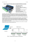
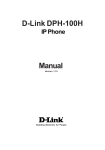
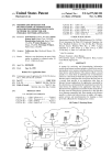
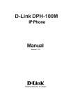
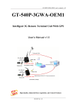
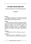
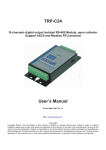
KTA-323 mini PLC
•
•
•
•
•
•
•
•
•
•
•
•
•
8 Relays with 5 A, 250 VAC rated contacts
4 Optically isolated digital inputs up to 30 VDC
DIN rail mountable
3 Analog inputs, 0 to 5 V or 0 to 20 mA jumper
selectable
On board 10/100baseTX Ethernet with globally
unique MAC address and DHCP
Power indicator, comms transmit and receive,
and relay status LED's
All enclosed in professional looking plastic case
Arduino Compatible – can be re-programed with
the Arduino IDE
Accepts XBee form factor expansion boards
FTDI232 based USB virtual serial interface
RS-485 serial interface
Can be used as a USB to RS-485 converter
Multiple units can be connected in an RS-485
bus
The KTA-323 is a USB, RS-485, or Ethernet controlled IO module for interfacing PC's to real world applications,
such as controlling lights and sprinkler systems, reading sensors and monitoring switches and other digital signals.
The controller ships programmed as an Arduino with a custom sketch loaded that listens for commands on the
serial ports (USB or RS-485) and responds by switching relays or returning the state of inputs. Additionally, the
KTA-323 operates as a web server on Ethernet. The custom sketch serves out a configuration page that can be
used to change the state of relays, and view all current I/O. The sketch is available on the Ocean Controls website
as an example of Arduino programming for the controller.
The custom sketch speaks a simple ASCII protocol that allows control from Windows/Mac/Linux using either USB
virtual serial drivers or RS-485. The controller acts as a USB to RS-485 converter, so multiple devices can be
connected to one RS-485 bus, allowing control of many devices from one USB port. The web server operates on
port 80, servicing web page requests on HTTP.
Figure 1 - Connecting multiple controllers with a RS485 network
The controller is based on the hardware of the Arduino physical computing controllers. It can be programmed as a
stand-alone controller using the free, open source Arduino environment. Internally, the KTA-323 is equivalent to an
Arduino Duemelanouve fitted with the Arduino Ethernet Shield (and a unique MAC address).
29 Oct 2015
www.oceancontrols.com.au
1 of 15
KTA-323 mini PLC
Connections:
Table 1 - Connections
Label
Description
Label
Description
Dx
Opto-Isolated Digital Input x
5VO
5V Output for Sensors
COM
Opto-Isolated Common
V+
Power Supply Positive Input
ANx
Analog Input x
GND
Ground
D+
RS485 Data+
USB
USB B-type connection to PC
D-
RS485 Data-
NO
Relay Normally Open Contact
ETHERNET
10/100baseTx Ethernet
C
Relay Common Contact
Specifications:
Power Supply V+ and COM:
8 to 32V DC
~3.1W + XBee peripheral + external 5V drain
Analog Inputs:
0 to 5 V: ~500 kΩ effective resistance with no jumper installed
0 to 20 mA: 250 Ω effective resistance with jumper installed
Opto-Isolated Input:
0 to 30 V, ~1 kΩ effective resistance
≤2.5 VDC activation threshold
3750VRMS isolation.
Relay Outputs:
SPST relays rated to 5 A (resistive).
250 VAC / 30 VDC
5 V Auxiliary Supply:
300 mA (less any XBee peripheral)
3.3V Auxillary Supply (for XBee):
50mA
Jumper Settings:
The Analog inputs of the KTA-323 can be set for 0 to 5 VDC or 0 to 20 mA operation. Opening the case and
inserting jumper shunts in the positions J1, J2 or J3 will set the associated analog inputs to 0 to 20 mA operation.
Removing the shunts will set the analog inputs to 0 to 5 VDC operation.
When the jumper labeled AUTO is installed the board will reset each time a serial connection is made to the USB
serial port. This should only be installed when reprogramming via the Arduino Environment, or the device will reset
each time a serial connection is made to the unit.
Push Buttons:
Two mechanical push buttons are also provided on the board. Pressing the RESET BUTTON manually resets the
microcontroller. This can be used to reprogram via the Arduino IDE; for a small period after reset the
microcontroller will be listening on the serial port for a new firmware upload.
29 Oct 2015
www.oceancontrols.com.au
2 of 15
KTA-323 mini PLC
The IP RESET button returns the Ethernet to the default IP settings if it is held down while the microcontroller
resets (either by power cycling or pressing the RESET BUTTON. The Custom Arduino sketch shows how this is
done.
Using the Controller:
The controller requires 8 to 32V DC, connected to V+ and COM. This can come from a plug-pack, bench top power
supply or battery. The controller has screw terminals for the connection of power. Plug-pack power supplies often
come with a plug on the end of the lead. The plug can be cut off and bare wires exposed for the screw terminals on
the controller.
Connect the power supply positive to the V+ terminal and negative to the COM terminal next to it. The POWER
LED should light. A diode protects the controller and prevents it from operating with power connected in reverse
polarity. If the LED does not light, ensure your supply is delivering sufficient voltage and is connected correctly.
Connect Ethernet via the RJ45 plug. The KTA-323 by default uses DHCP to retrieve a vacant IP address from your
network. This IP address is printed out of the USB socket. Holding down the IP ADDR RESET button on the board
will force the controller to use 192.168.1.100
For serial control, connect the KTA-323 to a computer using a USB A male to USB B male cable. When the power
is turned on your computer may prompt you to install drivers. The drivers required are the FTDI Virtual Serial
(COM) Port Drivers the latest versions for all systems are available from http://www.ftdichip.com/Drivers/VCP.htm
Communicating with the Controller:
The Address and Baud Rate of the unit can be set and are stored in the controller’s memory. By default the
controller is listening for serial data at 9600 baud, and has address 00. The controller will always use 1 Stop Bit, 8
Data Bits and No Parity.
The commands the controller uses are in the form:
@AA CC X<CR>
The @ symbol is used to define the start of a command.
AA is the address of the unit from 00 to 99.
CC is a two letter command used to determine the command type.
X is a one or more characters which determines the parameter for the command.
<CR> is the carriage return character. This is ASCII character 13, or 0x0d.
Each time a valid command is received the unit will respond with #AA followed by any values that are requested
from the unit.
Note that 00 is the Wildcard Address. All controllers respond to address 00 regardless of what their address has
been set to. If a command has 00 as the address, all devices on the bus will respond as if they have been
individually addressed.
29 Oct 2015
www.oceancontrols.com.au
3 of 15
KTA-323 mini PLC
Table 2 - Command set
Letter
Command
Parameters
ON
Turn Relay On
1-8: Turn Relay 1-8 On Individually
0: Turn All Relays On at Once
OF
Turn Relay Off
1-8: Turn Relay 1-8 Off Individually
0: Turn All Relays Off at Once
WR
Write to all Relays at
once
The parameter is a number which determines which of the relays
should be turned on or off.
TR
Turn Relay on for Set
Time
2 parameters, First is 1-8: Relay Number, Second 001-255: Time in
tenths of seconds to turn ON for
KA
Keep Alive
0: Turn Off Keep Alive
1-255: Time in Seconds
RS
Status of Relays
1-8: Returns Status of Relays 1-8 Individually
0: Returns Status of All Relays
IS
Status of Inputs
1-4: Returns Status of Inputs 1-4 Individually
0: Returns Status of All Inputs
AI
Read Analog Input
1-3: Read Value of Analog Input 1, 2 or 3
0: Returns Value of All Analog Inputs
SS
System Status
Must be 0, Returns status of all Relays, Analog and Digital Inputs
SA
Set Address
01-99: Sets the Address of the unit in Memory
SB
Set Baud Rate
1-10: Sets the Baud Rate
1: 1200 baud
6: 19200 baud
2: 2400 baud
7: 28800 baud
3: 4800 baud
8: 38400 baud
4: 9600 baud (default)
9: 57600 baud
5: 14400 baud
10: 115200 baud
ON: Relay On Command
This command is used to turn a single relay on. E.g.: @44 ON 1 will turn relay 1 on for the unit with address 44. It
can also be used to turn all the relays on, this occurs when the parameter value is 0.
OF: Relay Off Command
Similar to the on command this command will turn relays off in the same manner. E.g.: @44 OF 1 will turn relay 1
off for the unit with address 44, @44 OF 0 will turn all relays off.
WR: Write Relays Command
The write relays command is used when more than one relay is to be turned on or off at once. The parameter is a
decimal number which, in binary, represents the on and off status of the 8 relays. The least significant bit of this
value controls relay 1. The most significant bit of the parameter value controls relay 8. A set bit (1) turns the relay
on, a cleared bit (0) turns the relay off. Example: To turn relays 1, 2 and 6 on (and others off) the binary value
required is 00100011. In decimal this is 35. (2^(1-1) + 2^(2-1) + 2^(6-1) = 35). To issue this to a controller with
address 44, the required command is @44 WR 35
29 Oct 2015
www.oceancontrols.com.au
4 of 15
KTA-323 mini PLC
TR: Timed Relay Command (Software v1.1 and Later)
The timed relay command is used to turn a single relay on for a set period of time, after which the relay
automatically turns off. Two parameters are needed, separated by a space, the first is the relay number (1-8) and
the second is the time to turn the relay on for in tenths of seconds (001-255) the second parameter must have 3
digits. E.g.: @44 TR 1 050 will turn relay 1 on for 5 seconds.
KA: Keep Alive Command (Software v1.2 and Later)
This command is used as a watchdog timer. If the parameter is 0 the watchdog is turned off. If the parameters is
between 1 and 255 then if that time in seconds has elapsed without the unit receiving another Keep Alive command
then all the relays will turn off. This is used for a fail safe to ensure if the host software can no longer communicate
with the KTA-223 then the relays turn off.
IS: Input Status Command
This command will return the status of the inputs. If the parameter is between 1 and 4 then the controller will return
a 0 or 1 corresponding to that input. E.g.: @44 IS 1 will return #44 1 if the input is on, or #44 0 if the input is off.
If the parameter is 0 then the unit will respond with the status of all the inputs, in similar form as the Write Relays
command. E.g.: If inputs 1 and 2 for the unit are on then @44 IS 0 will return #44 3. 3 is 0011 in binary, and each
bit represents each input from 4 down to 1.
RS: Relay Status Command:
Much the same as the input status command, this command will return the status of the relays. If the parameter is
between 1 and 8 then the unit will return with a 0 or 1 corresponding to that relay. E.g.: @44 RS 1 will return #44 1
if the relay is on, or #44 0 if the relay is off.
If the parameter to this command is 0 then the unit will respond the same way as the input status command, but
return the status of the relays.
AI: Analog Input Command
The analog input command will read the status of the analog input defined by the parameter and return it as a value
between 0 and 1023. E.g.: @44 AI 1 will return #44 512 if the analog input is reading 50%.
SS: System Status (Software v1.1 and Later)
The system status will requires a parameter of 0 and returns the status of all relays and inputs, 5 values each
separated by a space. The first value returned is the same as is returned for an RS 0 command, the second value
returned is the same as is returned for an IS 0 command and the last 3 values returned are the same as returned
from and AI 0 command.
SA: Set Address
Addresses are valid from 01-99. A unit will only respond if its address in memory is the same as that of the
command sent, or if the address of the command sent is 00. The address is saved to non-volatile memory inside
the controller, meaning it will be preserved even after power is disconnect from the controller.
SB: Set Baud
Parameters from 1 to 10 are valid, corresponding to values shown in Table 3.
1: 1200 baud
Table 3 - Baud rate selection
6: 19200 baud
2: 2400 baud
7: 28800 baud
3: 4800 baud
8: 38400 baud
4: 9600 baud (default)
9: 57600 baud
5: 14400 baud
10: 115200 baud
The baud rate is saved to non-volatile memory inside the controller, meaning it will be preserved even after power
is disconnect from the controller.
29 Oct 2015
www.oceancontrols.com.au
5 of 15
KTA-323 mini PLC
Web Server:
Figure 2 - Served Web Pages
The KTA-323 custom Arduino sketch contains code for serving out a web page as well as a mobile optimised
version. The web server listens for HTTP requests on port 80, and serves out the configuration page when
requested.
You can access one of four web pages (note that the http:// is optional in most browsers):
http://<ip address>/demo
Brings up a list of all of the IO on the KTA-323 with current statuses.
http://<ip address>/demo/form
29 Oct 2015
www.oceancontrols.com.au
6 of 15
KTA-323 mini PLC
Brings up a web form that shows the status of all of the IO on the KTA-323, and also allows the user to change the
state of the relays.
http://<ip address>/demo/mobile
Brings up a list of the 8 Relays in a format optimised for small screens (i.e on a mobile phone). The user can check
the status, and change, the state of the relays.
http://<ip address>/demo/mobileI
Brings up a list of the digital and analog inputs in a mobile optimised format.
These two mobile websites are linked to each other with the button at the end of the page.
The IP settings are set automatically when plugged onto your local network. To find out the IP address of the KTA323, listen to the serial port using a terminal program. On power up, the IP address is printed.
Example:
Using Arduino IDE built in hyperterminal (tools-> serial monitor):
The IP address can be forced to default (192.168.1.100) by holding down the IP ADDR RESET button as power is
applied to the KTA-323.
29 Oct 2015
www.oceancontrols.com.au
7 of 15
KTA-323 mini PLC
Test Utility:
Figure 3 - Test Utility
Ocean Controls provides a test utility for the KTA-323. This program – and its source code - is available as a free
download from the Ocean Controls website: http://oceancontrols.com.au. The source code is written in Visual Basic
Express 2010 which is available free from Microsoft.
If the Address of the unit you wish to control is known put it in the “Address” text box, if not, use 0 for the address
and any unit will respond.
Enter the COM Port number in the “Port” text box, if this is not known it can be found by clicking “list ports”.
Once the device is communicating, Relays can be turned on or off by clicking the buttons in the Relays group and
the status of the Digital and Analog Inputs are shown in their relevant groups.
A web browser is also provided. Navigate to the URL of the KTA-323 using the text box, and the configuration page
will be shown.
Using the Controller as an Arduino:
The KTA-323, as supplied, is an Arduino compatible board with Arduino bootloader and a custom sketch loaded
that responds to the serial commands, and serves out the webpage listed above. The source code of this is
available from the Ocean Controls website and can be modified in the Arduino environment to suit your purpose.
The Arduino programming environment can be downloaded for Windows, Mac OS X and Linux from
http://www.arduino.cc/
When using the KTA-323 with the Arduino Environment select “Arduino Duemilenove w/ ATmega328” from the
“Tools->Board” menu, and install the “AUTO” jumper on the PCB for ease of programming.
The Ethernet is based on the hardware of the Arduino Ethernet Shield, and is fully compatible with the Ethernet
library. Electrically, the KTA-323 can be thought of as an Arduino Duemilenove fitted with the Ethernet shield. An
on board EEPROM chip also holds a globally unique MAC address that gets loaded into the Ethernet controller on
startup.
The EEPROM chip is accessed via SPI and shares an inverted SS (Slave Select) line with the Ethernet controller.
This pin is therefore either signaled low to access the Ethernet controller, or signaled high to signal to the EEPROM
chip. The custom sketch shows how the MAC address is retrieved, and then loaded into the Ethernet controller.
The RS-485 transceiver is connected in parallel with the FTDI USB to Serial converter and ATMega328 UART pins.
This transceiver allows half-duplex serial communication over 2 or 3 wires. The transceiver requires a TX Control
signal to enable the transmit or receive line driver. When transmitting, the TX Control line must be asserted (driven
high). To receive, the line must be left low.
29 Oct 2015
www.oceancontrols.com.au
8 of 15
KTA-323 mini PLC
The board handles all 5V to 3.3V level shifting required. Note that the expansion module “takes over” the Rx (D0)
bus, meaning that the controller will not be able to receive data from RS-485 or USB while a module is fitted.
The FT232RL USB to Serial converter provides a TXEN signal for RS-485 Transceivers. When data is received
from the USB port by the FT232RL, it asserts the TX Control line, putting the RS-485 transceiver in Transmit mode.
The serial data is then transmitted to the ATMega328 and onto the RS-485 network.
Using the RS-485 transceiver from custom Arduino code requires that your code drive the TX Control line high at
the beginning of data transmission and returns it low at the end of the transmission. The TX Control line is
connected to Digital 19. The Ocean Controls sketch provides an example of how to do this.
The hardware has been designed to accept XBee form factor expansion modules. When plugged in, these modules
will be provided with 3.3V from an on-board regulator (up to 50mA). The Arduino Tx (D1) and Rx (D0) signals tie
directly into the XBee DIN (pin 3) and DOUT (pin 2) signals, allowing TTL UART communications between the
microcontroller and expansion module.
D1 → DIN
DOUT → D0
Table 4 - Arduino, KTA-323, and AVR pin mapping
KTA-323 IO
Arduino Pin
AVR Port.Pin
KTA-323 IO
Arduino Pin
AVR Port.Pin
Relay 1
Digital 2
PORTD.2
Analog In 1
Analog 6
ADC6
Relay 2
Digital 3
PORTD.3
Analog In 2
Analog 7
ADC7
Relay 3
Digital 4
PORTD.4
Analog In 3
Analog 0
PORTC.0
Relay 4
Digital 5
PORTD.5
RX Data
Digital 0
PORTD.0
Relay 5
Digital 6
PORTD.6
TX Data
Digital 1
PORTD.1
Relay 6
Digital 7
PORTD.7
RS-485 TX
Control
Digital 19 /
Analog 5
PORTC.5
Relay 7
Digital 8
PORTB.0
SPI SS
Digital 10
PORTB.2
Relay 8
Digital 9
PORTB.1
SPI MOSI
Digital 11
PORTB.3
Opto-In 1
Digital 15 / Analog 1
PORTC.1
SPI MISO
Digital 12
PORTB.4
Opto-In 2
Digital 16 / Analog 2
PORTC.2
SPI SCK
Digital 13
PORTB.5
Opto-In 3
Digital 17 / Analog 3
PORTC.3
Opto-In 4
Digital 18 / Analog 4
PORTC.4
29 Oct 2015
www.oceancontrols.com.au
9 of 15
KTA-323 mini PLC
KTA-323 Wiring Examples: Inputs
The opto-isolated inputs allow for a range of connection possibilities. They are bi-directional, meaning they activate
if current is passed in either direction through their inputs. One side of all of the opto's are tied together to the COM
terminal. The figures below show how to interface a dry-contact switch, NPN, and PNP-type sensor.
Figure 4 - Wiring a dry contact switch
Figure 5 - Wiring an NPN-type sensor
Figure 6 - Wiring a PNP-type sensor
29 Oct 2015
www.oceancontrols.com.au
10 of 15
KTA-323 mini PLC
Analog inputs can be wired for 0 to 5 V or 0 to 20 mA signals, depending on the position of the input jumper inside
the unit. A regulated 5 VDC output is provided for the convenience of wiring analog sensors like potentiometers.
Figure 7 - Wiring a potentiometer
Figure 8 - Wiring a 4 to 20 mA, loop-powered sensor
Wiring Examples: Outputs
The relay outputs on the KTA-323 can be wired to DC or AC loads.
Figure 9 - Wiring a basic DC load
Inductive loads at high currents cause large voltage spikes when turned on or off, and this can disrupt sensitive
electronics. For large inductive loads, a snubber is recommended. A DC load can be bypassed with a circulation
29 Oct 2015
www.oceancontrols.com.au
11 of 15
KTA-323 mini PLC
diode. An AC load requires an RC snubber across the relay contacts or load. Ensure that diodes, resistors and
capacitors used for snubbers are correctly rated for the load and voltage being switched.
Figure 10 - Wiring Snubber Circuits
29 Oct 2015
www.oceancontrols.com.au
12 of 15
KTA-323 mini PLC
Hardware Revision History:
KTA-323v1:
Prototype
KTA-323v2:
Initial Release
Software Revision History:
The KTA-323 comes pre-programmed as an Arduino with a sketch loaded. The sketch can be upgraded using the
Arduino IDE.
Software v1.0: Initial Release.
Software v1.1: Added a mobile optimised website.
Licensing:
The KTA-323 is derived from the Arduino Deumilanove and the schematics and CAD files are available under
Creative Commons Attribution Share-Alike licenses. Contact [email protected] for more information.
29 Oct 2015
www.oceancontrols.com.au
13 of 15
KTA-323 mini PLC
29 Oct 2015
www.oceancontrols.com.au
14 of 15
KTA-323 mini PLC
29 Oct 2015
www.oceancontrols.com.au
15 of 15