Download Ocean Controls KTA-223 Arduino Compatible USB Relay
Transcript
Ocean Controls - KTA-223
12/11/2009
Ocean Controls KTA-223 Arduino Compatible USB Relay Controller
•
•
•
•
•
•
•
•
•
•
•
•
8 Relay Outputs 5A 250VAC
4 Opto-Isolated Inputs 5-30VDC
3 Analog Inputs (10 bit)
Connections via Pluggable Screw Terminals
0-5V or 0-20mA Analog Inputs, Jumper Selectable
5A Relay Switching
Power Indicator LED
All enclosed in Professional looking plastic case
Arduino Compatible
Accepts Arduino Shields (Ethernet / XBEE)
USB Virtual COM or RS485 Input
Easily connect multiple units far apart by RS485
The KTA-223 is a USB or RS485 controlled IO module for interfacing PCs to real world applications, such as
controlling lights and sprinkler systems, reading sensors and monitoring switches and other digital signals. The
Relays are capable of switching up to 5A at 250VAC, 10A at 120VAC and 10A at 24VDC but the PCB tracks will
only handle up to about 5A. A simple ASCII protocol allows control from Windows/Mac/Linux using either USB
Virtual COM drivers or RS485. Additionally, multiple devices can be connected to one RS485 bus, allowing control
of many devices from one USB port.
The controller is based on the hardware of the Arduino physical computing controllers. It can be programmed as a
stand-alone controller using the free, open source Arduino environment. Internally, the controller is “shieldcompatible”, allowing the use of many extension boards designed for the Arduino Deumilanove. As shipped the
controller is loaded with a sketch that receives simple commands over the USB or RS485 serial port and switches
relays or responds with the status of inputs. This sketch is available on the Ocean Controls website as an example
of Arduino programming for the controller.
Multiple controllers can be connected to one or more PCs in an RS485 network. Each controller can be assigned
an address and will respond to commands addressed to them.
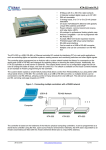
Figure 1 - Connecting multiple controllers with a RS485 network
1 of 8
Ocean Controls - KTA-223
12/11/2009
Connections
Table 1 - Connections
Label
Description
Label
Description
+
Opto-Isolated Input Positive
5VO
5V Output for Sensors
-
Opto-Isolated Input Negative
V+
12V Power Supply Positive Input
ANx
Analog Input x
COM
Common Connection (Ground)
COM
Common Connection (Ground)
USB
USB B-type connection to PC
D+
RS485 Data+
NO
Relay Normally Open Contact
D-
RS485 Data-
C
Relay Common Contact
NC
Relay Normally Closed Contact
Specifications
Power Supply V+ and COM:
KTA-223: 9-16V DC (12V Nominal) ~200mA + External 5V drain
KTB-223: 18-32V DC (24V Nominal) ~200mA + External 5V drain
Analog Input ANx:
0-5V: ~500kΩ effective resistance with no jumper installed
0-20mA: ~250Ω effective resistance with jumper installed
Opto-Isolated Input: 0-30V, ~1kΩ effective resistance
Relay Outputs: SPDT relays rated to 5A (resistive). 250VAC / 30VDC
5V Auxiliary Supply 5V: 200mA
Jumper Settings
The Analog inputs of the KTA-223 can be set for 0-5V or 0-20mA operation. Opening the case and inserting jumper
shunts in the positions J1, J2 or J3 will set the associated analog inputs to 0-20mA operation. Removing the shunts
will set the analog inputs to 0-5V operation.
The Analog inputs are protected with 4.7kΩ inline resistors, this will protect the microcontroller from damage for
accidental input voltages up to 30V.
When the jumper labeled AUTO RESET is installed the board will reset each time a serial connection is made to
the USB COM port. This should only be installed when reprogramming via the Arduino Environment, or the device
will reset each time a serial connection is made to the unit.
Using the Controller
The controller requires 12VDC or 24VDC to operate, connected to V+ and COM. This can come from a plugpack, bench top power supply or battery. The controller has screw terminals for the connection of power. Plugpack power supplies often come with a plug on the end of the lead. The plug can be cut off and bare wires
exposed for the screw terminals on the controller.
Connect the power supply positive connects to the V+ terminal and negative to the COM terminal next to it. The
POWER LED should light. A diode protects the controller and prevents it from operating with power connected in
reverse polarity. If the LED does not light, ensure your supply is delivering sufficient voltage and is connected
correctly.
2 of 8
Ocean Controls - KTA-223
12/11/2009
Connect the controller to a computer using a USB A male to USB B male cable. When the power is turned on your
computer may prompt you to install drivers. The drivers required are the FTDI Virtual COM Port Drivers the latest
versions for all systems are available from http://www.ftdichip.com/Drivers/VCP.htm
Test Utility
The main window of the Windows test utility is shown here.
If the Address of the unit you wish to control is known put it in
the “Address” text box, if not, use 0 for the address and any unit
will respond.
Enter the COM Port number in the “Port” text box, if this is not
known it can be found in the device manager under ports. The
quickest way to run device manager is by clicking Start->Run
and then typing “devmgmt.msc”.
Once the device is communicating, Relays can be turned on or
off by clicking the buttons in the Relays group and the status of
the Digital and Analog Inputs are shown in their relevant groups.
The source code for this program is available from Ocean
Controls and is written in Visual Basic Express 2008 which is
available free from Microsoft.
Ocean Controls can also supply a similar example program with
source code for Visual Basic 6.
Figure 2 - Windows Test Utility
Communicating with the Controller
The Address and Baud Rate of the unit can be set and are stored in the controllerʼs memory. By default the
controller is listening for serial data at 9600 baud, and has address 00. The controller will always use 1 Stop Bit, 8
Data Bits and No Parity.
The commands the controller uses are in the form
@AA CC X<CR>
The @ symbol is used to define the start of a command.
AA is the address of the unit from 00 to 99.
CC is a two letter command used to determine the command type.
X is a one or more characters which determines the parameter for the command.
<CR> is the carriage return character. This is ASCII character 13, or 0x0d.
Each time a valid command is received the unit will respond with #AA followed by any values that are requested
from the unit.
Note that 00 is the Wildcard Address, if a command has 00 as the address, all devices will respond as if they have
been individually addressed.
3 of 8
Ocean Controls - KTA-223
Letter
Command
ON
Turn Relay On
12/11/2009
Table 2 - Command set
Parameters
1-8: Turn Relay 1-8 On Individually
0: Turn All Relays On at Once
OF
Turn Relay Off
1-8: Turn Relay 1-8 Off Individually
0: Turn All Relays Off at Once
WR
Write to all Relays at once
The parameter is a number which determines which of the
relays should be turned on or off.
RS
Status of Relays
1-8: Returns Status of Relays 1-8 Individually
0: Returns Status of All Relays
IS
Status of Inputs
1-4: Returns Status of Inputs 1-4 Individually
0: Returns Status of All Inputs
AI
Read Analog Input
1-3: Read Value of Analog Input 1, 2 or 3
0: Returns Value of All Analog Inputs
SA
Set Address
01-99: Sets the Address of the unit in Memory
SB
Set Baud Rate
1-10: Sets the Baud Rate
1: 1200 baud
6: 19200 baud
2: 2400 baud
7: 28800 baud
3: 4800 baud
8: 38400 baud
4: 9600 baud (default)
9: 57600 baud
5: 14400 baud
10: 115200 baud
ON: Relay On Command
This command is used to turn a single relay on. E.g.: @44 ON 1 will turn relay 1 on for the unit with address 44. It
can also be used to turn all the relays on, this occurs when the parameter value is 0.
OF: Relay Off Command
Similar to the on command this command will turn relays off in the same manner. E.g.: @44 OF 1 will turn relay 1
off for the unit with address 44, @44 OF 0 will turn all relays off.
WR: Write Relays Command
The write relays command is used when more than one relay is to be turned on or off at once. The parameter is a
decimal number which, in binary, represents the on and off status of the 8 relays. The least significant bit of this
value controls relay 1. The most significant bit of the parameter value controls relay 8. A set bit (1) turns the relay
on, a cleared bit (0) turns the relay off.
Example: To turn relays 1, 2 and 6 on (and others off) the binary value required is 00100011. In decimal this is 35.
(2^(1-1) + 2^(2-1) + 2^(6-1) = 35). To issue this to a controller with address 44, the required command is @44 WR
35
IS: Input Status Command
This command will return the status of the inputs. If the parameter is between 1 and 4 then the controller will return
a 0 or 1 corresponding to that input. E.g.: @44 IS 1 will return #44 1 if the input is on, or #44 0 if the input is off.
If the parameter is 0 then the unit will respond with the status of all the inputs, in similar form as the Write Relays
command. E.g.: If inputs 1 and 2 for the unit are on then @44 IS 0 will return #44 3. 3 is 0011 in binary, and each
bit represents each input from 4 down to 1.
4 of 8
Ocean Controls - KTA-223
12/11/2009
RS: Relay Status Command:
Much the same as the input status command, this command will return the status of the relays. If the parameter is
between 1 and 8 then the unit will return with a 0 or 1 corresponding to that relay. E.g.: @44 RS 1 will return #44 1
if the relay is on, or #44 0 if the relay is off.
If the parameter to this command is 0 then the unit will respond the same way as the input status command, but
return the status of the relays.
AI: Analog Input Command
The analog input command will read the status of the analog input defined by the parameter and return it as a value
between 0 and 1023. E.g.: @44 AI 1 will return #44 512 if the analog input is reading 50%.
SA: Set Address
Addresses are valid from 01-99. A unit will only respond if its address in memory is the same as that of the
command sent, or if the address of the command sent is 00. The address is saved to non-volatile memory inside
the controller, meaning it will be preserved even after power is disconnect from the controller.
SB: Set Baud
Parameters from 1 to 10 are valid, corresponding to values shown in Table 3.
1: 1200 baud
Table 3 - Baud rate selection
6: 19200 baud
2: 2400 baud
7: 28800 baud
3: 4800 baud
8: 38400 baud
4: 9600 baud (default)
9: 57600 baud
5: 14400 baud
10: 115200 baud
The baud rate is saved to non-volatile memory inside the controller, meaning it will be preserved even after power
is disconnect from the controller.
Using the Controller as an Arduino
The KTA-223, as supplied, is an Arduino compatible board with Arduino bootloader and a custom sketch loaded
that responds to the serial commands listed above. The source code of this is available from Ocean Controls and
can be modified in the Arduino environment to suit your purpose.
The Arduino programming environment can be downloaded for Windows, Mac OS X and Linux from
http://www.arduino.cc/
When using the KTA-223 with the Arduino Environment select “Arduino Duemilenove w/ ATmega328” from the
“Tools->Board” menu, and install the “AUTO RESET” jumper on the PCB for ease of programming.
The hardware has been designed to accept the Arduino compatible Shields. The cover may not be able to be
installed when using larger shields. Some shields may require removal or modification of the back panel to fit overhanging components (The Libelium XBee shield fits with XBee modules using chip antennae, but SMA antenna
connections conflict with the back panel)
The V1 controller PCB does not locate the 6-pin ICSP in the same position as the Arduino Deumillanove. Some
shields (notably the Libelium XBee shield) take 5V power, ground or other signals from the ICSP header. These
shields must be supplied power or signals from the standard Arduino header rows, or extended from the ICSP
connection on the controller the the shield.
The the Libelium XBee shield must be supplied with 5V power by connecting 5V on the shield to K6 Pin 2 and GND
on the shield to K6 Pin 6.
Space is provided on the PCB to install the SparkFun Real Time Clock module (SparkFun SKU: BOB-00099). The
intention is to allow the controller to operate in stand alone situations that require more timing flexibility than the
stock controller can provide. The PCB connects the RTC module SDA to Arduino Digital 12 and SCL to Arduino
Digital 13. Installing this unit may prevent proper operation of other modules or shield that rely on these pins (for
example, the Ethernet shield cannot be used with the RTC module.)
The RS485 transceiver is connected in parallel with the FTDI USB to Serial converter and ATMega328 UART pins.
This transceiver allows half-duplex serial communication over 2 or 3 wires. The transceiver requires a TX Control
5 of 8
Ocean Controls - KTA-223
12/11/2009
signal to enable the transmit or receive line driver. When transmitting, the TX Control line must be asserted (driven
high). To receive, the line must be left low.
The FT232RL USB to Serial converter provides a TXEN signal for RS485 Transceivers. When data is received
from the USB port by the FT232RL, it asserts the TX Control line, putting the RS485 transceiver in Transmit mode.
The serial data is then transmitted to the ATMega328 and onto the RS485 network.
Using the RS485 transceiver from custom Arduino code requires that your code drive the TX Control line high at the
beginning of data transmission and returns it low at the end of the transmission. The TX Control line is connected
to Digital 19. The Ocean Controls sketch provides an example of how to do this.
Table 4 shows the mapping of Arduino pins to the inputs and outputs of the controller.
KTA-223 IO
Table 4 - Arduino Pin Mapping
Arduino Pin
AVR Port.Pin
Relay 1
Digital 2
PORTD.2
Relay 2
Digital 3
PORTD.3
Relay 3
Digital 4
PORTD.4
Relay 4
Digital 5
PORTD.5
Relay 5
Digital 6
PORTD.6
Relay 6
Digital 7
PORTD.7
Relay 7
Digital 8
PORTB.0
Relay 8
Digital 9
PORTB.1
Opto-In 1
Digital 15 / Analog 1
PORTC.1
Opto-In 2
Digital 16 / Analog 2
PORTC.2
Opto-In 3
Digital 17 / Analog 3
PORTC.3
Opto-In 4
Digital 18 / Analog 4
PORTC.4
Analog In 1
Analog 6
ADC6
Analog In 2
Analog 7
ADC7
Analog In 3
Analog 0
PORTC.0
RX Data
Digital 0
PORTD.0
TX Data
Digital 1
PORTD.1
RS485 TX Control
Digital 19 / Analog 5
PORTC.5
Ethernet Shield
Digital 10
PORTB.2
Ethernet Shield
Digital 11
PORTB.3
Ethernet Shield / RTC
SDA
Digital 12
PORTB.4
Ethernet Shield / RTC
SCL
Digital 13
PORTB.5
6 of 8
Ocean Controls - KTA-223
12/11/2009
Wiring Examples: Inputs
The opto-isolated inputs allow for a range of connection possibilities. The figures below show the wiring for a drycontact switch, NPN and PNP-type sensor.
Figure 3 - Wiring a dry contact switch
Figure 4 - Wiring an NPN-type sensor
Figure 5 - Wiring a PNP-type sensor
Analog inputs can be wired for 0-5V or 0-20mA signals, depending on the position of the input jumper inside the
unit. A regulated 5V output is provided for the convenience of wiring analog sensors like potentiometers.
Figure 6 - Wiring a potentiometer
7 of 8
Ocean Controls - KTA-223
12/11/2009
Figure 7 - Wiring a 4-20mA, loop-powered sensor
Wiring Examples: Outputs
The relay outputs on the KTA-223 can be wired to DC or AC loads.
Figure 8 - Wiring a basic DC load
Inductive loads at high currents cause large voltage spikes when turned on or off, and this can disrupt sensitive
electronics. For large inductive loads, a snubber is recommended. A DC load can be bypassed with a circulation
diode. An AC load requires an RC snubber across the relay contacts. Ensure that diodes, resistors and capacitors
used for snubbers are correctly rated for the load and voltage being switched.
Errata
The V1 PCB requires a link to be installed from R8 (pad furthest from MAX48) to the via closest to MAX485 Pin 5.
This will have been installed by Ocean Controls on boards purchased through them or a distributor.
Selection Guide
Licensing
The KTA-223 is derived from the Arduino Deumilanove and the schematics and CAD files are available under
Creative Commons Attribution Share-Alike licenses. Contact [email protected] for more information.
8 of 8


