1
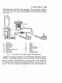
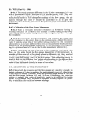
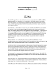
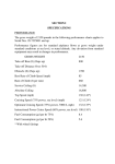
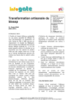
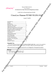
इंटरनेट
मानक
Disclosure to Promote the Right To Information
Whereas the Parliament of India has set out to provide a practical regime of right to
information for citizens to secure access to information under the control of public authorities,
in order to promote transparency and accountability in the working of every public authority,
and whereas the attached publication of the Bureau of Indian Standards is of particular interest
to the public, particularly disadvantaged communities and those engaged in the pursuit of
education and knowledge, the attached public safety standard is made available to promote the
timely dissemination of this information in an accurate manner to the public.
“जान1 का अ+धकार, जी1 का अ+धकार”
“प0रा1 को छोड न' 5 तरफ”
“The Right to Information, The Right to Live”
“Step Out From the Old to the New”
Mazdoor Kisan Shakti Sangathan
Jawaharlal Nehru
IS 7032-1 to 8 (1986): Physical methods of test for uncut
Indian jute, Mesta and Bimli [TXD 1: Physical Methods of
Tests]
“!ान $ एक न' भारत का +नम-ण”
Satyanarayan Gangaram Pitroda
“Invent a New India Using Knowledge”
“!ान एक ऐसा खजाना > जो कभी च0राया नहB जा सकता ह”
है”
ह
Bhartṛhari—Nītiśatakam
“Knowledge is such a treasure which cannot be stolen”
(Reaffirmed 2000)
IS : 7032 ( Parts 1 to 8 ) - 1986
Indian Standard
PHYSICAL METHODS OF TEST FOR
UNCUT INDIAN JUTE, MESTA AND BZMLZ
( First Revision )
Physical Methods of Test Sectional Committee,
TDC 1
Representing
Chairman
Technological
Cotton
( ICAR ), Bombay
DR V. SUNDARAM
Research
Laboratory
Members
DR V. G. MUNSHI ( Alternate to
Dr V. Sundaram )
Directorate of Marketing & Inspection ( Ministry
AGRICULTURAL MARKETING
of Agriculture ), Faridabad
ADVISER TO THE GOVERNMENTOF
INDIA
Directorate
General
of Supplies & Disposals
SHRI A. T. BASAK
( Inspection Wing ), New Delhi
SHRI D. K. NANDY ( Alternate )
Office of the Jute Commissioner,
Calcutta
SHRI B. N. BASU
Ltd,
Corporation
Petrochemicals
Indian
SHRI C. BHATTACHARYA
Vadodara
SHRI H. C. BHATIA ( Alternate )
GENERAI. MANAGER ( OPERATIONS ) The National Rayon Corporation Ltd, Bombay
SHRI D. S. NAD~ARNI ( Alternate )
Ministry of Defence ( R & D )
SHRI R. GHOSH
SHRI S. S. BAGGA ( Aliernafe )
Fibres
& Chemicals
Ltd,
Nirlon
Synthetic
DR V. G. KAMATH
Bombay
DR A. R. MUKHERJEE( Alternate )
The~~l~b~yArt Silk Mills Research Association,
SHRIMATI A. KAPLESH
SHRI M. R. PARANJAPE ( Alternate )
Ministry of Defence ( DGI )
SHRI M. K. MAM
SHRI P. C. BASU ( Alternate )
Intexa India, Bombay
DR B. R. MANJUNATHA
DR ( SHRIMATI ) G. R. PHALGUMANI Textiles Committee, Bombay
The
Bombay
Textile
Research
SHRI M. RADHAKRISHNAN
Bombay
SHRI A. V. RAVINDRANATHAN ( Alternate )
Association,
( Continued on page 2 )
@I Copyright 1987
BUREAU
OF INDIAN
STANDARDS
This publication
is protected
under the Zndian Copyright Act ( XIV of 1957 ) and
reproduction in whole are in part by any means except with written permission of the
publisher shall be deemed to be an infringement of copyright under the said Act.
IS : 7032 ( Parts 1 to 8 ) - 1986
( Continued from page 1 )
Members
Representing
SHRIMATI G. P. RANE
DR S. R. RANGANATHAN
Wool Research Association, Bombay
Indian Jute Industries’
Research
Association,
Calcutta
DR U. MUKHOPADHYAY ( Alternate )
NationalTextile
Corporation Limited, New Delhi
SHRI M. S. RATHORE
The South India Textile Research Association,
SHRI K. N. SESHAN
Coimbatore
The Raymond Woollen Mills Limited, Thane
DR G. S. SINGH
SHRI J. K. BANERJEE( Alternate )
Textile India Research Bureau, Bombay
SHRI C. SIVARAMAN
Central Silk Board, Bangalore
SHRI T. N. SONWALKAR
Office of the Textile Commissioner,
Bombay
DR T. V. K. SRIVASTAVA
SHRI S. RAVINDRAN ( Alternate >
Ahmedabad Textile Industry’s Research AssociaSHRI T. A. SLJBRAMANIAN
tion, Ahmadabad
M. Best Cotton Rope Manufacturing Co, Bombay
SHRI M. G. THANAWALA
Punjab State Hosiery and Knitwear Development
SHRI J. N. VOHRA
Corporation Ltd, Chandigarh
SHRI P. T. BANERJI ( Alternate )
Director General, BIS ( Ex-officio Member )
SHRI R. I. MIDHA,
Director ( Tex ) ( Secretary )
Physical
Methods
of Test for Jute Subcommittee,
TDC 1 : 3
Convener
DR U. MUKHOPADHYAY
Indian
Jute
Calcutta
Industries’
Research
Association,
Members
SHRI S. K. CHATTERJEE(
Alternate to
Dr U. Mukhopadhyay
)
Indian Jute Mills Association, Calcutta
SHRI G. M. BHANDARI
SHRI S. K. KARIWALA ( Alternate )
National
Jute Manufactures
Corporation
Ltd,
SHRI A. C. BISWAS
Calcutta
National Test House, Calcutta
SHRI A. GHOSH
Directorate of Jute Development
( Ministry of
DR K. CHAKRAVARTY
Agriculture ), Calcutta
SHRI N. C. HALDER ( Alternate )
Office of the Jute Commissioner,
Calcutta
SHRI D. K. DUTTA
Research
Laboratories
Technological
Jute
SHRI S. N. GHOSH
( ICAR ), Calcutta
SHRI N. K. SIL ( Alternate )
Eskaps ( India ) Private Limited, Calcutta
SHRI SEKHAR GUHA
Export Inspection Council of India, New Delhi
SHRI B. MAJUMDAR
SHRI P. K. GIRI ( Alternate >
The Jute Corporation of India Ltd, Calcutta
SHRI A. N. SANYAL
Ministry of Defence ( DGI )
DR R. K. SARKAR
Institute of Jute Technology, Calcutta
DR DEBANJAN SUR
SHRI S. C. ROY ( Alternate )
2
IS : 7032 ( Parts 1 to 8 ) - 1986
Indian Standard
PHYSICAL METHODS OF TEST FOR
UNCUT INDIAN JUTE, Ah%!%4 AND BZMLZ
(First Revision)
0. FOREWORD
0.1 This Indian Standard (Parts 1 to 8 ) ( First Revision ) was adopted by
the Indian Standards Institution on 27 June 1986, after the draft finalized
by the Physical Methods of Test Sectional Committee had been approved
by the Textile Division Council.
0.2 This standard consisting of nine parts ( Parts 1 to 9 ) was published
between 1973 and 1976 and covered methods of test for various characteristics of jute fibres. After the publication of IS : 271-1975 *Grading of
white, TOSSA and DAISEE uncut Indian jute ( second revision )‘, IS : 98461981 ‘Grading of uncut Indian MESTA’, and IS : 11596-1986 ‘Grading
of uncut Indian BIMLZ’ have been published. These standards have taken
into consideration the characteristics such as strength, lustre, colour,
density, fineness, root content and defects, etc, for grading of fibres. These
grading standards prescribe the ‘Hand and eye method’ for grading and
allot scores for different characteristics.
This standard ( Parts 1 to 8 )
has been revised to make it applicable to MESTA and BZMLZ fibres also.
The method for determination of brightness ( colour ) ( Part 9 ) has been
withdrawn.
0.3 This standard is aimed at obtaining instrumental measures for characteristics of jute, MESTA and BIMLI fibres for the purpose of grading. To
achieve this aim only those methods, which are simple and could be
adopted by the graders with the minimum of efforts and where scoring
could be possible, have been selected after survey of the work done by
research institutions, the published literature and also keeping in view the
type of instruments available with the industry.
0.4 In reporting the result of a test made in accordance with this standard,
if the final value, observed or calculated, is to be rounded off, it shall be
done in accordance with IS : 2-1960”.
*Rules for rounding
off numerical
values ( revised ).
3
As in the Original Standard, this Page is Intentionally Left Blank
IS : 7032 ( Part 1 ) - 1986
Indian Standard
PHYSICAL METHODS OF TEST FOR
UNCUT INDIAN JUTE, MESTA AND BZMLZ
PART 1
GENERAL
( First Revision )
I. SCOPE
1.1 This standard ( Part 1 ) prescribes the definitions of terms, sampling
procedure and atmospheric conditions for testing of uncut Indian jute
( white, TOSSA and DAZ,SEE ), MESTA and BZMLZ fibres.
2. TERMINOLOGY
2.0 For the purpose of this standard, the following definitions shall apply.
2.1 Fibres
y- Tt is a substitute for jute obtained from the bark of
sabdarifa.
It is generally inferior and coarser than jute. Chemi-
2.1.1 RZMLI
Hibiscus
cally the fibre is different from jute in its low lignin content.
2.1.2 J&e - A multicellular fibre obtained from the bast of various
species of Corchorus, of which the round pod jute ( Corchorus capularis or
white jute ) and the long pod jute ( Corchorus clitorius or TOSSA or
The fibre strands are long usually
DAZSEE jute ) are the most important.
varying from 1.5 to 3.5 metres.
- It is a substitute for jute obtained from the bark of
cannabinus.
It is generally inferior and coarser than jute. Chemi-
2.1.3 MESTA
Hibiscus
cally the fibre is different from jute in its low lignin content.
2.2 General Terms
2.2.1 Colour - The property of a fibre which distinguishes its appearance
as creamy, white, grey, etc.
5
IS : 7032 ( Part 1) - 1986
NOTE I - The colour description of white, TOSSA and DAISEE jute in relation
to the terms used for the purpose of grading in IS : 271-1975* is given below :
Term
Colour Description
*_-_--___----~
TOSSA Jute
r-----------White Jute
to
Gol&e~ to reddish
DAISEE
Jute
Very good
Li$$reamy
Reddish
Good
Creamy pink to
brownish white
Reddish to brownish white
Reddish
to
brownish
with some
light grey
Fairly
good
Brownish to reddish white with
some light grey
Reddish or brownish with some
light grey
Brownish or
light grey
with some
Fair
average
Brownish to light
grey
Light
grey
to
copper colour
Light grey
Average
Grey to
grey
Grey to dark grey
Grey to dark
grey
m-w
dark
NOTE 2 - The colour description of MESTA fibres in relation
for the purpose of grading in IS : 9846-3981t is given below:
Creamy to whitish
Light grey
Greyish to dark
Good
Fair
Average
NOTE 3 - The colour description of BIMLI fibres in relation
for the purpose of grading in IS : 11596-1986$ is given below:
Good
Average
to the terms used
to the terms
used
Creamy to whitish
Greyish to dark
2.2.2 Density - Mass per unit volume of the fibre including its airThe higher density is a characteristic
of better quality fibre.
In
spaces.
the hand and eye method for grading of raw jute, heaviness or body of the
fibre is assessed.
This is more or less equivalent to the bulk density of the
fibre.
2.2.3 Fineness - A measure of diameter
( width ) or mass per unit
length, or both of the fibre filament. ( The finer the fibre, the better is its
quality. )
2.2.4 Foreign Matter - These are dust and mud, moss and stick which
are mostly lost during processing and are thus subject to claims.
*Grading of white, TOSS2 -and DAISEE
tGrading of uncut Indian MESTA.
$Grading of uncut Indian BIMLI.
uncut Indian jute ( second revision ).
6
1s : 7032( Part 1) - 1986
2.2.5 Lustre - The display of different intensities of light reflected both
specularly and diffusely from different parts of a surface exposed to the
same
incident light. Due to this reflection of light the surface of textiles
( fibre, yarn or fabric ) looks glossy or shining.
NOTE - In case of jute fibres, higher lustre is generally
better quality fibre.
a characteristic
of a
2.2.6 Natural Dust - The dust which might get associated with the fibre
during the process of its production.
2.2.7 Parcel - A consignment
bundles or drums.
2.2.8 Reed BIMLI plants.
containing
certain
number
of bales,
The fibre system from the individual jute, MESTA
2.2.8.1 Reed length - The length of the reed from bottom
( excluding the underground root portion in case of BZML Z ).
and
to top
2.2.8.2 l?fective reed length -- The length of the reed after the root
and hard barky crappy ends have been removed.
2.2.9 Root - The hard barky region at the lower end of the reed which
requires additional softening treatment, normally called, ‘cuttings’. This
includes the underground root portion in case of BIMLI.
2.2.10 Strength - The ability of the fibres to resist strain or rupture
induced by external force.
2.2.10.1 The strength aspect of the fibres is classified depending upon
their tenacity.
NOTE 1 - Tenacity is the breaking load of a material under test divided by the
linear density of the unstrained material, expressed as grams per tex.
NOTE 2 - Linear density is the mass per unit length; the quotient obtained
dividing the mass of fibre or yarn by its length. When the mass is expressed
grams and the length in kilometres, the resulting value, that is, the quotient,
expressed as tex.
by
in
is
NOTE 3 - IS : 271-1975* specifies the terms ‘very good’, ‘good’,. ‘fairly good’,
‘fair average’, ‘average’ and ‘weak mixed’ for the purpose of grading Jute fibres.
NOTE 4 - IS : 9846-19831_specifies the terms ‘very good’, ‘good’,
‘average’ and ‘weak mixed’ for the purpose of grading MESTA fibre.
NOTE 5 -
IS : 11596-1986$ specifies the terms ‘good’,
‘fairly good’,
‘fair’, ‘average’
and ‘weak
mixed’.
*Grading of white, TOSSA and DAISEE uncut Indian jute ( second revision ).
iGrading of uncut Indian MESTA.
$Grading of uncut Indian BIMLI.
7
IS : 7032 ( Part 1 ) - 1986
2.3 Defects
a) Major - Entangled crappy end fibre, centre root, dazed and overretted fibres, mossy fibre, runners, knots, entangled sticks and
hunka.
b) Minor - Croppy fibre, weak crappy
sticks, specks, leaf and loose leaf.
fibre,
gummy fibre, loose
2.3.1 Centre Root ( BUK CHHAL ) - The hard barky region in the
middle part of the reed which requires additional softening treatment.
2.3.2 Croppy Fibre - Fibre with top ends rough and hard ( but not
barky ) caused by careless retting.
2.3.2.1 Weak croppyfibre - Fibre which has become unusually
over a length of about 30 cm at the top end.
weak
2.3.2.2 Entangled crappy end fibre - Fibre with unusually entangled
crappy end.
2.3.3 Dazed Fibre - Fibre which is weak in strength and dull in appearance, due to usually being stored in moist condition.
2.3.4 Gummy Fibre matter.
Fibres held together
by undissolved
pectinous
2.3.5 Hunka - The very hard barky fibre running continuously from the
lower end to almost the tip of the reed.
2.3.6 Knots - Stiff barky spots in the body of the reed which break the
continuity of the fibres when opened.
2.3.7 Leaf and Loose Leaf - It is lhe dark grey leafy or paper like substance ( remnant of the skin of the plant ) appearing on the strand. Loose
leaves are those that lie loosely on the fibre and are easily removable.
2.3.8 Mossy Fibre -- A type of vegetation which sometimes gets attaclred to the plant. Its portions may remain on the fibre even after retting
and washing. It can be separated by hand.
2.3.9 Over-Retted Fibre - Fibre which has lost its strength and brightness on decomposition due to prolonged retting.
2.3.10 Runners - Hard barky fibre running from the lower end to the
middle region, more or less continuously.
2.3.11 Specks - Soft barky spots in the body where fibres can be separated with some effort without breaking their continuity, though they may
remain as weak spots.
8
IS : 7032 ( Part 1) - 1986
2.3.12 Sticker, Entangled Sticks and Loose Sticks of woody part of jute, MESTA and BIMLI plant over
formed. Entangled sticks are broken sticks which
mass and are not easily removable. Loose sticks are
removable by shaking.
Sticks are remnants
which fibre sheath is
are linked with fibre
broken sticks easily
3. SAMPLING
3.1 Lot - The quantity of raw jute, MESTA or BZMLZ of one type and
quality delivered to one buyer against one despatch note shall constitute a
lot.
3.2 The samples for testing shall be drawn in accordance with Table 1.
TABLE
NO.OFBALES
INTHELOT
1
SAMPLING OF JUTE, MESTA AND
NO.OF BALESTO
BEDRAWNAND
BIMLI
NO. OF MORAHS
TO BEDRAWN
No. OF STRANDS
TO BE DRAWN
OPENED
(1)
(2)
up to 10
11 to 20
21 to100
101 to 150
151 to 200
Above 200
1
2
3
4
5
-
*The number of bales and MORAHS
4. ATMOSPHERIC
TESTING
CONDITIONS
(3)
(4)
5
10
15
20
25
-
30
30
30
40
50
50*
shall be so drawn as to get 50 strands.
FOR CONDITIONING
AND
4.1 The test shall be carried out in prevailing atmospheric conditions.
However. in case of dispute, the conditioning and testing shall be carried
out at standard atmospheric conditions of 65 f 2 percent relative humidity
and 27 5 2°C temperature ( see also IS : 6359-1971*).
*Method for conditioning
of textiles.
As in the Original Standard, this Page is Intentionally Left Blank
IS : 7032 ( Part 2 ) - 1986
Indian Statidard
PHYSICAL METHODS OF TEST FOR
UNCUT INDIAN JUTE, MESTA AND BIMLZ
PART
2
REED LENGTH
( First Revision)
1. SCOPE
1.1 This standard ( Part 2 ) prescribes a method for the determination
reed length of jute, MESTA and BIMLI fibre strands.
of
2. EQUIPMENT
2.1 The
a)
b)
c)
following equipment are required:
A smooth platform or floor,
Measuring tape, and
A pair of scissors.
3. PROCEDURE
3.1 Reed Length - Lay the fibre strand on a smooth horizontal platform or
floor. Remove any kinks or bends with minimum tension without unduly
stretching the fibre strand. Measure the length of the strand from one end
to the other wifh’the help of a tape correct to O-5 cm ( L ).
3.2 Effective Reed Length - Measure the length of the root ( L1 ) and
crappy end portion ( La ) correct to 0.5 cm. Determine the effective reed
length by the following formula:
Effective reed length = L -
( Ll + L, )
3.3 Repeat the test with the remaining test specimens and determine
average of all the values.
4. REPORT
4.1 The report shall include the following information:
a) Average reed length,
b) Average effective reed length, and
c) Size of the sample ( strands ).
11
the
As in the Original Standard, this Page is Intentionally Left Blank
IS : 7032 ( Part 3 ) - 1986
Indian Standard
PHYSICAL METHODS OF TEST FOR
UNCUT INDIAN JUTE, MESZ-‘A AND BIMLZ
PART
3
ROOT
CONTENT
( First Revision )
1. SCOPE
1.1 This standard ( Part 3 ) prescribes a method for the determination
root content of jute, MESTA and BIMLZ fibre strands.
of
2. EQUIPMENT
2.1 The following equipment are required:
a) Weighing balance, and
b) A pair of scissors.
3. PROCEDURE
3.1 Take a test specimen consisting of full length reeds.
balance correct to 1 g ( W, ).
Weigh it in a
3.2 Cut off the bottom root portion from each individual strand so that the
cut fibres do not,contain any root. Weigh the root portion correct to 1 g
( Wz)*
3.3 Repeat the test with the remaining test specimens.
4. CALCULATIONS
4.1 Calculate the root content of the individual test specimens as follows:
Root content
= ~ WZ
Wl
x 100
4.2 Calculate the average of all the values obtained in 4.1.
5. REPORT
5.1 The report shall include the following information:
a) Average root content, percent; and
b) Size of the sample ( strands ).
13
As in the Original Standard, this Page is Intentionally Left Blank
IS : 7032 ( Part 4 ) - 1986
Indian Standard
PHYSICAL METHODS OFTEST FOR
UNCUT INDIAN JUTE, MESTA AND BZMLZ
PART
4
DEFECTS
( First Revision/
1. SCOPE
1.1 This standard ( Part 4 ) prescribes a method for the determination of
defects ( centre root, crop-end, runners and hunka ) in the jute, MESTA
and BIMLI fibre strands.
2. EQUIPMENT
2.1 The following equipment are required:
a) Weighing balance, and
b) A pair of scissors.
3. PROCEDURES
3.1 Take a test specimen consisting of full length reeds and determine
mass to an accuracy of 1 g ( w ).
its
3.2 Cut the centre-root and crop-end portions and keep them separately.
Determine the mass of the centre-root ( W1 ) and crop-end ( W, ) to an
accuracy of 1 g.
3.3 Separate out the runners from the cut fibres, if any, and determine
mass to an accuracy of 1 g ( W, ).
3.4 Remove the hunka from the cut fibres and determine
tolg(W,).
3.5 Repeat the test with the remaining test specimens.
its
its mass correct
4. CALCULATIONS
4.1 Calculate the percentage of centre-root,
of the individual test specimens as follows:
a) Centre-root,
P1 =
-
WI
W
x
100
crop-end,
runner and hunka
IS : 7032 ( Part 4 ) - 1986
b) Crop-end, P2 =
w
c) Runner, P,
= -
d) Hunka, PI
=
W2
x
100
W3
W
x
100
$
x 100
4.2 Determine the percentage of total defects by adding PI, Pz, P, and PI0
4.3 Determine the average of all the values.
5. REPORT
5.1 The report shall include the following information:
a) Average percentage of:
1) centre-root,
2) crop-end,
3) runner, and
4) hunka;
b) Average total defects; and
c) Size of the sample ( strands ).
16
IS : 7032 ( Part 5 ) - 1986
Indian Standard
PHYSICAL METHODS OF TEST FOR
UNCUT INDIAN JUTE, MESTA AND BZMLZ
PART 5 FOREIGN
MATTER
( First Revision )
I. SCOPE
1.1 This standard ( Part 5 ) prescribes a method for the determination of
foreign matter ( dust, mud, moss and stick ) of the jute, MESTA and
BIMLI fibre strands.
2. EQUIPMENT
2.1 Weighing Balance
3. PROCEDURES
3.1 Take a test specimen and weigh it to an accuracy of 1 g ( WI ). Beat
the fibre strand against a hard surface and shake to remove dust, mud and
other foreign matter. Continue beating until the mass becomes reasonably
constant.
Separate out by hand the moss and sticks, if any, from the
strand. Then determine the final mass of the strand to an accuracy of 1 g
(W2).
3.2 Repeat the test with the remaining test specimens.
4. CALCULATIONS
4.1 Calculate the percentage of foreign matter of the individual
men as follows:
Foreign matter, percent =
w, -
w, x l(J)
Wl
4.2 Calculate the average of all the values.
5. REPORT
5.1 The report shall include the following information:
a) Average amount of foreign matter, percent; and
b) Size of the sample ( strands ).
17
test speci-
As in the Original Standard, this Page is Intentionally Left Blank
IS : 7032 ( Part 6 ) - 1986
Indian Standard
PHYSICAL METHODS OF TEST FOR
UNCUT INDIAN JUTE, MESTA AND BZA4LZ
PART
(
6
BULK
DENSITY
First Revision )
1. SCOPE
1.1 This standard ( Part 6 ) prescribes a method for determination of bulk
density of jute, MESTA and BIMLI fibres.
2. PREPARATION OF TEST SPECIMEN
2.1 Take clean portions of 100 mm length at random from the middle
region of the reeds ( that is: leaving aside rooty bottom, crappy-end and
defects ). Adjust the sample ‘size’ so that the mass of each sample is 40 g.
Prepare at least 3 such samples.
3. APPARATUS
3.1 Metallic Plates - of 100 x 25 mm with suitable arrangements for
bringing them close by applying pressure in the form of dead weight. An
outline sketch of an apparatus suitable for this purpose is given in
Appendix A.
3.2 Weighing Balance
4. PROCEDURE
4.1 Take a sample as laid down in 2.1 and place it in between the two
metallic plates keeping the gadget flat on the table. Suspend the instrument
from the handle. Apply a load of 10 kg and note down the volume of the
fibres from the scale of the instrument.
NOTE -The
samples may be tested in the prevailing atmospheric conditions.
However, in case of dispute, the sample shall be conditioned and tested in standard
atmospheric conditions.
4.2 Similarly, test other two test specimens.
19
IS : 7032 ( Part 6 ) - 1986
5. CALCULATIONS
5.1 Calculate the bulk density by the following formula:
where
D
=
M=
v
bulk density,
mass of fibres compressed in g, and
=
volume of fibres under compression in ml.
6. REPORT
6.l The report shall include the following information:
a) Type of fibre,
b) Number of test specimens tested, and
c) Bulk density.
20
IS : 7032 ( Part 6 ) - 1986
APPENDIX
A
( Clause 3.1 )
All dimensions in centimetres.
FIG. 1 BULK DENSITY MEASURING GADGET
21
As in the Original Standard, this Page is Intentionally Left Blank
IS : 7032 ( Part 7 ) - 1986
Indian Standard
PHYSICAL METHODS OF TEST FOR
UNCUT INDIAN JUTE, MESTA AND BIMLI
PART 7
BUNDLE
STRENGTH
( First Revision )
1. SCOPE
1.1 This standard ( Part 7 ) prescribes a method for testing bundle strength
of jute, IviESTA and BIMLZ fibres by tensile testing machines, working at
constant rate of loading ( CRL ), constant rate of elongation ( CRE ) and
constant rate of traverse ( CRT ).
2. PRINCIPLE
2.1 A bundle of fibres of 1.5 to 3.0 kilotex is gripped between two suitable
clamps and their breaking load is determined on tensile testing machines.
Then tenacity is calculated by dividing the breaking load by the mass of
the fibres held between the clamps.
3. PREPARATION
OF TEST SPECIMEN
3.1 Take clean portion of 200 mm in length
at random from the middle
region of the reeds ( leaving aside rooty bottom, crappy end and defects ).
Cut out sufficient length from each portion to cover fully both the clamps.
The mass of each portion should be approximately 300 to 600 mg; heavier
ones shall be thinned out from the side and to the lighter ones another reed
or a portion of a reed shall be added. Make this adjustment simply by
feel. Take 5 portions constituting 5 test specimens ( bundles ).
3.2 Similarly prepare at least 2 more sets of 5 specimens as in 3.1.
4. APPARATUS
4.1 Testing Machine -
Tensile strength testing machine with a capacity
100 kgf or a little more working on one of the following principles:
a) Constant rate of traverse ( CRT ),
b) Constant rate of load ( CRL ), or
c) Constant rate of extension ( CRE ).
23
of
IS : 7032 ( Part 7 ) - 1986
The specimens shall break within 20 & 5 seconds. In case of constant
rate of traverse machine the time of break shall exceed the inertial period
of the instrument. The load range of the machine shall be such that the
observed values would be between 10 and 90 percent of the full scale load.
The permissible error in the machine at any point in this range shall not
exceed rt_ 1 percent of the maximum load. The machines shall be provided
with the following arrangements:
a) Two clamps with the following provisions to grip the specimens:
1) Each clamp shall be such that at least 10 mm of fibre length is
gripped. There should be no slippage of fibres during test. To
prevent slippage the inside’of the clamps should preferably be
lined with leather or rubber padding.
2) The clamps shall be capable of being adjusted on to 50 mm test
length.
b) A scale or dial for recording the load in kilograms.
5. PROCEDURE
5.1 Mounting the Test Specimen - Place the two clamps 50 mm apart. Put
the fibre bundle in one of the clamps and tighten it. Straighten the fibres,
putting a small tension and tighten it in the other clamp. If the clamps are
detachable, these can be taken out of the machine, placed on a platform,
separated 50 mm apart and the fibre bundle fixed as above. The clamps
can then be inserted into the clamp holders on the machine. The fibre
bundle should be parallel to the axis of the machine.
5.2 With the help of preliminary specimen, set the machine so that the
specimen breaks within 20 f 5 seconds. In the case of constant rate of
traverse type machine set it at a rate of traverse so that the time of break
exceeds the inertial period of the instrument.
5.3 Operate the machine and carry the test to rupture and record the breaking load of the specimen. If the specimen slips in the jaws the test shall be
discarded but noted, and another test taken in view thereof.
NOTE- Even if a test value is isolated on account of break near the jaw, the value
shall be noted but not taken into account in calculations, If such breaks exceed 10
percent of the number of specimens tested, suitable corrective action on the machine
may have to be taken.
5.4 With a knife or sharp razor blade cut the fibres flush at the inner edges
of the two clamps and collect the tufts of fibres thus obtained. Test the other
test specimens in similar manner.
5.4.1 Weigh the broken tufts of fibres for the 5 specimens together.
5.5 Test at least 3 groups of 5 specimens each in similar manner.
24
IS : 7032 ( Part 7 ) - 1986
6. ATMOSPHERIC
TESTING
CONDITIONS
FOR
CONDITIONING
AND
6.1 All the tests shall be carried out as laid down in 4.1 of IS : 7032
( Part 1 )-19X6*.
6.1.1 In case standard
atmospheric
conditions
are not available,
the
samples may be conditioned
and tested at the prevailing
atmospheric
conditions
and the prevailing relative humidity shall be noted and correction applied for mass and breaking load as given below:
a) Correction for mass - Convert the mass of fibre bundles as obtained
in 5.4.1 to equivalent mass at 65 percent relative humidity.
For
this purpose, the equilibrium moisture regain for jute corresponding
to prevailing RH, will require to be determined
from the regain
humidity curve for jute or by using a suitable moisture regain meter.
For example, if the moisture regain at the prevailing
RH is R the
corrected
mass at 12 percent
moisture
regain corresponding
to
( 100+12)
65 percent RH will be given by the formula M X loo
R
b)
( 12 is the approximate
moisture regain of jute at 6; percent
relative humidity ).
Correction for breaking load -- Convert
the breaking load values
obtained
in 5.3 for the difference in relative humidity to breaking
load at 65 percent relative humidity by multiplying
with the applicable correction
factor as given in Appendix A. However,
if the
relative humidity is between 35 to 75 precent, the correction for
breaking load value is small and may be ignored.
The corrected values of mass and
the formula given in 7.1.
breaking
load shall be used
in
7. CALCULATION
7.1 Calculate
where
T
the tenacity
of the fibre by the following formula:
507 x T
Tenacity ( in gftex ), S = -M-
=
sum of the breaking load values of 5 bundles of fibres in
kgf, and
M = total mass of all the bundles in milligrams.
7.2 Determine the average value of tenacity S from at least 3 sets of
readings.
*Physical methods of test for uncut Indian jute, MEWA and BIMLZ (first revision).
Part 1 General.
tThis has been obtained
4.1 [a ( 2 ) ] is 5 cm.
by multiplying
25
length
by 10.
The length
indicated
in
IS : 7032 ( Part 7 ) - 1986
NOTE - When the difference between any two values of tenacity ( S ) exceeds 15
percent of the mean, another value for S should be obtained and the average of four
readings shall be reported.
8. REPORTS
8.1 The report shall include the following
a) Type of machine,
b) Number of test specimens
c) Tenacity.
information:
tested, and
APPENDIX
A
[ Clause 6.1.1 (b) ]
FACTORS FOR CORRECTING
BUNDLE STRENGTH
OF JUTE
AT DIFFERENT
RELATIVE
HUMIDITIES
( OR MOISTURE
REGAINS ) TO STRENGTH
AT 65 PERCENT
RH ( 12.4
PERCENT MOISTURE
REGAIN )
Equilibrium
Related Humidity
Percent
Moisture
Regain
Percent
Correction
Factor
( Multiply by )
10
15
3.0
1.35
1’21
1.13
1.08
I.05
1.03
I.01
;:
30
35
40
45
50
2;
65
70
72
75
80
;;
95
NOTE -No
atmosphere
j:s’
5.7
6.5
8’:;
8.7 ‘1
9-5 1
10.5 }
11.5 1
12.4 J
13’5
14.0
15.0
16.5
18.8
22.0
26.8
correction is necessary when the relative
ranges between 35 and 75 percent.
26
1.0
I.01
1.02
1.03
1.06
1.09
1‘15
1.24
humidity
of the testing
IS : 7032 ( Part 8 ) - 1986
Indian Standard
PHYSICAL METHODS OF TEST FOR
UNCUT INDIAN JUTE, MESTA AND BIMLZ
PART
8
FINENESS
( First Revision )
1. SCOPE
1.1 This standard ( Part 8 ) prescribes a method for determination
ness of jute, MESTA and BIMLI fibres by air flow method.
of fine-
2. PRIWIPLE
2.1 A specified mass of fibres is compressed to a constant volume in a
cylindrical chamber with open ends to which a flowmeter and a manometer
are connected. A regulated current of air is then passed through the compressed fibres and the average fibre fineness read from the scale.
3. APPARATUS
3.1 Air Flow Apparatus -
a>Constant
Volume
and compressing
prises:
It shall consist of the following principal
parts:
- for taking a known mass of fibres
it to a fixed known volume. It generally com-
Chamber
I) a plug cell into which the fibres are packed,
2) a plunger which compresses the fibres, and
3) a screw cap which clamps the plunger to the base.
b)
- for regulating and controlling the flow
of air through or air pressure difference across the specimen. It
shall give suficiently fine control of air supply so that the level
of the flowmeter or manometer may be quickly adjusted to the
working valve.
Means for Air Regulation
cl Means for Prodlrcing Air Flow - Capable of producing the requir-
ed air pressure applied to the specimen or the required pressure
difference across the specimen.
27
IS : 7032 ( Part 8 ) - 1986
d) Means for Measuring the Resistance of Specimen to Air Flow or the
Air Pressure Difference Across the Specimen - The combination
of
manometer for maintaining
the air
and a flowmeter for indicating
specimen may be used. Flowmeter
to directly read the fineness in tex
pressure applied to the specimen
the rate of air flow through the
or manometer shall be calibrated
or denier.
NOTE - Two suitable instruments developed by: ( a ) Ahmedabad Textile Industry’s Research Association, Ahmadabad ( modified by Indian Jute Industries’
Research Association, Calcutta ), and ( b ) Jute Technological Research Laboratories
( ICAR), Calcutta, are described in Appendices A and B.
3.2 Balance f
capable
of weighing
the
specimen
to
an
accuracy
of
5 mg.
3.3 Device for Fibre Cutting -
fibre cutter or a pair of scissors.
4. PREPARATION OF TEST SPECIMEN
4.1 Take a suitable
aside
the
rooty
portion at random from
bottom and under-retted
the middle regions ( leaving
crop ends ) of several reeds,
covering the full range of the sample. Clean each portion so as to free it
from barky, specky and knotty spots, hard gummy fibres as well as other
extraneous materials. If necessary the cut fibre reeds shall be lightly struck
against a hard surface to shake off the adherent dirt and dust. Cut the
fibres bundles to a specified length and take the mass of the fibres as
required by the instrument used ( see Appendices A and B ).
5. PROCEDURE
5.0 Make the necessary preliminary adjustments appropriate to the instrument used. Ensure that the meniscus of the manometer is at the zero
mark.
5.1 Place the test specimen in the fibre compression cylinder, taking care
that all the fibres are placed inside. Adjust the machine as recommended
by the instruction manual of the instrument ( see Appendices A and B ).
5.2 Cause the air to flow through the specimen and read the air flow or
the difference in pressures on the scale to an accuracy of half a division
of the scale.
5.3 Remove the test specimen from the fibre compression cylinder and take
one or two more readings on the same specimen as recommended by the
instruction manual .of the instrument.
5.4 Take the other test specimens and determine the test values in the manner set out in 5.1 to 5.3.
28
IS : 7032 ( Part 8 ) - 1986
6. CALCULATIONS
6.1 Calculate the average of all the values taken for all test specimens.
7. REPORT
7.1 The report shall include the following information:
a) The instrument used;
b) Number of test specimens; and
cj Fibre fineness in tex, or denier.
APPENDIX
A
( Clauses 3.1, 4.1 and5.1 )
IJIRA JUTE FIBRE FINENESS TESTER*
A-1. DESCRIPTION OF THE INSTRUMENT
A-l.1
A working sketch is shown in Fig. 1. A rubber bulb ( 6 ) which when
squeezed, pumps air into a tank ( 8 ), equipped with a loosely fitting float
( 7 ) which can rise to the top of the tank. As the float descends, it forces
air through the outlet of the apparatus If the rate of flow is sufficiently
small, sensibly constant air pressure can bc secured for a sufficiently long
interval. The air outlet in the needle va!ve is ( 14 ) connected in series with
the sample chamber ( 11 ). The cylindrical sample chamber is filled with a
weighed amount of the opened sample under investigation, and closed by a
perforated piston ( IO ) which compresses the plug to the same dimensions
each time. After passing through the plug, the air escapes into the atmosphere. The junction of the needle valve and the sample chamber is connected to the reservoir manometer ( 4 ), The measuring limb of this reservoir
consists of three parts, namely, a first vertical section, which is always filled
by the manometric liquid when testing any sample within the range of the
instrument; an inclined section which is directly calibrated in denier, and
a third vertical section which serves to monitor
the constancy of total
pressure. The entire assembly is mounted on a board provided with levelling screws.
dModified by Indian Jute Industries’ Research
model for cotton developed by Ahmedabad Textile
Ahmadabad ). Mention of the name of a specific ( or
intend-d
to promote, or give preference to the use
mentioned.
29
Associgtion, Calcutta ( original
Industry’s Research Association,
proprietary ), instrument is not
of this instrument over others not
IS : 7032 ( Part 8 ) - 1986
1. Thermosetting laminate mounted board
2. Levelling screws
3. Reference mark for liquid
4. Reservoir for manometric liquid
5. Reservoir plug
6. Aspirator bulb
7. Float
8. Air tank
9. Reference hnark for total pressure
10. Piston
11.
12.
13.
14.
15.
16.
17.
18.
19.
20.
21.
Sample chamber
cm scale
Denier scale
Needle valve
Distributor
Name plate
Air pressure maintaining
Check nut
Perforated disc
All gradient stand
Air filter
FIG. 1 IJIRA FIBRB FINENESS TESTER
30
tube
IS : 7032 ( Part 8 ) - 1986
A-1.1.1 The calibrated section of the manometer is inclined ( horizontal
gradient 1 in 5 ) in order to increase the sensitivity and spread out the
scale.
A-2. OPERATING PROCEDURE
A-2.1 Level the instrument with the help of the levelling screws and a spirit
level.
A-2.2 Collect about 40 g of raw jute after proper sampling. Cut the fibre
to approximately 1 cm pieces. Mix the cut fibres thoroughly and tease out
by hand.
A-2.3 Divide the cut sample into 3 sub-samples. Weigh one specimen of
8.65 g from each sub-sample.
A-2.4 Pack the weighed specimens into the sample chamber and close the
chamber by piston ( 10 ),
A-2.5 Squeeze the aspirator bulb ( 6 ) a number of times as that the float in
the tank ( 8 ) rises to the top. Stop squeezing and the float will start descending. Observe the position of manometer liquid. At a certain point the
manometer reading will remain steady for a while. Note the denier reading
corresponding to this position of the manometer liquid.
A-2.6 Remove the specimen, fluff it out and repeat for a repeat test.
A-2.7 Repeat as in A-2.6. Altogether take 3 readings for each specimen.
A-2.8 Repeat the, test for the other two specimens as in A-2.3 to A-2.7.
A-2.9 Find the average of the 9 readings.
A-3. CHECKING
A-3.1 In order to check from time to time that the instrument is performing satisfactorily, readings should be taken on the ca!ibration sample
provided.
31
IS : 7032 ( Part 8 ) - 1986
APPENDIX
( Chses
B
3.1, 4.1 and 5.1 )
JTRL JUTE FIBRE FINENESS TESTER*
B-l. DESCRIPTION OF THE INSTRUMENT
B-l.1 Air Flow Production Arrangement - The aspirator ( I in Fig. 2 )
is a wide flat tank T, of 400 cma area with a narrow outlet O1 of 6 mm
diameter. The tank is raised to suitable height ( 40 to 50 cm ) by a stand
the outlet at O2 being extended below by a rubber tube E. This provides
for a higher water head without having to handle a large quantity of
water.
B-1.1.1 To maintain a constant water head, the top level drop has been
neutralized by pulling down the end of the outlet rubber tube to some extent, such that the difference in water head ( H) between the water level in
the tank and the tip of the outlet O2 remains constant. This has been
achieved by a simple device. The end 0, of the outlet rubber tube is
attached to the top opening of the receiver T2 hung from a spring. The
spring is so adjusted that the weight of liquid being drained into the receiver is sufficient to extend the spring by an amount equal to the drop in the
liquid level in the T1. The constant level difference thus maintained ensures
constant rate of flow.
B-1.1.2 For refilling the tank Tl the receiver T, is hung upside down
from a hook iV above the tank Tl into which the receiver empties itself
through the same rubber tube E. The tank T, has two openings, Zi and I,,
at the top, It having a tap, and one outlet with a tap at the bottom. The
inlet tube ZZis connected to the regulating valve Y and the other parts of
the instrument, through it air is sucked in as water flows out of the tank.
The tap It provides an opening to the atmosphere during refilling. In the
receiver T2 also the side opening B maintains a connection between the
inside and the outside atmosphere. The specification of the flow system are
such that a maximum flow rate of about 15 ml per second can be mentioned
for 25 seconds.
B-l.2 Flow Gauge - The flow gauge ( II in Fig. 2 ) is essentially a manometer ( F,, F2 ), attached to the two ends of a glass wool plug or an equivalent glass or brass capillary tube Win a glass tube. For a particular flow
rate through the plug, a difference of pressure develops between the ends
*Mention of the name of a specific ( or proprietary ) instrument is not intended
promote, or give preference to the use of that instrument over others not mentioned.
32
to
IS : 7032 ( Part 8 ) - 1986
of the plug and is indicated in this manometer. This manometer is calibrated in terms of flow rate, since pressure difference is proportional to the flow
rate. The packing of the glass wool plug may be altered for different ranges
of flow rate.
FIBRE
IN
CELL
I
Z
II
ZIZ
Aspirator
Flowmeter
Plug chamber
IV
Manometer
B
Side opening
C
Chamber
C, Plug cell
Ca Centre open screw cap
E
Rubber tube
Fl,F2 Manometer
H
Water head
FIG. 2
Z,
:1
0”
0,’
p,, Pa
i-1
T-2
W
Y
Tap
Inlet tube
Stand
Hook
Narrow outlet
End of the rubber tube
pa;ure
gauge
Receiver
Glass wool plug
Regulating valve
INSTRUMENT FOR FIRREFINENESS
DETERMINATION
B-1.2.1 To increase the sensitivity of the flow gauge manometer, the area
of limb F, is made much larger than that of the other, such that the depression in the wider limb is negligible in comparison to the elevation of the
liquid in the narrow limb, and further, the narrow limb is kept inclined at
60” to the vertical. A sliding scale is placed beside the narrow limb. The
zero of the scale is made to coincide with the liquid meniscus before starting the test. If the meniscus level falls below a mark, some liquid may be
33
IS : 7032 ( Part 8 ) - 1986
added into the wider limb. The glass wool plug is so adjusted that the flow
gauge manometer reading is changed from 0 to 26 cm with increase in flow
rate from 0 to 15 ml per second.
B-l.3 Fibre Plug and the Chamber - A plug is formed of parallel fibre
bundles. Such a plug is introduced longitudinally into a cylindrical ceil Ci
of 1.25 cm diameter and 5 cm length ( III in Fig. 2). At one end, the cell
has a flange which can be pressed air-tight on the rubber ring over the rim
of a wider chamber C by a centre open screw cap 2.
B-1.3.1 The chamber is thus open to the atmosphere at the top, and a
small tube at the bottom connects the chamber to the manometer and the
other parts of the instrument.
B-l.4 Pressure Gauge - The pressure gauge PI, P, ( IV in Fig. 2 ) is a
manometer used for registering the difference of pressure between the two
ends of the fibre plug. One end of the manometer as well as the fibre plug
is open to the atmosphere. The design of the gauge is exactly similar to
that of the manometer used for the flow gauge. The zero of the scale is
always set at the liquid meniscus before the experiment is started.
B-2. FIBRE CUTTER
B-2.1 For a 5-cm plug cell, the fibre bundle has to be cut to 5 cm length.
Fibre cutter ( Fig. 3 ) consists of a channel of rectangular cross section with
a closely fitting plunger both cut exactly to 5 cm length. The fibre is placed
longitudinally in the channel with ends projecting on both sides. The plunger is then pressed by a crew, from the top. The projecting ends of the fibres
are then cut flash with the channel ends by a chisel and hammer. The rotatable rectangular frame through which the crew works can be turned aside
when the fibre is put in the channel.
The plunger is provided with a projection ( not shown in Fig. 3 ) across the length to prevent tilting.
B-3. OPERATION
OF THE INSTRUMENT
B-3.1 A group of raw jute fibre samples is cut to 5 cm length by the cutter
and exactly 3 g are weighed out of it to form the test bundle. This mass is
found suitable for the size of the plug cell used and is also specific for a
particular calibration. The bundle is wrapped tightly in a paper strip and
introduced into the plug cell C,. The paper is then taken out or torn off by
pushing the bundle gently either way, keeping the fibre ends flush with the
cell ends. The cell is then fitted air-tight onto the chamber C.
B-3.1.1 The tank Ti is filled with water and the top tap Z, is closed. With
the receiver on the spring S, the outlet tap O!, is opened. The regulating
valve Y is then manipulated to attain a fixed difference of pressure indicated
on the pressure gauge. Immediately the flow gauge reading is taken,
34
IS : 7032 ( Part 8 ) - 1986
FIG.
B-4. CALIBRATION
3
F~BRECUTTER
OF THE INSTRUMENT
B-4.1 Calibration of the Pressure Gauge Manometer
B-4.1.1 The fbre plug chamber C is disconnected and the instrument
connected to a vertically mounted U-tube manometer through the leg of a
T-tube. One end of the head piece of the T-tube is connected to the U-tube
manometer and the other end closed air-tight by means of a screw clip on a
rubber tubing.
B-4.1.2 The water aspiration system is replaced by a suction pump which
is connected to the regulating valve Y. The suction pump is run on and the
regulating valve Y opened slowly to obtain a steady pressure difference in
the U-tube manometer. The two liquid columns in the U-tube may be made
level again by letting in air through the screw clip on the T-tube.
35
IS : 7032 ( Part 8 ) - 1986
B-4.1.3 The steady pressure difference in the U-tube manometer is 9 cm
with a manometric liquid ( kerosine oil ) of specific gravity 0.82. The corresponding pressure gauge reading on the instrument is then marked on a
scale placed beside it. For subsequent readings of the flow gauge, the air
suction through the valve Y should be controlled so as to give this
particular valve of steady pressure on the pressure gauge manometer of the
instrument.
B-4.2
Calibration of the Flow Gauge Manometer
B-4.2.1 Take a vertically mounted rotameter (a flowmeter having a
rotating indicator of air-flow ) and connect a rubber tubing at the lower
end. Clamp on the rubber tubing a screw clip to regulate air flow through
the rot ameter.
B-4.2.2 Disconnect the U-tube manometer and connect the upper end
of the rotameter to this point. Run on the suction pump. Adjust the control
valve Y and the screw clip of the rubber tubing attached to the rotameter
alternately so as to have different flow rates at the particular steady pressure
indicated by the pressure gauge manometer of the instrument ( corresponding to a pressure head of 9 cm in the U-tube manometer referred to ).
B-4.2.3 Note down the rate of air flow in the rotameter, and mark this
flow on the scale beside the flow gauge manometer of the instrument. A
number of flow rates all at the steady pressure difference, are thus marked
on the flow gauge scale. A calibration curve is drawn relating flow rates
( ml/s ) and scale length ( cm ) of the flow gauge. This calibration curve is
used to find out the different ‘tex’ values corresponding to the different flow
rates by using the formula, tex = 0 283 x flow in ml,/s. The flow gauge
scale is then calibrated directly in terms of tex values.
B-5. SENSITIVITY OF THE INSTRUMENT
B-5.1 Since both the pressure and the flow gauges are sensitive enough to
detect a change of 1 mm in reading, the approximately error of observation
is not likely to exceed 2 percent, when the pressure gauge stands at 18.0 cm
and the flow gauge between 6.0 and 26.0 cm. Considering the variation
within a sample, this order of sensitivity seems to be sufficient for textile
fibres. A 3-g bundle may be made to represent as many regions as possible, to minimize the variation between readings.
36