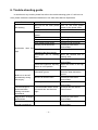
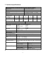
1
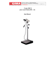
AM-4000 Surgical Microscope User’s Manual . Alltion (Wuzhou) Co., Ltd. Alltion (Guangxi) Instrument Co., Ltd. Alltion Building, No. 10, 3rd Road, Industrial Boulevard, Wuzhou Industrial Park, Wuzhou, Guangxi, China. 543100 Tel: +86-774-2836101(3 lines) Fax: 0774-2836192 Email: [email protected] or [email protected] Web site: www.alltion.com & www.alltion-microscope.com -1- Preface Thank you for purchasing our AM4000 Surgical Microscope. To prevent damage to your product or injury to yourself or to others, read the following safety precaution in their entirety before using this equipment. Keep these safety instructions where all those who use the product will read them. Precautions 1. Do not use this instrument in the environment prone to fire and blast or where there is much dust and with high temperature. Use it in the room and simultaneously be careful to keep it clean and dry; 2. Check that all the wires are correctly and firmly connected before using. Ensure that the instrument is well grounded. 3. Please pay attention to all the rated values of the electrical connecting terminal. 4. Only use fuse according to the specifications and rated values stipulated by our product. 5. Use the power cable supplied with this instrument only; 6. Do not touch the surface of the lens and prism with hand or hard objects. 7. Turn off the main power first before replacing the illumination bulb and fuse. 8. To prevent the instrument from falling down to floor, it should be placed on the floor where the inclination angle is less than 10º. 9. Turn off the power and cover the instrument with dust-proof hood when it is not in use. 10. In case there is any trouble, please first refer to the trouble-shooting guide. If it still can not work, please contact the authorized distributor or our After-sales Service Department. * THE SAFETY MARKS USED IN THIS INSTRUMENT This iron marks warnings, information that should be read before using your product to prevent possible injury. Terminal of the protective grounding. -2- Be careful of burns Contents 1. Feature and Specification ·······························································································1 1.1. Purpose ···················································································································1 1.2. Feature ····················································································································1 2. The names and Use of components···········································································2~5 3. Assembly·······················································································································6~8 3.1. Assembly of Base ·································································································7 3.2. Assembly of Arm ···································································································7 3.3. Assembly of 120ºcoupling ····················································································7 3.4. Assembly of Microscope ·······················································································7 3.5. Assembly of 180ºinclinable binocular ··································································7 3.6. Assembly of Handle ·································································································7 3.7. Assembly of LED power cable·················································································8 3.8. Assembly of Power cable 4. ······················································································8 Operating Instruction····································································································8~11 4.1. Necessary working condition ···················································································8 4.2. Precautions of using ································································································8 4.3. Installation and Adjustment before Using ······························································9 4.3.1 Adjusting the balance of Second Arm ························································9 4.3.2 Adjusting the Microscope············································································9 4.4. Inspection before Using·························································································9~10 4.5. Using process······································································································10~11 4.6. Movement and storage after Using···········································································11 5. Maintenance ············································································································11~12 5.1. Replacement of Consumable parts·········································································11 5.1.1 Replacement of bulb ·················································································11 5.1.2 Replacement of fuse ·················································································11 5.2. Cleaning and disinfection ·······················································································12 5.2.1 Cleaning the surface of equipment····························································12 5.2.2 Cleaning the surface of optical lens···························································12 5.2.3 Disinfection································································································12 6. Trouble shooting Guide··································································································13 7. Specifications···················································································································14 -3- 1. Feature and Specification 1.1 Purpose The AM4000 is used to ENT surgery, Dental surgery, ophthalmic surgery, Neurosugery, Gynaecologic surgery, Dermatology etc. 1.2 Features AM4000 employs Hanging arm design, this helps operator by automatically adjusting the exposure, ease and fatigue is minimized even after prolonged use. Six–step magnifications for main microscope, the optical system assures more clarity image. Adopts cool illumination, to prevent tissue distortion. Lighting conditions are provided by the LED lamp, Adopts “Spring Balance”design, the arm can be moved random. A special switch has been fitted into the Second Arm, the lamp will keep “on”when it is working in the normal range, otherwise the lamp will turn off by automatically. -4- 2. The name and use of components Fig.1 General assembly drawing of microscope -5- Fig.2 Back-side viewing [1] Star handler fixation screw Hang the microscope on the second arm using this nut. [2] The balance adjusting screw for Second Arm Rotate the screw with 8mm special Spanner to adjust the balance of the Second Arm. [3] Star handler fixation screw Use this handler to adjust the vertical moving balance on the Second Arm. [4] Fixation nut Hang the microscope on the second arm using this nut. [5] Star handler fixation screw Use this handler to adjust the horizontal moving damping the First Arm. -6- [6] Main power socket, fuse socket Pull out the power table, right side is fuse socket, fuse specification: T1.25 A/H250 V for 220VAC; T2.5 A/H250 V for 110VAC. [7] Main Power Switch To turn on or turn off the main power of equipment. [8] Foot Wheel Stamp the brakes to fix the equipment. [9] Star handler fixation screw Use this handle to adjust the damping 120ºconnecting arm. [10] Illuminate brightness adjusting button Rotate this button to adjust the illumination brightness. A sensitive switch set in the Second Arm, the bulb is light while the Second Arm move in working scope, otherwise the bulb will turn off automatically. [11] 12.5X Eyepiece There are Diopter adjustment hoop and Eye cover adjustment hoop. [12] LED power cable and the joint for power cable. [13] Magnifying knob By turning the knob, six magnification of main microscope are available(γ=0.3x,γ=0.5x, γ=0.8x,γ=1.2x,γ=2x,γ=3x). [14] Button to select filter Rotate this button to select the filters. There are three filters for selection: None filter/Green filter/Yellow filter [15] Manipulating handle For rough focusing, move the microscope up and down or right and left. Available in Type ‘ 8’. [16] Fixation nut Hang the microscope on the 120ºcoupling using this nut. [17] Star handler fixation screw Use this handle to adjust the damping microscope’ s hanging axis. [18] Star handler fixation screw Use this handle to adjust the damping microscope’ s pitching. -7- [19] Locking pin Avoid the microscope falling when assembling and disassembling instrument or when the according screw becomes flexible. [20] Fixation screw of main microscope Used to fin the main eyepiece tube. [21] Manipulating handle position For rough focusing, move the microscope up and down or right and left. Available in Type ‘ T’ . [22] Fine focusing adjustment knob Rotate this knob to adjust the focus of Objective, focusing distance: 11mm. [23] 110V/220V Voltage Selector Pushing the selector upwards, input voltage is 110V, pushing the selector downwards, input voltage is 220V. [24] Built-in camera joint Used to adjust the Built-in camera [25] The joint for monitor It can output video of built-in camera. -8- 3. Assembly This equipment is packed in one package. Please open the package and take out all parts and assemble them according to the following procedures. Fig 4 Assembly drawing of Microscope -9- 3.1Assembly of base (1) Please take out the base support from the package, lay it on the ground. (2) Take out the pole, turn out the inner hexagonal screw and gasket of its end, insert it into the hole of the floor stand, then turn to make the column pin on the base support clip in the groove on the end of pole, assemble in order the unassembled gasket, spring gasket, socket screw and fasten it firmly with 8mm Allen. 3.2 Assembly of arm Take out the arm,please pay more attention, the Star handler fixation screw [3] must be tightened, insert the hole to the Axis, then use the special tool to fix the two axis with spring screw in the circle groove, put on the cover. Caution:The Second Arm use the spring to keep the balance. The Star handler fixation screw [3] only to tighten the arm, the arm can not be locked by this screw. The Second Arm must be held before loosen the Star handler fixation screw [3]. 3.3 Assembly of 120ºcoupling (1) Rotate the Star handler fixation screw [9] a little bit until the screw tip does not above the hole; Rotate the Locking pin [19] a little bit until the tip does not above the hole. (2) Take out the Fixation nut [4] from 120ºcoupling, lay a little bit engine oil or Vaseline on Axis, insert the axis into the hole of Second Arm from the bottom to up, tighten the locking pin [19] make the locking pin [19] into the axis groove, tighten the Fixation nut [4] finally. 3.4 Assembly of microscope Take out the microscope, it connect with the hanging axis. Use the method as same as 3.4 to assemble the microscope to 120ºcoupling or the Second arm. 3.5 Assembly of 180ºinclinable binocular Take out the 180º inclinable binocular from the package, fix it to the main body of microscope, make sure the pin on the right tack, then tighten the screw [21]。 3.6 Assembly of Manipulating Handle -10- Manipulating handle [15] was fixed on the lower part of microscope, T type handle [21] was fixed on the front of microscope. Assemble the manipulating handle [15] or T type handle supplied with this equipment, then tighten the screw. 3.7 Assembly of the LED power cable The LED power cable has fixed on the First and Second Arm, plug LED power cable into the joint [12].. Caution:The terminals of LED power cable must be pluged in the right holes of the joint. 3.8 How to connect the power cable Take out the power cable and plug into power socket [6]. 4. Use of equipment 4.1 Necessary working condition Please make sure the following items, then enter into the next operation: ● Please check whether the main voltage, frequency complies with what required by the equipment. Set the input voltage at 220V. When it is 110V, please switch the selecting switch [23] to the 110V block and change the fuse as type T2.5 A/H250 V we supplied。 ● Check the grounding of power supply. Make sure the equipment have a good ground-wire connection. ● Please use the power cable supplied with this equipment. ● Please make sure that all mechanical parts concerned security should be assemble on the right way. 4.2 Precautions of Using ● Please never watch the light source directly through the objective. ●The terminals of LED power cable must be pluged in the right holes of the joint. ● Please do not cover the Heat elimination groove of power source。 ● Please pay more attention to the caution signs on the equipment. 4.3 Installation and Adjustment before Using 4.3.1Adjusting the balance of Second Arm -11- ● Hold the Second Arm, unscrew the Star handle fixation screw [3]. ● Insert a 8 mm special spanner into the screw [2]. ● Rotate the screw [2] to adjust the balance of Second Arm. ● Adjust the Second Arm, check the balance of Second Arm in multiple positions. ● Adjust the Star Handle fixation screw [3] until the upwards resistance and downwards on are almost equivalent. ● When increase/decrease parts, re-adjust the balance of Second arm are requested. Caution:The Second Arm must be held before unscrew the Star handle fixation screw [3]. 4.3.2 Adjusting the microscope ● Making the adjustment be original position, switch to 0.3X magnification,adjust the working distance of microscope and pupil distance. ● Emmetropes:adjust the eyepiece to 0; operator with his/her glasses: adjust the eyepiece to 0; Ametropes(who know their refractive powers and perform surgery without wearing their glassed):adjust the eyepiece to his/her own eyesight. ● Aametropes(who do not know their refractive powers and perform surgery without wearing their glassed):adjust both eyepieces to +5D,take the eyepiece and eyepiece tube from the microscope, observe distant object, just like use a telescope. Then rotate the diopter adjustment hoop until feels the image clear. If necessary, please repeat this process for three times. Use the same method to adjust the second eyepiece. Assemble the eyepiece and eyepiece tube back to microscope body, tighten the fixation screw [20]. ● Adjust the eye-cover until observe the whole visual field. Adjust the magnification to 3X, when you feel image clear, return to the magnification you want. The image still clear when you change the maginification, but different deep in each maginfication. Caution: It is necessary to make a form if several doctors share an operation microscope. Every doctor’s diopter should fill into the form and keep the form where all those doctors use the microscope will read them. 4.4 Inspection before Using Please make an inspection before the operation according to the following requests: - Check all fixation screws and lock pins have already been tightened. - Turn on the power switch, then check the following items: Illumination: ● LED, LED should be in good condition. -12- ● Moving the Second Arm up and down, the LED can be on-off in gear. The LED light when moving the Second Arm in right scopes, whereas the LED turn off automatically. ● The LED power cable has been connected. Set balance: ● The column system has been adjusted. ● The damping of First Arm, Second Arm, 120ºconnecting arm (optional accessories) and microscope have already been adjusted. Microscope: Adjusting the Magnification: ●Magnifying knob [13] could working. Eyepiece: ● The screw [11] to fix the eyepieces has been tightened. ● Operation Microscope and eyepieces have been adjusted into a suitable position for operation. ● Pupil distance has been adjusted. ● The eye-cover height has been adjusted that could observe the whole visual field. ● The diopter has been adjusted. ● The images are clear in each magnifications. Filter selector: ●Filter selector [14] is in good condition. Base: ● The foot wheels have been braked. Disinfection cover and handles: ● Star handle fixation screws, Magnifying knob, Illuminate brightness adjusting button、 pupil distance adjustment knob, Fine focusing adjustment knob ect. have been equipped the sterile covers. Microscope head may equip a single use sterile cover according to doctor’ s requirement. 4.5 Using Process - Please make sure the above steps had been finished. - The equipment had been inspected according to the requests of Inspection Form. ● Turn on the power switch. ● Move the second arm up and down to right working position. ● Adjust the illumination. ● Select the filter which will be used. ● Move the microscope lens into operation area, then adjust it to a suitable position. ● Adjust the magnifications. ● Move the operation microscope, adjust rough focusing through the eyepieces, then -13- adjust fine focus. ● Move the Second Arm to working scope. ● The equipment not in use should be switch off the main power. Caution:Make sure the Heat elimination groove are not covered. 4.6 Movement and Storage after using ● Put off all of the sterilized cap and handle, disinfect them for the next use. ● Furl the microscope back to the nearest position of column. Fasten every star knobs firmly so as to fix the arm and the microscope. ● Loose the brake of the wheel. ● While moving the equipment, hold the movement handles and make the equipment move slowly and carefully to avoid falling and bumping. ● While moving to the storage place, stamp the brakes. ● Put on the dust cover. 5. Maintenance 5.1 Replacing the consumable parts 5.1.1Replacing the LED Please contact the After-sales service Dept. 5.1.2 Replacing the fuse The fuse was integrated with main power input socket. Please replace the fuse according to the following steps: ● Turn off the main power switch. ● Pull out the power plug from the main power plug [6]. ● Fuse socket on the right side of power plug [6], take out the fuse socket from the side with a special tool. ● Take out the melted fuse. ● Insert a new fuse, and insert the fuse socket back again. ● Plug in power cable. ● Turn on the main power switch. Specification of fuse:T1.25 A/H250 V for 220VAC T2.5 A/H250 V for 110VAC Caution:Please use the special bulb for the equipment 5.2 Cleaning and Disinfection -14- Caution: The dirt on the lens must be cleaned immediately after the surgery. It will hard to clean when the dirt air-dried. 5.2.1 Cleaning the surface of equipment The outer surface of the equipment may be cleaned with wet cloth. The remaining stains can be cleaned off with the mixture of 50% C2H5OH and 50% distilled water. Do not wipe with any corrosive detergent lest that the surface should be damaged. 5.2.2 Cleaning the surface of optical lens To prevent the dust stained on the lens, never expose the optical lens to air without objective, eyepiece tube and eyepiece. Please use the dust cover after using. Cleaning the surface of optical lens: To clean the dirt on lens, such like bloodstain, please use the special paper or absorbent cotton with little bit distilled water and wash, the remaining stains can be cleaned off with the mixture of 50% Ethanol and 50% Aether. If there is dust stained on the lens, blow them with a blowball or brush them with a dust pen. Do not wipe with any corrosive detergent lest that the lens should be damaged. 5.2.3 Disinfection All sterilization caps should be sterilized by autoclave. The following temperature and time are recommended: (1) 120℃ for 10 minutes; (2)134℃ for 5 minutes -15- 6. Trouble-shooting guide In case there is any trouble, please first refer to the trouble-shooting guide. If it still can not work, please contact the authorized distributor or our After-sales Service Department. Trouble Not working Possible reason Remedy Not turn on the main power switch Turn on the main power switch or plug power cable. Main power broken-down Contact a local electrician Did not switch on the main power. Switch on the main power. The fuse tube has been melted Replacing the fuse Power cable broken-down Replacing the power cable Main power broken-down Contact a local electrician Electric part broken-down Contact the After-sales service Dept. Illumination does not The LED power cable is not light inserted to the joint correctly. Microscope area. not in working Insert it to the joint correctly Move the Second arm to working area. The LED has burnt. Contact the service Dept. Illuminate brightness adjusting button is in low position Adjust the button to the high position Something covered the Heat elimination groove. Take away the cover. Clean the Heat elimination groove. Blower fan broken-down. Contact the After-sales service Dept. Electric part broken-down Contact the After-sales service Dept. The microscope is obstructed when making movement downwards. The star handle fixation screw of second arm was fixed too tight. Re-adjust the Star handle fixation screw. Magnification changing broken-down - Contact the After-sales service Dept. Filtes has troubles orcould not switched. - Contact the After-sales service Dept. Bulb turn on and off automatically during the surgery. -16- After-sales 7. Technical specifications: Microscopes Section (including Binocular microscope, Objective, Eyepiece) Magnification 0.3x,0.5x,0.8x,1.2x,2x,3x Objective 250mm Fine Focus by a knob on objective 11mm Binocular 180°inclined or straight, F=170mm Adjustable Range for Pupil Distance 55mm~75mm 12.5X/17.7B, adjustable dioptor: ±7D Eyepiece magnification Magnification 0.3x 0.5x 0.8x 1.2x 2x 3x charger Magnification 2.8x 4.2x 6.9x 10.4x 17.0x 25.6x Diameter of 78.0 32.0 21.0 13.0 9.0 52.0 Field-of-view(mm) ﹥50,000lx Coaxial Illumination Φ62 Illumination diameter of light spot (mm) Stand Section (including Base, column, first arm and second arm) Second Arm Length 600mm Rotational angle ±150° Distance ±300mm First Arm Length 500mm Rotational angle 360° Height 1750mm 610×600mm Base dimension Electrical specifications AC230V±10%/50Hz, AC120V±10%/60Hz Rated voltage Input voltage 40VA Fuse AC 120V T2.5 A/H250V AC 230V T1.25 A/H250V Electrical Safety Standard IEC60601.1 Illumination Source Supplies bright, white and shadow-free light, >20,000 hours lifetime +10℃~+40℃ Use Condition Environment temperature relative humidity 30%~75% atmospheric pressure 700 hPa~1060 hPa -40℃~+55℃ Shipping and Storage Environment temperature relative humidity 10%~90% atmospheric pressure 500 hPa~1060 hPa ★ Items and specification subject to change, please contact Alltion for current product -17- information. -18-