1
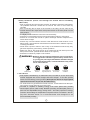
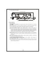
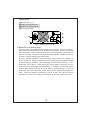
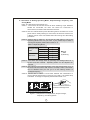
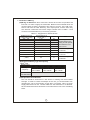
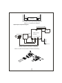
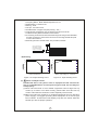
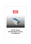
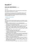
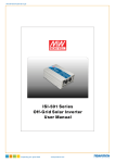
TN/TS-1500 Inverter Instruction Manual TN/TS-1500 Inverter Instruction Manual Index 1. Safety Guidelines ............................................................................... 1 2. Introduction ........................................................................................ 1 2.1 Features ........................................................................................ 2 2.2 Main Specification ........................................................................ 2 2.3 System Block Diagram .................................................................. 3 3. User Interface ...................................................................................... 3 3.1 Front Panel .................................................................................... 3 3 .2 L ED Indicato r on Fro nt P ane l ...................................................... 4 3 .3 F unc tion al Indic atio n an d A larm ................................................ 4 3 .4 R ear Pan el .................................................................................... 5 4. Explanation of Operating Logic ........................................................ 5 4 .1 Explanation o f UP S Mode Control Logic .................................... 6 4 .2 Explanation o f En ergy Saving Mode C ontrol Logic ................... 8 5. Initial Setup o f TN /TS-1500 ............................................................... 9 5 .1 Initia l State .................................................................................. 9 5 .2 Initia l Se t Po int for Transitio n Voltages ..................................... 9 5 .3 Procedure of S etting Operating M ode , Ou tput Voltage , Frequency, and Saving Mode ...................................................... 10 5.4 Remote Monitoring So ftware ....................................................... 12 6. Pro tection ........................................................................................... 12 6 .1 Input Pro tec tion ........................................................................... 12 6 .2 O utp ut P rote ctio n ........................................................................ 13 7. Ins tall ation & Wiring .......................................................................... 14 8. Failure Correction Not es ................................................................... 17 9. Warran ty ............................................................................................. 17 Feb. 2013 Version 13 1.Sa fety Guidelines (P lease read through this man ual before ass embling TN /TS-1500) ‧Risk of electrical shock and energy hazard. A ll failures sh ould be examined by the qualified technician. Please do not rem ove the case of the inverter by yourself! ‧After connec ting the AC input of the inve rter to the utility, the AC outlet of the inverter will h ave AC output even if the power switch on the front pane l is in the O FF position . ‧It is highly recommen ded to m oun t the unit horizontally. ‧Plea se d o no t install the inverter in places with hig h moisture o r nea r wa ter. ‧Plea se do not instal l the inverter in places w ith high ambient temperature or under direct sunlight. ‧Plea se only connect batterie s with the same brand and model number in one battery bank. Using batteries from different m anufacturers or different cap acity is strictly prohibited! ‧Never allow a sp ark or flame in the vicinity of the ba tteries b ecause they may generate explosive gases during normal operation. ‧Make sure the air flow from the fan is no t obstructed at both sides (front an d back) of the inverter. (Ple ase allow at least 15cm of spa ce) ‧Plea se d o no t stack any object on the inverter. WARNING: Batteries will have aging problem after years of operation. It is suggeste d to exe cute re g ul ar battery maintena nce (e.g. every year). Once aged, the batteries should be changed by professional technician, or the failed batteries may cause fire or other hazards. Inverter Inverter Don't disasse mble Away fro m moistu re Inverter Away from fir e or h igh temperature Don't stack on the inverter Inve rter K eep good ve ntilation 2.Introduction ‧Fully digital con trolled by a n advanced CP U, T N-1500 is a tru e sine wave inverter equipped with a n AC charger and solar charger. It can also operate under UPS and E nergy saving modes. (D escriptions which are high lighted represents func tion s only for the TN-15 00 series) ‧TS-1500 series only possess the inve rter function . It uses batterie s as the input source and converts the energy into A C output. ‧TN-1 500 is cap able of drawin g energy from so lar panel thus pro vide uninterrupted power (UPS mode). B esides p roviding uninte rrup ted pow er, it also has use r adjustable ene rgy saving mod e. The main purposes of energy redu ction and bu ilding an indepe nden t su b power station are realized. We can s ay tha t T N -1 5 00 se r ies is a m ult i -fu nct i o na l an d d esi g ne d to b e environm entally friendly. 1 ‧TN-1500 series will autom atically detect the input sources (whether AC main or solar panels exist) and then adjust its internal setting. Users ca n also set up the operatin g mode, output voltage, frequency, and saving mode by themselves based on their special needs, geographic area, and environmental conditions. ‧With pure sine wav e output, TN/TS -1500 can provide 1500W continuously, 1750W for 3 min utes, or 20~40A of peak current for all kinds of load such as inductive, capacitive, or re sistive. General applications in clude PC, ITE, vehicles, yachts , home applian ces, motors, power tools, industrial control equipme nts, AV system, a nd e tc... 2.1 Features ‧Selectable UPS or Energy saving mode ‧So lar charging current 3 0A max ‧True sine wave output (THD<3%) ‧Fa st transfer tim e 10ms (Ty p.) ‧1500W rated output ‧H igh effic iency up to 90% ‧C om plete LE D ind ication for opera ting status ‧Battery low a larm and indicator ‧Surg e power capability up to 3000W ‧O utput vo ltage / frequency selecta ble ‧Fully digital controlled ‧C om pliance to UL458 / FCC / E 13 / CE ‧C an b e u sed for m ost of electronic products with AC inp ut ‧3 year glo bal warranty 2.2 Main Specific atio n MODEL Rated power Surge Curren t Factory set ting Output voltage O U T P U T Frequency WAVEFORM 112 12 4 148 212 224 248 1500W max. continuously, 1750W max. for 180 seconds, 1875W max. for 10 seconds, 3000W for 30 cycle 110V 60Hz 2 30V 50H z 100 / 110 / 115 / 120V 2 00 / 220 / 230 / 2 40V 60±0.1 Hz 5 0±0.1Hz True s ine wave (THD < 3.0%) PROTECTION AC sh ort、Ove rload 、 Over Tem perature BAT. VOLTAGE 10.5 ~ 15.0V 21.0 ~ 30.0V 42.0 ~ 60.0V 10.5 ~ 15.0V 21.0 ~ 30.0V 42.0 ~ 60.0V I N P U T C H A R G E R DC CURRENT 150A EFFICIENCY 87% OFF MODE CURRENT DRAW PROTECTION CHARGE VOLTAGE AC CHARGE CURRENT SOLAR OPEN CIRCUIT VOLTAGE SOLAR CHARGE CURRENT 75A 89% 37.5A 89% 150A 88% 75A 90% 37.5A 91% Under 1 .0mA at power s witch OFF Over current、battery polarity reverse by fuse、battery low shutdown、battery low alarm 14.5V 29.0V 58.0V 5.5A ±0 .5A 2.7 A ±0.4A 25Vmax 45Vmax 29.0V 58.0V 1.35A ±0.2A 5. 5A ±0.5A 2.7A ±0.4A 1.35A ±0. 2A 75Vma x 45Vmax 75Vmax 30A ma x. 2 14.5V 25Vmax 2 .3 S yste m B lock Dia gra m TN-1500 Inverter E MI fi l ter AC Input CPU C ontroll er LED Display AC ch arger F use Circui t Break er Solar c harger 200V DC /400V D C Battery 12V/2 4V /48V Fuse Polari ty detect DC/ DC Converter DC/AC Inverte r 12 0V/230V 50 Hz/60H z LOAD AC Output Solar P anel Figure 2.1 System Block Diagram 3.Use r interface 3.1 Front Panel A PO WE R on/off sw itch : The in verte r w ill turn OFF if the sw itch is in the OF F positio n. B AC output outlet: To sa tisfy ap plication dem and of d ifferent geograp hic areas all over the world, there are many optional A C outlets to choose from. C No Fuse B reaker; Re set: Under "Bypass Mode", when the AC outp ut is shorted or the load current exce eds the rated curren t of the No F use Breaker, the No Fus e Breaker will open and that stop s bypassing energy from the utility getting to prevent poss ible dang er. Whe n the ab normal operating condition is rem oved, user can press down o n the Re set button to resume operation. D Ve ntilation ho les: The inverter require s su itable ventilation to w ork pro perly. Please make sure there is good ventilation a nd the lifesp an of the inv erter can preserved. E Fu nction Setting: Operating Mode, O utput vo ltage, frequ ency, and saving mode can be set through this button. F LE D Indic atin g Panel: Operating sta tus, load condition, and all type s of warnin gs w ill be displayed on this panel. G Communication Port: For remote m onitoring purpo se, the unit can b e connected to a PC through this com munication port b y using the o ptional cable and monitoring software. 3 B F AC OU TPU T S OLA R CHARGE ON AC CHA RG E A 100 OFF B ATTE RY Se ttin g LOA D E 1 00 INV ERT ER On 0 0 C AC I N BY PAS S Ba t Lo w Sa vin g G Remote port D F igure 3 .1: Front Panel (T N-1500) 3 .2 LED Indicato r on Front Panel Ba ttery Ca pacity Indicator: represents the remaining capacity of external batteries. LED Display LED 1 ON LED 1~ 2 ON LED 1 ~ 3 ON LE D 1 ~ 4 ON Battery 0 ~ 25% 26 ~ 50% 51 ~ 75% 7 6 ~ 100% Capacity Load C ond ition Ind icator: repre sents the magnitude of output loads. LED Display LED 1 ON LED 1~ 2 ON LED 1 ~ 3 ON LE D 1 ~ 4 ON Battery 0 ~ 30% 30 ~ 50% 50 ~ 75% 7 5 ~ 100% Capacity 3 .3 Function Indication a nd Alarm ◎ O n : The inverter sta rted up and outpu t is norm al. ◎ B at L ow : Voltage of external batteries is too low. The inverter will send ou t a "B eep" sound to warn th e u sers. ◎ Savin g : The inverter is ope rating un der the "Saving Mode" and there's no AC o utput. ◎ AC CHAR GE : The built-in AC cha rger is charging exte rnal batteries. ◎ S OLA R C HARGE : The external solar panels are provid ing energy to the external batteries through the built-in solar charger. ◎ AC IN: The s tatus of utility is norm al. ◎ BY PAS S: The unit is working under "B ypass Mode". The A C electricity consum ed by the loads is provided by the utility instead of the inverter. ◎ INVERT ER: The unit is working under "Inverter Mode" The AC electricity consum ed by the loads is con verted from the batteries . ◎B AT TERY: D ispla y the remain ing cap acity of external batteries. ◎LOA D: D isplay the output loa d status. 4 3.4 Rear Panel A Battery input (+), (-). B Utility / AC inlet (IEC 320). C Solar panel input terminal. D Frame ground (FG). AC INPUT Solar Input (30A max) NEG B DC INPUT POS Reverse Polarity Will Damage The Uni t. Chassis Ground C A Cat .No.(1 GG1 HS-212 ) Wire Ran ge(10-4AWG Str Cu So ldere d Wires ) Torque ( 17.7 -26.5 in lb) D Fig 3.2: Rear Panel (TN-1500) 4.Explanation of Operating Logic TN -1500 (CPU controlled inve rter) is des igne d to achiev e the go al o f en ergy saving and pos sesses both UP S an d Energ y sa ving mo des . Th ese 2 modes are us er adjus table. T he unit will be facto ry s et in the UP S m ode . D ependin g on we ather an d utility conditio ns, use rs can m anu ally adjust o r use th e monit oring software to switch to the Energy sav ing mod e. Th e main difference between UPS and En ergy saving mo de is the amount o f energy con served. Under the U PS mode, the unit will remai n in the B ypa ss m ode as long as utility is availabl e. Thus less energy is conserved (refer to Fi g. 4.1 for UPS m ode control logic). Under the E nergy saving mode, the priority of inpu t source cho sen is solar pan el AC m ain battery. If a vailable, the CP U will select external solar panels a s its first priority in orde r to conserve en ergy. In case o f insufficient sol ar power and utility failure, battery power will be draw n as the last resort. When the capacity of batteries is around 1 0~20%, the CPU will re mind end users by continuou sly sending out w arning siren until the system shuts d own . 5 4.1 Expla nation of UPS Mode Control Logic ON ON Utility Power OFF OFF Power-On Re-power-on ON ON By pass mode OFF OFF ON Inverter Mode OFF 28.5V t ON ON OFF OFF t 28.5V 28.5V 28.5V 25.4V 26.5V 26.5V 22.5V (Alarm) 26.5V Battery voltage 21V(Shut-down) t 29.0V Solar charger state AC charger state ON ON ON OFF ON t2 OFF OFF OFF t3 t ON OFF t1 OFF OFF ON ON t4 t5 t6 t7 t8 t9 t10 t t11 t12 Figure 4.1: D iagram of UPS M ode Control Log ic t1: To ensure the battery is at full capacity, when the T N-1500 is turned on , the CPU will execute th e "Bypa ss M ode" automatically connecting the AC main to the loa d. In the m ean time, it will activate both th e A C charger and solar charger to simultaneou sly charge the batteries. t2: Wh en the batte ries are full (battery voltage around 28.5V), both the AC and solar charger will be turned off by the C PU to prevent overcharging and reducing the battery lifetime. In the meantime, the system will remain in the "Bypass Mode" and AC electricity provided to the loads is coming from public utility. 6 t3: At this time period, TN-1500 is still in the Bypass mode. The battery voltage level w ill d ecrease gradually d ue to standby power dissipation. Whe n the batteries a re c onsumed to around 75% of their c apacity (ba ttery voltage around 26.5V) the CPU will restart the charger. The CPU will use charging current of 3 A as a guide point. When the provided charging current is u nder 3A , the AC charger will be turned ON (e.g. Night tim e or cloudy day). As for charging current of ove r 3A, the solar charger will be turned O N in stead. t4: If the energy provid ed by th e charger is larger than what is cons umed by the load, voltage o f battery bank w ill increase gradually u ntil 28.5V is rea ched then the CPU will be s hut off the charger to preve nt overcharging. A t this point, output lo ad is still supplied by utility. t5: Since the chargers are in the OFF mode, the battery voltage will grad ually decrease to the range o f 26.5~28.5V (floating voltage le vel). If utility were to fail at this mom ent, the CPU will automatically switch (<10m s) to the inverter mode insuring u nin terrupted po wer. t6: Once utility recovers, the CP U will switch back to the bypass mode. t7: When battery voltage drops to below 26.5V, the battery charger will be activated to charge the ba ttery bank (refe r to t3 for detailed description). t8: Same as t4. t9: Du e to lack of utility, TN-1500 will switch to the inverter mode. AC charging functio n will be turned off. Since AC output relies pu rely on battery power, the battery bank will be deplete d rather quickly. t10: A s the battery di scharges to belo w 26.5V and utility remains una vai lable. O nly the sola r ch arger is turned ON. The battery bank could be depleted rather quickly. t11: Same as E nergy Savin g mode. t12: When sola r ch arger is providin g current of larger than 3A, the vo ltage lev el o f the battery bank w ill rise slow ly. O nce the ba ttery voltage reaches inverter m ode reactivation level, the inverter will be revived. 7 4.2 Expla nation of Energy Saving Mode Control Logic ON Uti lity Power OFF Power-On ON ON Bypass mode OFF O FF ON In verter mode ON O FF O FF OFF 28.5V 28.5 V 28.5 V 26.5 V Bat tery voltage Solar charg er state AC ch arger st ate 22V ON ON 21 .0 V (Sh ut-down) ON OFF t ON ON OFF t1 t ON OFF O FF O FF t 28.5 V 26 .5V 22.5 V (Alarm) 22 .5 V (Alarm) 26.5 V t ON t2 t3 t4 O FF t5 t6 t7 t t8 F igure 4.2 Diagram of Energy Saving M ode Control Logic t1 : When the TN-1500 is turned on, CPU will execute the "Bypas s Mode" automatically conn ecting the A C m ain to the lo ad. In the m ean tim e, it will activate both the A C charge r an d so lar charger to simultaneously ch arge the batteries. t2 : When the batteries are ful l (ba ttery voltage around 28.5V), both the AC and solar charger will be turne d off to prevent overcharging a nd reducing the battery lifetime . In the m eantime , the system will switch to the "Inverter M ode" and the AC electric ity provided to the loads will be coming from the batteries. t3: When the batteries are de pleted to around 75% of their capacity (battery voltage aro und 26.5V), CP U w ill restart the solar cha rger but not the AC charger to achieve the purpose of en ergy-saving. t4: If the energy provided b y the solar p anels is larg er than the load requirem ent, voltage of battery ban k will increa se gradually until reaching 90% capacity (battery vo ltage around 28.5V) and then the solar charger will be shut off to prevent the batteries from overcharg ing . 8 t5: When the capacity of batteries go down to about 75% (battery voltag e around 26.5V), solar charg er w ill restart and beg in charg ing. t6: If the energy provided by the solar panels is lower than consumed by the loads, voltage of battery bank w ill decrease gradually to 20% of its capacity (battery voltage aro und 22V), the b uilt-in bu zzer will be activated and inform the users to take proper action. t7: If the power consumption of the loads d oes not decrease an d the AC main is normal, CPU w ill detect this and the unit will be transferred to "Bypass Mo de". Th e utility will provide energy to the loads and charge th e battery ba nk at the same time in order to preve nt the un it from shutting off. If the so lar current is higher than 3A , the CP U will not a ctivate the "AC charger" and just let the "Solar Charger" charge the batteries to achieve the goal of energy-saving. t8: When lacki ng AC main, the C PU will shut down the whole system if the capacity of external battery bank is less than 10% (battery voltage around 21V) in order to p revent o ver-discharging and reducing its lifetime. After shut d own , the CP U will pro vide LE D in dication to the user know why the inverter has shut off. 5. Initial Setup of TN/TS-1500 (Operating Mode, O utput Voltage, Frequency, an d Saving Mode) 5.1 In itial Sta te Th e initial state of TN/TS-1500 is 120Vac/60Hz or 230Vac/50Hz and both the "UPS mode" and "Saving M ode" is activated. If the users ne ed to re vise it for certain app lication, it can be done throu gh the se tting bu tton on the front panel (Please refer to section 5 .3). The unit will start up autom atically after the setting procedure is finished and the new settings will be executed. These new settin gs will be kept even if AC, battery, and solar is disconnected or occurrence of fault condition s leading to failure of output voltage thus requiring p owe ring the inve rter OFF and ON . 5.2 In itial Set Poin t for Transition Voltage s TN /TS-1500 F acto ry S etting AC Cha rger Transition Voltage AC Cha rger Sta rt Up Vo ltage Solar C harg er Sta rt Up Vo ltage Solar Charge r Shut Dow n Voltag e Inver ter Shut Dow n 112 212 124 224 148 248 14 .3V 28.5V 57 V 11V 22V 44 V 13 .3V 26.5V 53 V 14.3V 28.5 V 57 V 10.5V 21 V 42 V 9 5.3 Proce dure of Setting Op erating Mode, O utput Voltage, Frequency, and Sa ving Mode Note: TS-1500 does not ha ve S tep 3~5. STEP 1: The inverter should be turned off while resetting. Input batteries should be conne cted, A C main ca n e ither be connected or di scon nected, and the loads should be removed . STEP 2: Use an insulated stick to press the setting button and then turn on the power switch. After pressing for 5 seconds, the inve rter will send out a "Beep" sound. Users can release the button and go into the setting procedure. STEP 3: P lease refer to Table 5.1 an d check the LED status to see if the Operating Mode is the one you need. If yes, please skip to STEP 5. If change is required, pleas e follow STE P 4~11. Table 5.1 Operatin g Mode Energ y Saving Mode U PS Mode On ● Bat Low ★ Saving ★ On ○ Bat Low ★ Saving ★ ● Lig ht ○ Dark ★ Fla shin g STEP 4: The LEDs w ill change state by pressing the setting button for 1 second and then rele ase. Operating Mo de can be adjusted as required. STEP 5: After selecting the Operating Mode, press the setting button for 3~5 seconds and the inverter will send out a "Beep" sound. Th e button can be released and you can g o on to the setting section of "Voltage/frequency." STEP 6: Please refer to Table 5.2 and check whethe r the co mbination o f output vol tage and frequen cy is the one you need. If yes, please skip to STE P 8. If change is req uired, please follow STEP 7~11. AC OUT PUT SOLAR CH ARGE ON AC C HARGE BATTE R Y OF F 100 Settin g LOA D 10 0 INVERTE R On 0 0 AC I N BY PASS Bat Low Saving Use an insula ted stick to press th is setting bu tton Remot e port Figure 5.1: Adjustment of Output Mode, Output Voltage, Frequency, and Saving Mode 10 Table 5.2 : LED Indication of Output Volta ge / Frequency Combination Outp ut Volta ge Frequen cy 1 00Vac (2 00Vac) 11 0Vac (22 0Vac) 115Vac (230Vac) 120Vac ( 240Vac) On 50Hz Bat Low Saving On 60Hz Bat Low Saving ● ○ ○ ★ ○ ○ ● ○ ● ★ ○ ● ● ● ○ ★ ● ○ ● ● ● ★ ● ● ● Light ○ Dark ★ Flashing STEP 7: The LEDs w ill change state by pressing the setting button for 1 second and then release (refer to Fi gure 5.2). Please select the combination of output voltage a nd frequency you need. 110Vac (2 20Vac) 50 Hz 115Vac (230Vac) 5 0Hz 1 20Vac (240Vac) 50Hz 100Vac (200Vac) 50 Hz 10 0Va c (200Vac) 60Hz 120Vac (2 40Vac) 60 Hz 110Vac (220Vac) 60Hz 115Vac (230Vac) 6 0Hz F igure 5.2: State C ircu lation Diagram o f Ou tput Voltage and Freq uency STEP 8: A fter sele cting th e ou tput voltage and frequency, pres s the setting button for 3~5 seconds and the inverter will send out a "Beep" sound. Th e button can be released and it will go into the setting section for "Saving Mode." STEP 9: Please refer to Table 5.3 and check whether the "Saving Mode" is set as required. If yes, pl ease skip to STEP 11. If change is required, pl ease fol low S TEP 10~11. Table 5.3 LED Indication for Saving Mode O N/O FF Sav ing Mode ON Sav ing Mode OFF On ★ Bat Low Saving ★ On ★ Bat Low ★ Saving ○ ● 11 ● Light ○ Da rk ★ Flashing STEP 10: The LE Ds will change state by pressing the setting button for 1 seco nd a nd then release . Yo u can activate or ca ncel the "Sa ving M ode" function by this adjustm ent. STEP 11: Afte r ac tivating or canceling the "Saving Mo de", press the setting button for around 5 seconds a nd the inverter will send out a "Beep" sound. The button can be released an d al l the settings are finished . The inverter will automatically sto re all the settings and then start to operate. 5.4 Remo te M onitoring So ftw are (A)Users can also make Operating Mode, voltage/frequency, saving m ode, and transition voltage adjustments by using this software. Software update can be downloaded from the MW we bsite. Please c ontact us or our distributor if yo u ha ve any questions. (B)DB9-USB conversion cable should not be use d because it will not be compa tible with the monitoring software. 6. Protection 6.1 In put Protection (A)Battery Polarity Protection: If the battery input is connected in reverse polarity, the internal fuse will blow and the inverter should be send back to MEAN WELL for repair. (B)Battery Under Voltage Protection: When the battery voltage is lower than the pre set value, the inverter will automatically terminate the output and "Battery Low" signal on the front panel will light up. Please refer to Table 6.1 for more detail about the failure signals d isplayed through the "Load M eter." (C)Battery Over Volta ge Protection: When th e battery voltage is too high , inverter will automatically terminate the output and the built-in buzzer will activate to inform the us ers. Please refer to Table 6.1 for more detail about the failure signals displayed through the "Load Meter." WARNING: Please choose suitable batteries that is within the rated input DC voltage of TN/TS-1500 (refer to the S PEC). If the input DC voltage is too low (ex. using 12Vdc battery bank for 24Vdc input models), TN/TS1500 can't be started up prop erly. If the input DC voltage is too high (ex. using 48Vdc battery bank for 24Vdc inp ut models), TN /TS-1500 will be damaged! (D)Solar C harger Over Cu rrent Protection: The m aximum chargin g current of the b uilt-in solar charger is 30A. If the charging current is too high, the internal fuse will blow and the inverter sh ould be send back to MEAN WELL for repair. 12 6.2 Ou tput Protection (A)Bypass M ode: Uses "No Fu se Breaker" as automatic over current protection. When over current occurs, the button of the circuit breaker on the front panel will pop up and the inverter will shut down. At this time, users should remove th e loads, restart the inverter and press down on the button of the circuit breaker and the AC output can now be provided normally. (B)Inverter M ode: Under the "Inverter Mode", if any abnormal situ ation occurs, the front panel will send out failure messages through the "Load Meter" (Please refe r to Table 6.1). (1)Over Temperature Pro tection: When the internal temperature is h igher than th e limit value , the "O ver Temperature Protection" will be activated. The unit will automatically turn off and should be restarted ag ain. (2)AC Output Ab normal Pro tection: When the AC output voltage of the inverter is too high or too low, the unit will turn off and should be restarte d again. (3)AC Output Short Circuit Pro tection: When a short circuit situation occurs at the output side of the inverte r or the load increase greatly in a short p eriod of time, the unit will turn off and should b e restarted again. (4)Battery Voltage Ab normal Pro tection: Wh en the battery voltage is too high or too low, this protection will be activated. T he inverter will autorecove r once the battery voltage go back to a safe level and users d o not need to restart it. (5)Ou tput Ove rloa d P rotection: When output is overloaded betwee n 15 00W ~ 1750W, the inverter can continuously provide power for 3 minu tes. After that, if the overload condition is not removed, the overload protection will be activated. When the load is higher than 1875W, the overload protection will activate instantly. For these ove rload protections, once activ ated, yo u should reset the unit. Table 6.1: Failure Mess ages On Fro nt Panel LOA D Fail ure Mes sage LOA D 10 0 LE D In dicato r F ailure Messa ge 10 0 LED Indicator 0 Output Overload (1500W~1750W) LOA D Output Overload (1750W~1875W) LOA D Output Overload (>187 5W) LOA D Ove r Temperatu re 0 Abnormal AC Outpu t Voltage 100 0 LOA D 10 0 0 LOA D AC Outpu t Short Circuit 100 10 0 0 0 Abno rmal Batte ry Volta ge 100 0 LO A D 1 00 0 13 LOAD 10 0 0 7. Installation & Wiring (A)Wiring for Batteries: Wire connections should be as short as pos sible and less than 1.5 meter is highly recommended. Make sure that suita ble wires are chosen based on Safe ty requirement and ratin g of current. Too small crosssection will result in lower efficiency, less outp ut power, and the wires may also become overheated and cause danger. P lease refer to Table 7.1 and consult our local distrib utor if you have any questions. Table 7 .1: S ugg esti on for Wire S election R ated Cu rren t of E quip men t (A mp) 10A ~ 13A Cro ss-s ecti on o f 2 Lead (mm ) 1.25 16 Choosing suitable wires based on the rating of solar panels and distance from the inverter 13A ~ 16A 1.5 14 16A ~ 25A 25A ~ 32A 2.5 12 4 10 32A ~ 40A 40A ~ 63A 6 10 8 6 63A ~ 80A 16 4 M ode ls us ing 48V b atte ries 80A ~ 100A 100A ~ 125A 25 35 2 1 M ode ls us ing 24V b atte ries ≧125A 50 0 M ode ls us ing 12V b atte ries (B)Suggested Ba ttery Ty pe and C apacity TN/TS-15 00 Battery Typ e Battery Capacity Input Current from Solar Panel Lea d-acid 112 212 12V / 120Ah ~ 12V / 400Ah 124 224 24V / 60Ah ~ 24V / 200A h 148 248 48V / 30Ah ~ 48V / 100Ah 5A ~ 25A (C)Requirement of In stallation: Th e unit should be mounted on a flat surface or holding rack with suitable strength. In order to ensure the life span of the unit, yo u sh ould refrain from operating the unit in enviro nment of high d ust or mois ture. This is a power supply with built-in DC fan. Please make sure the ventilation is not blocked. We recommend that the re should be no barriers with in 15cm of the ventilating holes. 14 >15cm >15cm Inverter Air Air Figu re 7.1: E xam ple of In stallation (D)Example of System Diagram As short as possible AC O/P So lar Panel Battery + - L arger than 1 5cm LOAD TN/TS-1500 Inverter Larger than 15cm AC I/P D C I/P -+ Solar I/P Chassis Sho uld less than 1.5m Base d on the actual lengt h of wiring and choose suitable c ross-section of t he leads Where, the DC I/P a nd c hassis fix manner as followin g : 15 Wall or system FG 1. Company N ame : Mean Well Enterprises Co Ltd 2. Model Name : 1GG1HS-191 3. Rating : 150A 4. Torque : 106.2 Ib.in max. 5. Suitable Wire : Copper wire (tem p rating : 75C ) 6. Intended for termination onto a Listed ring tongue connector 7. To Be Sold Onl y With Installation Instructions 8. A m oun ting screw that is first inserted throug h the tang and is threaded into the con nector to secure the connector to the tang shall be torqued to 32 in-lbs minimum 9. Mounting Screws - Plated Steel . Two provided, size M 4 Cat.No.(1G G1HS-212) Wire Range (10-4 AWG Str Cu Sold er ed Wires) Torque (17. 7-26.5 in lb) Chas sis (E)Derating 100 100 80 80 60 60 40 40 20 20 0 10 20 30 40 50 60 70 21VDC Ambient Temperature (℃) Figure 7.2: Output Derating Curve (F) 23VDC 30VDC (HORIZONTAL) Battery Input Voltage (V) - 24V Mode l Figure 7.3: In put Derating Curve Notes on O utput L oad s: T N /TS -1 5 00 S erie s c an po w er mos t of equip me nt s that nee d a n AC s o urc e of 15 0 0W. Bu t fo r ce r tain sp e cifi c ty pe o f lo ad , t he unit may n o t work properly. (1)Since inductive loads o r motor bas ed equipments n eed a large start up current (6~10 times of its rated current), please make sure this start up current is less than the maximum current capability of the inverter. (2)When the outpu t are capacitive or rectified equipments (such as switching pow er supply), we suggest operating these equipment a t no load or light load condition. Increase the loads slightly only after the TN/TS-1500 ha s started up to ensure proper operation. 16 8. Failure Correction Notes TN /TS-15 00 should serviced by a professiona l technician. Im proper usag e or m odification m ay d am age the u nit or result in shock hazard. If you are n ot able to clear the failure condition, please contact Mean WELL or a ny of our dis tributors for repair s ervice. S tatus N o AC output voltag e Possible Rea sons Ways to Eliminate Abno rma l inp ut C hec k the AC or D C in put sources . M ake sure the voltage is w ithi n the required rang e. No in put (battery, AC mai n, or solar e nergy) Make sure the w iring and polarity is correct. Over temperature prote ction M ake sure that the ve ntila tion is not b lock ed o r wh ether th e am bient temperature is too h igh. Please derate output usage or reduce the ambient temperature. Overload protection M ake sure the output load doe s no t e xceed the ra ted valu e or the instantan eou s sta rt up current is n ot too high (for inductive or cap acitive loads). Short circuit protectio n M ake sure the output is no t o verloaded o r short circui t Batteries are aging or broken R eplace the b atte ries D isch argi ng period of batteries is to o sh ort F an d oes not sp in Malfunction o f the charge r (no charging voltage) Reconfirm the specification and enlarge the battery ca pac ity a s su ggested R epa ir re quired. Plea se s end it ba ck to us or any o f our distribu tors Clog with foreign objects R emove the foreign objects Malfunction o f the fan R epa ir re quired. Plea se s end it ba ck to us or any o f our distribu tors Battery capacity is too small 9.Wa rranty Three years of global warranty is provided for TN/TS-1500 under normal operating conditions. Please do not change components or modify the unit by yourself or MEAN WELL may reserve the right not to provide the complete warranty. 17 N o . 2 8 , Wu q u a n 3 r d R d ., Wu g u D i s t . , Ne w Ta i pe i C i t y 2 4 8 , Ta i wa n