1
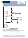
USER MANUAL V1.1 Decoding Gateway Firmware March 4, 2015 EnOcean GmbH Kolpingring 18a 82041 Oberhaching Germany Phone +49.89.67 34 689-0 Fax +49.89.67 34 689-50 [email protected] www.enocean.com Subject to modifications Decoding Gateway Controller User Manual V1.1 March 4, 2015 1:43 PM Page 1/11 USER MANUAL V1.1 DECODING GATEWAY CONTROLLER REVISION HISTORY The following major modifications and improvements have been made to the first version of this document: No 1.0 1.1 Major Changes Initial version Supported SLF range extended. Published by EnOcean GmbH, Kolpingring 18a, 82041 Oberhaching, Germany www.enocean.com, [email protected], phone +49 (89) 6734 6890 © EnOcean GmbH All Rights Reserved Important! This information describes the type of component and shall not be considered as assured characteristics. No responsibility is assumed for possible omissions or inaccuracies. Circuitry and specifications are subject to change without notice. For the latest product specifications, refer to the EnOcean website: http://www.enocean.com. As far as patents or other rights of third parties are concerned, liability is only assumed for modules, not for the described applications, processes and circuits. EnOcean does not assume responsibility for use of modules described and limits its liability to the replacement of modules determined to be defective due to workmanship. Devices or systems containing RF components must meet the essential requirements of the local legal authorities. The modules must not be used in any relation with equipment that supports, directly or indirectly, human health or life or with applications that can result in danger for people, animals or real value. Components of the modules are considered and should be disposed of as hazardous waste. Local government regulations are to be observed. Packing: Please use the recycling operators known to you. By agreement we will take packing material back if it is sorted. You must bear the costs of transport. For packing material that is returned to us unsorted or that we are not obliged to accept, we shall have to invoice you for any costs incurred. © 2015 EnOcean | www.enocean.com Decoding Gateway Controller User Manual V1.1 | Page 2/11 USER MANUAL V1.1 DECODING GATEWAY CONTROLLER TABLE OF CONTENT 1 GENERAL DESCRIPTION ................................................................................. 4 1.1 Basic functionality ......................................................................................... 4 1.2 References ................................................................................................... 5 2 FUNCTIONAL DESCRIPTION ............................................................................ 5 2.1 I/O description .............................................................................................. 5 2.2 Serial interface.............................................................................................. 5 2.3 Built-in Repeater ........................................................................................... 6 2.4 Security details ............................................................................................. 7 2.5 Operational modes ........................................................................................ 7 2.5.1 Teach In Functionality of Secure Devices .................................................. 8 2.5.1.1 Resynchronisation of Taught In Secure Devices ...................................... 9 2.5.2 Gateway Operational Functionality ........................................................... 9 2.6 Storage for Rolling Codes and Keys ................................................................. 9 2.6.1 Possible external memories ..................................................................... 9 2.6.2 Storage Selection ................................................................................ 10 2.6.3 Voltage drops ...................................................................................... 10 2.7 Configurations............................................................................................. 11 © 2015 EnOcean | www.enocean.com Decoding Gateway Controller User Manual V1.1 | Page 3/11 USER MANUAL V1.1 DECODING GATEWAY CONTROLLER 1 GENERAL DESCRIPTION With the Decoding Gateway, EnOcean now offers its OEM partners a firmware that decodes encrypted EnOcean telegrams on the module. This allows manufacturers (OEMs) to integrate encrypted data communication faster and more easily into their products, for example for safetyrelated and smart home applications. The Decoding Gateway adds an important module to the receiving side of EnOcean’s security portfolio. When a device using enhanced security features e.g. PTM 215 energy harvesting wireless switch module transmits encrypted telegrams with rolling code based on the AES 128 standard, the TCM 300 or TCM 320 transceiver module – programmed with Decoding Gateway – can decrypt these telegrams and then forward them to an external controller. With this approach, EnOcean adds the process of data encryption and decryption transparently to its modules. When manufacturers plan energy harvesting wireless applications with encrypted data transfer, they can save themselves this development step. The OEM’s external controller no longer has to decode the telegrams, but receives them already decoded and ready for immediate use. Security functions can easily be added to existing receiving and gateway products by programming the TCM 300 transceiver module with Decoding Gateway. During the programming process, the firmware stores the rolling code together with the corresponding key on the Dolphin chip, so that no changes need to be made to the hardware. Alternatively, OEMs can also store this information on a separate EEPROM, especially for new product developments. The security information is therefore stored outside the module’s program memory. 1.1 Basic functionality The Decoding Gateway is based on Gateway Controller and extends its functionality by security decoding of secure switch telegrams (e.g. PTM 215). The secure switch telegram is decoded by the firmware and passed on the UART interface decoded. Prior to decoding, the secure switch needs to be taught in by the decoding gateway. Key and Rolling code management is executed by Decoding Gateway. For a full specification please consider also the User Manual of the Gateway Controller (aka TCM 310). Features All features included in the Gateway Controller Decodes Telegrams from secure Switches Handling and storing Rolling Codes and Security Keys - Storing in external EEPROM - Storing in internal Flash Memory (Dolphin Chip) I2C Implementation to communicate with external EEPROM © 2015 EnOcean | www.enocean.com Decoding Gateway Controller User Manual V1.1 | Page 4/11 USER MANUAL V1.1 DECODING GATEWAY CONTROLLER 1.2 1. 2. 3. 4. 5. 6. 7. 8. 2 References PTM 215 User Manual STM 33x User Manual STM 32x User Manual EnOcean Security Specification EnOcean Serial Protocol 3 Specification Gateway Controller – TCM 310 User Manual Microchip EEPROM Memory - www.microchip.com/serialeeprom/ DolphinAPI Description FUNCTIONAL DESCRIPTION 2.1 I/O description For pin out and hardware related details please refer to the TCM 3xy user manual. Symbol Function Characteristics ADIO0 – ADIO5 ADIO6 ADIO7 Not used SER_RX SER_TX Digital input, internal pull-up UART input UART output SCSEDIO0 Interface for external Digital I/O for I2C Data communication. EEPROM with I2C interface Interface for external Digital Output, Clock pin for I2C CommunicaEEPROM with I2C inter- tion face SCLKDIO1 2.2 Serial interface Gateway Controller provides a bi-directional serial interface which conforms to the ESP3 specification. For details regarding ESP3 please refer to the ESP3 specification. The data rate on the serial interface is 58.8 kbit/s which is usually interoperable with systems running on 57.6 kbit/s. Direction Nominal serial data rate Tolerance TX (sent by module) RX (received by module) 58823 bit/s (=57600 bit/s + 2.1%) 58823 bit/s < 50 ppm < 5% The ESP3 commands are supported like in Gateway Controller Software. Additionally these security tasks related commands are supported: CO_WR_LEARNMODE CO_RD_LEARNMODE CO_EVENT_SECUREDEVICES © 2015 EnOcean | www.enocean.com Decoding Gateway Controller User Manual V1.1 | Page 5/11 USER MANUAL V1.1 DECODING GATEWAY CONTROLLER CO_WR_SECUREDEVICE_ADD CO_WR_SECUREDEVICE_DEL CO_RD_SECUREDEVICE_BY_INDEX CO_RD_SECUREDEVICE_BY_ID CO_RD_NUMSECUREDEVICES This commands are NOT relevant to this Firmware and they are also not supported: CO_RD_SECURITY CO_WR_SECURITY Also supported but not security related: RADIO_MESSAGE Due to storage limitations these commands are not longer supported: CO_WR_SLEEP CO_RD_SYS_LOG CO_WR_SYS_LOG REMOTE_MAN_COMMAND For command structure please see reference 5. 2.3 Built-in Repeater The Gateway Controller provides the option to activate a one or two-level repeater for EnOcean radio telegrams. 1-level repeater: If a received telegram is a valid and original (not yet repeated), the telegram is repeated after a random delay. 2-level repeater: If a received telegram is valid and original or repeated once, the telegram is repeated after a random delay. 2-level repeating function should only be activated if really needed! Otherwise the system function can be compromised by collisions of telegrams. The repeated telegram is marked as “repeated” by an increased repeater counter. © 2015 EnOcean | www.enocean.com Decoding Gateway Controller User Manual V1.1 | Page 6/11 USER MANUAL V1.1 DECODING GATEWAY CONTROLLER Configuration of the repeater is done via serial interface commands. For detailed recommendations regarding the usage of repeaters please refer to our application note EnOcean Wireless Systems - Installation Notes (PDF), 09/2010. 2.4 Security details Supported Security Products: PTM 215 (or similar with same profile). See reference 1. - STM 330 / STM 331 (or similar with same profile). See reference 2. - STM 320 / STM 329 (or similar with same profile). See reference 3. Supported Security Tasks: - Decoding with VAES 128 - VEAS 128 with 2/3 byte RLC - Validation CMAC (3 / 4 bytes length) based on Rolling code (2 / 3 bytes length) - TX implicit / or explicit - Telegram decoding (chaining not supported) For details on Security Tasks please see reference 4. 2.5 Operational modes The Decoding Gateway has two operational modes: - Teach in mode - Gateway operational mode An overview of the functionality can be seen in the figure below. Explanations can be found in the following chapters. © 2015 EnOcean | www.enocean.com Decoding Gateway Controller User Manual V1.1 | Page 7/11 USER MANUAL V1.1 DECODING GATEWAY CONTROLLER act Decoding Gatew ay Message Received Send EVENT to inform about potentional attack. Is data message from Taught In device? Is a security Teach In Message? [NO] [YES] Is Private key in message matching with stored? Is message from Taught In device? [YES] [YES] [YES] Update stored Rolling Code Decode Telegram [NO] Is Teach In Mode Active? [YES] [NO] Send Message on UART Teach In new Dev ice Remove Message Send Teach In Message on UART Interface Figure 1 Operational functions 2.5.1 Teach In Functionality of Secure Devices For the Decoding Gateway to decode telegrams a teach in information from the broadcasting device must be received. For this purpose also the Decoding Gateway must be put into LRN Mode with the correct UART Command. For details see Chapter 2.2. After a successful teach in process the whole teach in message is passed as one serial packet on the serial interface. For communication RADIO_MESSAGE, TYPE = 9 is used. See reference 5 for details on serial command. © 2015 EnOcean | www.enocean.com Decoding Gateway Controller User Manual V1.1 | Page 8/11 USER MANUAL V1.1 DECODING GATEWAY CONTROLLER 2.5.1.1 Resynchronisation of Taught In Secure Devices During operating mode teach in requests from unknown devices are ignored. If a taught in device sends a teach-in request, the RLC code information is updated. This is aimed for the case where the receiver and sender’s RLC becomes desynchronized. The Decoding Gateway also checks if the private key is matching. If not, it may be a potential attack and the Decoding Gateway sends a CO_EVENT_SECUREDEVICES for handling. For details see Chapter 2.2. 2.5.2 Gateway Operational Functionality During operation the decoding gateway behaves as the Gateway Controller, see reference 6 for details. If an encoded telegram from a taught in device is received, the decoding gateway decodes this telegram and forwards it decoded on the serial interface. For details on encoded packet structure see reference 4. For details on serial message structure see reference 5. 2.6 Storage for Rolling Codes and Keys For security functionality the Gateway needs to store the following for each learned in device: - Security AES 128 key – 16 bytes - Rolling Code information – 2 bytes Both values can be stored either: - in internal Dolphin Chip - in external EEPROM Memory The Decoding Gateway makes the decision on where to store the secure information on start up. If an external memory is connected then the keys are stored there. If no memory is detected then keys are stored in the Dolphin Chip. Following maximum supported devices are possible: 32 devices if using Dolphin Chip Memory as storage 32 devices if using external 8 kilobit memory 128 devices if using external 32 kilobit memory The security Key of a device is constant. The RLC will change with every telegram transmission. Therefore the receiver needs to store it periodically during whole operational time. For the case of power off the RLC needs to be store also in the non-volatile memory. Based on the used memory module we define following storage frequency: - Internal Dolphin Chip - every 50th transmission - External Memory Module – every transmission We recommend using external memory for storage of rolling codes, because it ensures higher safety through storing rolling code every change and separates the rolling code storage place from program memory storage place. 2.6.1 Possible external memories If the Decoding Gateway is used with external memory, we can refer to these two possible EEPROMs: 24AA08 Microchip – 8 kilobit. See reference 7 for details. © 2015 EnOcean | www.enocean.com Decoding Gateway Controller User Manual V1.1 | Page 9/11 USER MANUAL V1.1 DECODING GATEWAY CONTROLLER 24AA32 Microchip – 32 kilobit. See reference 7 for details. As the Decoding Controller was developed using these modules compatibility is guaranteed. Based on the characteristics of the EEPROM module they can be connected directly to the EnOcean Module. See example below: Please check specific memory modules for compatibility before use. Changes in the Decoding Gateway I2C interface may be required. 2.6.2 Storage Selection On start up the Decoding Gateway determines what storage should be used for rolling code and key storage. After the first device is taught in, this determination is not executed any more. The module stores the selected storage pointer and uses it again for any further teach ins. After all devices are taught out, the determination is executed again. 2.6.3 Voltage drops During critical tasks of storing the rolling code, in particular erasing a flash page, it must be ensured that enough power is available. A power drop during this operation can cause unexpected behavior. Therefore we recommend attaching an external capacitor to overcome a sudden power drop. In case of EEPROM usage as Rolling Code Storage a small capacitor is needed – erase time takes 5 ms @ 0.1 mA. See reference 7 for details on voltage. In case of Dolphin Chip memory usage as Rolling Code Storage a larger capacitor is required (typically 20 ms @ 7.5 mA). © 2015 EnOcean | www.enocean.com Decoding Gateway Controller User Manual V1.1 | Page 10/11 USER MANUAL V1.1 DECODING GATEWAY CONTROLLER In cases where Dolphin Chip memory is used the Decoding Gateway does not erase a page when the VDD-Fail-Interrupt occurs (typically at 2.5 V). This way a power drop of 0.5 – 0.7V must be covered by the capacitor. See reference 8 for details on VDD-Fail-Interrupt. To ensure enough power for a flash erase is available during a sudden power drop the receiver is turned off for this period. 2.7 Configurations The configurable values are stored in CFG Area. You can change them with DolphinStudio / DolphinSuite. In addition to the Gateway Controller configurable parameters the following security related parameters are available: Security RC flash cycle – Address in CFG: 0xA2, Default value: 50 This value defines how many telegrams from one device will be received prior to updating the rolling code in persistent memory. This parameter is only used when the Dolphin Chip is used for RLC storage. Wrong CMAC count – Address in CFG: 0xA1, Default value: 128 This value defines the count of the wrong CMAC validation attempts, before the Decoding Gateway module sends the event serial command (CO_EVENT_SECUREDEVICES) that a possible security attack is ongoing. Security RC window – Address in CFG: 0xA0, Default value: 128 This value defines how big the Rolling Code window can be. The Rolling code window defines the amount of tries where the device tries to validate the RLC from a message. Start Up delay – Address in CFG: 0xA3, Default value: 20 This variable defines what the start-up delay of the module is. The delay is between waking the module and enabling the radio receiver. The real value is multiplied by 10 and then expressed in milliseconds (e.g. 20 * 10 = 200 ms). © 2015 EnOcean | www.enocean.com Decoding Gateway Controller User Manual V1.1 | Page 11/11