1
CASTLE EX 20/30/40KVA
http://www.sunear.net
!
)*+,-./0
"
"#$%&'(
"12#34
)
http://www.sunear.net
5678'9:/0#;<=>?@AUPS#BC1DE
F G
#
1.IJBKLG
2.:MNOPQRST*UVW1XYZ[\]^_`aSTb
UP S c
3.
“ :M( ”N :M(U
5
Q
)
[G
#"#
G www.95001111.comNU
!:M(Q
($c
:%G95001111 $NW&'()*+ 114Qc
,-G.(/01 106695001111N2345'*Qc
;<='
678#*1+:%950011119 www.95001111.com:
>$?@AB)
STCDEFGHI#3JKLMN
OPQRSTUV#W
XY4FGZMI#[3\'])
18^5J)
?www.santak.com.cnD_`Ia
a] ©2006-2008 :MNOPQRST
")
1.*
2#,-/0BCEF#1'A/0
)$%&')
2.#BCL
#$4V$)
3.*49*X)
4.X3/* )!#9:"#4#$%&X')
5.() UPS #*`*+4,/0-.#'/'0)/#1
)
6.23#45^
$67)
7.89:#A4;<:$<:)8=><:?@:
AB)
8./24CDEFW:GHIJD)
1.:2#I#A(#$$:G%&'A)
2.( UPS U4239JI$#).*"#: J&#$'/ UPS.0
+#,-"./0*:#@:AB)
3.T'1)'2)
1.:GKLMNOPQRS,)TUMV:G*'/ UPS WA
X#$'/RYZ[)
2.\:G]^_`a\:G]$)
3.MV\:G#
%\:G#!
)
4.\:G*:AB,:AB)5@:E#*MV:G
#DG
A.3449%&^>c
B.Wac
C. !"c
D.3.Wa9%&F2(*:Gc
E.*G:G'/M2#AJ&'*:GH_)
5.34.\:GIJE:#1KLMN#A/0)
6.OPQ&9RS\:G#
65:G:T=UVW$AB^
#
?WXYZ[\?]^_)
673`a@?:T=#
)!
2$2#
$)
7.34.:GAH%,#?
C:9:)
1.'3W
KL*&T45#6#
BC*DW:
A..FGLZTNNO 0=>40=#WO 20%>90%QQ4
Nc
B. 34c
C. &;4&^4*&>)
2.678[()3#. UPSN3:GQ(*45#
9NO:;: < 25=>? 55=)UPS &@2#ABNOC"1
0=1#$]DE[)
! ------------------------------------------------- 01
1.1 ----------------------------------------------------------01
1.2 X
"----------------------------------------------------- 01
1.3 LJ--------------------------------------------------------- 02
1.4 FG1L----------------------------------------------------- 02
1.5 $:%--------------------------------------------------------- 04
" #$!% --------------------------------------------- 05
2.1 G--------------------------------------------------------- 05
2.2 ----------------------------------------------------------- 06
2.3 !"
"----------------------------------------------------- 08
& '( --------------------------------------------- 10
3.1 #/--------------------------------------------------------- 10
3.2 $/--------------------------------------------------------- 12
3.3 :G$' UPS%&--------------------------------------------- 13
) ------------------------------------------------- 14
4.1 #----------------------------------------------------------14
4.2 $--------------------------------------------------------- 20
* +,./ --------------------------------------------- 22
0 123456789: --------------------------------- 25
; <=>?@ ------------------------------------------- 27
;" 4AB --------------------------------------------- 28
1.1 EX UPS
!" 20KVA-40KVA#!"$%& 3C3 EX 20KS/3C3 EX 20KS-ISO3C3 EX
30KS/3C3 EX 30KS-ISO 3C3 EX 40KS/3C3 EX 40KS-ISO '()*+,
-./0123456789:;891<4=4>=4?>4>@A
BCDEFG>HI4>JKLM4>NJOPQJRSTJK
U45VWXYZ[1\]Q^_`a^$^_
Y$^\]Q`a+, EX
$^_4
!"#$
%5U+
EX & ECO'ECONOMY MODE()*+ECO ,-.
/ U PS012=40^34=4-51A627489:;<:;=
04+ECO ,-./ UPS =451A"> 98%,
?@
A1BC+DAUPS :;<
EFGK-.H-=+
IJK-.UPS :;<LLMNOP+=451AECO )*Q1=
4R"-S51)*T=4UVW&
XYLZ%_4
[\+
E C O 0 m s 1.2 1_`*
/]^_`*a_$a^_
5
+
1
!"#$%&'(
!
1.3 EX `/
EX `/U.4/0![\
)*+,-./012 U P S 3456789:;<=>-.&
?@ABCD
1.4.
: + !
4 > : 380 "(1 +25% / -45%)VAC'=#4><75% $A=+%[&'(
T : 40Hz-70Hz
+ : 0.99 (
)*4>+, : 380'1 - 15%(
2
: + !
4 > : 380 "(1 - 1%) VAC 220 "(1 - 1%) VAC (10234)
+ : 0.8
T<= : 50Hz >?/& - 8%'@A)*=#TB)*=#TC
8% 4804-./, =T&'IJ - 0.1%(
+
4AD : LF 10 %E'110% F34G 125 % (
LF 1 %E '125% F34G 150%(
1-0234H: 100%
`a34 : 05- 405
`a64 : 20%- 90 %
784: 9F 1000m
:;34: -255-555
E UP S FGHI 0 KLMNOQRTVWXYZH[\ UP S ]^
_`LMabcde 0KNO_R
3
1.5.P4Q
@KLMVW,NO 400-830-3938 800-830-3938 P4Q2RSTU
VW&K/0 24 9APXY+
4
2.1 ][^_
1 . OZ[\[\$^
Winpower ^
_^
2 . ^` UPS a=Z?Z
9+
]^_b
5
2.2 T#!
3C3 EX 20KS/3C3 EX 20KS-ISO UPS EXT.BATTERYTEMPPROBE
SERVICE
AS400
EPO
RS485
RS232
PARALLEL
LCD ]
#
LED !
"
6
!
CHGR FAN
$7Z%
Main '
Main &
!'OZ((
3C3 EX 30KS/3C3 EX 30KS-ISO,3C3 EX 40KS/3C3 EX 40KS-ISO UPS LCD ]
EXT.BATTERYTEMPPROBE
RS232
AS400
EPO
RS485
SERVICE
PARALLEL
#
LED !
"
7
!
CHGR FAN
$7Z%
Main '
Main &
!'OZ((
2.3 ]
)=4U P S 2=4 *0 4A , :; a+,- .+
/:;U P S 45
:;<34A,a+,-.+
0 4 8 U P S 2 4 8 0 4 A , a + , 1 .+
2)*U P S 2=49)*0334A,a+,-.+
8
456 : U P S 781-9,a1+,:.DAa;<=>?B
@A,:.DAaDB=>?+
CDEBB U P S -9+
F
I / =#'E N T E R (#,$HII^JII^K,+
L
M/NO#,$D^.J/N/^PB+
QRM(NO#,$D^.J/ST(^PB+
U E s c V#,$ST(^.JWXI^K,+
LED UPS !"#$%&'A(+
9
3.1 1) \
\Y2UVWZ4[\]+
2) R^0_`a\ U PS, `ZaK6$$
DR`a+
3) UPS 51,A`a34[\ 05-405JD+@, 405(`a
[\L14"#Z 55D 12'I+UPS ,A`a
34[\-C
5 0 5+
4) 48 155-255JD_+
5) UPS 51,A78[\& 1000 /@_ 1000 (Y
WD'I=+/
6) EX W[\!Y
!5][
VW+DA
"#$7$D\$D/!+
10
$$7
7) EX UP S T48[\
%&;'D!" 14 -1 6 (48
'12VDC (()4>& 168VDC-192VDC+K$*+%[H,48!
"+48Y[-.48*/Z%'H-48Z%Y#0\
!\(
+
8) 123__ 1 9 *4#5A6:M781237!]
$
9:
<;K+
9) \!
10) EX UPS -
11
<
1. )* EX +, UPS -./01233/ UPS 31456./7N 849:
@;T<=./>[:
2. H?=@AT 100A B>C[DE?FGH>R:
3.=IJ / K11LMN UPS =IOP11LJQ5RS1,KQ5TS1,
N Q5US1:
4 . YZVWXYZ=>-]^PR[
11 ) AB C 45=^5;a> U P S aB=?<@[Z
12) AB^C UPS J RS232 CD(^C PC
PC
(\ WinPower EF?"$ PC
+
J RS232 CD(+
\ UPS E+
3.2 \
1)^G\[\HI\[\+
2)[\
<J]JDDK6L 10cm (
<"]6L 50cm ('
[M$D(DK+
3) N UPS =#J-HI
J-[\+ON UPS =#YPD^(=
#+
4) N UPS =Q^=R"2=-S34+T/!+
1 \]^ _=I `:
2 a`=IE++:
3 . P1 Vb @
12
Ea UPS .4e.311V 20 @
!1V" 20#
Ea UPS .4e.311V$ 20 @
!1V" 10 #
3.3 48X; UPS ^_
1.6 UPS =#=CU(V-14B
2. %W48X(48Z%B
3.%848 +N- F UPS \^CUY(B
4._Z_'*/4>[("\53484>
S]<4853
a;5+
[456 U P S 456 + N
& - 1 !3H=IO +N & - 1
#=
13
4.1 K,
1 . I A B C 45=5R"`4 U P S +
2.(48X(Z% (I UP S CUY + N48X + N ^
^\^) +
3.( UPS (,=#Z%. '=4=#Z%:Main &S)*=#Z%:Main '(
,AK UPS P^a 4 >PK#JR"Z/DEBK,+
3C3 EX 20KS 5%&'W5&'(
1)=4=#
2)a 4 PK#
3)# ESC 1 %E$LM
4)#/$
/
#/>#
14
5)6#/$
/
6)6#/$
/
7)6#/$
/
8)6#/$
/
E)3*<H L C D +,-./N708E3*<
H L C D +,-./N7
4. Z
81+,=I5,2
K,'# ESC $V(](
15
1)Z
]
2)#/ ENTER 3)H,,
I.Z
4)Z
5 ) 4804'<=4 (
16
51
5. %
1)%
K,'# ESC $V(](
]
3)@
2)@
>B
>B
4)#/ ENTER 5)H,,
I.%
6)%
17
51
34D5\+6&+ U P S 787D834D59
\+6787\D8
6. `K,
1)`]
2)`]E#/ ENTER 3)$U.#/ ENTER 7. IK,'# ESC $V(](
K$
_'_.&12 34 _$PM(
#I]/=I+
18
1)I]')*04(
2)#/
3)# ENTER =#B]
4)=##/ ENTER 8. EX UPS $@=4=#-./*/Z
], #0]/$]*/Z%
9 . */Z ^_
UPS )*)*/I*/Z
,,]BIF=4Z
+
+&ZG
I4853N U P S V5;
(48Z%
ENTER LCD 2P^"a 1min $K]Z
P
LCD :;<=> 1min ? UPS <<@A=B
19
4.2 K,
1. N+X $
04!"N #$34% UPS X #
UPS %
&$DA'56 UPS ( X )L&$
4
%a)+*^$34& 55kVA_ 20KS + N+X N & 3X
$Z$
4
[\H,,_H, X = 2 0AN U P S V/04
11kVA+( 1 N UPS 56 4 N UPS 8- 14kVA V/04+(DA 2 N
UPS 56A./ 3 N UPS 8a 18kVA V/04+,&L!/4
DA
2 N UPS 5601
F34$
a29F 1 N UPS 56,$LL/$
EX UPS *&+6%_
8 N UP S &8+(N +X )+
2.
4\
4_
5:*+
!
20
'H7?(;$ 2 Q
3. K,
1 ) ^GK,[\HI
JK,[\+
2)=4-./Z
<aDA9:;-.B%
"^N
",ON
<2%
K,A, ON
:;-./%
<DA%<:;<XQ)*-.+
21
(
EX UPS /01(Intelligent Slot)PARALLELEXT.
BATTERY TEMP PROBEAS400EPORS485RS232 S:;$ZVW
U_ SERVICE EBD+
1
3
PARALLEL
PARALLEL
E X T . B AT T E R Y
TE MP PRO BE
5
6
AS400
EPO
8
RS485
SERVICE
RS232
2
4
7
9
1. _F2E<= WebPower >'H7?(_K$
?&U'Internet(\ UPS 2E<=+'->%N>@>
E X U P S %A-@>_(+
2 . 6/03;B%\_-\-_ZC+
3. PAR ALLE L
_A
BD+
4. EXT.BATTERY TEMP PROBE T48D34D$\4834
E!XE48<=+
5. AS400 D/0 AS400 D$*F_ AS400 & UPS E+
45E<='G AS40 0 BDH(+
6. EPO IJ%
Z%/0IJ%
%\_$*
,Z%%< UPS
=+
7. RS485 D$
_A UPS E<=
UPS 450
^$2
KL'G RS485 BDH(+
8. SERVICE D6/03:;$ZVW_-\_ZC+
9. RS232 D$_:;!MN<= WinPower EF?'G RS232 BDH(+
(OBD_VWNO:; 400-830-3938 800-830-3938 PP+
22
RS232 BDH
RS485 BDH
23
AS400 BDH
24
!"
UPS
HQ/^_ UPS R
+
C U P S DE ?@ FG 1 HI 2JK > 1. %W UPS ;
+
2. 8 UPS =4Z%S48Z%<Z+
3. ]Q UPS CUY;+
4. $8 UPS CS8[\XR+
EX UPS 6%T$7+
1 . @<Z48;34
8-'U467+
2 . 51V9/@48-9-5>Y/WM48M^2XY
ZUVW_-
[PE=+
A. L=I^?D5 UPS \MN<=
B. MOPQM]RST4
C. FUVQWXYZ@[\]NSTQH=I
D.#[=IJKQ^3N_3
3. 48-\(M]MA^HQ480^+
4.<^ UPS _P`5a0V^J`E
'<Z=4S48Z%(+
@
%[^#/^_E=
1^` UPS =#-
a5
2 O$Z%
a9
3=#4>
a`\Z[\
25
_,*0.(E=+VWZR
UPS )*=*756S*-.LCD B56
=NO:; 400/800 P4Q&E='400 P4Q400-830-3938B
800 P4Q800-830-39 38(+
26
#$ %&'()
-[(B=-9 9NO:;XYPP+
+
@A
27
#$ *+,
STP7
JE&K/06XY+
96B
<7=*6+
<756NO 4 0 0 / 8 0 0 4Q&+,&:;_K/XY
6 ' ! : ; 7 4 8 (B
2 4 9AXYP'P*TXT=(B
& 6 B
U(XY!LB
/0(($XY+
7/V 9-6+ ,$
V&56B
6TB
7 =* M "O B
-$#$ST8S%EOB
&9'()P]
*+
B
<K, / _\IB
48,4C4V&%+
28
Thanks for choosing Santak products!
All warnings and operation instructions in the manual and on the machine
should be strictly followed and this user manual should be kept properly.
Start-up is not allowed until all safety and operation instructions are read.
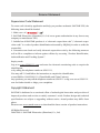
Solemn Statement
Supervision Code Statement
To ensure safe electricity application and help you purchase authentic SANTAK UPS, the
following items should be heeded:
1.Make sure of
2.SANTAK Electronics (Shenzhen) Co. Ltd. never grants authorization in any form to any
company to manufacture UPS;
3.Labelled on all SANTAK products is a “electronic supervision code” (“electronic supervision code” is a code of product identification advocated by SIQSAQ in order to strike the
counterfeit).
4.Consumers can check and verify electronic supervision code by the following means as
well as file a complaint or inform against offense by accessing “Product Identification,
Authentification and Tracking System”.
Inquiry mode:
Log on to www.95001111.com and enter the electronic monitoring code to enquire the
identification,
or by calling the telephone number at 95001111,
You may call 114 and follow the instructions to enquire the identification,
or send SMS to 106695001111 (China Mobile and China Unicom).
Any questions, you may call the telephone number at 95001111 or log on to www.95001111.
com for further details or lodge your complaints.
Copyright Statement
SANTAK is dedicated to a continued effort of technological innovation and provision of
improved products and services to satisfy customers’ needs. Product design and technical
specifications are subject to upgrading without notice. Actual product may differ from
photo.
Please access www.santak.com.cn to download the latest version of product instructions.
All Rights Reserved
2006-2008 © SANTAK Electronics (Shenzhen) Co., Ltd.
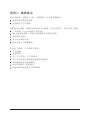
Safety Instructions
Operation Safety
1.Prior to the application, please read “Safety Instructions” carefully to ensure correct and
safe application. Please keep the user manual properly.
2.During operation, attention should be paid to all warning symbols and operations should
be followed strictly as required.
3.Equipment is not supposed to be used in environment that directly exposed to the sunlight
or raindrops or in humid.
4.The equipment should not be installed close to area of thermal sources or any area where
there is presence of devices such as electric heaters and furnaces.
5.Make sure the safety space should be left for proper ventilation when placing UPS. Refer
to the instructions during installation.
6.Dry items should be used for cleaning.
7.In case of a fire hazard, dry powder extinguisher should be used properly. Using liquid fire
extinguisher may result in electric shock hazard.
8.Storey bearing capacity of machine and batteries should be taken into consideration prior
to installation.
Electric Safety
1.Before electricity is switched on, make sure earthing is properly done and wire and battery
polarity are correctly connected.
2.When UPS relocation or wire reconnection is necessary, AC should be switched off and
UPS should be completely turned off, otherwise there might be a danger of electric shock
because output terminal might be still electrified.
3.Please use SANTAK specified appendix devices and accessories.
Battery Safety
1.Battery service lifetime will be shortened as ambient temperature rises. Replace batteries
periodically to guarantee normal UPS performance and sufficient back-up time.
2.Only personnel with proper expertise can carry out the maintenance of accumulator
batteries.
3.Replacement of accumulator batteries requires a match of same type and model with equal
quantity.
4.As accumulator batteries may contain potential eletric shock and short-circuit current
danger, to avoid accidents that might be thus resulted, the following warnings should be
observed during battery replacement:
A.Do not wear watches, rings or similar metallic items;
B.Use insulated tools;
C.Put on rubber shoes and gloves;
D.Do not place metallic tools or similar metallic parts on the batteries;
E.Switch off load connected to the batteries before dismantling battery connection terminals.
5.Do not expose accumulator battery to fire in order to avoid possible explosion that might
endanger physical safety.
6.Non-professionals are not allowed to open or destroy accumulator batteries for electrolytes in batteries contain strong acid and other dangerous substances which will cause damages to both human skins and eyes. Should electrolytes come into any contact with human
body unintentionally, rinse with clean water and seek medical advice.
7.Do not cause battery positive and negative polarity short circuit otherwise electric shock
or inflammation may occur.
Maintenance
1.Working environment and storage means can affect the service term and reliability of this
product to some extent. Therefore, the product is not suitable for performance in the following environment:
Locations where temperature exceeds the maximum or goes below the minimum temperature
as required by technical specifications or humidity is improper (temperature range: 040
; relative humidity range: 20%90%).
Locations where vibration and collision are constant;
Locations where metallic dusts, corrosive substances as well as salts and inflammable gases
are present.
2.For long-term inaction, UPS (without batteries) should be kept in dry environment with
temperature ranging from -25+55. Before start-up, ambient temperature should be
brought back to 0 or above for a certain period of time.
Contents
01
Chapter 1 Brief introduction---------------------------------------1.1 Product introduction-------------------------------------------------- 01
1.2 Frequently used symbols---------------------------------------------- 01
02
1.3 Product standard------------------------------------------------------1.4 Technical parameters and specifications------------------------------------03
1.5 Telephone hotline----------------------------------------------------- 04
Chapter 2 Exterior appearance----------------------------------- 05
05
2.1 Unpacking inspection---------------------------------------------------2.2 Outside view drawing------------------------------------------------- 06
2.3 Panel instructions----------------------------------------------------- 08
Chapter 3 Installation instructions---------------------------------10
3.1 Single machine installation---------------------------------------------- 10
3.2Parallel machine installation--------------------------------------------- 12
3.3 Procedures of connecting battery box to UPS------------------------------- 13
Chapter 4 Operation------------------------------------------- 14
4.1 Single machine operation------------------------------------------------14
4.2 Parallel machine operation---------------------------------------------- 21
Chapter 5 Communication interface------------------------------- 23
Chapter 6 Transportation, maintenance and troubleshooting----------- 26
Appendix 1 Light reference table----------------------------------28
29
Appendix 2 Warranty--------------------------------------------
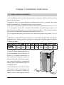
Chapter 1 Brief introduction
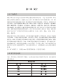
1.1 Product introduction
Castle EX Series products are high-efficiency and high-performance, double conversion,
pure-online and three phase input and three phase output UPS, with unit capacity ranging
between 20KVA-40KVA. Categorized by capacity, the products can be further divided into
3C3 EX 20KS/3C3 EX 20KS-ISO, 3C3 EX 30KS/3C3 EX 30KS-ISO and 3C3 EX 40KS/
3C3 EX 40KS-ISO. This series not only provides perfect solution for power source protection and successfully solves problems such as blackout, boost, brownouts, sags, decaying,
oscillation, high voltage impulse, voltage fluctuations, surges, harmonic distortion, disturbances,
frequency fluctuation etc, but also enhances adaptability to complicated working environments so that the application fields is well extended to computer equipments, communication equipments and other controlling equipments with good adaptability to complicated
industrial environments as well. Therefore, Castle EX Series products can be applied in a
diversified multi-industries field such as telecommunications, financing, transportation,
government, manufacturing and energy sectors.
Castle EX Series products are also capable of ECO mode. Under ECO mode, UPS is powered
by AC supply while in case of abnormal AC supply UPS will be supplied by accumulator
battery after conversion through inverter. As the energy conversion efficiency reaches as high
as 98% under ECO mode when there is normal AC supply, the energy saving effect of UPS
is remarkable. Meanwhile, when UPS inverter is at start-up mode but without power output,
which is similar to hibernation mode, the inverter life term can be largely extended. At normal
AC supply, except that ECO mode displays a relatively poorer power delivery quality
compared to normal double conversion mode, it is capable of satisfying the needs of most
power-driven equipments in today’s AC network incorporation.
Remark: under ECO mode, conversion time of 0ms mode is not guaranteed and it is applicable only to single machine.
1.2 Frequently used symbols
The following symbols will be frequently used in this User Manual as well as in the process
of actual application, therefore, correct identification and understanding of their connotations prove necessary.
1
Remark: Proper attention should be given to all warning symbols on the equipment and no
tearing or damaging of these symbols is allowed.
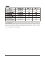
1.3 Product standard
Castle EX Series products are up to the following safety standards:
Castle EX Series products are up to the following level of EMC requirement:
2
WARNING:This is a product for commercial and industrial application in the second environment-installation restricitions or additional measures may be needed to prevent disturbances
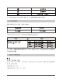
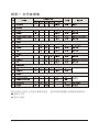
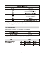
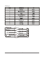
1.4 Technical parameters and specifications
Input
Wire connection: three phase four wire +grounded
Voltage: 380 ×(1 +25% / -45%)VAC (when input voltage<75%, output power derating is
required)
Frequency: 40Hz-70Hz
Power factor: over 0.99
Bypass voltage range: 380(1± 15%)
Output
Wire connection: three phase four wire + grounded
Voltage: 380 ×(1 ± 1%) VAC or 220 ×(1 ± 1%) VAC (with balanced load)
Power factor: 0.8
Frequency error: ± 8% at 50Hz (track bypass frequency input; when frequency exceeds
±8% or under the mode of battery power supply, frequency output should be ± 0.1% of the
rated amount.)
Overload time: exceed 10min (110% load 125%)
exceed 1min (125% load 150%)
Unbalanced load capacity: 100%
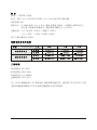
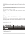
Battery voltage and charging voltage
Operating environment
Ambient temperature: 0 -40
Ambient humidity: 20%-90 %
3
Altitude: below 1000m
Storage temperature: -25-55
Remark: when UPS has been stored under a temperature of 0 or has been inactive for a
long time, it is suggested that prior to start-up of UPS environmental temperature should be
brought back to 0 or above for 2 hours.
General specifications
1.5 Telephone hotline
If you have any questions, please call SANTAK toll-free hotline by dialing 4008303938 or
8008303938 and our professional technical personnel will provide 24-hour hotline service
for you.
4
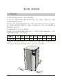
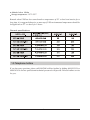
Chapter 2 Exterior appearance
2.1 Unpacking inspection
1.Unpack and there should be:
Winpower disc
User Manual
2. Check whether UPS is damaged during the process of transportation or not. Should any
damage be observed or parts be found missing, do not start the machine. Forwarder and
distributor should be immediately advised.
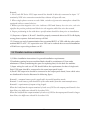
Remark: prior to transportation make sure of the height of the door and other obstacles
standing in the passage. Refer to the following figure for the dismantling of machine cabinet:
5
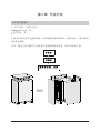
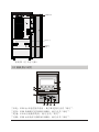
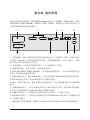
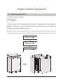
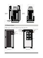
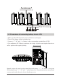
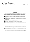
2.2 Exterior figure
Exterior figure of 3C3 EX 20KS/3C3 EX 20KS-ISO UPS
LCD panel
EXT.BATTERYTEMPPROBE
SERVICE
AS400
EPO
RS485
RS232
PARALLEL
intelligent slot
Extended slot
Button
LED indicator
light
Fan
Front view
Rear view
6
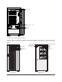
CHGR FAN
Maintenance switch
Main Main Front view (without front panel)
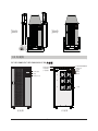
Exterior figure of 3C3 EX 30KS/3C3 EX 30KS-ISO,3C3 EX 40KS/3C3 EX 40KS-ISO
UPS
LCD panel
EXT.BATTERYTEMPPROBE
RS232
AS400
EPO
RS485
SERVICE
PARALLEL
intelligent slot
Extended slot
Button
LED indicator
light
FAN
Front view
Rear view
7
CHGR FAN
Maintenance switch
Main Main Front view (without front panel)
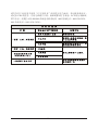
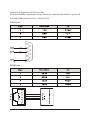
2.3 Panel instructions
AC: this light and inverter light will turn “green” when UPS is powered directly by AC;
Inverter: this light will turn “green” when UPS is loaded through the inverter;
Battery: this light will turn “yellow” when UPS is powered by batteries;
Bypass: this light will turn “green” when UPS is power loaded by AC through bypass.
8
Fault: this light will turn and stay “red” with continuous warning tone being given off in
case of UPS abnormal function; or flash “red” with intermittent warning tone being given off.
LCD: display UPS condition.
:Confirm/Enter; press this button to select a menu or confirm an operation.
:PageDown; press this button to switch to next screen display under the same menu.
:PageUp; press this button to return to next screen display under the same menu.
EscEscape; press this button to return to previous menu or cancel a certain operation.
Remark: Refer to Appendix 1 for detailed information of LED in accordance with UPS
condition.
9
Chapter 3 Installation instructions
3.1 Single machine installation
1) The installation of this unit must be performed in compliance with the electrical code by
professional personnel.
2) Install the UPS in a clean and stable environment that is free of vibration, dust, high
humidity, flammable gas, flammable liquid or caustic substance.
3) To ensure normal UPS performance, ambient temperature should range between 0-40
. If temperature exceeds 40, maximum load should be decreased progressively by 12%
of the rated amount along with every increase of temperature by 5. The maximum ambient
temperature for normal UPS performance should not exceed 50.
4) It is suggested that battery pack should work within a temperature range from15 to 25
.
5) Altitude for normal UPS function should not exceed 1000m. Should UPS be intended for
application above 1000m, progressive decrease of rated output should be applied as listed in
the following chart:
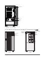
6) Castle EX Series adopt forced fan cooling and installation spot should make allowance for ventilation. Meanwhile, inside maintenance should be carried out
from the front side and therefore maintenance space should also be considered in
advance. Refer to the following figure for
installation space.
7) External batteries of Castle EX Series
UPS require serial connection of two
groups of 14-16 batteries (12VDC per
battery) with the same capacity, nominal
10
voltage for each group being168VDC-192VDC. Battery capacity and number of group can
be selected at your option. Battery pack must be equipped with DC switch (it is suggested
that selection of DC switch should be in line with installation drawing for wire connection).
8) Brake pad: use wrench 19# in clockwise direction so as to screw the brake
pad down to the ground, keeping the machine from moving.
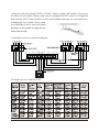
9) Installation and wire connection diagram
10) Jumper list for Castle EX UPS
11
Remark:
1. For Castle EX Series UPS, input neural line should be directly connected to input “N”
terminal of UPS wire connection terminal bay without AC input idle-run;
2. When single-phase current exceeds 100A, switches of protective atmosphere should be
equipped with arc control devices;
3. Battery positive/negative wire size: indicates UPS and battery box wire size; red wire
signifies the positive polarity and black wire the negative,while blue wire the neutral.
4. Proper positioning in line with above specifications should be done prior to installation.
11) Sequence of phase A, B and C should be properly connected otherwise UPS will display
wrong phase sequence fault and start-up will fail.
12) Connect one end of communication line to terminal RS232 of UPS while the other end to
terminal RS232 of PC. PC supervision over UPS can be realized after successful installation
of WinPower supervising software on PC.
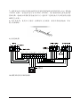
3.2 Parallel machine installation
1) Follow installation instructions for general installation requirements.
2)Ventilation spacing between machine flanks should be a minimum of 10cm and a
minimum of 50cm (considering the space for replacing fans) for the back for machine.
3) Input wiring for each set of UPS should follow the requirements for that of single unit.
Each UPS input should be connected to the same input patch board.
4) Each UPS output wire should be connected to the output patch board, from which wires
are distributed for load as illustrated in following figure.
Remark 1: common battery pack is applicable in parallel machine mode;
Remark 2: each battery pack should be of the same model from the same manufacturer;
Remark 3: requirement of output wiring length:
When the lead from the output terminal of each set of UPS to the output patch board is less
than 20m, wire difference should be less than 20%;
When the lead from the output terminal of each set of UPS to the output patch board is longer
than 20m, wire difference should be less than 10%.
12
3.3 Procedures of connecting battery box to UPS
1. Make sure that UPS input and output terminals are uncharged;
2. Turn off the battery switch on battery box;
3. Connect “+”, “N” and “-“ of battery to the corresponding terminal bay of UPS;
4. Use multimeter (DC Voltage) to measure the voltage of positive and negative batteries as
well as positive and negative polarity.
Remark: remove the panel on the terminal bay and connect “+”, “N” and “-” wires from
UPS terminal bay to “+”, “N” and “-” of the battery box. Non-professionals are not allowed
to carry out the task otherwise electric shock may occur.
13
Chapter 4 Operation
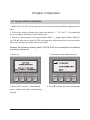
4.1 Single machine operation
1. Make sure A, B and C phase sequences are correctly connected and then supply power to
UPS.
2. Turn on the switch on battery box (make sure that the “+”, “N” and “-” of terminal bay
are in accordance with those on the battery box).
3. Switch on “input breaker” (Line input breaker: Main ; bypass input breaker: Main )
on UPS and fans start to rotate for UPS self-inspection. Main menu can be accessed within
about 4sec and then operations should be carried.
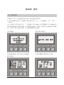
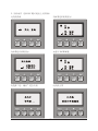
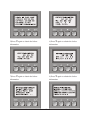
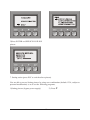
Remark: the following drawing takes 3C3 EX 20KS as an example and statistics
are only for reference.
1)Power on
2)Automatic access within about 4s
4)Press to obtain the below information
3)Press ESC to access or automatically
access within 1min with no button being
pressed
14
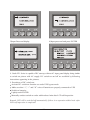
5)Press again to obtain the below
6)Press again to obtain the below
information
information
7)Press again to obtain the below
8)Press again to obtain the below
information
information
15
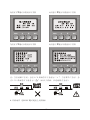
Remark: when malfunction occurs, “x” will appear at the lower right corner of the picture
while when warning occurs “
” will appear at the same position (as illustrated in the below
picture with battery mode as an example).
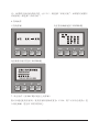
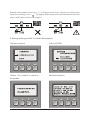
4. Start-up action (press ESC to exit the above picture)
1)Switch-on picture
2)Press ENTER
3)Select “Yes, Confirm” to switch on
4)Normal Switch-on
the machine
16
5)Battery power supply (switch off line input breaker)
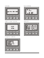
5. Switch-off action (press ESC to exit above picture)
1)Switch-off picture
2)If it is in single machine mode, the
following will appear
3)If it is in parallel machine mode, the
4)Press ENTER
following will appear
17
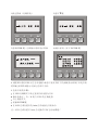
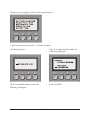
5)Select “Yes, Confirm” to switch off
6)Normal Switch-off
the machine
Remark: If you intend to switch off only one set of UPS among the parallel machine system,
select “single machine switch-off”; if switch-off is intended for the entire parallel machine
system, select “parallel machine switch-off”.
6. Help
1)Help picture
2)Press ENTER on help picture
18
3)Press ENTER on SERVICE HOTLINE
picture
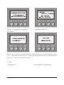
7. Setting action (press ESC to exit the above picture)
You are able to access Setting picture by using user combination (default: 1234, subject to
personal modification) so as to set the following programs.
2) Press 1)Setting picture (bypass power supply)
19
3)Input Password display
4)Input password and press ENTER
8. Castle EX Series is capable of DC start-up without AC input, panel display being similar
to switch-on picture with AC supply. DC switch-on and off are available by following
instructions appearing in the pictures.
9. Procedures of DC switch-on:
Activate DC switch-on function set under UPS bypass mode
Make sure that “+”, “-” and “N” wires of batteries are properly connected to UPS
Switch on batteries
Lightly touch ENTER
Manually conduct switch-on order within about 1min after LCD self-inspection
Remark: UPS will be switched off automatically if there is no operation within 1min after
LCD self-inspection is completed!
20
4.2 Parallel machine operation
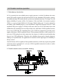
1. Redundancy introduction
N+X is currently the most reliable power supply structure, in which N indicates the minimum UPS number required for the total load and X is the redundant UPS number, namely,
the malfunctioning UPS number that the system can simultaneously bear. The larger X is, the
higher reliability of system will be. For instance, if the total load of a customer registers
55kVA, we can use Castle 20KS for N+X design. With N taking up 3, X can be selected in
accordance with reliability degree or cost requirement. Supposing customer selects X=2 and
equalized UPS power supply is 11kVA for each unit, when one set of UPS breaks down with
malfunction, the remaining four sets will provide power with almost 14kVA equalized current;
if two sets of UPS fail, the remaining three sets of UPS are supposed to provide power
supply with almost 18kVA equalized current. The maximum allowance of this system is for
two sets of UPS going down at the same time, the chances of which are much smaller than
those of one UPS malfunction. Therefore, the reliability degree can be largely enhanced,
making it an optimal mode for application in locations where high degree of reliability is
always a focus.
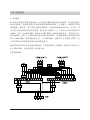
Castle EX Series UPS is capable of direct parallel connection, which only requires the parallel
connection wires (optional) for 2 to 8 sets of UPS in parallel connection in order to realize
power redundancy (N+X).
2. Parallel machine wire connection drawing
21
3. Operation instructions
1)Follow single machine operation instructions for general operation.
2)After switch to Line mode, all machines will jump to conversion mode; switch off: when
switch-off is conducted under conversion mode, all machines will simultaneously switch off
inverter and then convert to the bypass mode after the last machine completes switch-off
action.
22
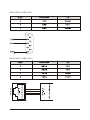
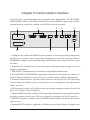
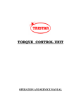
Chapter 5 Communication Interface
Castle EX Series provide Intelligent Slot, Expanded Slot, PARALLEL, EXT.BATTERY
TEMP PROBE, AS400, EPO, RS485 and RS232 as well as SERVICE Supervising Communication Interface exclusively available to SANTAK technical personnel.
1
3
PARALLEL
PARALLEL
E X T . B AT T E R Y
TE MP PRO BE
5
6
AS400
EPO
8
RS485
SERVICE
Intelligent slot
RS232
Expanded slot
2
4
7
9
1. Intelligent slot: suitable for WebPower card (optional) of remote supervising management,
enabling you to realize remote supervising management on UPS by accessing Internet.
(Intelligent slot adapter card is divided into long card and short card; Castle EX Series require
the latter.)
2. Expanded slot: available only to users with special requirements and not open to those of
standard configuration.
3. PARALLEL: communication wire interface under parallel machine mode.
4. EXT.BATTERY TEMP PROBE: temperature interface for external battery cabinet, capable of battery temperature supervision so as to realize battery intelligent management.
5. Standard AS400 interface: provides AS400 and users can directly use UPS supervising
function offered by AS400 system to realize power source management (See Appendix for
AS400 port Pin).
6. EPO: emergency power off, which provides users having emergency switch-off need with
direct UPS output switch-off function.
7. Standard RS485 Interface: capable of UPS supervising management when parallel machine,
providing complete control over UPS power supply (See Appendix for RS485 port Pin ).
8. SERVICE Interface: available only to SANTAK internal technical professionals and not
open to users.
9. Standard RS232 Interface: applicable to WinPower supervising software of graphic man
23
agement (See Appendix for RS232 port Pin).
For more information regarding the usage of the above communication interfaces, please call
SANTAK Hotline 400-830-3938 or 800-830-3938.
RS232 port:
RS485 port:
24
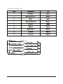
AS400 port:
25
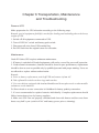
Chapter 6 Transportation, Maintenance
and Troubleshooting
Remove UPS
Make preparation for UPS relocation according to the following steps.
Remark: special equipment (forklift) is needed for loading and unloading due to the heavy
weight of UPS.
1. Switch off all equipments connected to UPS.
2. Turn off UPS AC switch and battery pack switch.
3. Disconnect all wires from UPS terminal bay.
4. Put UPS back into the original carton for relocation.
Maintenance
Castle EX Series UPS requires minimum maintenance.
1. If battery is switched off, loaded equipments will not be covered for power-off protection.
2. Under normal circumstance, batteries should be found in poor performance, replacement
should be done as soon as possible only by qualified personal with proper training. Users are
not allowed to replace without authorization.
Remark:
A. Prior to battery replacement, switch off UPS and remove it from AC.
B. Take off metallic articles such as rings and watches.
C. Use screw drivers equipped with insulated handles and do not place tools or other metallic
substances on the batteries.
D. Short circuit or reverse connection is forbidden for battery polarity connection.
3. It’s not recommended to replace batteries individually. Complete replacement should
follow instructions given by battery suppliers.
4. Make sure UPS vent are properly ventilated and clean side frames and fan vents from
dusts every half a year (switch off AC and battery power prior to cleaning).
26
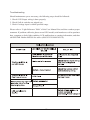
Troubleshooting
Should maintenance prove necessary, the following steps should be followed:
1. Check if UPS input wiring is done properly.
2. Check if all air switches are tripped out.
3. Check if voltage input is within specified range.
Please refer to “Light Reference Table” of this User Manual first and then conduct proper
treatment. If problems still exist, please record UPS model, serial number as well as purchase
date, symptom on fault, light condition, LCD malfunction or warning information, and then
call SANTAK Hotline 400/800 for advice (4008303938/8008303938).
27
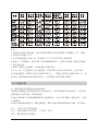
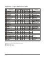
Appendix 1 Light Reference Table
Should any display or warning message excluded in the above table be found, please contact
distributor or call SANTAK Hotline for advice.
Indicator light is on
Indicator light flashes
28
Appendix 2 Warranty
SANTAK its products to be offered free warranty service for three years from the date of
purchase.
To obtain service under warranty via an valid guarantee offered by dealers;
To obtain service under warranty via serial number.
As a user of SANTAK, if your UPS fails, please contact our 400/800 hotline for the following service:
Three-year warranty (covering batteries purchased from SANTAK);
24-hour toll-free helpline (See the hot line number at the warning label located on the
cabinet cover);
Nationwide warranty;
Technical support on our web site;
Toll-free on-site service
This limited warranty does not apply to conditions as follows:
Man-made fault;
Out of warranty;
The finished product of which the serial number is changed or lost;
Damage or loss resulted from force majeure or external causes;
Disassembly or modifications to the unit with no authorization;
Disobeying provisions of operating/using the unit;
Battery over discharged or man-made damage.
29
614-06719-03
http://www.sunear.net