1
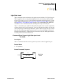
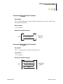
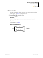
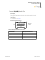
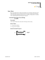
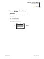
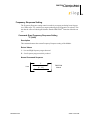
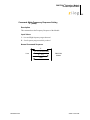
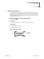
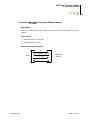
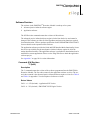
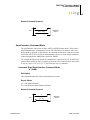
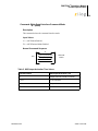
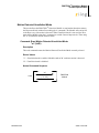
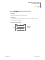
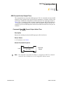
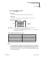
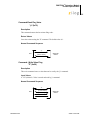
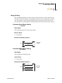
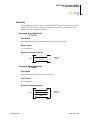
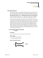
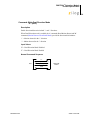
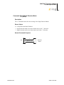
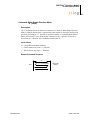
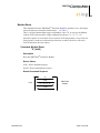
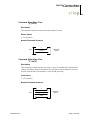
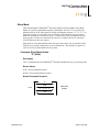
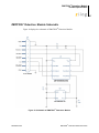
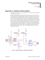
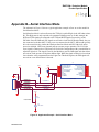
ZMOTION™ Detection Module Product Specification 16 Light Gate Level These commands control and monitor the signal associated with the LG (Light Gate) pin. This is typically relative to the ambient light detected by an externally connected CDS photocell. The range is 0 to 255, with 0 indicating maximum ambient light and, 255 indicating minimum ambient light. See Appendix A—Hardware Interface Mode on page 52 and Appendix B—Serial Interface Mode on page 53 for recommended CDS Photo Cell connections. The 'b' command reads the current signal level present on the pin. The "L" command sets the Light Gate Threshold value. This value is used in conjunction with the signal on the LG pin to internally "Gate" the /MD signal such that it does not activate in the presence of ambient light. When the signal on the LG (Light Gate) pin is below this value, the /MD output signal remains inactive even when motion has been detected. When the signal on the LG (Light Gate) pin is above this value, the /MD signal activates normally when motion has been detected. Command: Read Current Light Gate Input Level "b" (0x62) Description The "b" command returns the current signal level present on the LG (Light Gate) pin. Return Values 0 - 255 (decimal) Normal Command Sequence “b” Host PS028405-1010 [0 – 255] ZMOTION Module Serial Commands