1
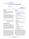
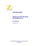
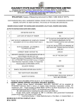
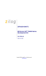
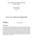
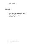
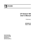
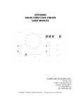
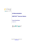
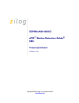
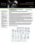
Application Note
Z8 Encore! XP®-Based NiCd Battery
Charger
AN022103-0608
Abstract
This Application Note describes Zilog’s Z8
Encore! XP®-based Nickel Cadmium (NiCd) battery charger. The battery charger application uses
the internal clock of the Z8 Encore! XP microcontrollers unit (MCU) as the system clock. An internal reference voltage of 2 V is applied to the ADC
peripheral of the Z8 Encore! XP MCU.
Note: The source code file associated with
this Application Note, AN0221SC01.zip, is available on
www.zilog.com.
Z8 Encore! XP 4K Series Flash
Microcontrollers
Zilog’s Z8 Encore!® products are based on the new
eZ8™ CPU and introduce Flash memory to Zilog’s
extensive line of 8-bit MCU. Flash memory
in-circuit programming capability allows faster
development time and program changes in the
field. The high-performance register-to-register
based architecture of the eZ8 core maintains backward compatibility with Zilog’s popular Z8®
MCU. Z8 Encore! MCUs combine a 20 MHz core
with Flash memory, linear-register SRAM, and an
extensive array of on-chip peripherals.
The Z8 Encore! XP 4K Series of devices support
up to 4 KB of Flash program memory and 1 KB
register RAM. An on-chip temperature sensor
allows temperature measurement over a range of
40 ºC to +105 ºC. These devices include two
enhanced 16-bit timer blocks featuring Pulse Width
Modulation (PWM), Capture and Compare
capabilities. An on-chip Internal Precision Oscillator (5 MHz/32 KHz) is used as a trimmable clock
source requiring no external components. The Z8
Encore! XP devices include 128 bytes of Non
Volatile Data Storage (NVDS) memory where individual bytes are written or read. The full-duplex
UART, provides serial communications, Infrared
Data Association (IrDA) encoding and decoding
capability, and supports multidrop address processing in hardware.
The on-chip peripherals make the Z8 Encore! XP
MCUs suitable for a variety of applications including motor control, security systems, home appliances, personal electronic devices, and sensors.
Discussion
This section discusses the functionality of the Z8
Encore! XP-based battery charger application in
detail. For detailed information about NiCd battery
technology, see Appendix D—Battery Technology
on page 14.
Theory of Operation
At the core of a battery charger is the DC–DC converter (also known as a buck converter) that acts as
a regulated power source. The charger hardware is
capable of regulating the charger output in a number of modes, such as constant voltage, constant
current, or constant voltage with a current limit.
The charger is a control system in itself. The type
and capacity of the battery determines the mode of
operation of the battery controller—namely, a constant current source or a constant voltage source.
The voltage (VSET) and current (ISET) set points
are also determined by the type and capacity of the
battery.
The parameters, current and voltage, are controlled
using the PWM technique. In the PWM technique,
the frequency of the signal is maintained constant,
Copyright ©2008 by Zilog®, Inc. All rights reserved.
www.zilog.com
Z8 Encore! XP®-Based NiCd Battery Charger
and the width of the pulse or the duty cycle of the
signal is varied. This variation is reflected as a
change in voltage and/or current at the output. The
switching regulator reads the parameters through a
feedback circuit, and the battery controller operates
based on the control algorithm.
The PWM output is obtained by comparing the
actual value of the parameter under control with
the corresponding set point. In the constant voltage
mode, the converter voltage is compared with the
voltage set point. In contrast, in the constant current mode, the voltage developed by the charging
current across a sense resistor is compared with the
current set point. The feedback loop maintains the
converter voltage or the converter current constant
depending on the selected mode of operation.
Controllers are differentiated based on the method
of regulation of parameters in accordance with the
corresponding set points. For detailed information
about battery controllers, see the related document
provided under the Electronics topic in References
on page 6. In a proportional controller, the actual
value and the set value are compared, and the
resulting error value is used. The drawback of a
proportional controller is the possibility of a steady
state error. Adding an integral component to the
control algorithm eliminates this error.
The equation for a proportional plus integral (PI)
controller is:
x ( t ) = ( k1 × e ( t ) + k2 × ∫ e ( t ) dt )
To be useful for a microcontroller-based (discrete)
system, the integral is approximated by a running
sum of the error signal. Therefore, an equation in
the differential form is expressed as follows in
Equation 1:
Equation 1 is the position algorithm. A better representation of Equation 1 is explained in Equation
2, as follows:
k=2
⎛
⎞
U [ k – 1 ] = ⎜ C1 × e [ k – 1 ] + C2 × ∑ e [ j ]⎟
⎝
⎠
j=0
Subtracting Equation 2 from Equation 1 and rearranging the terms yields Equation 3, as follows:
u [ k ] – u [ k – 1 ] = ( Kp × e [ k ] + Ki × e [ k – 1 ] )
Where, Kp and Ki are the proportional and integral
constants, respectively.
Equation 3 is the velocity algorithm, and is a convenient expression as only the incremental change
in the manipulated variable is calculated.
The charging algorithms are designed based on the
type of battery and the current state of charge for
that battery. The basic charging methods are
constant current and constant voltage charging.
The NiCd and Nickel Metal Hydride (NiMH)
batteries are charged using the constant current
method.
In the constant current mode, fast charging occurs
when the charging current equals the rated battery
capacity, C. Fast charging requires constant monitoring of battery parameters and precise termination techniques. It is therefore important to know
when to terminate charging. In the NiCd battery
charger application, the battery parameters are constantly monitored, and the negative Δ V termination technique is used. As a result, the NiCd
battery charger ensures the safety of the battery.
For detailed information about termination techniques associated with NiCd batteries, see Appendix D—Battery Technology on page 14.
k=1
⎛
⎞
u [ k ] = ⎜ C1 × e [ k ] + C2 × ∑ e [ j ]⎟
⎝
⎠
j=0
Where, C1 and C2 are constants.
AN022103-0608
Page 2 of 15
Z8 Encore! XP®-Based NiCd Battery Charger
Developing the Application
with the Z8 Encore! XP MCU
This section provides an overview of the functional
architecture of the NiCd battery charger implementation using the Z8 Encore! XP MCU.
Hardware Architecture
Figure 1 displays a hardware block diagram for the
battery charger application. The Z8 Encore! XPbased NiCd battery charger application features the
following hardware blocks:
•
Z8 Encore! XP Development Board
•
External power source (32 V, 3 A)
•
Step-down DC–DC (buck) converter
•
Feedback section (analog design)
•
NiCd battery
Power Section
The step-down DC–DC (buck) converter provides
a voltage or current appropriate to the NiCd battery. The buck converter modulates a higher voltage (from the external source) with a varying pulse
width (PWM method) to generate a lower voltage.
The pulse width is controlled by the control algorithm based on the values obtained from the feedback section.
The feedback section consists of four differential
amplifiers/attenuators. The parameters controlled
by the first three amplifiers are the converter voltage (VOUT), the battery voltage (VBATT), and the
battery current (IBATT). The battery current and the
converter current are same. The fourth differential
amplifier is used for temperature measurement in
the case of batteries featuring built-in temperature
sensors.
External
Power Source
(32 V, 3 A)
+
Step-Down DC-DC (buck)
Converter
Battery
PWM Output
derived from the internal precision oscillator of the
Z8 Encore! XP MCU. The reference voltage
required for the ADC is generated internally by the
Z8 Encore! XP MCU, hence the external component requirement and the Bill of Material (BOM)
cost is reduced.
Z8 Encore! XP
Development Board
For schematic diagrams associated with the battery
charger application, see Appendix B—Schematics
on page 8.
Software Implementation
ADC ch0
ADC ch1
ADC ch2
ADC ch3
Feedback Section
Output Voltage
Battery Voltage
Battery Current
Battery Temperature
-
Figure 1. Block Diagram of Battery Charger
Hardware
The battery charger application uses Port B on the
Z8 Encore! XP MCU as ADC inputs. Timer 1 is
used in PWM mode and the output is tapped at the
PC1/Timer 1 output pin. The system clock is
AN022103-0608
All Z8 Encore! XP peripherals are initialized from
their power-on state to the required mode of operation. After initialization, the battery parameters are
loaded into the variables. These battery parameters
are defined in the charger.h header file.
The safety and termination thresholds are calculated based on the battery parameters. The set
points for the DC-DC step-down (buck) converter
voltage, the current, and the current limit are calculated. After these one-time calculations are complete, the charger software enters into an infinite
loop, which is broken only by a successful charge
completion or a safety error.
Page 3 of 15
Z8 Encore! XP®-Based NiCd Battery Charger
Inside the infinite loop, the ADC reads the actual
values for the converter output voltage, the battery
voltage, the current, and the temperature (temperature is measured only if the battery features a temperature sensor). The ADC measures the output
voltage and the output current of the DC–DC converter as feedback to the controller. The ADC also
measures the voltage at the battery terminals as an
input to determine the charge termination. Measurement of the output voltage, the output current,
and the battery voltage are the basic measurements.
The current across the battery terminals is same as
the measured converter output current. For batteries featuring built-in temperature sensors, the
charger reads the battery temperature in addition to
the basic measurements. The temperature measurement is significant from the safety point of view.
After the actual values (VOUT, VBATT, and IBATT)
are determined, they are checked for safety limit
compliance. The safety routine is responsible for
the overall safety features associated with the battery charger. The charger ensures safety by comparing the actual converter voltage, the battery
voltage, and the battery temperature with the calculated thresholds. Crossing these thresholds
switches off the PWM output, which turns off the
converter output and terminates charging functions. Such termination protects the batteries in the
case of a device failure.
If all the actual values are within limits, the battery
is tested for full charge. NiCd batteries are considered to be completely charged if the voltage level,
as indicated by Figure 2, produces a distinctive rise
over a period of time, then a decrease.
Voltage
Time
Figure 2. Voltage Levels as a Function of
Time
The dashed line in Figure 2 represents where a
decrease in voltage occurs. At this point, maximum
charge has been reached; charging then terminates.
If, however, the battery is not completely charged,
the duty cycle required for maintaining the setpoints at the converter output is calculated by a
control algorithm.
This control algorithm implements PI control to
derive a PWM output based on the equations presented in the Theory of Operation on page 1. The
timer ISR is invoked every 5 ms. The PWM value
computed by the control algorithm is loaded into
the PWM generators to be transmitted via the output pin. The 16-bit timer PWM mode offers a programmable switching frequency based on the
reload value. This flexibility allows you to trade off
between accuracy and frequency of the PWM
switching signal. A lower frequency results in a
higher reload value and a higher resolution in the
pulse width variation. The reverse is also true.The
timer ISR also updates the charge termination variables every 10 s.
For flowcharts related to the battery charger application, see Appendix C—Flowcharts on page 12.
AN022103-0608
Page 4 of 15
Z8 Encore! XP®-Based NiCd Battery Charger
Testing
Equipment Used
This section discusses the setup, equipment used,
and procedure followed to test the Z8 Encore! XPbased NiCd battery charger application.
The equipment used to test the Z8 Encore! XPbased NiCd battery charger are listed in Table 1.
Table 1. Battery Charger Test Equipment
Setup
System Equipment
The test setup for the Z8 Encore! XP-based NiCd
battery charger application is described in Figure 3.
Z8 Encore! XP 4K Series (Z8F042A28100KIT)
Development Kit
External power supply
Test Equipment
External DC Power Supply
Oscilloscope
Z8 Encore! XP
Development Board
PWM
DC-DC Step-Down Converter
Make: Aplab, Model: LQ
6324
Oscilloscope
Make: Tektronix, Model: TDS
724D; 500 MHz / 1 GSps
Multimeter
Make: Motwane,
DM3750
Battery
Model:
Batteries Used for Testing
Feedback Attenuators
Charger Hardware/External Circuitry
Figure 3. Battery Charger Test Setup
The test setup comprises of a Z8 Encore! XP
Z8F042A Development Board, a NiCd battery that
must be charged, an oscilloscope, an external DC
power supply, and a DC-DC step-down (buck) converter. A feedback circuit comprised of differential
amplifiers or attenuators also forms a part of the
test setup.
The external DC power supply provides two different voltages to the charger circuits—the DC–DC
step-down converter and the feedback attenuators.
The operational amplifier-based feedback attenuator circuits are fed with a 12 V supply. The DC–DC
converter works on a 8 V to 12 V DC input for the
batteries tested. The control algorithm provides the
necessary line regulation to sustain the voltage
variation at the input.
BP–T16
Make: Sony, Type: NiCd,
Ratings: 3.6 V, 270 mAh
Procedure
To test the Z8 Encore! XP-based NiCd battery
charger application, perform the following steps:
1. Download the AN0221-SC01.zip file from
www.zilog.com. Extract its contents to a folder
on your PC.
2. Launch ZDS II for Z8 Encore!.
3. Make the hardware connections as described in
Figure 3 and the schematics provided in
Appendix B—Schematics on page 8.
4. Connect the battery to be charged across the
provided battery terminals (see Appendix B—
Schematics on page 8).
5. Apply the required voltages to the appropriate
circuits as described in the section Setup on
page 5.
6. Download the battery charger code to the Z8
Encore! XP Flash memory using ZDS II–IDE.
7. Execute the battery charger code.
AN022103-0608
Page 5 of 15
Z8 Encore! XP®-Based NiCd Battery Charger
8. Observe the PWM waveforms on the oscilloscope.
•
Digital Control Systems, Volume 1—Fundamentals, Deterministic Control; Author: Rolf Isermann, ISBN: 0-387-50266-1, Publisher:
Springer Verlag
•
Zilog Developer Studio II-Z8 Encore!® User
Manual (UM0130)
Results
The charging of the battery began in the constant
current mode with the charging current equal to 1
C. The charging is terminated when the battery
voltage increases to a peak and then decreases
(negative Δ V termination technique).
Summary
This Application Note discusses a NiCd battery
charger implementation using the Z8 Encore! XP
MCU. The battery charger software provides fast
charging algorithms. Fast recharge is possible due
to the accurate monitoring of the charging rendered
by the 10-bit accuracy of the ADC. Monitoring the
charging mechanism facilitates the accurate
termination of charging. Therefore, overcharging is
prevented, resulting in a longer battery life. Additionally, the PWM technique facilitates an accurate
DC-DC (buck) step-down converter implementation with excellent line/load regulation.
References
The documents associated with Z8 Encore! XP®,
eZ8™, and ZDS II available on www.zilog.com
and electronics references are provided below:
•
eZ8™ CPU User Manual (UM0128)
•
Z8 Encore! XP® F082A Series Product Specification (PS0228)
•
Z8 Encore! XP® F042A Series Development Kit
User Manual (UM0166)
•
Power Electronics Design Handbook: Low
Power Components and Applications; Author:
Nihal Kularatna, ISBN: 0-7506-7073-8,
Publisher: Oxford: Newnes, 1998
•
High Frequency Switching Power Supplies: Theory and Design; Author: George Chryssis, ISBN:
0-07-010949-4, Publisher: McGraw-Hill Book
Company
AN022103-0608
Page 6 of 15
Z8 Encore! XP®-Based NiCd Battery Charger
Appendix A—Glossary
Definitions for terms and abbreviations used in this Application Note that are not commonly used are listed
in Table 2.
Table 2. Glossary
Term/Abbreviation
Definition
1C
A charging current rate equal to the A-hr rating of the battery
ADC
Analog-to-Digital Converter
ISR
Interrupt Service Routine
Li-Ion
Lithium Ion
mAh
milli-Ampere-hour: the unit of battery capacity
NiCd
Nickel Cadmium
NiMH
Nickel Metal Hydride
PI
Proportional and Integral
PWM
Pulse Width Modulation
SLA
Sealed Lead Acid
AN022103-0608
Page 7 of 15
Z8 Encore! XP®-Based NiCd Battery Charger
Appendix B—Schematics
The schematics in Figure 4 displays the Z8 Encore! XP MCU pin diagram.
VDD
U5
VDD
6
VDD
PC0/ANA4/CINP/LED
9
VSS
PC1/ANA5/CINN/LED
24
PC2/ANA6/LED
25
PC3/COUT/LED
26
PC4/ LED
16
PC5/ LED
17
-RESET
21
~RESET / PD0
DBG
22
DBG
R7
560E
PA0/T0IN/~T0OUT/XIN
PC6 / LED
19
8
PA1/T0OUT/XOUT
PC7/ LED
20
PB0/ANA0/AMPOUT
27
PB0/ANA0
PB1/ANA1/AMPINN
28
PB1/ANA1
PB2/ANA2/AMPINP
1
PB2/ANA2
PB3/CLKIN/ANA3
4
PB3/ANA3
11
PA2/DE0
12
PA3/ ~CTS0
13
PA4/RXD0
14
PA5/TXD0
18
R8
560E
D4
LED
7
15
PWM
23
PB4/ANA7
2
PB5/VREF
3
ADD_VREF_2V5
(PB6) AVDD
5
AVDD
(PB7) AVSS
10
AVSS
PA6/ ~T1OUT/T1IN
PA7/ T1OUT
D5
LED
R9
560E
D6
LED
R10
560E
D7
LED
Z8F042A
Figure 4. Schematic Displaying the Z8 Encore! XP MCU Pin Diagram
AN022103-0608
Page 8 of 15
Z8 Encore! XP®-Based NiCd Battery Charger
The schematic diagram in Figure 5 displays the external circuitry for the battery charger application.
VDD
CONN JACK PWR
3
2
1
F1
U7
V IN
RXE050
+
J8
C15
C16
SENSE
-RESET
0.1uF
5
VIN
2
4
SENSE
SHDN
OUT
1
+
C12
100uF, 10V
LT1129-3.3/DD
C14
0.1uF
100uF, 10V
NOTE:
SENSE should be ’sense’d as close to
the processor as possible.
VDD
VDD
R30
10K
J8
VDD
1
3
5
C27
2
4
6
-RESET
DBG
-RESET
DBG
0.1uF
GND
CON6A
Figure 5. Schematic Displaying the External Circuitry for the Battery Charger Application
AN022103-0608
Page 9 of 15
Z8 Encore! XP®-Based NiCd Battery Charger
The schematic diagram in Figure 6 displays the DC-DC step-down (buck) converter.
VP30V
R3
1K
V_out(+)
R37
18E
V_out(-)
IRF9540
Q1
D2
R1
L1
Q2
2N2222
PWM
3.3K
120uH
MBR360
C1
C2
R4
470E
J1
R2
2.2K
D3
MBR360
100uF
R5
79E
100uF
D1
LED
V_batt(+)
1
2
V_batt(-)
Rsense
R6A
10E
R6B
10E
C3
0.1uF
CON2
I_out(+)
I_out(-)
NOTE:
For Testing the VP30V is obtained from
External Power Source.
Figure 6. Schematic Displaying the DC-DC Step-Down (Buck) Converter
AN022103-0608
Page 10 of 15
Z8 Encore! XP®-Based NiCd Battery Charger
The schematic diagram in Figure 7 displays the feedback circuits for the battery charger application.
0. 1uF
0. 1uF
VCC
C7
C7
R2 9
R1 7
1K
1K
R3 5
10K
R2 6
13
R2 7
12
V _ba tt(-)
14
R1 4
2
R1 5
3
V _batt(+)
R1 6
1K
AVDD 12V
AVDD 12V
A V DD12V
0. 1uF
0. 1uF
C7
C1 1
100u F
R22
I_out(-)
10K
10K
10
PB2 /ANA2
Battery Current
R2 4
1K
V _out(+)
R1 8
6
R1 9
5
AVDD 12 V
LM324
U1B
7
10K
4
1K
V _out(-)
R3 4
1K
11
LM324
U1C
8
I_out(+)
R2 1
9
R23
C7
C8
10uF
R2 0
1K
PB3 /ANA3
Converter Output Voltage
4
1K
C1 0
0. 1uF
C9
0. 1uF
1K
11
R2 5
PB1 /ANA1
Battery Voltage
10K
4
R2 8
1K
LM324
U1A
1
PB0 /ANA0
Battery Temperature
10K
T hermis tor
J6
11
10K
4
10K
1
2
LM324
U1D
11
V _ba tt(-)
AVDD 12V
NOTE:
For Testing the AVDD12V is obtained from
External Power Source.
Figure 7. Schematic Displaying the Feedback Circuits
AN022103-0608
Page 11 of 15
Z8 Encore! XP®-Based NiCd Battery Charger
Appendix C—Flowcharts
This appendix provides flowcharts for the battery charger application described in this document. Figure 8
explains a flowchart of the main routine for the battery charger application. The main routine involves
calculation of safety limits, thresholds, duty cycle, reading of feedback values for battery voltage, charging
current, and converter voltage.
Start
Initialize peripherals
Calculate safety limits and thresholds
for charging and termination
Read feedback values for battery voltage,
charging current, and converter voltage
Within safety limits?
No
Yes
Is the battery charged?
No
Yes
Terminate
Calculate the duty cycle
Figure 8. The Main Routine
AN022103-0608
Page 12 of 15
Z8 Encore! XP®-Based NiCd Battery Charger
Figure 9 presents a flowchart of the Interrupt Service Routine (ISR) for reloading the PWM value and
updating the charge termination data.
Start ISR
Reload PWM Value
Update charge termination data every 10 seconds
Return from ISR
Figure 9. The ISR Return Routine
AN022103-0608
Page 13 of 15
Z8 Encore! XP®-Based NiCd Battery Charger
Appendix D—Battery
Technology
The four mainstream battery chemistries (NiCd,
NiMH, SLA, and Li-Ion) feature different charging
and discharging characteristics. Long-term battery
life and performance are critically dependent up on
how batteries are charged. Therefore, it is important to charge batteries with a mechanism specific
to their requirements.
It is also important to know when to terminate
charging, because overcharging of a battery invariably results in poor performance and can damage
the battery in extreme cases. Moreover, different
battery types function differently near full charge
condition, and therefore require specific charge termination techniques. During charging, all batteries
exhibit a marked rise in voltage above the rated
battery voltage.
The two major rechargeable battery types—NiCd
and NiMH, are briefly discussed below. For more
information, see References on page 6.
Nickel Metal Hydride
NiMH batteries exhibit high power density compared to NiCd batteries. The voltage/cell ratio for a
NiMH battery is 1.2 V. NiMH batteries are charged
using the constant current charging method. If the
voltage crosses the full-charge point during charging, the charging current drops but this drop in
charging current is not as low as that in the case of
NiCd batteries. Therefore, the negative Δ V charge
termination technique is not recommended for
NiMH batteries. NiMH batteries exhibit plateau
characteristics after a minimal drop in the voltage.
This flat region of the battery characteristics
represents the full-charge condition. Therefore, the
charge termination technique used in NiMH
batteries is termed as zero Δ V. NiMH batteries do
not exhibit memory effect, these batteries are used
in consumer durables such as cell phones. NiMH
batteries are more expensive compared to NiCd
batteries as they are lighter in weight and are not
prone to memory effect.
Nickel Cadmium
NiCd batteries are used in camcorders, walkmans,
and other portable consumer electronic equipment.
The voltage/cell ratio for a NiCd battery is 1.2 V.
NiCd batteries are charged using the constant
current charging method. If the voltage crosses the
full-charge point during charging, the charging
current drops to 15 mV/cell. This voltage drop
represents the full-charge condition. Charging is
terminated when the battery is in full-charge
condition. NiCd batteries use the negative Δ V
charge termination technique. During charging, the
battery voltage rises to 1.65 V/cell. Therefore, the
battery must be discharged periodically to ensure
that the battery functions efficiently. This is
memory effect.
AN022103-0608
Page 14 of 15
Z8 Encore! XP®-Based NiCd Battery Charger
Warning: DO NOT USE IN LIFE SUPPORT
LIFE SUPPORT POLICY
ZILOG'S PRODUCTS ARE NOT AUTHORIZED FOR USE AS CRITICAL COMPONENTS IN LIFE
SUPPORT DEVICES OR SYSTEMS WITHOUT THE EXPRESS PRIOR WRITTEN APPROVAL OF
THE PRESIDENT AND GENERAL COUNSEL OF ZILOG CORPORATION.
As used herein
Life support devices or systems are devices which (a) are intended for surgical implant into the body, or (b)
support or sustain life and whose failure to perform when properly used in accordance with instructions for
use provided in the labeling can be reasonably expected to result in a significant injury to the user. A
critical component is any component in a life support device or system whose failure to perform can be
reasonably expected to cause the failure of the life support device or system or to affect its safety or
effectiveness.
Document Disclaimer
©2008 by Zilog, Inc. All rights reserved. Information in this publication concerning the devices,
applications, or technology described is intended to suggest possible uses and may be superseded. ZILOG,
INC. DOES NOT ASSUME LIABILITY FOR OR PROVIDE A REPRESENTATION OF ACCURACY
OF THE INFORMATION, DEVICES, OR TECHNOLOGY DESCRIBED IN THIS DOCUMENT.
Z I L O G A L S O D O E S N O T A S S U M E L I A B I L I T Y F O R I N T E L L E C T U A L P R O P E RT Y
INFRINGEMENT RELATED IN ANY MANNER TO USE OF INFORMATION, DEVICES, OR
TECHNOLOGY DESCRIBED HEREIN OR OTHERWISE. The information contained within this
document has been verified according to the general principles of electrical and mechanical engineering.
eZ8, Z8, Z8 Encore!, Z8 Encore! XP, and eZ80 are trademarks or registered trademarks of Zilog, Inc. All
other product or service names are the property of their respective owners.
AN022103-0608
15
Page 15 of 15