1
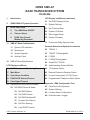
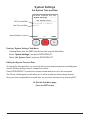
GEMS
Safety Monitoring System
User’s Manual
Model SMS-AT
305 Bend Hill Rd., Fredonia, PA 16124, USA
Ph: 724-962-9231 ● Fax: 724-962-3611
www.graceindustries.com
GEMS SMS-AT
BASE TRANSCEIVER SYSTEM
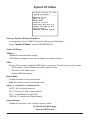
Contents
1.
Introduction
2.
GEMS SMS-AT System Operation
LCD Display and Menus (continued)
30. Set PASS Display Priority
31. System Settings
8.
Quick Start Guide
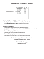
33. Set Time and Date
8.
Turn SMS Base ON/OFF
34. System I/O Status
8.
Clear an Alarm
35. Data Logger Setup
9.
PASS View Screen /
Monitoring Personnel
36. System Firmware
37. Power and Relay Options Cords
11. SMS-AT Base Familiarization
11. System LED Indicators
Personal Alarms and System Accessories
12. Microphone
38. TPASS® 3
13. System Keypads
39. TPASS® 3 Rechargeable
14. Auxiliary Panel
40. LTX200
41. LTX200 Rechargeable
15. SMS-AT Base Specifications
LCD Display and Menus
42. SuperCELL® SC500
43. Understanding System Abilities
16. PASS View Screen / Monitoring Personnel 44. T3 Repeater Option
17. Main Menu
46. Remote Enhanced Receiver Option
18. Clear Alarm Condition
48. Locator Transponder (LT100) Option
19. EVACUATE Selected Passes
49. Programmable Telephone Dialer Option
20. Clear Signal Timeout
21. Add/Remove PASS Device & Name
22. Edit PASS Device & Name
23. Edit PASS Name
24. Pair PASS Device
Appendix - SMS Configuration Tool
A1. Pass Device Configuration
A2. System Settings
A3. Location Name Configuration
A4. Even Recorder / Logger
26. Edit PASS Address/ID
27. Program Pass Device
28. Edit Port Steering
29. Local PASS Timeout
© 2013, Grace Industries, Inc.
GEMS SMS-AT UI 070113
Introduction
The GEMS Safety Monitoring System, consists of two primary components: a Base/Transceiver
and a Transmitting Personal Alert Safety System or TPASS® man-down alarm. Other equipment
such as T3 Repeaters and Remote Enhanced Receivers may also be used to enhance system
effectiveness in challenging environments
NOTE: The Safety Monitoring System will be referred to as SMS-AT or SMS Base, and the
Transmitting Personal Alert Safety or Man-down devices will be referred to as TPASS® or
SuperCELL®. All Grace Transmitting Personal Safety devices may be used with SMS-AT. Compatible telemetry devices include: TPASS® 3, TPASS® 3-R, LTX200, LTX200-R, SC500.
The SMS-AT Base/Transceiver is the heart of the system. The SMS Base receives Emergency
Alarm signals, check-in signals and other status signals from the TPASS® devices continuously.
SMS Base provides electronic accountability for all TPASS® devices in the immediate area and
displays their current status on the LCD Display Screen. This information provides supervisory
personnel with details of who is active, their status and immediate notification of any Emergency
Alarm conditions.
TPASS® is a generic term for the Transmitting Personal Alert Safety System. TPASS® will automatically call for help if the wearer becomes motionless for a predetermined period of time. Preset
times to Alarm are available in 30, 60, 90 and 120 seconds. Personnel may also manually activate
the emergency call for help by pressing the Alarm button at any time.
When a TPASS® Alarm is activated (manually or through lack of motion) the TPASS® will sound a
loud audio alarm and transmit an emergency radio signal to the SMS Base.
When the SMS Base receives an Alarm signal, the red Alarm Status Indicator will flash and the
TPASS® device in Alarm is displayed in the top line of the SMS Base LCD Display. This allows supervisory personnel the opportunity to take appropriate action in a timely manner. When an Alarm is
received, the SMS Base can also be used to activate an Automatic Telephone Dialer.
The SMS-AT provides the supervisor with the ability to EVACUATE or callback personnel from
unsafe or deteriorating conditions. The Evacuation process involves a sending a signal to one
person, a group, or all personnel as needed.
Effective radio signal range is typically one half mile and can be enhanced with optional equipment
such as the T3 Repeater and Remote Enhanced Receiver. No FCC License is required for operation.
1
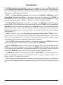
GEMS SMS-AT
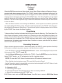
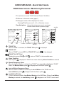
SYSTEM OPERATION
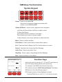
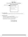
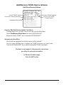
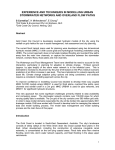
Alarm Signal Repeated
TPASS® Device
Sends Alarm Signal
to T3 Repeater
T3 Repeater
(OPTIONAL)
EVAC Signal Sent
(to repeater)
EVAC Signal Repeated
and Sent to TPASS® Device
EVAC Signal Sent to TPASS®
TPASS® Device
Lone Worker Down
TPASS Device Sends Alarm Signal
to GEMS SMS Base When He Can’t
®
2
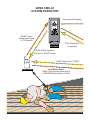
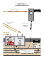
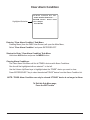
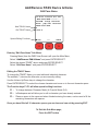
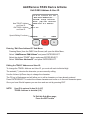
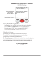
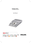
GEMS SMS-AT
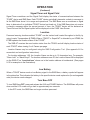
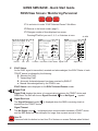
SYSTEM OPERATION
Alarm Signal Repeated
and Sent to Remote Receiver
Remote Enhanced
Radio Receiver
(OPTIONAL)
Alarm Signal Repeated
to SMS Base
ALARM
Remote Receiver
Sends Signal to
SMS Base
LOCAL
RX
POWER
TX
REMOTE
TX
o
o
o
o
o
o
o
o
o
o
o
o
o
o
o
o
o
o
o
o
o
o
o
o
o
o
o
Automatic
Telephone Dialer
(OPTIONAL)
o
o
o
EXIT
o
PLAY/
STOP
o
AUDIO
TONE
o
RECORD
ENTER/
SELECT
o
AUX
MENU
o
VOLUME
o o
o
VOLUME
POWER
o
o
F3
o
o
o
F2
o
o
o
o
o
F1
o
o
o
o
o
MICROPHONE
o
RX
BATTERY
Grace Industries, Inc.
Safety Monitoring System
Fredonia, PA 16124 USA
G.E.M.S. BY GRACE IND., INC.
TP-HP-M-XX12080002
))
Automatic Voice/Pager Dialer
GEMS SMS Base Sends Signal
to Telephone Dialer
3
Safety Monitoring System
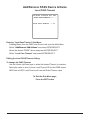
NOTE: Always Test the SMS Base Prior to Each Use. It is important to be thoroughly familiar
with system operation and screen information before attempting field use.
The SMS-AT Base/Transceiver is the heart of the system. The SMS Base receives Emergency
Alarm signals, check-in signals and other status signals from TPASS® devices continuously. The
SMS Base provides electronic accountability for all properly programmed Grace Telemetry devices
in the immediate area and displays their current status on the LCD Display Screen. This information
provides management personnel with the details of who is active, their status and immediate notification of any Emergency Alarm conditions.
When situations become unsafe or deteriorate rapidly, the SMS-AT has the ability to EVACUATE
or callback personnel. The Evacuation process involves a signal being sent to TPASS® from the
SMS Base. When the TPASS® receives the signal, it automatically sends an electronic acknowledgement back to the SMS Base - this lets the supervisor know the Evacuation signal was successfully received by the TPASS®. When the TPASS® receives the Evacuate signal, a loud chirping audio
alarm tone is accompanied by rapidly flashing Amber LEDs. This alerts and notifies personnel that
he is being ordered to evacuate. The TPASS® user manually acknowledges the Evacuation signal
by pressing both side buttons simultaneously - the operational tones will be heard and the flashing
LEDs and loud chirping audio tones will cease. This manual acknowledgement lets the supervisor
know the Evacuation signal was received and understood by the TPASS® user.
Versatility of SMS Base
The SMS Base is designed for desktop use but can be converted for mounting on a wall or other
appropriate non-metallic, vertical surface. By removing the four screws on the triangular desktop
brackets, the SMS Base is released for mounting on a wall or other surface. Appropriate anchors
and stainless steel screws should used be when mounting to any surface or structure. As noted
earlier, the SMS Base should not be mounted on a metallic surface as it may interfere with radio
signal effectiveness.
Positioning of SMS Base
The SMS Base should be positioned approximately 4-5 feet off the ground on a non-metallic surface.
Restrict operation of high-power radio transmitters or other devices within 3’ of the SMS Base.
Power System
The SMS Base incorporates a rechargeable lead acid battery. The system may be used for approximately 16 hours on a full charge, without auxiliary power. A 120 VAC power cord is provided for
extended use or permanent installation. Battery recharging can be accomplished in approximately
16 hours by attaching the 120 VAC power cord to the base. A 12 VDC power adapter is also
provided for use with most vehicle 12 VDC systems. This allows for extended use in the field where
battery life has been exceeded and 120 VAC is not available.
Battery Maintenance
If not used on a regular basis or if stored for an extended period of time, connect the SMS Base to
120 VAC Power for 4 hours every month to ensure battery is fully charged and ready for use.
4
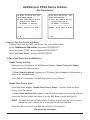
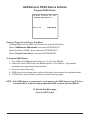
OPERATION
Monitor Personnel
Press the POWER button to turn SMS Base ON. The LCD screen will light up and display the telemetry devices programmed to the base. The SMS Base is ready to monitor personnel.
LCD Display
The number of TPASS® or telemetry devices showing on a single screen is user-selectable and can
be changed to display 2, 4, 6 or 8 devices per screen by pressing the F3 button located under the
LCD Display.
Nine (9) different fields of information are provided for each of the TPASS® or telemetry devices
displayed. The fields are: User Name, Unit ID number, ON/OFF status, Alarm, EVAC Status, Signal
Timer, Signal Indicator, Location information and Low Battery Indicator.
These fields are automatically displayed as the TPASS® communicate with the SMS Base.
The TPASS® Username is matched with a TPASS® User ID and entered into the system memory
through downloading with the SMS Configuration Tool or the keypad data entry process.
TPASS® User Name
This field is used to display names, assignment locations or other means of identifying the personnel
associated with a specific User ID Number. The field consists of 15 character locations.
User ID
Individual TPASS® devices are programmed to a specific User ID number. The User ID number is
used to identify the specific TPASS® and the personnel associated with the corresponding TPASS®
Username or location.
User ID can be viewed by pressing and holding the Aux button.
ALARM
Vol: 54%
The System ID - User ID will be
displayed
the Usernames.
PASS
View over
Page#01
of 02
---------------------------
Release the Aux button when Matts
finishedLOCATOR
viewing User
12 -ID and the screen will return to normal.
JOE DAVIES
15 LOCATOR A
08 Clint A C2-36 06 Drew Es C2-32 06 SHOP 1
08 System ID
User
LOCATOR
2
07 ID
LOU HORTON
10 ===========================
Page#02
TPASSHome
ON / OFF#Disp
TPASS® ON/OFF field displays the current ON or OFF status of TPASS® in the immediate area. An
OFF symbol is displayed in this field until the TPASS® is turned ON. When a TPASS® is activated,
the TPASS® ON/OFF field displays an ON symbol. When a TPASS® is turned OFF, the OFF symbol
will be displayed.
5
OPERATION
(Continued)
ALARM
When the SMS Base receives an Alarm signal, the red Alarm Status Indicator will flash and the prerecorded audio alarm message will play. The TPASS® device in Alarm is displayed at the top of the
Monitoring screen and the Alarm Bell symbol will appear in the User’s status line. The audio alarm
message can be silenced by pressing the PLAY/STOP button. The Alarm Condition can be cleared
easily by holding the AUX button and pressing the Menu button to open the Clear Alarm Condition
submenu - use the Volume Up/Down keys to select the Username in Alarm and press Enter/Select
to clear the Alarm.
When an Alarm Condition is received by the SMS Base, a heart symbol or man-down symbol will
also appear beside the Alarm symbol. The heart symbol appears when the TPASS® User has manually pressed the Emergency Alarm Button. The man-down symbol is displayed when Lack-of-Motion
by the TPASS® User causes the Alarm Condition.
Clear Alarms
To clear an Alarm Condition hold down the AUX key and Press the Menu key. The Clear Alarm Condition Screen will appear. Use the volume Up or Down keys to select and highlight the Alarm to be
cleared. Press the Enter/Select key to clear the Alarm Condition chosen. Please note that the Alarm
Condition may only be cleared if the TPASS® has been reset and no longer sending emergency
transmissions. As needed, select another Alarm Condition to clear or press the Exit key twice to
return to the PASS View Screen.
Evacuating Personnel
When a situation becomes unsafe or deteriorates rapidly, the SMS-AT gives supervisors the ability
to Evacuate or callback one person, a group, or all personnel as needed.
Press the F1 key to open the “EVAC Selected Passes” screen. The list displayed is all personnel
in the area with their TPASS® turned ON.
Use the Volume Up/Down keys to highlight the TPASS®. Press the ENTER key to select the highlighted TPASS® device – an “S” will appear to the left of selected devices.
NOTE: F1 clears the EVAC Status of selected devices; F2 selects all devices at once.
When finished selecting devices, press F3 to send the Evacuation Signal.
As the Evacuation signal is transmitted, received and acknowledged, the EVAC Status of each
TPASS® device is indicated by the following:
S: Selected for EVAC
T: Transmitting EVAC signal
E: Automatic Electronic Acknowledgement has been received by SMS-AT
e: Manual Acknowledgement by the TPASS® user
EVAC Status is also seen on PASS View Screen. Press Exit twice to return to PASS View Screen.
6
OPERATION
(Continued)
Signal Timer and Signal Field
Signal Timer countdown and the Signal Field display the status of communications between the
TPASS® device and SMS Base. Each TPASS® device periodically transmits a check-in message to
let the SMS Base know it is in range and operational. The SMS Base uses a countdown or signal
timer to determine if an individual TPASS® device has timed out. If the SMS Base does not receive
a check-in message within the pre-set amount of time, the TPASS® device will be declared as
Timed-Out and the No-Signal symbol will be displayed on the PASS View Screen.
Location
Personnel wearing location-enabled TPASS® can be tracked and located throughout a facility by
using Locator Transponders (LT100). When a TPASS® or SuperCell® is detected by an LT100, the
LT100 updates the location status of the TPASS®.
The SMS-AT receives the new location status from the TPASS® and will display location status of
each TPASS® when viewing 2 or 4 Passes per page.
Location Names may be configured using the SMS Configuration Tool. (See appendix A3 for
screenshot and configuration instructions).
For location addresses 1-50, the Location Name can be up to 16 characters long. For example:
“Chem Lab1” or “Mach Shop2”. For location addresses over 50, the Location Name will be displayed
on the SMS-AT as “Location# xxx” where xxx is the location address in hexidecimal. (See pages
9-10 for examples in the illustrations).
Low Battery
When a TPASS® device sends a Low-Battery signal to the SMS Base, a battery symbol will appear
in the status line. This indicates the battery in the specific device needs replaced or (for rechargeable
units) the device needs charged.
Turn Base OFF
To turn SMS Base OFF, press and release the AUX and POWER buttons. The SMS Base will power
down and the LCD screen will go dark in approximately two seconds.
In the OFF mode, the SMS Base no longer monitors personnel.
7
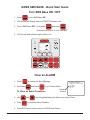
GEMS SMS BASE - Quick Start Guide
Base Activation
Turn SMS Base ON / OFF
POWER
1. Press pwr
to turn SMS Base ON.
2. LCD Screen will display status of TPASS® Devices in use.
AUX
POWER
3. To turn SMS Base OFF: Hold down aux
and press pwr
Release both buttons to turn SMS OFF
4. LCD Screen and Indicator lights will shut off.
ALARM
LOCAL
RX
POWER
TX
10:23:00 11/05/12 Vol: 54%
PASS View Page#01 of 08
---------------------------
JOE DAVIES
-
15
--
REMOTE
RX
BATTERY
TX
===========================
John B
-MICROPHONE
08
--
===========================
EVAC
Home
#Disp
F1
F2
F3
VOLUME
VOLUME
RECORD
AUDIO
TONE
POWER
AUX
MENU
ENTER/
SELECT
PLAY/
STOP
EXIT
))
Clear an ALARM
PLAY/
1. Press p/s
STOP
to silence the Alert Message.
AUX
2. Hold down aux and press
m
MENU
to go to Alarm Menu.
To Clear an Alarm Condition:
3. Use up
VOLUME
and
dn
10:36:00 11/05/12 Vol: 54%
Clear Alarm Condition
--------------------------UP/DOWN select: Enter clear
*Jon Sample
JOE DAVIES
John B
Highlighted
Selection
keys to highlight/select the Alarm you want to Clear.
VOLUME
4. Press ENTER/
e/s to clear the Alarm Condition.
SELECT
5. Press EXIT button twice to return to PASS View Screen.
8
GEMS SMS BASE - Quick Start Guide
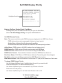
PASS View Screen / Monitoring Personnel
F1
F2
F3
F1 Is a shortcut to enter “EVAC Selected Passes” Sub-Menu.
F2 Returns to the home screen (page 1).
F3 Changes number of lines displayed on screen.
Pressing F3 will let you see 2, 4, 6, or 8 devices at once.
Page Navigation: Volume Up advances screen to next page
Volume Down returns to previous page
10:23:00 11/05/12 Vol: 54%
PASS View Page#01 of 08
---------------------------
ALARM
Vol: 54%
PASS View Page#01 of 04
---------------------------
Jon Sample
Chem Lab1
Jon Sample
15
--
JOE DAVIES
-
John B
08
--
OFF
--
Location#2E2
Matt King
07
-06
--
Location#2E27
-===========================
EVAC
Home
#Disp
===========================
EVAC
Home
#Disp
ON
15
-
Mach Shop2IF7
===========================
JOE DAVIES
Mach Shop2
12
-e
Chem Lab1
Location
TPASS® OFF
When a TPASS® is turned OFF, the TPASS® OFF symbol
TPASS® ON / OFF Field
Displays the current ON
ALARM
Vol: 54%
PASS View Page#01 of 02
--------------------------Jon Sample
12
e
JOE DAVIES
15 John B
08 Matt King
06 Ralph Custer 06 Rob Tonks
08 Kevin Smith
07 LOU HORTON
10 ===========================
EVAC
Home
#Disp
Username Low Battery Signal Timer
Warning
TPASS® ON
When a TPASS® is activated, the TPASS® ON symbol
or OFF
ALARM
Signal Field
is displayed.
will be displayed.
status of TPASS® in the immediate area.
Alarm Condition
Alarm Symbol
is displayed in TPASS® user status when any Alarm Condition is received
Manual Emergency Alarm
When the Alarm Condition is initiated by a TPASS® user manually activating his TPASS®
Alarm, the Manual-Alarm symbol
is displayed with the Alarm symbol
Lack-of-Motion Emergency Alarm
When an Alarm Condition is caused by a Lack-of-Motion of the TPASS user, the
Lack-of-Motion symbol
is displayed with the Alarm symbol
Low Battery Warning
TPASS® devices will send a Low Battery Warning to the SMS Base. When a Low-Battery
Warning is received, the Low-Battery symbol
is displayed in the TPASS® User’s status.
9
GEMS SMS BASE - Quick Start Guide
Base Activation
PASS View Screen / Monitoring Personnel
F1
F2
F3
F1 Is a shortcut to enter “EVAC Selected Passes” Sub-Menu.
F2 Returns to the home screen (page 1).
F3 Changes number of lines displayed on screen.
Pressing F3 will let you see 2, 4, 6, or 8 devices at once.
ALARM
10:23:00 11/05/12 Vol: 54%
PASS View Page#01 of 08
---------------------------
ALARM
Vol: 54%
PASS View Page#01 of 04
---------------------------
Jon S C1-20
Chem Lab1
-
Jon Sample
15
--
JOE DAVIES
===========================
JOE D C1-36
Mach Shop2 - -
08
--
E
ON
OFF
Mach Shop2IF7
--
Matt King
Location
15
-
John B
Location#2E2
===========================
EVAC
Home
#Disp
User ID
12
-e
Chem Lab1
07
-06
--
Location#2E27
-===========================
EVAC
Home
#Disp
ALARM
Vol: 54%
PASS View Page#01 of 02
--------------------------Jon Sample
12
e
JOE DAVIES
15 John B
08 Matt King
06 Ralph Custer 06 Rob Tonks
08 Kevin Smith
07 LOU HORTON
10 ===========================
EVAC
Home
#Disp
Username EVAC Status Signal Timer
Signal Field
EVAC Status:
As the EVAC signal is transmitted, received and acknowledged, the EVAC Status of each
TPASS® device is indicated by the following:
S - Selected for EVAC
T - Transmitting EVAC
E - Automatic Acknowledgement has been received by SMS-AT
e - Manual Acknowledgement by the TPASS® user
EVAC Status is also displayed on the EVAC Selected Passes screen.
Signal Field
Signal Field displays the status of communications between the TPASS® device and
SMS Base. The field will show a Signal Received
or a No-Signal
symbol.
Signal Received
The Signal Received symbol
is displayed when the SMS is receiving check-in
®
signals from the TPASS device.
Signal Timeout
The No-Signal symbol
is displayed when communication between a TPASS® device
and the SMS Base has been disrupted for longer than a preset amount of time.
AUX
User ID
Press and hold Aux button to view User ID of devices on screen. Release when finished.
10
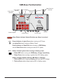
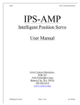
SMS Base Familiarization
Power Status
Indicators
Alarm Status
Indicator
Radio Receiver
Antennas
LCD Display
Signal Activity
Indicators
ALARM
LOCAL
RX
POWER
TX
REMOTE
TX
o
o
o
o
o
o
o
o
o
o
o
o
o
o
o
o
o
o
o
o
o
o
o
o
o
o
o
o
o
o
o
PLAY/
STOP
o
AUDIO
TONE
o
RECORD
ENTER/
SELECT
o
AUX
MENU
o
VOLUME
o o
o
VOLUME
POWER
o
o
F3
o
o
o
F2
o
o
o
o
o
F1
o
o
o
o
o
MICROPHONE
o
RX
BATTERY
Grace Industries, Inc.
Safety Monitoring System
Fredonia, PA 16124 USA
G.E.M.S. BY GRACE IND., INC.
TP-HP-M-XX12080002
EXIT
))
System Keypad
ALARM
POWER
Speaker
Auxiliary Panel
Function Keys
Alarm Status Indicator flashes Red when an Alarm is received.
Power Indicator will glow Green when running on AC Power,
and glows Red when running on Battery Power.
Power Indicator will flash Red when running on LOW Battery,
and will flash Green when running on external 12V power.
BATTERY
Battery Indicator glows when running on battery power.
1. Glows RED when running on LOW Battery. Charge Immediately.
2. Glows Green when running on greater than 20% battery power.
Battery Indicator flashes when the SMS Base is Charging.
1. Flashes RED while charging a Battery with less than 80% charge.
2. Flashes Green when charge reaches 80% of battery power.
11
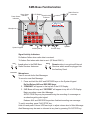
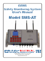
SMS Base Familiarization
Power Status
Indicators
Alarm Status
Indicator
Radio Receiver
Antennas
LCD Display
Signal Activity
Indicators
ALARM
LOCAL
RX
POWER
TX
REMOTE
TX
o
o
o
o
o
o
o
o
o
o
o
o
o
o
o
o
o
o
o
o
o
o
o
o
o
o
o
o
o
o
o
PLAY/
STOP
o
AUDIO
TONE
o
RECORD
ENTER/
SELECT
o
AUX
MENU
o
VOLUME
o o
o
VOLUME
POWER
o
o
F3
o
o
o
F2
o
o
o
o
o
F1
o
o
o
o
o
MICROPHONE
o
RX
BATTERY
Microphone
Grace Industries, Inc.
Safety Monitoring System
Fredonia, PA 16124 USA
G.E.M.S. BY GRACE IND., INC.
TP-HP-M-XX12080002
EXIT
))
System Keypad
Speaker
Auxiliary Panel
Function Keys
Signal Activity Indicators:
Rx flashes Yellow when radio data is received.
Tx flashes Red when radio data is sent. (AT Model ONLY).
LOCAL
RX
TX
MICROPHONE
Local refers to the SMS Base
Radio Receiver Antennas.
REMOTE
RX
TX
Remote refers to an optional External
Receiver which would be plugged into
the Auxiliary Panel.
Microphone:
Used to record Audio Alert Messages.
To record a new Alert Message:
1. Press and hold the AUX and RECORD keys on the System Keypad.
Do Not Relase AUX and RECORD keys.
2. “ERASING” will appear in the top-left of the LCD Display.
3. SMS Base will beep and “RECORD” will appear in top-left of LCD Display.
Begin recording a new Alert Message.
AUDIO TONE key may be pressed during the recording of a message as
an attention getting alert signal.
Release AUX and RECORD keys when finished recording new message.
To verify recording, press PLAY/STOP key.
Hold Aux and press Volume UP/Down keys to adjust volume level of Alert Message.
Alert Message may be reset or silenced at any time by pressing PLAY/STOP key.
12
SMS Base Familiarization
System Keypad
POWER
AUX
MENU
VOLUME
VOLUME
RECORD
AUDIO
TONE
PLAY/
STOP
ENTER/
SELECT
EXIT
))
Power: Press to turn power ON.
Hold down Aux and press Power and release both
buttons to turn SMS Base OFF.
Volume UP/Down: Volume control, page and menu navigation.
Hold Aux and Press Volume Up/Down to adjust volume.
In Pass View Screen:
Press Volume Down to advance to next page.
Press Volume Up to return to previous page.
In Menu Screens, use Volume Up/Down to make selections.
Menu: Press to access the Menu.
Enter/Select: Press to enter data and select Menu options.
Aux: Press and hold to display User ID of devices shown on screen.
Record: Used with Aux to record an Alert Message.
Audio Tone: Press to play Audio Tone.
Play/Stop: Press to play or stop playing the Alert Message.
Exit: Press to exit Menu or Sub-Menu.
Function Keys
10:23:00 11/05/12 Vol: 54%
PASS View Page#01 of 08
---------------------------
Jon Sample
-
15
--
===========================
JOE DAVIES
--
08
--
===========================
EVAC
Home
#Disp
F1
F2
F3
Actions for each Function key (F1, F2, and F3) are shown on
the LCD Display, directly above each function key.
For example: in the PASS View Screen shown here
F1 is shortcut to enter “EVAC Selected Passes” Sub-Menu.
F2 Returns to the Home Screen (page 1).
F3 Changes number of lines displayed on screen.
Pressing F3 will let you see 2, 4, 6, or 8 devices at once.
13
SMS Base Familiarization
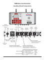
Auxiliary Panel Components
ALARM
LOCAL
RX
POWER
TX
REMOTE
TX
o
o
o
o
o
o
o
o
o
o
o
o
o
o
o
o
o
o
o
o
o
o
o
o
o
o
o
o
o
o
o
PLAY/
STOP
o
AUDIO
TONE
o
RECORD
ENTER/
SELECT
o
AUX
MENU
o
VOLUME
o o
o
VOLUME
POWER
o
o
F3
o
o
o
F2
o
o
o
o
o
F1
o
o
o
o
o
MICROPHONE
o
RX
BATTERY
Grace Industries, Inc.
Safety Monitoring System
Fredonia, PA 16124 USA
G.E.M.S. BY GRACE IND., INC.
TP-HP-M-XX12080002
EXIT
))
10 Watt
External Audio
Output
Mini
USB
Auxiliary Panel
120 VAC
12 VDC
Relay
Contact
Remote
Receiver
Open
Collector
1-8
Open
Collector
9-16
FUSE
Power Cord
Retainer Fuse Holder
1 Amp Fuse
5 Pin Connector
Remote Enhanced Radio
Receiver connector
Line-Level
Output
Auxiliary 2 Pin Receptacle
Auxiliary 12 volt DC power supply
Auxiliary 5 Pin Receptacle
Auxiliary contacts for activation of
Telephone Dialers or external devices.
Auxiliary Receptacle Pin Assingments
Pin 1: Relay Normally Open ..... Green
Max 12V 5Amp Pin 2: Relay Common ............... White
Pin 3: Relay Normally Closed ... Orange
12V 1Amp Fused Pin 4: +12 volts DC Output ....... Red
Pin 5: Ground ........................... Black
{
{
14
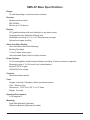
SMS-AT Base Specifications
Range:
1/2 mile depending on environmental conditions.
Receiver:
Spread spectrum serial
902-928 Mhz
Monitor up to 72 devices
Display:
LCD graphics display with auto backlight on any button press
Programmable auto backlight off/sleep time
Selectable monitoring of 2, 4, 6, or 8 Pass devices per page
Optional auto page-scrolling.
Alarm Condition Display:
User recordable Audio Alert Message
Strobing Red lights
1 Form-C alarm relay output
User selectable Open Collector output closures
Power Options:
12 Volt rechargeable sealed lead-acid battery providing 16 hours continuous operation.
Recharging time of 12-16 hours for the internal battery.
External 12VDC supply
120/240VAC line voltage
Controls:
Sealed membrane switch
Case:
Rugged, Industrial, Fiberglass, Water-resistant enclosure
Color: Medium Gray
Dimensions: 10.25” W x 6.25” H x 3.5” Deep
Weight: 9 pounds
Operation Environment:
0-140 degrees F
Mounting:
Desk/Table Brackets (Standard)
Wallmount Brackets (Optional, provided)
15
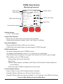
PASS View Screen
Monitoring Personnel
System Status
Page Status
ALARM
Vol: 54%
PASS View Page#01 of 04
---------------------------
Jon Sample
23
--
Chem Lab1
JOE DAVIES
PASS Status Window
Mach Shop2IF7
20
Peter D
Jeff
®
--
Function Button Options
Speaker Volume
TPASS® User Status
19
-22
--
Signal Timer
Location# IF7
-===========================
EVAC
Home
#Disp
F1
F2
F3
Speaker Volume:
0 - Off, 1-100% Volume
System Status Window:
Shows the active status and current system Time and Date.
Possible active statuses to display: Alarm, Play, Record, Low Battery
Page Status Window:
Shows what System Page or Menu you are viewing.
In PASS View, this window shows how many pages of TPASS® data exist.
PASS Status Window:
This section displays the status of TPASS® devices.
The display can be adjusted to show 2, 4, 6, or 8 devices on a single page.
Press Volume Down to advance to next page. Press Volume Up to return to previous page.
When display is set for 2 PASS per page:
Status window will show the Username,
Signal Timer
Character status display: Low Battery, EVAC Status, On/Off, Alarm Condition (Manual or
Lack-of-Motion).
And location data, if PASS is equipped with Locator option.
Function Button Options:
Press F1 Button to enter “EVAC Selected Passes” Sub-Menu
Pressing F2 Button will take you to the Home Screen (Page 1)
Pressing F3 Button will let you choose to display 2, 4, 6 or 8 devices on the PASS View Screen.
Press the Menu Button to open the Main Menu
16
Main Menu
Press the Menu Button to open the Main Menu
Highlighted Selection
10:25:00 11/05/12 Vol: 54%
*Clear Alarm Condition
EVAC Selected Passes
Clear Signal Timeout
Add/Remove PA# & Name
Set Pass Display Priority
System Settings
System I/O Status
Data Logger Setup
System Firmware Report
Entering Main Menu:
Pressing Menu (from the PASS View Screen) will open the Main Menu shown above.
Navigating the Menu:
The Main Menu is a list of available Sub-Menus
One line will be highlighted in bold and starred with an asterisk *
Use the Volume Up/Down keys to select a Sub-Menu
Press Enter/Select to open the selected Sub-Menu
To Exit this Menu page,
Press the EXIT button
17
Clear Alarm Condition
Highlighted Selection
10:26:00 11/05/12 Vol: 54%
Clear Alarm Condition
--------------------------UP/DOWN select: Enter clear
*Jon Sample
JOE DAVIES
Entering “Clear Alarm Condition” Sub-Menu:
Pressing Menu (from the PASS View Screen) will open the Main Menu,
Select “Clear Alarm Condition” and press ENTER/SELECT.
Shortcut to Enter “Clear Alarm Condition” Sub-Menu:
Hold down AUX button and press the MENU button.
Clearing Alarm Conditions:
The Clear Alarm Sub-Menu will list all TPASS® devices with Alarm Conditions.
One line will be highlighted with an asterisk * to the left.
Use the Volume Up/Down keys to highlight/select the TPASS® device you want to clear.
Press ENTER/SELECT key to clear the selected TPASS® device from the Alarm Condition list.
NOTE: TPASS Alarm Condition can only be cleared if TPASS® device is no longer in Alarm
To Exit this Sub-Menu page,
Press the EXIT button
18
EVACUATING Selected Passes
Selected for EVAC
Highlighted Selection
10:26:00 11/05/12 Vol: 54%
EVAC Selected Passes
--------------------------UP/DOWN select: Enter clear
SJon Sample
JOE DAVIES
*Peter D
Cancel
F1
Sel ALL
F2
EVAC
F3
Entering “EVAC Selected Passes” Sub-Menu:
Pressing Menu (from the PASS View Screen) will open the Main Menu,
Select “EVAC Selected Passes” and press ENTER/SELECT.
Evacuating Selected Passes:
The EVAC Selected Passes Sub-Menu will list all ON TPASS® devices.
One line will be highlighted with an asterisk * to the left.
Use the Volume Up/Down keys to highlight the TPASS® device you want to EVAC.
Press ENTER/SELECT key to select the highlighted TPASS® device. - an “S” will appear to left
of selected devices.
F1 (Cancel) clears Evac status of selected device
F2 (Sel All) selects all devices for EVAC - an “S” will appear to left of all devices.
F3 (EVAC) - When finished selecting devices - Press F3 (EVAC) to send the EVAC Signal.
EVAC Status:
As the EVAC signal is transmitted, received and acknowledged, the EVAC Status of each
TPASS® device is indicated by the following.
S - Selected for EVAC
T - Transmitting EVAC
E - Automatic Acknowledgement has been received by SMS-AT
e - Manual Acknowledgement by the TPASS® user
EVAC Status is shown on the EVAC Selected Passes screen and on the PASS View Screen.
NOTE: TPASS® device can only be EVACUATED if TPASS® is ON
To Exit this Sub-Menu page,
Press the EXIT button
19
Clear Signal Timeout
Highlighted Selection
10:26:00 11/05/12 Vol: 54%
Clear Signal Timeout
--------------------------UP/DOWN select: Enter clear
*Peter D
Ralph Custer
Entering “Clear Signal Timeout” Sub-Menu:
Pressing Menu (from the PASS View Screen) will open the Main Menu,
Select “Clear Signal Timeout” and press ENTER/SELECT.
Clearing Signal Timeouts:
This sub-menu will list all TPASS® devices with Signal Timeout Conditions.
One line will be highlighted with an asterisk * to the left.
Use the Volume Up/Down keys to highlight/select the TPASS® device you want to clear.
Press ENTER/SELECT key to clear the selected TPASS® device from the Signal Timeout list.
To Exit this Sub-Menu page,
Press the EXIT button
20
Add/Remove PASS Device & Name
Highlighted Selection
10:28:00 11/05/12 Vol: 54%
Add/Remove PA# & Name
--------------------------Jon Sample
C1 020
JOE DAVIES
C1 036
*Peter D
C1 044
Matt King
C1 004
LOU HORTON
C1 002
Kevin Smith
C1 005
Rob Tonks
C1 016
Ralph Custer
C1 007
Next
Home
Prev
Entering “Add/Remove PASS Device & Name” Sub-Menu:
Pressing Menu (from the PASS View Screen) will open the Main Menu,
Select “Add/Remove PA# & Name” and press ENTER/SELECT.
Navigating the Sub-Menu:
One line will be highlighted in bold and starred with an asterisk *
Use the Volume Up/Down keys to highlight/select the TPASS® device you want to edit.
Only 8 devices can be displayed on each screen.
Press the F1 key to go to the next page.
Pressing F2 will return you to the first page of devices.
Press the F3 key to go to previous page.
Press the ENTER/SELECT key to Edit the selected TPASS® device.
(Continue to next page of this manual for instructions
on Editing the selected TPASS® device)
To Exit this Sub-Menu page,
Press the EXIT button
21
Add/Remove PASS Device & Name
Edit Pass Device & Name
Current TPASS® Name
Current Port Steering Definition
Highlighted Selection
10:29:00 11/05/12 Vol: 54%
Add/Remove PA# & Name
--------------------------TPASS User Name -- Address
Peter D
C1 044
0010 0000 0100 0100 L-OFF
*Edit Pass Name -----Pair Pass Device
Edit Pass Address/IDProgram Pass Device Edit Port Steering -Local Pass Timeout --
Current TPASS® Address
Current Local TPASS®
Timeout Setting
Entering “Edit Pass Device & Name” Sub-Menu:
Pressing Menu (from the PASS View Screen) will open the Main Menu,
Select “Add/Remove PA# & Name” and press ENTER/SELECT.
Select the desired TPASS® device and press ENTER/SELECT.
Navigating the Sub-Menu:
One line will be highlighted in bold and starred with an asterisk *
Use the Volume Up/Down keys to highlight the TPASS® Information you want to edit.
Press the ENTER/SELECT key to edit the highlighted TPASS® Information.
(Continue to next pages of this manual for instructions
on editing the selected information)
To Exit this Sub-Menu page,
Press the EXIT button
22
Add/Remove PASS Device & Name
Edit Pass Name
New TPASS® Name
Old TPASS® Name
Special Editing Functions
10:30:00 11/05/12 Vol: 54%
Edit Pass Name -------------------------------UP/DOWN: change character
Enter: jump next character
TPASS User Name
P
*eter D
A/#
<--
SPACE
F1
F2
F3
Entering “Edit Pass Name” Sub-Menu:
Pressing Menu (from the PASS View Screen) will open the Main Menu,
Select “Add/Remove PA# & Name” and press ENTER/SELECT.
Select the desired TPASS® device and press ENTER/SELECT.
Select “Edit Pass Name” and press ENTER/SELECT.
Editing the TPASS® Name:
To change the TPASS® Name, you must edit each individual character.
The asterisk (*) denotes the character you are currently editing.
Use the Volume Up/Down keys to change the character.
Press ENTER/SELECT to select the chosen character and move on to the next character space.
The Function keys F1-F3 will allow special editing functions.
F1 -- To change between Character Mode (A-Z) and # Mode (0-9).
F2 -- Is Backspace and will allow you to edit a character you have already entered.
F3 -- Places a space in the name and when finished entering the name, can be used to fill the
remaining characters with spaces.
Once you have filled all 16 character spaces you are done and can exit by pressing EXIT.
To Exit this Sub-Menu page,
Press the EXIT button
23
Add/Remove PASS Device & Name
Pair Pass Device
10:29:00 11/05/12 Vol: 54%
Pair Pass Device
--------------------------To Pair Pass Device Follow
Instructions below:
UP ARROW --> Restart
--------------------------Step#1: Testing for Ready
1 05
10:29:06 11/05/12 Vol: 54%
Pair Pass Device
--------------------------To Pair Pass Device Follow
Instructions below:
UP ARROW --> Restart
--------------------------Step#2: Place Pass in Alarm
-- --
2 06
-- --
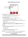
Entering “Pair Pass Device” Sub-Menu:
Pressing Menu (from the PASS View Screen) will open the Main Menu,
Select “Add/Remove PA# & Name” and press ENTER/SELECT.
Select the desired TPASS® device and press ENTER/SELECT.
Select “Pair Pass Device” and press ENTER/SELECT.
To Pair a Pass Device with the SMS Base:
Step#1: Testing for Ready
Before pairing a Pass device, the SMS Base will display “Step#1: Testing for Ready”
while it checks the area for Alarms.
If “Error: Detecting Alarms” appears on LCD Display, find and clear any Pass devices in
Alarm in the immediate area.
When Step #1 is successful, the SMS Base will move on to Step #2
Step#2: Place Pass in Alarm
When SMS Base displays “Step#2: Place Pass in Alarm” - manually press the Alarm
Button on the Pass device.
If “Error: Alarm Not Detected” appears, clear Alarm by simultaneously pressing both side
buttons on the Pass device, then press Up on the SMS Base to restart with Step #1.
NOTE: The SMS Base will indicate an Alarm Condition and this error will occur if you are
attempting to pair a device that is already paired with the SMS Base
When Step #2 is successful, the SMS Base will move on to Step #3
(Continued on next page)
24
Add/Remove PASS Device & Name
Pair Pass Device
10:29:15 11/05/12 Vol: 54%
Pair Pass Device
--------------------------To Pair Pass Device Follow
Instructions below:
UP ARROW --> Restart
--------------------------Step#3: Clear Alarm
3 09
10:29:22 11/05/12 Vol: 54%
Pair Pass Device
--------------------------To Pair Pass Device Follow
Instructions below:
UP ARROW --> Restart
--------------------------Pairing Complete
C1 44
4 07
-- --
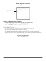
Pair Pass Device (continued):
Step#3: Clear Alarm
When SMS Base displays “Step#3: Clear Alarm”, simultaneously press both side buttons of
the Pass device to clear the Alarm.
If “Error: Alarm Still Detected” appears, make sure there are no other Pass devices in Alarm
in the immediate area. Clear any Alarms and press Up on the SMS Base to restart at Step #1.
Pairing Complete
When Step #3 is successful, the SMS Base will display “Pairing Complete”.
The Pass device is now paired with the SMS Base.
To Exit this Sub-Menu page,
Press the EXIT button
25
Add/Remove PASS Device & Name
Edit PASS Address & User ID
New TPASS® Address
and User ID
Old TPASS® Address
and User ID
Special Editing Functions
10:31:00 11/05/12 Vol: 54%
Edit Pass Address/ID--------------------------UP/DOWN: change character
Enter: jump next character
TPASS User ID & Address
2
*5 005
XXXXX
F1
<--
XXXXX
F2
F3
Entering “Edit Pass Address/ID” Sub-Menu:
Pressing Menu (from the PASS View Screen) will open the Main Menu,
Select “Add/Remove PA# & Name” and press ENTER/SELECT.
Select the desired TPASS® device and press ENTER/SELECT.
Select “Edit Pass Address/ID” and press ENTER/SELECT.
Editing the TPASS® Address and User ID:
To change the TPASS® Address and User ID, you must edit each individual digit.
The asterisk (*) denotes the character you are currently editing.
Use the Volume Up/Down keys to change the character.
The F2 key is Backspace and will allow you to edit a character you have already entered.
Press ENTER/SELECT to select the chosen character and move on to the next character space.
Once you have filled all spaces you are done and can exit by pressing EXIT.
NOTE:
User ID is entered in hex (0-9, A-F)
TPASS® Address is decimal (0-9)
To Exit this Sub-Menu page,
Press the EXIT button
26
Add/Remove PASS Device & Name
Program PASS Device
10:32:00 11/05/12 Vol: 54%
Program Pass Device ---------------------------
PID 25 05.
DOWN ARROW
Entering “Program Pass Device” Sub-Menu:
Pressing Menu (from the PASS View Screen) will open the Main Menu,
Select “Add/Remove PA# & Name” and press ENTER/SELECT.
Select the desired TPASS® device and press ENTER/SELECT.
Select “Program Pass Device” and press ENTER/SELECT.
To Program PASS Device:
1. Turn PASS device ON and place within one (1) foot of the SMS-AT.
2. Ensure NO other PASS devices are ON and within 6’ of the SMS-AT - this prevents
inadvertent reprogramming of those devices.
3. Press the Volume Down key.
4. PASS device should beep within a second, denoting it has received the updated address.
5. If PASS device does not beep - press the Volume Down key again.
NOTE: After PASS device is programmed - cycle power to the PASS device (turn OFF, then
turn back ON) to verify the newly progammed PASS connects with the SMS-AT.
To Exit this Sub-Menu page,
Press the EXIT button
27
Add/Remove PASS Device & Name
Edit Port Steering
10:33:00 11/05/12 Vol: 54%
Edit Port Steering ----------------------------
Existing Port Steering
Byte Definition
New Port Steering
Special Editing Functions
Open Collect Port Steering
*010 0000 0100 0100
0
XXXXX
F1
<--
XXXXX
F2
F3
Entering “Edit Port Steering” Sub-Menu:
Pressing Menu (from the PASS View Screen) will open the Main Menu,
Select “Add/Remove PA# & Name” and press ENTER/SELECT.
Select the desired TPASS® device and press ENTER/SELECT.
Select “Edit Port Steering” and press ENTER/SELECT.
Editing the Port Steering:
To change the port steering, you must edit each of the 16 bits.
The asterisk (*) denotes the character you are currently editing.
Use the Volume Up/Down keys to change the bit.
The F2 key is Backspace and will allow you to edit a bit you have already entered.
Press ENTER/SELECT to select the chosen bit and move on to the next bit.
Once you have filled all 16 bits, you are done and can exit by pressing EXIT.
To Exit this Sub-Menu page,
Press the EXIT button
28
Add/Remove PASS Device & Name
Local PASS Timeout
10:34:00 11/05/12 Vol: 54%
Local Pass Timeout ----------------------------
Local Pass Timeout --- 11
Entering “Local Pass Timeout” Sub-Menu:
Pressing Menu (from the PASS View Screen) will open the Main Menu,
Select “Add/Remove PA# & Name” and press ENTER/SELECT.
Select the desired TPASS® device and press ENTER/SELECT.
Select “Local Pass Timeout” and press ENTER/SELECT.
Editing the Local PASS Timeout Setting:
To change the PASS Timeout:
Use the Volume Up/Down keys to select the desired Timeout (in minutes).
Setting the value to zero (0) turns Local Timeout Off for this PASS device.
PASS with a 0/OFF Local Timeout will use the Global Timeout value.
To Exit this Sub-Menu page,
Press the EXIT button
29
Set PASS Display Priority
Highlighted Selection
10:37:00 11/05/12 Vol: 54%
Set Pass Display Priority
--------------------------Alarm Active (LOCKED)
Pass Device On
*Pass Device Off
Pass Evac Status
Pass Device Timeout
Not Active (LOCKED)
Hide Unset devices -- ON
Entering “Set Pass Display Priority” Sub-Menu:
Pressing Menu (from the PASS View Screen) will open the Main Menu,
Select “Set Pass Display Priority” and press ENTER/SELECT.
Set PASS Display Priority:
Note: This menu controls the order PASS devices are displayed in the PASS View Screen.
PASS device status can be rearranged to highest or lowest priority.
Active Alarm is locked into the top priority position.
Not Active and Hide Unset Devices are locked into the lowest priority positions.
Active Alarm: PASS devices in ALARM (is always the top display priority).
PASS Device On: PASS devices ON and communicating with SMS Base
PASS Device Off: PASS devices OFF and communicating with SMS Base
PASS Device Timeout: Communication between device and SMS Base has timed out
Pass Evac Status: EVAC Status of PASS device (Selected, Transmitting and Acknowledged).
Not Active: Username and ID is programmed into SMS Base but not active.
Hide Unset Devices: Hide PASS devices in list that have a * (star) as first character of their name
To change PASS Display Priority:
Use the Volume Up/Down keys to highlight/select the priority you want to edit.
Press ENTER/SELECT to edit the selected priority
Use Volume Up/Down keys to move selection Up or Down on the list.
Press exit to set new priority
Use Volume Up/Down keys to set Hide Unset Devices to On or Off.
To Exit this Sub-Menu page,
Press the EXIT button
30
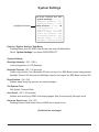
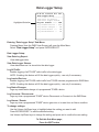
System Settings
Highlighted Selection
10:37:00 11/05/12 Vol: 54%
System Settings
--------------------------Backlight Intensity - 05%
Backlight Timeout --- OFF
*Beep Enabled -------- ON
Set System Clock ---Auto Scroll -------- OFF
Alarm on Signal Loss- OFF
Global Pass Timeout - 08m
Low Battery Timeout - 05m
#Passes display ----- 04x
USB Mode - DataLog Stream
Entering “System Settings” Sub-Menu:
Pressing Menu (from the PASS View Screen) will open the Main Menu,
Select “System Settings” and press ENTER/SELECT.
System Settings:
Backlight Intensity: (Off - 100%)
Controls brightness of LCD Backlight.
Backlight Timeout: (Off, 1-30 seconds)
Power saving feature. Turns Backlight Off after set time of no SMS Base buttons being pressed.
Backlight Timeout Off will mean the Backlight stays On as long as the SMS Base is turned ON.
Beep Enabled: (On / Off)
Enables beep during key presses and status changes.
Set System Clock:
Edit System Time and Date.
Auto Scroll: (Off, 1-20 seconds)
Enables auto-scrolling of PASS View display pages. Sets how frequently the pages scroll.
Alarm on Signal Loss: (On / Off)
Enabling causes Global Alarm when a PASS device signal is lost.
(Continued on next page)
31
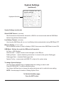
System Settings
(continued)
Highlighted Selection
10:37:00 11/05/12 Vol: 54%
System Settings
--------------------------Backlight Intensity - 05%
Backlight Timeout --- OFF
*Beep Enabled -------- ON
Set System Clock ---Auto Scroll -------- OFF
Alarm on Signal Loss- OFF
Global Pass Timeout - 08m
Low Battery Timeout - 05m
#Passes display ----- 04x
USB Mode - DataLog Stream
System Settings (continued):
Global PASS Timeout: (minutes)
Sets the maximum time/minutes allowed for a PASS to not communicate with the SMS Base
before being declared disconnected.
Low Battery Timeout: (minutes)
How long the SMS Base will run on a Low Battery before automatically turning SMS Base OFF
#Passes display: (2, 4, 6, or 8)
Sets the default number of units to display in PASS View screen when SMS Base is turned ON
USB Mode: Defines the mode the USB port will operate in
No Data -- USB Disabled
Receiver Data -- outputs receiver serial messages to the USB port
DataLog Stream -- outputs data being received as it is stored on the system DataLogger
DataLogger Data -- download DataLogger data
System Config -- communicate with SMS PC config tool for system setup
To change System Settings:
Use the Volume Up/Down keys to highlight/select the setting you want to edit.
Press ENTER/SELECT to edit the selected setting.
Use Volume Up/Down keys to change the setting and press exit to confirm the new setting.
NOTE: See next page for details on Setting System Clock.
To Exit this Sub-Menu page,
Press the EXIT button
32
System Settings
Set System Time and Date
10:23:00 11/05/12 Vol: 54%
System Settings
---------------------------
Old Time and Date
New Time and Date
Special Editing Functions
Set System Clock
---------------------------
10:26:20 11/05/12
10:29
XXXXX
F1
<--
XXXXX
F2
F3
Entering “System Settings” Sub-Menu:
Pressing Menu (from the PASS View Screen) will open the Main Menu,
Select “System Settings” and press ENTER/SELECT.
Select “Set System Clock” and press ENTER/SELECT.
Editing the System Time and Date:
To change the time and date, you must edit the hour/minutes/seconds and month/day/year.
Use the Volume Up/Down keys to change the number.
Press ENTER/SELECT to select the chosen number and move on to the next space.
The F2 key is Backspace and will allow you to edit a number you have already entered.
Once you have completed the time and date, you are done and can exit by pressing EXIT.
To Exit this Sub-Menu page,
Press the EXIT button
33
System I/O Status
10:40:00 11/05/12 Vol: 54%
System I/O Status
--------------------------VBattery:13.35V
VBus: 15.68V
Button Mask:
11111111 11111100
Inputs:Ext PS-1:Ext 12-0
Charger:OC-1:PWR On-12-0
Open Collector
00000000 00000000 0000 00
Entering “System I/O Status” Sub-Menu:
Pressing Menu (from the PASS View Screen) will open the Main Menu,
Select “System I/O Status” and press ENTER/SELECT.
System I/O Status:
VBattery:
Displays the internal battery voltage
If SMS Base is plugged in, this line will display the charging voltage.
VBus:
Display of Bus (control voltage) the SMS Base is running on. This will be from 1 of 3 sources:
AC line power -- Bus will display the power supply’s output
External 12 VDC batter power
Internal SMS Base battery
Button Mask:
Displays the state of front panel buttons
Note: the last two positions will always be 00
Inputs: 1 = detected, 0 = disconnected
Ext PS: AC Line power detected
Ext 12: External 12 VDC supply detected
OC-1: Internal Battery Charge 90%+
PWR On-12: operating on internal battery
Open Collector:
Displays the bit status of the 16 open collector outputs.
To Exit this Sub-Menu page,
Press the EXIT button
34
Data Logger Setup
Highlighted Selection
10:41:00 11/05/12 Vol: 54%
Data Logger Setup
--------------------------View Data Log Report
View Data Logger Stream
*Log All Traffic ---- OFF
Log Loaded Devices - OFF
Log status changes ON
Log Connects/Dis --ON
Log Alarms/Resets -ON
Entering “Data Logger Setup” Sub-Menu:
Pressing Menu (from the PASS View Screen) will open the Main Menu,
Select “Data Logger Setup” and press ENTER/SELECT.
Data Logger Setup:
View Data Log Report:
View datalogger data
View Data Logger Stream:
View data stream as it is stored into the data logger
Log All Traffic:
Enables logging of all TPASS® radio traffic to the data logger.
NOTE: Enabling this feature will fill the data logger quickly - use only if neccessary.
Log Loaded Devices:
Enables logging of all TPASS® radio traffic from TPASS® devices programmed to SMS Base.
NOTE: Enabling this feature will fill the data logger quickly - use only if neccessary.
Log Status Changes:
Logs any status/state-change of a programmed TPASS® device.
Log Connects / Disconnects:
Logs any time a programmed TPASS® device Disconnects or Connects to the SMS Base.
Log Alarms / Resets:
Logs any time a programmed TPASS® device goes into or is reset from an Alarm condition.
To change settings:
Use the Volume Up/Down keys to highlight/select the setting you want to edit.
Press ENTER/SELECT to edit the selected setting.
Use Volume Up/Down keys to change the setting and press exit to confirm the new setting.
To Exit this Sub-Menu page,
Press the EXIT button
35
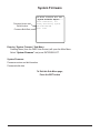
System Firmware
Firmware Version and
Build Number
Firmware Build Date
10:43:00 11/05/12 Vol: 54%
System Firmware Report
--------------------------Grace Industries, Inc.
Safety Monitoring System
vX.X Build# XXX
Date Time
Entering “System Firmware” Sub-Menu:
Pressing Menu (from the PASS View Screen) will open the Main Menu,
Select “System Firmware” and press ENTER/SELECT.
System Firmware:
Firmware version and build number
Firmware build date
To Exit this Sub-Menu page,
Press the EXIT button
36
Auxiliary Components
Power Cords and Relay Options Cord
120-240 Volt AC Power Cord
Approximately 6’ Long
Plug into power receptacle on bottom
of SMS Base to supply auxiliary power
and charge internal battery.
Plug into 120-240 VAC outlet for power.
Also used for charging internal battery.
12 Volt DC Adapter Cord
Approximately 46” Long
Plug into 12VDC vehicle power adapter/outlet
2 Pin connector plugs into
2-Pin Auxiliary Power Receptacle
on bottom of SMS Base
Relay Options Cord
Approximately 10’ Long
5 Pin connector plugs into
5-Pin Auxiliary Power Receptacle
on bottom of SMS Base
Auxiliary 5 Pin Receptacle Outputs
Pin 1: Relay Normally Open ..... Green
Max 12V 5Amp Pin 2: Relay Common ............... White
Pin 3: Relay Normally Closed ... Orange
12V 1Amp Fused Pin 4: +12 volts DC Output ....... Red
Pin 5: Ground ........................... Black
{
{
37
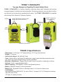
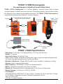
TPASS® 3 EVACUATE
Two-way Emergency Signaling Personal Safety Alarm
TPASS® 3 EVACUATE is a two-way signaling, man-down alarm which transmits and receives
encrypted signals for reliable and secure operation. Protection provided by intrinsic safety certification allows for use in almost any hazardous environment. The TPASS® 3 EVACUATE is compatible
with existing Grace Industries’ Telemetry Systems.
Antenna
TPASS® 3 Shown with
Accountability Key
in Place
Unique LED Patterns Illuminate Case
During ON, Pre-Alert and Alarm
D-Ring and
Grip Clip
Alarm
Button
Reset
Buttons
Resonating Sound Ports
TPASS® 3 Specifications
•
•
•
•
•
•
•
•
•
•
Dimensions: 2-1/8” wide, 2-1/4” deep (with clip), 4-1/8” high (with antenna).
Weight: 7.9 ounces.
Alarm Audio Output: 98+ dBA @ 10 feet.
Case: Apache Yellow, translucent polycarbonate, rugged, impact and high temperature resistant. Entire case glows during Sensing, Pre-Alert and Alarm.
Methods of Attachment: Rugged Grip Clip and D-ring for versatility in attaching to clothing.
Antenna: Small, rugged and replaceable.
Radio Frequency: 902-928MHz, License Free Spread Spectrum.
Battery: MN1604 Duracell 9 volt recommended.
Battery Life: Estimated 40 hours in Sensing mode or 4 to 6 hours in Alarm mode.
Certifications:
Intrinsically Safe per ANSI/UL913. For use in Class 1, Groups A, B, C & D Hazardous locations.
CSA C22.2 No.157-92.
FCC part 15, Industry Canada.
38
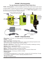
TPASS® 3 Rechargeable
Two-way Emergency Signaling Personal Safety Alarm
TPASS® 3 Rechargeable is a two-way signaling, man-down alarm which transmits and receives
encrypted signals for reliable and secure operation. Protection provided by intrinsic safety certification allows for use in almost any hazardous environment. The TPASS® 3 Rechargeable is compatible with existing Grace Industries’ Telemetry Systems.
Antenna
Unique LED Patterns Illuminate Case
During ON, Pre-Alert and Alarm
D-Ring and
Grip Clip
Alarm
Button
Reset
Buttons
TPASS® 3
Rechargeable
Shown with
Key-Charger
in Place
Charging
Contacts
Resonating Sound Ports
120VAC Charger
Adapter (Optional)
12 VDC Charger Adapter
(Standard)
TPASS® 3 Specifications
•
•
•
•
•
•
•
•
•
•
•
Dimensions: 2-1/8” wide, 2-1/4” deep (with clip), 4-1/8” high (with antenna).
Weight: 7.5 ounces.
Alarm Audio Output: 92 dBA @ 10 feet.
Case: Apache Yellow, translucent polycarbonate, rugged, impact and high temperature resistant. Entire case glows during Sensing, Pre-Alert and Alarm.
Methods of Attachment: Rugged Grip Clip and D-ring for versatility in attaching to clothing.
Antenna: Small, rugged and replaceable.
Radio Frequency: 902-928MHz, License Free Spread Spectrum.
Battery: Integrated, intrinsically safe Lithium-ion battery.
Battery Life: Estimated 80 hours in Sensing mode or 4 to 6 hours in Alarm mode.
Battery Charging: 6 to 8 hours at 12VDC or 120 VAC
Certifications:
Intrinsically Safe per ANSI/UL913. For use in Class 1, Groups A, B, C & D; and Class II, Groups
E, F, G: Division 1 Hazardous locations. Operating Temperature Code T6.
CSA C22.2 No.157-92.
FCC part 15, Industry Canada.
39
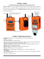
TPASS® LTX200
One-Way Emergency Signaling Personal Safety Alarm
TPASS® LTX200 is a one-way signaling, man-down alarm which transmits encrypted signals for
reliable and secure operation. Protection provided by intrinsic safety certification allows for use in
almost any hazardous environment. The TPASS® LTX200 is compatible with existing Grace Industries’ Telemetry Systems.
Antenna
TPASS® LTX200
Shown with
Accountability Key
in Place
Unique LED Patterns Illuminate Case
During ON, Pre-Alert and Alarm
D-Ring and
Grip Clip
Alarm
Button
Reset
Buttons
Resonating Sound Ports
TPASS® LTX200 Specifications
•
•
•
•
•
•
•
•
•
•
Dimensions: 2-1/8” wide, 2-1/4” deep (with clip), 4-1/8” high (with antenna).
Weight: 7.9 ounces.
Alarm Audio Output: 98+ dBA @ 10 feet.
Case: Apache Orange, translucent polycarbonate, rugged, impact and high temperature resistant. Entire case glows during Sensing, Pre-Alert and Alarm.
Methods of Attachment: Rugged Grip Clip and D-ring for versatility in attaching to clothing.
Antenna: Small, rugged and replaceable.
Radio Frequency: 902-928MHz, License Free Spread Spectrum.
Battery: MN1604 Duracell 9 volt recommended.
Battery Life: Estimated 40 hours in Sensing mode or 4 to 6 hours in Alarm mode.
Certifications:
Intrinsically Safe per ANSI/UL913. For use in Class 1, Groups A, B, C & D Hazardous locations.
CSA C22.2 No.157-92.
FCC part 15, Industry Canada.
40
TPASS® LTX200 Rechargeable
One-way Emergency Signaling Personal Safety Alarm
TPASS® LTX200 Rechargeable is a one-way signaling, man-down alarm which transmits
encrypted signals for reliable and secure operation. Protection provided by intrinsic safety certification allows for use in almost any hazardous environment. The TPASS® LTX200 Rechargeable is
compatible with existing Grace Industries’ Telemetry Systems.
Antenna
Unique LED Patterns Illuminate Case
During ON, Pre-Alert and Alarm
D-Ring and
Grip Clip
Alarm
Button
TPASS® LTX200
Rechargeable
Shown with
Key-Charger
in Place
Reset
Buttons
Charging
Contacts
Resonating Sound Ports
120VAC Charger
Adapter (Optional)
12 VDC Charger Adapter
(Standard)
TPASS® LTX200 Specifications
•
•
•
•
•
•
•
•
•
•
•
Dimensions: 2-1/8” wide, 2-1/4” deep (with clip), 4-1/8” high (with antenna).
Weight: 7.5 ounces.
Alarm Audio Output: 92 dBA @ 10 feet.
Case: Apache Orange, translucent polycarbonate, rugged, impact and high temperature resistant. Entire case glows during Sensing, Pre-Alert and Alarm.
Methods of Attachment: Rugged Grip Clip and D-ring for versatility in attaching to clothing.
Antenna: Small, rugged and replaceable.
Radio Frequency: 902-928MHz, License Free Spread Spectrum.
Battery: Integrated, intrinsically safe Lithium-ion battery.
Battery Life: Estimated 80 hours in Sensing mode or 4 to 6 hours in Alarm mode.
Battery Charging: 6 to 8 hours at 12VDC or 120 VAC
Certifications:
Intrinsically Safe per ANSI/UL913. For use in Class 1, Groups A, B, C & D; and Class II, Groups
E, F, G: Division 1 Hazardous locations. Operating Temperature Code T6.
CSA C22.2 No.157-92.
FCC part 15, Industry Canada.
41
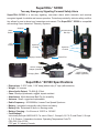
SuperCELL® SC500
Two-way Emergency Signaling Personal Safety Alarm
SuperCELL® SC500 is a two-way signaling, man-down alarm which transmits and receives
encrypted signals for reliable and secure operation. Protection provided by intrinsic safety certification allows for use in almost any hazardous environment. The SuperCELL® SC500 is compatible
with existing Grace Industries’ Telemetry Systems.
Antenna
Multi-directional
Belt Clip
Alarm
Button
LCD
Display
Operation
Controls
Operation
Controls
Charging Contacts
Sound Port
120VAC Charger
Adapter (Standard)
12VDC Charger
Adapter (Optional)
Charging Base
SuperCELL® SC500 Specifications
•
•
•
•
•
•
•
•
•
•
•
Dimensions: 2-3/16” wide, 1-3/8” deep (without clip), 4” high (with antenna).
Weight: 5.6 ounces.
Alarm Audio Output: 75 dBA @ 10 feet.
Case: Black polycarbonate, rugged, impact resistant.
Attachment: Multi-directional Belt Clip for versatility.
Antenna: Small, rugged and replaceable.
Radio Frequency: 902-928MHz, License Free Spread Spectrum.
Battery: Integrated, intrinsically safe Lithium-ion battery.
Battery Life: Estimated 80 hours in Sensing mode.
Battery Charging: 6 to 8 hours at 12VDC or 120 VAC
Certifications:
Intrinsically Safe per ANSI/UL913. For use in Class 1, Groups A, B, C & D; and Class II, Groups
E, F, G: Division 1 Hazardous locations. Operating Temperature Code T6.
CSA C22.2 No.157-92.
FCC part 15, Industry Canada.
42
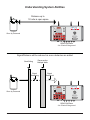
Understanding System Abilities
Distance up to
1/2 mile in open space
ALARM
LOCAL
RX
POWER
TX
REMOTE
TX
o
o
o
o
o
o
o
o
o
o
o
o
o
o
o
o
o
o
o
o
o
o
o
o
o
o
o
o
o
o
EXIT
o
ENTER/
SELECT
PLAY/
STOP
o
MENU
o
AUDIO
TONE
o
VOLUME
RECORD
o
VOLUME
o o
o
AUX
o
o
F3
o
o
o
F2
o
o
o
o
o
F1
POWER
o
o
o
o
o
MICROPHONE
o
RX
BATTERY
TPASS®
Worn by Personnel
Grace Industries, Inc.
Safety Monitoring System
Fredonia, PA 16124 USA
G.E.M.S. BY GRACE IND., INC.
TP-HP-M-XX12080002
))
GEMS SMS Base
4 to 5 feet off the ground
Signal/Distance will be reduced as more obstacles are added
Dense and/or
Multiple Walls
Signal
Diminished
ALARM
LOCAL
RX
POWER
TX
REMOTE
TX
o
o
o
o
o
o
o
o
o
o
o
o
o
o
o
o
o
o
o
o
o
o
o
o
o
o
o
EXIT
Grace Industries, Inc.
Safety Monitoring System
Fredonia, PA 16124 USA
G.E.M.S. BY GRACE IND., INC.
TP-HP-M-XX12080002
))
GEMS SMS Base
4 to 5 feet off the ground
43
o
PLAY/
STOP
o
AUDIO
TONE
o
RECORD
ENTER/
SELECT
o
AUX
MENU
o
VOLUME
o
o
VOLUME
o o
o
F3
o
o
o
F2
o
o
o
o
o
F1
POWER
o
o
o
o
o
o
RX
BATTERY
MICROPHONE
o
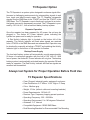
TPASS®
Worn by Personnel
o
Signal
Weakening
o
Steel Siding
T3 Repeater Option
The T3 Repeater is a system option designed to enhance signal effectiveness in challenging environments by retransmitting signals to and
from tough and hard-to-reach areas. The T3 Repeater retransmits
signals from the SMS Base to the TPASS® and from the TPASS® to the
SMS Base. The T3 Repeater is omni-directional, enclosed in an industrial grade case and is permanently mounted. The T3 Repeater is powered by 120 Volt A.C., with a lead acid battery backup system.
Repeater Operation
Once the repeater has been prepared for AC power, the unit may be
plugged in. The Amber AC Power Indicator glows indicating the
system has power and is ready for operation.
A Red Activity Indicator light is located on the bottom left of the
repeater. The Activity Indicator will flash when signals are received
from a TPASS® or the SMS Base and are retransmitted. Operation may
be checked by manually activating a TPASS® and watching the Activity
Indicator light on the bottom of the repeater for flashes.
Backup Power Supply
The lead acid battery system will automatically provide approximately
50 hours of continuous operation with the loss of 120 Volt A.C. With
loss of power, the Amber AC Power Indicator will not glow. The backup
battery system is automatically activated keeping the repeater ON and
ready for operation. The Red Activity Indicator will flash as signals are
received and transmitted.
Always test System for Proper Operation Before Field Use
T3 Repeater Specifications
• Case: Rugged, industrial grade, waterproof enclosure
• Case Dimensions: 6.5" Wide x 14.25" High x 4" Deep
• Color: Medium gray
• Weight: 10 Lbs. (without cable and mounting brackets)
• Power Requirements: 120 Volt A.C.
• Receiver Type: Frequency hopping spread spectrum
• Operating Frequency: 902 - 928 MHz
• Operating Environment: 0 to 140 degrees Fahrenheit
• Antennas: 3.5" Internal
• Compatible Equipment: GEMS SMS Base
• Dual Mounting Brackets for Recommended Pole Mounting
44
T3 Repeater Option
(continued)
T3 Repeater will retransmit the signal and
enhance system ability in challenging environments
T3 Repeater
Signal
Diminished
ALARM
LOCAL
RX
POWER
TX
REMOTE
TX
o
o
o
o
o
o
o
o
o
o
o
o
o
o
o
o
o
o
o
o
o
o
o
o
o
o
o
o
EXIT
Grace Industries, Inc.
Safety Monitoring System
Fredonia, PA 16124 USA
G.E.M.S. BY GRACE IND., INC.
TP-HP-M-XX12080002
))
GEMS SMS Base
4 to 5 feet off the ground
45
o
PLAY/
STOP
o
AUDIO
TONE
o
RECORD
ENTER/
SELECT
o
AUX
MENU
o
VOLUME
o
o
VOLUME
o o
o
F3
o
o
o
F2
o
o
o
o
o
F1
POWER
o
o
o
o
o
o
RX
BATTERY
MICROPHONE
o
TPASS®
Worn by Personnel
o
Signal
Weakening
ed
eiv
ec
lR
Sig
na
na
Steel Siding
Dense and/or
Multiple Walls
Sig
lS
en
t
NOTE: Hardware and
Recommended PoleMounting Instructions
Included with T3 Repeater
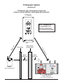
Remote Enhanced Radio Receiver Option
The Remote Enhanced Radio Receiver may provide a significant
enhancement to signal reception in tough or hard-to-reach areas,
enabling the SMS Base to operate more effectively and provide better
service.
Receiver Setup
For optimum performance, mount the Remote Enhanced Radio
Receiver as high as possible and away from metallic objects.
The Remote Enhanced Radio Receiver may be mounted up to 100
feet above SMS Base. This allows for easier, unobstructed reception
of signals.
The SMS Base must be OFF when connecting the enhanced
receiver. The Remote Enhanced Radio Receiver quickly and easily
plugs into bottom of SMS Base.
Once connected, turn the SMS Base ON and the Remote Enhanced
Radio Receiver is operational. The Remote Enhanced Radio Receiver
should always be used with the SMS Base for maximum effectiveness.
Always test System for Proper Operation Before Field Use
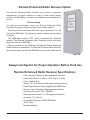
Remote Enhanced Radio Receiver Specifications
• Case: Rugged, industrial grade, waterproof enclosure
• Case Dimensions: 6.5" Wide x 14.25" High x 4" Deep
• Color: Medium gray
• Weight: 1 lb, 9 oz. (without cable and mounting brackets)
• Power Requirements: Power supplied from SMS Base
• Receiver Type: Frequency hopping spread spectrum
• Operating Frequency: 902 - 928 MHz
• Operating Environment: 0 to 140 degrees Fahrenheit
• Antennas: 3.5" Internal
• Compatible Equipment: GEMS SMS Base
• 100 ft Cable
• Mounting Bracket
46
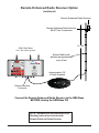
Remote Enhanced Radio Receiver Option
(continued)
Remote Enhanced Radio Receiver
Remote Enhanced Radio Receiver
MUST Face Transmitters
15' - 20'
GEMS SMS Base
4 to 5 feet off the ground
Secure Cable to pole
with wire-ties approximately
every 4 feet.
ALARM
LOCAL
RX
POWER
TX
REMOTE
TX
o
o
o
o
o
o
o
o
o
o
o
o
o
o
o
o
o
o
o
o
o
o
o
o
o
o
o
o
o
EXIT
))
o
ENTER/
SELECT
o
PLAY/
STOP
o
MENU
o
AUDIO
TONE
o
VOLUME
RECORD
o
VOLUME
o o
o
AUX
o
o
F3
o
o
o
F2
o
o
o
o
o
F1
POWER
o
o
o
o
o
o
RX
BATTERY
MICROPHONE
Grace Industries, Inc.
Safety Monitoring System
Fredonia, PA 16124 USA
G.E.M.S. BY GRACE IND., INC.
TP-HP-M-XX12080002
Approximately 100'
of Cable Supplied
Remote Receiver
Connector
Connect the Remote Enhanced Radio Receiver to the SMS Base
BEFORE turning the SMS Base ON
NOTE: Hardware and Recommended PoleMounting Instructions Included with
Remote Enhanced Radio Receiver
47
Locator Transponder
Locating & Tracking Sensor
Personnel may be located by deploying wireless
Locator-Transponders throughout buildings. The
Locator-Transponder is a small, battery powered
sensor that transmits location when a monitoried
individual approaches the detection area of a
Locator-Transponder.
The wearer’s monitoring device periodically transmits the last location, along with the wearer’s status
to the SMS-AT. If an Alarm Condition is triggered,
(through Emergency Alarm button or Lack-ofMotion) the Alarm Signal and Location are transmitted to the SMS-AT so supervisors or safety personnel are alerted and can respond to the exact location.
Always test System for Proper Operation Before Field Use
Locator-Transponder Specifications
• Model: LT100-L
• Battery: powered by one AA (3.6 volt) lithium-ion battery
• Size: 2-9/16” x 2-9/16” x 1-5/8”
• Color: Medium gray
• Weight: 5.8 ounces
• Frequency: 902 - 928 MHz (frequency hopping and spread spectrum)
• Compatibility: SuperCell® SC300, SC500 and TPASS®3 (Locator Models)
• Mounting Bracket
48
Programmable Telephone Dialer Option
Plugs into
power-in jack
Power-In Jack
Automatic
Telephone
Dialer
12 VDC
Power
Supply
6’ Telephone Jack Cable:
Plugs Into Automatic
Telephone Dialer
6’ Cable with
5-pin connector that
plugs into Relay Contact
Connector of SMS Base
Aux Panel
Plugs into
Telephone Wall Jack
Plugs into telephone wall jack
NOTE: Instruction Manual Included.
ALARM
LOCAL
RX
POWER
TX
REMOTE
TX
Automatic Voice/Pager Dialer
o
o
o
o
o
o
o
o
o
o
o
o
o
o
o
o
o
o
o
o
o
o
o
o
o
o
o
o
o
EXIT
o
ENTER/
SELECT
o
PLAY/
STOP
o
MENU
o
AUDIO
TONE
o
VOLUME
RECORD
o
VOLUME
o o
o
AUX
o
o
F3
o
o
o
F2
o
o
o
o
o
F1
POWER
o
o
o
o
o
o
RX
BATTERY
MICROPHONE
Plugs into
120 VAC
wall outlet
Grace Industries, Inc.
Safety Monitoring System
Fredonia, PA 16124 USA
G.E.M.S. BY GRACE IND., INC.
TP-HP-M-XX12080002
))
Plugs into Relay Contact Connector
of SMS Base Aux Panel
49
NOTES:
_________________________________________________________________
_________________________________________________________________
_________________________________________________________________
_________________________________________________________________
_________________________________________________________________
_________________________________________________________________
_________________________________________________________________
_________________________________________________________________
_________________________________________________________________
_________________________________________________________________
_________________________________________________________________
_________________________________________________________________
_________________________________________________________________
_________________________________________________________________
_________________________________________________________________
_________________________________________________________________
_________________________________________________________________
_________________________________________________________________
_________________________________________________________________
_________________________________________________________________
_________________________________________________________________
_________________________________________________________________
_________________________________________________________________
_________________________________________________________________
_________________________________________________________________
_________________________________________________________________
_________________________________________________________________
WARRANTY
Grace Industries, Incorporated warrants your Product to be free from defects in workmanship and
materials for a period of one year from the date of purchase. This warranty is valid only when the
returned Product is accompanied by a sales slip or other proof of purchase that states the date and
location of purchase. Grace Industries, Inc. will not repair or replace any merchandise that has been
damaged because of accident, misuse or abuse of the Product while in the possession or control of
the consumer. This warranty is void if any attempt to repair or replace parts was made or attempted
by other than qualified Grace Industries, Inc. personnel. This warranty is void if any of the sealed
compartments are opened or tampered with. Send all returned merchandise prepaid and accompanied by proof of purchase to: Grace Industries, Inc., Repair Division, 305 Bend Hill Road, Fredonia,
PA 16124. Grace Industries, Inc. shall not be liable for any direct, incidental or consequential loss or
damage arising out of the failure of the device to operate.
The sole and exclusive remedy under all guarantees or warranties, expressed or implied, is strictly
limited to repair or replacement as herein provided. ALL IMPLIED WARRANTIES, INCLUDING BUT
NOT LIMITED TO, WARRANTIES OF FITNESS AND MERCHANTABILITY, ARE HEREBY LIMITED IN DURATION TO A PERIOD ENDING ONE (1) YEAR FROM THE DATE OF PURCHASE.
The warranty and liability set forth in the prior paragraphs are in lieu of all other warranties,
expressed or implied, in law or in fact, including implied warranties of merchantability and fitness for
a particular purpose. Some states do not allow limitations on how long an implied warranty lasts, so
the above limitations may not apply to you.
This warranty gives you specific legal rights and you may also have other rights which vary from
state to state.
NOTE: The information contained in this booklet is believed to be accurate and reliable. Grace
Industries, Inc. provides this information as a guide only.
305 Bend Hill Road, Fredonia, PA 16124 USA
724.962.9231 - FAX 724.962.3611
www.graceindustries.com
© 2012-2013, Grace Industries, Inc.
ALWAYS TEST SYSTEM PRIOR TO USE!
All personnel should be thoroughly familiar with and trained in the proper
operation of Personnel Monitoring System prior to field use. Failure to do so
may expose the user to serious injury or loss of life.
Printed in U.S.A.
GEMS SMS-AT UI 070113
305 Bend Hill Road, Fredonia, PA 16124
724.962.9231 - FAX 724.962.3611
www.graceindustries.com