1
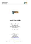
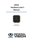
3JTech 2.4 GHz FHSS
Master/Slave Wireless
RS232 / IrDA
User’s Manual &
Programming Guide
Revision 1.3
3J Tech Co., Ltd.
342 Fushing N. Rd., 2F
Taipei, Taiwan
A3J Eng. Inc.
15344 E Valley Blvd., Suite C
City of Industry, CA 91746 USA
3J Tech. Co., Ltd.
Revision History
Revision
Date
Changes
1.0
1.1
1.2
1.3
2002/1/11
3/6/01
3/9/01
8/11/01
First Release (PP)
Corrected # of slave devices, added more info regarding RS-232 specs. (HH)
Added section on testing. (HH)
Change 8,N,2 to 8, N, 1
Revision 1.0
2
3J Tech. Co., Ltd.
Table of Contents
1.
INTRODUCTION...................................................................................................................................................... 4
2.
SYSTEM FEATURES ............................................................................................................................................... 5
3.
INTENDED USES...................................................................................................................................................... 5
4.
RS-232 SERIAL LINE SPECIFICATION .............................................................................................................. 6
5.
MASTER-SLAVE LOCKING AND CONNECTION............................................................................................ 6
6.
COMMUNICATION BETWEEN PC-APPLICATION & MASTER WM ......................................................... 7
6.1 Slave Configuration Commands............................................................................................................................. 7
6.2 Connection Commands .......................................................................................................................................... 7
6.3 Status Inquiry Commands ...................................................................................................................................... 7
7.
COMMUNICATION BETWEEN RS232_DEVICE & SLAVE WM ................................................................... 8
8.
TESTING OF THE WM SYSTEM.......................................................................................................................... 8
9.
EXAMPLE OF PROGRAMMING WIRELESS MODEMS USING 3JTECH'S CAMIT ............................... 10
9.1 Introduction......................................................................................................................................................... 10
9.2 Setting up the equipments.................................................................................................................................... 14
9.3 Running the test tool............................................................................................................................................ 14
10.
COMMUNICATION PROTOCOLS ..................................................................................................................... 18
10.1 Background ........................................................................................................................................................ 18
10.2 Description......................................................................................................................................................... 18
10.3 Procedures ........................................................................................................................................................ 18
10.4 Illustrations ........................................................................................................................................................ 19
Revision 1.0
3
3J Tech. Co., Ltd.
1. Introduction
This document presents the user’s manual and programming guide for a digital 2.4 GHz frequency
hopping spread spectrum wireless expansion module for RS232 and IrDA in master and slave mode.
The main purpose of this device is to extend the range of RS232 and IrDA communication as well as
providing a multipoint environment.
Revision 1.0
4
3J Tech. Co., Ltd.
2. System Features
•
•
•
•
•
•
•
•
•
•
•
•
•
•
•
•
•
2.4 GHz Frequency Hopping Spread Spectrum
One 115.2Kbit full duplex channel
Point to Multi-point communication
Range 2000 Feet (line of sight)
115.2Kbit RS-232 port
115.2Kbit IrDA port (Firmware available in 3Q, 2001)
3 AAA battery cells
External AC power supply
Built in battery charging
LED for link verification
Robust FHSS and TDMA wireless protocol
Operation time 8 hours
Standby time one week
12 points of wireless connection
Master / Slave configuration switch
Master is programmed to connect to slaves
Easy add on of extra slaves
3. Intended Uses
The complete system is intended as a component to be used by a product developer in constructing
other complete systems or products. It is not intended to be offered as a stand-alone product, for
retail sale. 3JTech also sell a stand-alone product, which is called RF232 for direct replacing
RS232 cable. RF232 is sold as a pair of wireless modem. This document describe the usage and
programming for the master/slave mode wireless communication through serial ports. When
incorporating this system into a product, or when offering the system as an accessory to a product, the
product developer must take responsibility for verifying that the entire system (product plus Wireless
Modem sub-system) will operate as intended. Such responsibility would include testing the complete
system, specifying resulting operational characteristics, modifying the product’s hardware or
software to be compatible with the Wireless Modem, and possibly, modifying the Wireless Modem
hardware or software to accommodate additional requirements of the finished product.
Revision 1.0
5
3J Tech. Co., Ltd.
4. RS-232 Serial Line Specification
The RS-232 communications interface supports a specific subset of protocols and capabilities of a
serial line. The following requirements constrain the type of RS-232 communications supported by
the Wireless Modem.
1. Baud Rate – Fixed at 115200 bits per second. Changing baud rate, including auto-baud
detection is not supported.
2. Character format – Fixed at N-8-1 (No parity, 8 data bits per byte, and 1 stop bits).
3. Terminal Type – Fixed as a DCE (for both Master and Slave).
4. Connector type – 9-Pin Mini-Sub-D (female) for both Master and Slave.
5. Flow Control – Hardware flow control (RTS/CTS) is required. PC must monitor CTS and
stop sending data when the Wireless Modem de-assertes CTS. The Wireless Modem
monitors RTS asserted by the PC, as well.
6. Data transparency – The data sent over the link may contain any valid 8-bit character
sequence, when the device is in Connected (Data) mode. In Data mode, the device does not
attempt to interpret the data in the stream. In Command mode, only valid commands may be
sent to the device.
5. Master-Slave Locking and Connection
In this section we discuss the concepts of Master and Slave devices, and the concepts of locking and
connecting.
A Wireless Modem may be configured as either a Master or a Slave, by switching a mechanical
switch. Connections may only be made between a Master and a Slave. That is to say that two slaves
can not connect, or send data between each other. A given Master may connect to only one Slave at a
time, although multiple Slaves may be “locked” to the same Master. A Slave can only lock to one
Master.
“Locking” and “connecting”are two important concepts related to the establishment of connections
between Wireless Modems. “Locking” refers to listening to another device, or being prepared to
make a data connection. “Connecting” refers to actually making a data connection to another device.
Only Slave devices lock to a Master. Slaves do not lock to other Slaves, and Master devices do not
lock, and usually, they are unaware of the lock status of their own Slaves. A Slave may only lock to
one Master at a time. The Slave will remain locked to that Master until it looses RF contact with that
device. Once it looses RF contact, it will try to find a Master to lock to.
In order to make a connection between a particular Slave and a Master, the Slave must already be
locked to that Master. A Slave may only connect to a single Master, which is the Master that it is
locked to. The Slave determines which Master to lock to by listening for its own (the slave’s) serial
number to be broadcast by a Master. The Slave will lock to whichever Master broadcasts the slave’s
address. Therefore, it is a configuration error to configure more than one Master to control the same
Slave. If a Slave does not detect its own serial number broadcast in a certain time period, it will put
itself to sleep temporarily and try again later. A Master may have up to 12 slaves locked to it, at any
point in time.
Revision 1.0
6
3J Tech. Co., Ltd.
A connection may be initiated by either the Master or a Slave, by sending AT commands to the
Wireless Modem over the RS-232 interface, and by asserting the DTR pin. The commands and
protocol used by the Master differ from those used by the Slave. Of course, if a connection is already
in progress between the Master and another slave, a connection attempted by a slave will be rejected
by the Master. The Master will not attempt a 2nd connection when there is already one in progress.
6. Communication between PC-Application & Master WM
In the discussion that follows, we assume that a PC is connected to a Master, and that there are
multiple RS232_Devices, each connected to a Slave. The PC may control the establishment of
connections between the Master WM and the various Slaves. The communication protocol used has
a format similar to ordinary modem AT commands. All of the commands are sent using the same
serial line discipline as for data mode: N-8-1, 115200 bps.
There are 3 types of messages, or commands exchanged between the PC and the Master WM. These
are slave configuration commands, status inquiry commands, and connection commands.
Slave ID Configuration Commands (for Master)
The PC informs its WM of the various slaves that should be locked to it. The PC sends the following
command to tell the PC that the indicated slave should lock to this master:
AT&Zn=xxxxx<CR> -- Store slave serial number. Where n is the nth slave serial number (0-B)
-- The response is OK<CR> or ERROR<CR>
The PC informs the WM that it should no longer retain a certain slave by issuing the same command
with the slaveID set to all zeros:
AT&Zn=00000<CR>
Connection Commands
The PC instructs its WM to connect to a particular slave by issueing the command:
ATD xxxxx<CR>
-- Dial to the slave wireless modem. It will be followed by DTR high to start
the dialing.
-- The response is OK<CR> or ERROR<CR>
The PC Answers the incoming call request from one of the slaves by driving DTR high.
Status Inquiry Commands for Master
ATI0<CR>
-- View Serial Number. WM will respond with Master WM’s serial number.
-- The response format is SN xxxxx<CR>.
ATI3<CR>
-- View ROM version. WM will respond with version and build date.
Revision 1.0
7
3J Tech. Co., Ltd.
-- The response format is REV bbbbyymmdd<CR> where bbbb is build
-- number, yy is year, mm is month, and dd is day.
Note that xxxxx is slave serial number ( 5 bytes ) and <CR> is hexdecimal number 0x0d. Invalid
command will get ERROR<CR> response from the WM.
7. Communication between RS232_Device & Slave WM
The communication between the RS232_Device and the Slave WM is much simpler than that
between the PC application and the Master WM. Whereas the Master WM may accept connections
from multiple slaves, a particular slave may only connect to its own master. This constraint means
that it is not necessary for the slave WM to specify the target of a connection request. Likewise, the
slave WM does not need to specify the origin of an incoming connection request. Please see the
section on Handshaking for more information.
Connection to Master Command for Slave
The device connected to a Slave WM does not send an AT command to cause the WM to connect to
the Master. Instead, it simply drives DTR high, and waits for DCD to go high to signal a successful
connection.
Status Inquiry Commands for Slave
ATI0<CR>
-- View Serial Number. WM will respond with serial number.
-- The response format is SN xxxxx<CR>.
S0?<CR>
-- Slave host queries "LOCK" status to see if we have locked to a host WM.
-- If locked, send back LOCK<CR> else NO LOCK<CR>.
ATI3<CR>
-- View ROM version. WM will respond with version and build date.
-- The response format is REV bbbbyymmdd<CR> where bbbb is build
-- number, yy is year, mm is month, and dd is day.
Note that xxxxx is slave serial number ( 5 bytes ) and <CR> is hexdecimal number 0x0d. Invalid
command will get ERROR<CR> response from the WM.
8. Testing of the WM System
Although final testing of the complete system is the responsibility of the customer, a certain degree of
testing has been performed to ensure a minimum level of quality and development risk.
The Wireless Modem system has been tested in the following areas:
• Stability of individual WM units (software & hardware)
• Stability of connection and handshaking protocol
• Reliability of slave locking protocol
• Operation with multiple simulated RS232_Devices
Revision 1.0
8
3J Tech. Co., Ltd.
•
•
•
•
•
•
•
Compatibility with PC RS-232 port
Compatibility with sample test application
Standby battery life
Active battery life
Raw data throughput (tested by transferring large files using Z-Modem protocol)
Performance under degraded RF reception conditions
FCC Part 15 compliance (unofficial testing)
A complete description of the testing process is beyond the scope of this document. Instead, the
following sections give some general information about the nature of testing performed.
For all of the tests except for the FCC Part 15, the test environment was as follows:
3JTech has developed a PC application (in Visual BASIC), which simulates the operation of the
RS232_Device and of the controlling application. The application may be used to exercise the WM
system in a variety of ways. The number of slave WM’s that may be included in the test proceedure
is limited by the number of serial ports on the PC (or the number of PC’s). Of course, for RF range
testing, it is necessary to have more than one PC. Each instance of the test application controls only
one WM (either Master or Slave), and is not able to cooperate with other instances of the test
application. Therefore, a human operator is required to operate the application to run the test cases.
A brief description of the test cases follows:
•
Stability of individual WM units (software & hardware)
Tested by placing and disconnecting multiple data connections, over an extended
period of time (2 days).
•
Stability of connection and handshaking protocol
Tested by placing and disconnecting multiple data connections, over an extended
period of time (2 days).
•
Reliability of slave locking protocol
Tested by repeatedly power-cycling a slave WM, repeated for master.
•
Operation with multiple simulated RS232_Devices
Tested by placing and disconnecting multiple data connections, and transferring files
using Z-Modem file transfer protocol.
•
Compatibility with PC RS-232 port
Inferred from successful testing using a PC.
•
Compatibility with sample test application
Inferred from successful testing using the application.
Revision 1.0
9
3J Tech. Co., Ltd.
•
Standby battery life
Measured for one unit by monitoring it every 6 hours. Details of battery used in test
will be specified. Unit-to-unit variability not tested.
•
Active battery life
Measured for one unit by leaving it operating in data connection mode. Details of
battery used in test will be specified. Unit-to-unit variability not tested.
•
Raw data throughput (tested by transferring large files using Z-Modem protocol)
Data rates for uni-directional and bi-directional transfers will be stated. Data rates at
various levels of RF signal quality will be stated.
•
Performance under degraded RF reception conditions
Slave locking, connection request, re-establishment of link, and throughput will be
tested.
•
FCC Part 15 compliance (unofficial testing)
This test is designed to generate confidence that the design will pass official FCC
testing. It is not a substitute for actually performing the official tests.
Revision 1.0
10
3J Tech. Co., Ltd.
9. Example of Testing Wireless Modems using 3JTech's CAMit
9.1 Introduction
This test tool is designed to test the 3JTech Wireless Modem (WM) for CAMIt product. A basic test
configuration is illustrated below:
Modem
Desktop System
Modem
Modem
Modem
Desktop System
In the above diagram, the top PC controls the Master WM and the bottom PC controls three Slave
WMs. The top PC downloads the slave WM Slave IDs to the Master WM which then broadcasts the
IDs periodically. When a Slave WM starts up, it scans for a Master that broadcasts its ID and locks to
that Master. A PC application program is used here to simulate a camera for testing purpose.
Test Application for controlling the Master WM: Notice that the application queries the serial
number and build information from the WM when the COM port is opened. The window title bar is
updated with the serial number.
Revision 1.0
11
3J Tech. Co., Ltd.
Test Application for controlling the Slave WM: Notice that the application queries the serial
number and build information from the WM when the COM port is opened. The window title bar is
updated with the serial number. Test application will periodically query the “LOCK” status from the
WM slave. If the Slave WM can still hear from its Master, “LOCK” reponse will be returned,
Otherwise, “UNLOCK” status is returned.
Slave ID Broadcast - The slave IDs are broadcasted periodically by the Master WM. Every 640
msec, the next slave ID in the slave ID list is transmitted. Since a single Master WM can control up to
12 Salve WMs, a slave will be able to hear its ID no later than 7.68 seconds (0.64 sec/slave ID * 12
slave IDs). For example, if there are three slave IDs in the list, any one of the slaves will hear its ID
Revision 1.0
12
3J Tech. Co., Ltd.
within 1.92 seconds (0.64 sec/slave ID * 3 slave IDs). However, after power-on, locking may take
longer than 7.68 seconds, because the slave must find the correct hop channel before the locking
process may begin.
Handshaking Protocol - The handshaking protocol between PC/camera and WM is defined in
3JTech Serial Line Handshaking Protocol Proposal document.
LED indicators – Three LED indicators are used to show the operating status of the WM boards.
LED 1 – “I Am Alive” indicator. This LED flashes once per second to indicate that the
application code is running.
LED2 – “Data Mode” indicator. When a call is established between a Master WM and a Slave
WM, this LED flashes once per second. When in data mode, data exchange can take place.
LED3 – “Locked” indicator. This is only used by the Slave WM to indicate that it has found its
Master WM and it is locking to it.
Visual Basic Test application program - The PC application program is written in Microsoft Visual
Basic. It implements the handshaking protocol required to instruct WM to set up and tear down a call.
The idea is to use it as a debugging tool during the firmware development and also as a reference for
vendor’s real host application development. Visual Basic has been chosen for fast prototyping and
ease of learning.
Commands and responses between Test application program and WM Valid commands for Master WM are:
ATD xxxxx<CR>
-- Dial to the slave wireless modem. It will be followed by the PC driving
DTR high to start the dialing.
-- The response is OK<CR> or ERROR<CR>
AT&Zn=xxxxx<CR> -- Store slave serial number. Where n is the nth slave serial number (0-B)
-- The response is OK<CR> or ERROR<CR>
ATI0<CR>
-- View Serial Number. WM will respond with Master WM’s serial number.
-- The response format is SN xxxxx<CR>.
Revision 1.0
13
3J Tech. Co., Ltd.
ATI3<CR>
-- View ROM version. WM will respond with version and build date.
-- The response format is REV bbbbyymmdd<CR> where bbbb is build
-- number, yy is year, mm is month, and dd is day.
Valid commands for Slave WM are:
ATI0<CR>
-- View Serial Number. WM will respond with serial number.
-- The response format is SN xxxxx<CR>.
S0?<CR>
-- Slave host queries "LOCK" status to see if we have locked to a host WM.
-- If locked, send back LOCK<CR> else NO LOCK<CR>.
ATI3<CR>
-- View ROM version. WM will respond with version and build date.
-- The response format is REV bbbbyymmdd<CR> where bbbb is build
-- number, yy is year, mm is month, and dd is day.
Note that xxxxx is slave serial number ( 5 bytes ) and <CR> is hexdecimal number 0x0d. Invalid
command will get ERROR<CR> response from the WM.
9.2 Setting up the equipments
9 Pin RS-232 Cables - Connect one end to the PC COM port and another end to the WM COM port.
Power Supply – Adjust the voltage to 7.6 V and connect the power adapter connector to the WM.
** Note that this is applicable to the prototype WM board with ewd 8010 processor only ****
Reset Button – After applying the power, press the reset button to start running the firmware. The “I
Am Alive” LED indicator will start to flash once per second.
*** Note that the production version WM will not need this reset button. ****
Firmware – Correct version of firmware must be loaded on the Master WM and Slave WMs.
*** Note that the production version of 3JTech WM will have single flash memory containing ***
*** both Master and Slave firmware and the selection is determined by the DIP switch setting. ****
Distance between Master WM and Slave WMs – Adjust to proper distance for testing.
9.3 Running the test tool
vbterm_master.exe – This program simulates a PC host application that controls the Master WM.
vbterm_slave.exe – This program simulates a camera that controls the Slave WM.
Revision 1.0
14
3J Tech. Co., Ltd.
Select the COM port – Use the above two programs to select the COM port.
CommPort -> Port
Configuring the PC COM port – Use the above two programs to set the corresponding COM port
to the following settings: CommPort -> Property -> Maximum Speed and Connection Preferences.
115200 baud, 8 bits, no parity, 1 stop bits.
Hardware Flow Control – Use the above two programs to turn on the hardware flow control.
CommPort -> Property -> Flow Control -> RTS
Status Indicators and Control buttons – There are a few status indicators on the upper area of the
application GUI. Red color indicates that the status is “not asserted” and green color indicates that the
status is “asserted”. DTR and RTS are used as both status indicator and control button. CTS and
DCD are status indicators only. You can click on the control buttons to toggle the state of it.
DTR (Data Terminal Ready) – Use this button on Slave host application to connect and
disconnect from the Master. On Master, use “Dial phone
number” button to connect to one of the slaves and use DTR to
disconnect from the slave.
RTS (Request to Send) – RTS is used to assert and deassert the RTS pin on the PC COM
port.
This control button is not effective when the hardware
flow control is turned on. Turn the hardware flow control off
when you need to manually control the state of the RTS pin.
CTS (Clear to Send) – WM firmware asserts CTS to the PC to indicate that it is ready to
receive more data from PC. If hardware flow control is turned
on,
DCD (Data Carrier Detect) – The status is to indicate the handshaking status during call
setup and termination.
COM port control button – The control button is used to open and close PC COM port.
Host application opening the PC COM port – Click on the COM port control button to open the
COM port. The following status indicators will be updated:
CTS status indicator turns green to indicate that WM is connected to the PC COM port.
RTS status indicator turns green to indicate PC is ready to accept input from WM.
Revision 1.0
15
3J Tech. Co., Ltd.
Master connects to Slave – Use the Dial Phone Number button (The 3rd from the left) to select the
slave ID to connect to and click on OK button to start the connection. The following status
indicators will be updated if connection is successful:
DTR on Master turns green to indicate that call request has been made to Master WM.
DCD on Master turns green to indicate that call request is acknowledged by the Master WM.
DCD on Slave turns green to indicate that call request is present.
DTR on Slave turns green to indicate that Slave has accepted the call from the Master.
If the connection is not successful, a message box “Timeout on DCD” will appear after
5 seconds.
Slave connects to Master – Use the DTR button to connect to the Master. The following status
indicators will be updated if connection is successful:
DTR on Slave turns green to indicate that call request has been made to Slave WM.
“Ring” with slave ID appears on Master scrolling window area to indicate that the slave
is calling the master.
DTR on Master turns green to indicate that Master has accepted the call from the Slave.
DCD on Master turns green to indicate that call request is acknowledge by the Master WM.
DCD on Slave turns green to indicate that call request has been accepted by the Master.
If the connection is not successful, a message box “Timeout on DCD” will appear after
5 seconds.
Call Termination – Use the DTR button to disconnect the call. When the call is terminated, the
Status indicators will be updated. Both DCD and DTR status indicators turns red to indicate
Signal is deasserted.
Log screen contents -Screen contents can be logged to a file. This feature can be used for
comparing the text file transfer result. See below.
Key input and screen display – After a connection is established between the Master and a slave,
key input on one end of the connection will be displayed on the other end. Use Comport properties ->
Echo on to allow local echoing. If there is no connection available, key input will not be sent to the
other end.
Text File Transfer – After a connection is established between the Master and a Slave, text file
transfer can take place. VB application will scroll the text received on its window. You can
log the screen contents from the start to the end of the file transfer and do file compare to
verify the file transfer result.
Revision 1.0
16
3J Tech. Co., Ltd.
** Note ** Be sure to turn on hardware flow control before doing the file transfer.
Also, VB application can be modified to just capture the received data and
save it to a file directly. Thus, binary file transfer can be accomplished.
Revision 1.0
17
3J Tech. Co., Ltd.
10. Communication Protocols
10.1 Background
The Wireless Modem project uses wireless modems to replace cables carrying data and control
information between several digital RS232_Devices and a controlling application hosted on a PC.
Because the application and the RS232_Devices must be able to properly control the wireless
modems, the system requires a suitable communication protocol between the application and the
master modem, and between the RS232_Devices and the slave modems.
10.2 Description
The current description concerns the use of serial line RS-232 signals and messages for the
purpose of controlling the wireless modems. At any one moment, only one slave modem may
have a connection to the master. As a result, the controlling application must take responsibility
for contacting each slave in turn to determine if it has data. In this case, the slave modem
(connected to the RS232_Device) must inform the RS232_Device that a connection has been
established. In addition, either the PC application or the RS232_Device must terminate the
wireless connection whenever there is no data remaining to be sent on the connection. When a
RS232_Device acquires new data that it wishes to send, it may initiate a connection to the
application. In such a case the master wireless modem (connected to the master) must inform the
application that a connection has been made, and to which slave (RS232_Device). To summarize,
either side (RS232_Device or PC) may initiate a connection, and either side may terminate an
active connection.
Of course, a RS232_Device initiating a connection may only connect with the PC. This means
that a slave WM will connect with the master WM. The RS232_Device need not inform its WM
where to make the connection, because there is only one possibility. However, the master WM
must inform the PC which RS232_Device has just initiated a connection.
The scenario where the PC initiates the connection raises different requirements: The PC must
instruct its WM (the master) which slave to connect to. The slave WM must inform its connected
RS232_Device that a connection has just been established to the PC.
10.3 Precedures
10.3.1. General
First, PC and RS232_Device should drive DTR high to command the attached (local) WM to
establish a connection, and low to issue a command to tear down a connection. The WM should
drive DCD high to indicate a successful connection establishment, and low to indicate a
connection tear down.
10.3.2. Use of "AT" Commands for Communication of Slave Serial #'s
Revision 1.0
18
3J Tech. Co., Ltd.
In addition to the signals DTR and DCD, the PC application should issue and receive certain
specific "AT" commands during the period when DTR is low. The following AT commands will
be used. "ATD <slave serial #><CR>" will be sent by the master to indicate to which a
connection is desired. The slave serial number will be specified as 5 hexadecimal digits (e.g.,
123AB). The PC's WM will respond with "OK<CR>", if the command was understood. After
OK is received from the WM, the PC should drive DTR high to initiate the connection. When a
slave WM initiates a connection, the PC's WM (the master) should issue the message "RING
<slave serial #><CR>" to inform the PC from which slave (RS232_Device) to expect a
connection. The master WM will only accept the connection if the PC drives DTR high.
10.3.3 Timing Details
10.3.3.1 Connection Initiated by PC
In this case the following sequence of events should occur:
1. Initially, the WM on the PC side holds DCD low, and the PC holds DTR low, because there is
no connection.
2. The PC issues the following command: ATD xxxxx<CR> (xxxxx = slave serial #)
3. The PC's WM responds with OK<CR>
4. The PC's WM initiates a connection with the appropriate slave WM.
5. The RS232_Device's WM raises DCD to indicate an incoming connection.
6. The RS232_Device acknowledges the connection to its WM by driving DTR high.
7. Since the RS232_Device has accepted the connection, the slave WM completes call
acceptance with the master WM.
8. Since a connection is now in place, the master WM indicates this fact to the PC by driving
DCD high.
10.3.3.2 Connection Initiated by RS232_Device
In this case the following sequence of events should occur:
0. Initially, the WM on the PC side holds DCD low, and the PC holds DTR low, because there is
no connection.
1. The RS232_Device drives DTR high to request its WM (slave) to make a connection to the
master.
2. The RS232_Device's WM (slave) initiates a connection to the PC's WM (master).
3. The PC's WM issues the following message: RING xxxxx <CR> (xxxxx = slave serial #)
4. If it wishes to accept the connection, the PC raises DTR.
5. The PC's WM (master) completes the call acceptance with the slave WM.
6. Since there is now a connection in place, both master and slave WM drive DCD high.
10.3.3.3 Disconnection
The WM's will maintain the connection as long as DTR on both sides is held high. If either side
(PC or RS232_Device) wishes to tear down the connection, it will lower DTR on its side. The
appropriate WM will initiate call tear down. When the call is torn down, each WM will lower
DCD to indicate the dropped connection. Both RS232_Device and PC should then hold DTR
down until the next connection is desired or accepted.
Revision 1.0
19
3J Tech. Co., Ltd.
10.4 Illustrations
Please see the attached Visio drawing which documents the timing waveforms described in this
memo.
Wireless Modem Handshaking Scheme (Version 0)
Master-Initiated
DCD
Master
Sends slave serial #
DTR
DCD
Slave
DTR
Slave-Initiated
DCD
Master
RING <slave serial #>
DTR
DCD
Slave
DTR
Revision 1.0
20