1
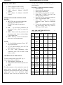
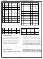
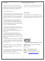
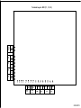
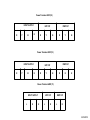
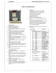
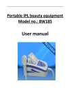
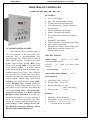
USER MANUAL PROTON POWER CONTROL PVT LTD PUNE INDUSTRIAL RO CONTROLLER TYPES ARO_33M / ARO_13M / ARO_11M FEATURES: AUTOMATION PHILOSOPHY: The Industrial RO Controller Panel is used for operation of the RO plants. The controller has a pre-programmed RO operating logic. The control panel can take 6 inputs signals, namely: Low Pressure Switch (LPS), High Pressure Switch (HPS), Raw Water Level Switch (RWL), Permeate Tank Level Switch (TWL), 2 Auxiliary Inputs (Used for interlocking with the automatic pretreatment Multi Port Valves). The controller also provides for a Conductivity input. Flow sensing is optional. The Control panel gives 4 control outputs, namely: Raw water Pump (RWP) on/off, High Pressure Pump (HPP) on/off, Flushing Valve Solenoid open/close (230VAC), Dosing Pump on/off (230VAC). Auto MPV power connection is available for Auto mode. Pump Time / Alarm selectable potential free contact is available. Manual Backwash Alert Indication (selectable for Manual Pretreatment) as an alert message is given. The advanced electronics also takes care of the required motor protection such as Over Voltage , Under Voltage, Over Load, Dry Running and Single Phasing / Phase Reversal with settable parameters. 16 x 2 LCD display. Easy User Programmable Settings. Set Parameter Password Protected. 4 Key Interface for Control and Onsite Programming. Process Status message Display. Alarm / Fault Message Display. Front Panel LED indications for active devices. Plant RUN time display. Total Cumulative Flow display (Optional). Auto / Manual Operation Pump Motor Voltage/Current display and Pump Motor Protection effective in Manual Mode as well. SPECIFICATIONS: Supply voltage : 230VAC ± 20%, 50Hz. (for single phase models) 415VAC ± 20% 50Hz. (for three phase models) Current range : 0-20 A. Current Resolution (Display) : 0.1 A Environmental : Operationg Temp : 0 to 55º C Storage Temp : 10 to 70º C Relative humidity :0 – 95% (Non-Condensing) Warm up time : 10 Sec Enclosure : 1 Mounting : Panel mounting. Dimensions : 225 (W) X 255 (H) X130 (D). Cutout Size : 192 (W) x 217 (H). (All dimensions are in mm.) USER MANUAL PROTON POWER CONTROL PVT LTD PUNE 6. Low Pressure (LP) I/P : It should be OPEN WORKING: on low (set on the Pressure Switch) pressure There are two mode of operation, and CLOSE on once the desired pressure is 1) Auto Mode. 2) Manual Mode. achieved. All the protections like Current Overload, Over / Under Voltage, Phase Current Unbalance are effective in Auto as well as manual mode. Auto/ Manual selection is done with the help of a front panel switch.. In either mode, in case of a fault, the relevant pump motor is tripped.. 7. Conductivity Input: It is an analog input AUTO MODE: Auto mode provides for Automatic Pre-treatment through Auto MPVs (the MPV mode) or with manual pretreatment, (the AUTO mode) . In MPV mode RWP operation is maintained while Auto pre-treatment is on. This is achieved by taking two discrete Auxiliary (AUX) inputs from the Auto MPVs (namely “pretreatment on” and the “RWP pump on/off”) following power outputs governed by from conductivity sensor. 8. Flow input (Optional): It is a pulse type input from Flow sensor. In Auto Mode the controller provides for various interlocks: 1. Raw Water Pump on/off 2. High Pressure Pump on/off 3. Flush valve Solenoid on/off 4. “PUMP ON” potential free feedback to Auto MPV in case of automatic pretreatment / “ALARM” potential free output In AUTO mode controller senses digital inputs after starting the pumps. The process is controlled based on the digital input responses. The digital inputs are as follows: on faul/tript condition (as selected in setting) 5. Dosing Pump Power Output. 1. Auxiliary I/P 1: Pre-Treatment On from Auto MPV. 6. Auto MPVs Power Output (Disabled in 2. Auxiliary I/P 2 : Pump On/Off signal from Various process states, values and faults are Manual Mode). indicated on the LCD display and panel LEDs. Auto MPV which tells the controller if the Pump needs to be off during Auto MPV MANUAL MODE: In this mode the control is achieved by operation of the Raw Water and High Pressure Pumps through two separate switches, one for each motor to turn it ON and OFF. In manual mode the motor operation is independent from digital inputs, however, the electrical protection is effective as mentioned above. transition between it’s Backwash / Rinse / Service Cycles. 3. Raw Water Tank Empty I/P (RWL) : Normally it’s contact should be OPEN. 4. Treated water Full Level I/P TWL) : Normally it’s contact should be CLOSED. 5. High Pressure (HP) I/P : Normally it’s All the LED indications are effective in Manual mode except the Flush valve. contact should be OPEN and Close on high pressure being sensed.. 2 USER MANUAL PROTON POWER CONTROL PVT LTD PUNE second then controller automatically goes to initial display. Procedure to change parameter settings: 1. Press SET key. 2. Select particular parameter. 3. Enter Correct Password. 4. Press ENT to get password accepted. 5. Using INC & DEC key user can change setting parameters. 6. Press INC Key to increment parameter value up to maximum limit. 7. Press DEC key to decrement parameter value down to minimum limit. 8. To save the settings (value) press ENT key, then press SET key, scroll to EXIT, press ENT again. FRONT SWITCHES: 1. Power supply ON/OFF switch. 2. Auto / Manual selection switch. 3. RWP (Motor1) Manual ON/OFF control. 4. HPP (Motor 2) Manual ON/OFF control. INTRSUCTION FOR SETTINGS THE PANEL: 1. SET : This key is used to change the controller from RUN mode to FUNCTION mode for parameter setting. 2. INC : Up scroll the parameters & parameter value. (Also to restart the system) 3. DEC : Down scroll the parameters & parameter value. (also to acknowledge Cond. High Alert) 4. ENT : This key is used to Select/Save & to move to next parameter. ARO PARAMETER SETTINGS: Select Password 10) Sr. No Parameter ( Defaul t Min Max Unit 1 Slow flush time 5 0 999 sec NOTE: To Load default parameter Press INC key on power ON. To view RUN-HOUR, press SET & INC both keys at a time. To view Total cumulative flow (optional) press SET & DEC both keys at a time. 2 Fast Flush time 10 0 999 sec 3 Auto Flush enable Yes Yes No - 4 Flush Interval 120 5 360 min 5 Cond/TDS Const 1 0.1 2.0 - OPERATION OF THE PANEL: 6 Conductiv ity high 200 10 2000 µS 7 Conductiv ity Very high 200 10 2000 µS 8* Flow Constant 100 1 1000 ml/p ulse 9* Flow Low 0 1 1000 m3/h r 10* Flow Very Low 0 1 1000 m3/h r 11 LP trip delay 50 0 300 Sec To enter settings mode press SET key, it shows three menus as follows: RO Parameter. [Password 10] Pump Electrical Parameter. [Password 9995] Exit. To edit parameter select particular menu & enter correct password with the help of INC/DEC keys then pres ENT key, to change value and view next parameter press INC/DEC keys. If no key is pressed for five 3 USER MANUAL 12 PreTreatment Mode PROTON POWER CONTROL PVT LTD PUNE Manual Manual AMPV 13 * Reset flow counter No 14 RW Float Bypass No No Yes 15 TW Float Bypass No No Yes 16 Cond./TD S Bypass No No Yes Yes No 3 OL Trip Delay 5 1 30 4 HPP Underload 0.0 0.0 10.0 5 RWP Underload 0.0 0.0 10.0 6 UL trip delay 1 30 5 Ssec 7 OV Set Pt 260 100 500 V 9 UV Set Pt 0 400 V 10 SPP/RP Bypass Yes Yes No 11 Voltage + Offset 0 0 100 V 0 0 100 V 40 20 100 Percnt 40 20 100 Percnt 1 30 5 Sec - - BW Alert Bypass Yes 18 Select Cond/TDS Cond. Cond. TDS 19 Set MAN BW Time 24 24 Hr. 13 20 Aux. Output Pump Time Pump Time Alarm 14 17 No Yes 12 *optional 15 Voltage Offset HPP Unbalance Current RPW unbalance current UB Trip Delay Sec PUMP ELECTRICAL PARAMETER SETTINGS: (Password is 9995) MAXIMUM RECOMMENDED HP RATING: Sr. No Parameter Default Min Max Unit 1 HPP Over Load 5.0 2.0 20.0 Amp 2 RWP over load 5.0 2.0 20.0 Amp Panel Configuration ARO_11M ARO_13M ARO_33M Raw Water Pump High Pressure Pump 2HP Single Phase 2HP Single Phase 2HP Single Phase 7.5 HP three Phase 5 HP three Phase 7.5 HP three Phase Automation Philosophy: The Industrial RO control panel provides for very convenient mounting and easy field cable terminations. Removable terminals blocks are provided for easy terminations. Different sizes of terminals are selected for process and power connections to avoid wrong connections. The industrial RO control panel is based on state of the art technology processor. It has 6 digital inputs and four outputs. It also has Conductivity and Flow (pulse type) Sensor inputs. It can be set for Manual pre-treatment operation or Automatic pre-treatment operation. 4 On powering the controller it checks for Raw Water Tank (RWT) level and the Treated Water Tank (TWT) level. On receiving signals that the RWT is not empty and TWT is not full, it starts up the Raw water Pump (RWP). A Low Pressure Switch (LPS) check the pressure developed at the suction of HPP. On receiving the signal that pressure is developed (LPS) at the suction of High Pressure Pump (HPP), it opens the Flush (reject) Solenoid valve for a settable time, ensuring slow flush. After this, the HPP is started for a settable time ensuring fast flush. At the end of this time Flush Solenoid valve is closed and RO is started/operational. The controller continuously checks the pressure (LPS) at the HPP suction. Should it fall, a message is displayed with an LED indication USER MANUAL PROTON POWER CONTROL PVT LTD PUNE on the front panel. After a settable delay if this condition prevails, the RO is shut with a message on the LCD screen. The system can be restarted only with activation of the Start key or Power reset. Conductivity value, Voltage, Pump Current and various states are displayed on the LCD screen. If during RO in operation: Manual Mode: - RWT empty signal is received, both the pumps stop immediately with a message on the LCD, and an LED - RWP and HPP can be started through front panel indication for RWP level. RO restarts automatically keys. HPP is interlocked with RWP in this mode. The on receiving Raw water tank low level signal goes pump motor protection is active in this as well. off. - TWT full signal is received, a flush sequence is carried out and then both the pumps stop with a message on the LCD screen and an LED indication. Once TWT full signal goes off, Slow and Fast flush sequence is initiated and RO starts. - High Pressure switch (HPS) activation is received, both the pumps stop immediately with a message on the LCD, and an LED indication for HPS. RO can be restarted on activating Start key or Power reset. - Conductivity value exceeds set High level, a message is displayed till the time value is between High and Very High Limits set. Pressing ENT key the display scrolls again and checks for the Cond. Value for 3 mins. If the Conductivity value exceeds the Very High limit set, both the pumps stop immediately with a message on the LCD. RO can be restarted on activating Start key or Power reset. TM PROTON PROTON POWER CONTROL PVT. LTD. Office & Work : S.NO.28 JAGTAP DAIRY, PIMPLE NILAKH If Auto Multi Port valves are used, it’s Backwash Sequence is co-ordinated by connecting AUX1 and AUX2 inputs of ARO. PUNE-411027 Phone : 020-27270800, 27276777 Mobile : 9764885010/9422009655. E-mail : [email protected] - Any electrical faults at RWP and / or HPP such as Overload, Dry Run, Over Voltage, Under Voltage the RO stops after the set trip values and delays, with relevant fault display on the LCD. Website : www.protonelectronic.com 5 T1 T2 2 C 7 NO 8 C C NO NO 6 9 NO LP I/P HP I/P 5 10 TWL I/P 4 RWE I/P 3 C 1 CONDUCTIVITY Terminal Layout ARO (11 , 13, 33) 11 12 13 14 15 16 17 18 19 20 C NO C NO C NO AUX1 I/P AUX2 I/P PUMP TIME 21 L MPV O/P 22 23 N C 24 25 26 NO L N FLUSHING O/P DOSING O/P 23/02/2015 Power Terminal ARO (33) INPUT SUPPLY R Y N B RWP O/P HPP O/P R Y B R Y B Power Terminal ARO (13) INPUT SUPPLY R Y N B RWP O/P HPP O/P R Y B R N E Power Terminal ARO (11) INPUT SUPPLY L N HPP O/P E L N RWP O/P L N 23/02/2015