1
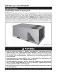
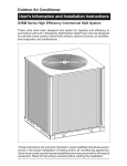
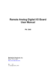
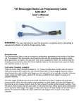
XB Starter Kit
XB Starter Kit
is an RF communication module based
on XBee®. This module uses the IEEE 802.15.4 standard
operating at a frequency of 2.4 GHz.
Several parameter settings can be done via X-CTU
program. This module can be used in wireless data
transaction applications such as warehouse inventory
system, indoor sensors reading, etc.
Specification
1. Based on XBee® OEM RF Module.
2. Configurable 1 input pin and 8 input/output pins (7
of which can also be used as analog inputs).
3. Configurable 2 PWM output pins.
4. UART TTL or RS-232 communication lines are
available.
5. Reset switch and indicator LED are available.
6. Requires 5 Volt DC power supply input.
Pin
1&6
2
Name
GND
V33
3
PWM0
4
PWM1
5
SLP_RQ
Function
Ground reference
3.3V power supply output
Can be used as a signal strength
indicator or PWM for ADC0
Can be used as PWM for ADC1
Can be used as a sleep or DI8
(input) control pin
Important!
•
To perform firmware update, SLP_RQ/DI8 must be
connected to GND.
Header I/O PORT (J8) contains 8 input/output lines.
I/O PORT (J8) Pin Allocation
1
GND
IO0
IO2
IO4
IO6
Component Layout
Pin
1
2
3 s/d 10
V33
IO1
IO3
IO5
IO7
Name
GND
V33
IO0 - IO7
Function
Ground reference
3.3V power supply output
DIO0 – DIO7 input/output pin
Important!
•
All input/output pins (except for IO5 and IO7) has an
optional internal pull up resistor which can be set via
configuration setting.
IO5 selection as association indicator or as I/O can be set
via jumper J6.
Function
J6
Position
Tactile switch RESET (S1) is used to reset the module.
LED POWER (D2) is the power supply indicator.
LED ON/SLEEP (D3) is the module condition indicator.
LED ASSC (D4) is an association indicator which will blink
according to the module function and the communication
line condition (If IO5 is configured as association
indicator).
J2 Blue Terminal serves as power supply input lines.
PWM/PROG (J5) header contains PWM and input line.
PWM/PROG (J5) Pin Allocation
V33
PWM1
GND
Association Indicator
J6
J6
1
2
3
ASSC
1
2
3
ASSC
Important!
•
If IO5 is configured as I/O line then jumper J6 must
be at position 1-2 and pin will be connected to the
I/O PORT (J8).
•
If IO5 is configured as association indicator, then
jumper J6 must be on position 2-3 and pin will be
connected to LED ASSC (D4). Pin will also be
connected to ASCT (UART INT J7) through a voltage
level converter.
UART mode selection (TTL or RS-232) can be configured
via J3 and J4.
UART
1
GND
PWM0
SLP_RQ
I/O
TTL
RS-232
J4 J3
J4 J3
1
2
3
J3 & J4
Positions
TX RX
1
2
3
TX RX
UART INT (J7) Header contains UART TTL line and
association indicator.
UART INT (J7) Pin Allocation
1
GND
TXT
ASCT
Pin
1
2
3
4
Name
GND
VCC
TXT
RXT
5
ASCT
VCC
RXT
Function
Ground reference
5V power supply input
UART TTL data output line
UART TTL data input line
Association indicator which will
produce pulses according to the
module
function
and
the
communication line condition (If IO5 is
configured as association indicator).
Important!
•
VCC is also connected to J2 blue terminal. Pay
attention to the connections, especially if the module is
connected to Innovative Electronics microcontroller
products.
RJ11 RS232 (J1) is a connector for UART RS-232
communication line.
Name
Function
GND
Ground reference
TX
UART RS-232 data input
line
RX
UART RS-232 data output
line
6.
7.
8.
9.
10.
11.
Select Modem Configuration tab.
Select COM port in the bottom right status bar.
Press Load.
Select default.pro file.
Press Write.
Press Read on the X-CTU. If it's successful then the
configuration will be displayed. If this fails, the
notification window will appear. Make sure the results
are:
1. Modem
: XB24
2. Function Set : XBEE 802.15.4
3. Version
: 10EC
Version number depends on the current firmware.
12. The D2 Power and D3 ON/SLEEP LEDs should light up
continuously. The ASSC D4 LED and LED on bit 2 LED
Logic Tester will blink (LED Logic Tester will blink
opposite of ASSC D4 LED).
Two Modules Testing Procedure
1. Connect jumper J3 and J4 on position 2-3 and J6 on
position 1-2. Release LED Logic Tester.
2. Connect both modules (or one of the modules that will
be tested) to PC COM Port.
3. Power on both modules.
4. Run X-CTU to program default jual.pro.
5. Run XBeeTester.exe for testing. Select COM Port that
is connected to module A and press Open.
6. Wait about 2 seconds then the display will change as
shown below:
J1 Front side look
5 4 3 2
RX GND
TX
CD/DVD Contents
1. XCTU© software, how to use, and profile.
2. Program XBeeTester.exe for testing.
3. Datasheet.
4. XB Starter Kit Manual.
5. XB Starter Kit Schematic.
6. Application examples.
7. Innovative Electronics Website.
X-CTU Installation and Update
1. Run XCTU setup.exe and follow the next instructions.
2. After installation is completed, run X-CTU, choose
Modem Configuration tab, click Download new
versions... button, and then click File...button.
3. Point to update folder in CD/DVD and choose
xb24_15_4_10ec.zip.
One Module Testing Procedure
1. Connect jumper J3, J4, and J6 on position 2-3.
2. Connect UART INT (J7) header to LED Logic Tester.
3. Connect module with the PC via a serial cable to J1
RJ11 connector.
4. Connect J2 blue terminal to 5V power supply.
5. Run X-CTU for programming.
Make sure the statuses lit with blue color are AD1,
AD0, DI8, DI7, DI6, DI5, DI4, DI3, and DI2.
7. On module B, connect pin IO0 and IO1 alternately to
GND and V33 (header I/O PORT J8). Examine
PWM0 and PWM1 (pin 3 and 4 header
PWM/PROG J5) module A using a voltmeter. The pin
connected to GND will produce 0 ADC value and 0V
PWM, while the pin connected to V33 will produce
ADC 3FF and PWM about 3.3V.
8. On module B, connect pin IO2, IO3, IO4, IO5, IO6
and IO7 (I/O PORT J8 header) and SLP_RQ
(PWM/PROG J5 header) alternately to GND. If it's
successful then XBeeTester's DI2, DI3, DI4, DI5, DI6,
DI7, and DI8 will turn off according to the pin
connected to GND.
9. On module B, connect pin IO5 and IO7 (header I/O
PORT J8) alternately to V33. If it's successful then
XBeeTester DI5 and DI7 will lit green according to the
pin connected to V33.
Trademarks & Copyright
XBee is a registered trademark of Digi International, Inc.
XCTU is copyright by Digi International, Inc.
♦
Thank you for your confidence in using our products, if there
are difficulties, questions, or suggestions regarding this
product please contact our technical support:
[email protected]