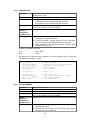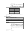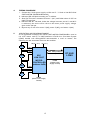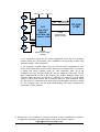
1
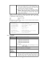
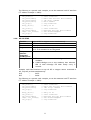
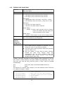
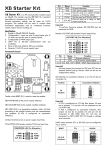
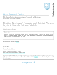
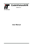
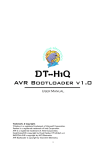
Smart Peripheral Controller Low Cost Motor Controller Trademarks & Copyright AT, IBM, and PC are trademarks of International Business Machines Corp. Pentium is a registered trademark of Intel Corporation. Windows is a registered trademark of Microsoft Corporation. CodeVisionAVR is copyright by Pavel Haiduc, HP InfoTech s.r.l. Table Of Contents 1 Introduction............................................................................................... 1.1 SPC LOW COST MOTOR CONTROLLER Specification..................... 1.2 Suggested System...................................................................................... 3 3 3 2 SPC LOW COST MOTOR CONTROLLER Hardware................................... 2.1 SPC LOW COST MOTOR CONTROLLER Component Layout........... 2.2 Connectors and Jumpers Configurations............................................... 4 4 4 3 SPC LOW COST MOTOR CONTROLLER Interface..................................... 3.1 UART TTL Interface..................................................................................... 3.2 I2C Interface................................................................................................ 3.3 Command Set.............................................................................................. 3.3.1 DC Forward................................................................................................. 3.3.2 DC Reverse.................................................................................................. 3.3.3 DC Stop........................................................................................................ 3.3.4 DC All Stop.................................................................................................. 3.3.5 Stepper Continuous Run............................................................................ 3.3.6 Stepper Pulse Count Run........................................................................... 3.3.7 Stepper Brake............................................................................................ 3.3.8 Stepper Stop............................................................................................... 3.3.9 Set I2C Address........................................................................................... 3.3.10 Read I2C Address....................................................................................... 6 6 7 8 8 9 10 11 12 13 14 15 15 16 4 Testing Procedure..................................................................................... 17 5 Application and Program Example.......................................................... 17 Attachment A. SPC LOW COST MOTOR CONTROLLER Schematics......................... 2 19 1. INTRODUCTION Smart Peripheral Controller / SPC LOW COST MOTOR CONTROLLER is a DC and stepper motor controller module which is compact, reliable, and compatible for robotic applications. This module can be used to control the direction and speed of 4 DC motors using the Pulse Width Modulation (PWM) method or 2 stepper motors using full-step or half-step. This module is equipped with quad full H-Bridge driver, UART TTL interface, and I2C interface, so that it can easily be connected with other systems. 1.1. SPC LOW COST MOTOR CONTROLLER SPECIFICATION SPC LOW COST MOTOR CONTROLLER specification is as follows: • The module requires 4.8 – 5.4 VDC power supply. • The motor requires 8 – 36 VDC power supply. • Uses a A3988 motor driver IC. • Each driver's maximum continuous current is 1.2 A. • Can be used for unipolar or bipolar stepper motors. • Input/Output pins are compatible with TTL and CMOS voltage level. • Equipped with UART TTL and I2C interface. • Using I2C, SPC LOW COST MOTOR CONTROLLER can be cascaded up to 8 modules. 1.2. SUGGESTED SYSTEM Suggested system for SPC LOW COST MOTOR CONTROLLER is as follows: Hardware: • PC™ AT™ Pentium® IBM™ Compatible with USB port. • DT-AVR Low Cost Series. • DVD-ROM Drive and Hard disk. Software: • Windows® XP Operating System. • CodeVisionAVR©. • Program CD/DVD contents: Contoh_i2c folder, contoh_uart folder, A3988.pdf, and SPC Low Cost Motor Controller Manual.pdf. 3 2. SPC LOW COST MOTOR CONTROLLER HARDWARE 2.1. SPC LOW COST MOTOR CONTROLLER COMPONENT LAYOUT 2.2. CONNECTORS AND JUMPERS CONFIGURATIONS INTERFACE PORT (J1) connector functions as a connector for module power supply input, motor power supply input, UART TTL interface, I2C interface, and motors. Pin Name Function st 1 M11 1 Output from H-Bridge M1 pair 2 M12 2nd Output from H-Bridge M1 pair 3 M21 1st Output from H-Bridge M2 pair 4 M22 2nd Output from H-Bridge M2 pair 5 M31 1st Output from H-Bridge M1 pair 6 M32 2nd Output from H-Bridge M3 pair 7 M41 1st Output from H-Bridge M1 pair 8 M42 2nd Output from H-Bridge M4 pair 9 MGND 10 VM Connected to motor power supply (8 – 36 Volts) 11 SCL I2C-bus clock input 12 SDA I2C-bus data input / output 13 RXD TTL serial level input to SPC module 14 TXD TTL serial level output from SPC module 15 PGND 16 VIN Ground reference for motor power supply Ground reference for SPC module power supply Connected to power supply (4.8 – 5.4 Volts) 4 J3, J4, J6, and J7 jumpers are used to select operation mode for each HBridge on the SPC module. M1 & M2 Functions J3 & J4 Position DC Motor Controller 1 2 3 M3 & M4 Functions J6 & J7 Position DC Motor Controller 1 2 3 J3 J4 Stepper Motor Controller J6 J7 1 2 3 1 2 3 Stepper Motor Controller J3 J4 J6 J7 Pay attention to the type of stepper motor connected to SPC LOW COST MOTOR CONTROLLER because each type has its own connection. SPC LOW COST MOTOR CONTROLLER can be utilized for 3 types of stepper motor: Bipolar, 5 cables Unipolar, and 6 cables Unipolar. The following are the connection examples for each stepper motor type: Bipolar Konektor J1 8V-36V M VM A M11/M31 M12/M32 B M21/M41 M22/M42 C MGND D Ground Catu Daya Motor Unipolar 5 kabel Konektor J1 M A 8V-36V VM B M11/M31 M12/M32 C D COMMON 5 M21/M41 M22M42 MGND Ground Catu Daya Motor Unipolar 6 kabel Konektor J1 8V-36V VM A M M11/M31 M12/M32 B M21/M41 M22/M42 C MGND D Ground Catu Daya Motor COMMON 1 COMMON 2 SCL-SDA (J5) jumpers are used to activate pull-up resistors for SDA and SCL on I2C interface. Jumper SCL-SDA J5 Function Pull-up inactive (jumpers disconnected) SCL SDA Pull up active (jumpers connected) SCL SDA Important! If more than one module is connected to I2C-bus, then only one set of SCLSDA (J5) jumpers needs to be connected. I2C address configuration can be done through UART TTL interface. M1 IND (D3), M2 IND (D4), M3 IND (D5), and M4 IND (D6) LEDs function as motor condition indicator. 3. SPC LOW COST MOTOR CONTROLLER INTERFACE SPC LOW COST MOTOR CONTROLLER has UART TTL and I2C interfaces that can be used to receive commands or send data. 3.1. UART TTL INTERFACE UART TTL communication parameters are as follows: • 38400 bps • no parity bit • 8 data bits • no flow control • 1 stop bit 6 All commands sent through UART TTL interface begin with 1 byte data that contains <command number>, followed by (if needed) n-byte data command parameter. If the command and parameters transmission succeeded, then SPC LOW COST MOTOR CONTROLLER will send 0x06 (Acknowledged/ACK). If the command is not recognized, the SPC LOW COST MOTOR CONTROLLER will send 0x15 (Not Acknowledged/NCK). If the command is recognized but the command parameter is incorrect, then SPC LOW COST MOTOR CONTROLLER will not send any feedback. If the command sent is a command requesting data from SPC LOW COST MOTOR CONTROLLER module, then SPC LOW COST MOTOR CONTROLLER will send the data via TX TTL line. A data parameter that has a range larger than 255 decimals (larger than 1 byte) will be sent in two steps. 1 byte MSB data is sent first and is followed by LSB data. For example: parameter <pulse delay> which has a range of 1 65535. If <pulse delay> has a value of 1500 then MSB byte will be 5 and LSB byte will be 220 ((5x256)+220=1500). Available commands and parameters can be seen in section 3.3. 3.2. I2C INTERFACE SPC LOW COST MOTOR CONTROLLER module has an I2C interface. In this interface, SPC LOW COST MOTOR CONTROLLER module acts as a slave with an address that as been determined via UART command (see section 3.3.9). I2C interface on SPC LOW COST MOTOR CONTROLLER module supports bit rate up to a maximum rate of 50 kHz. All commands sent through I2C interface begin with start condition, followed by 1 byte of SPC LOW COST MOTOR CONTROLLER module address. After the address is sent, the master must send 1 byte data that contains <command number>, followed by (if needed) n-byte command parameter data. After all command parameters have been sent, the command is ended with stop condition. The following is the sequence that must be done to send a command via I 2C interface. Start + 1 1 1 0 X X X 0 + X X X Write Address X X X X X X X X + Command X X X X X + Parameter (if available) Stop If the command and parameters transmission succeeded, then SPC LOW COST MOTOR CONTROLLER will write a hexadecimal response 0x06 (Acknowledged/ACK) in its I2C buffer. But if the command is not recognized or the command parameter is incorrect then the SPC LOW COST MOTOR 7 CONTROLLER will write a hexadecimal Acknowledged/NCK) on its I2C buffer. response of 0x15 (Not Master can send a read command to read the <ACK/NCK> response. If the command sent is a command that requests data from SPC LOW COST MOTOR CONTROLLER module, then those data can be read after reading the response by using the read data command. The following is the sequence that must be done to read response and/or data from SPC LOW COST MOTOR CONTROLLER. Start 1 + 1 1 0 X X X 1 + X X X Read Address 0 0 0 X 0 1 X X + ACK / NCK ... + X X X X X X X X X + Data 1 (if available) X X X X + Stop Data n (jika ada) A data parameter that has a range larger than 255 decimals (larger than 1 byte) will be sent in two steps. 1 byte MSB data is sent first and is followed by LSB data. For example: parameter <pulse delay> which has a range of 1 65535. If <pulse delay> has a value of 1500 then MSB byte will be 5 and LSB byte will be 220 ((5x256)+220=1500). 3.3. COMMAND SET The following is a complete list of commands in UART and I2C interface: 3.3.1. DC FORWARD Function Command Parameter Response Delay between Command and Response Description Controls DC motor forward rotation 0x30 <Motor number> 1 DC motor connected to M1 2 DC motor connected to M2 3 DC motor connected to M3 4 DC motor connected to M4 <pwm level> 0 - 255 assigned duty cycle percentage (0 = 0%; 255 = 100%) 0x06 if command is recognized 0x15 if command is not recognized 10 µs ● Indicator LED light intensity for each H-Bridge (M1, M2, M3, and M4) will match the PWM value given. If the PWM value is 0 then the indicator LED will turn off. When the PWM value is 255 then indicator LED will light up with the highest intensity. 8 ● ● ● On forward condition, indicator LED will also blink. On forward condition, Mn1 (n is the H-Bridge number) will produce voltage proportional to the PWM value while Mn2 will be connected with MGND. Motor direction and PWM value will not be saved in EEPROM. When the SPC module is powered on, PWM values of each H-bridge is 0 (zero) and the motor will be in a stop condition (all-4 indicator LEDs will blink faintly every 2 seconds). Example with UART interface to control the forward speed of DC motor connected to M1. If the desired duty cycle is 50% (0.5 * 255 = 128) or equal to 128 decimal or 0x80 hexadecimal: User SPC : : 0x30 0x01 0x80 0x06 The following is a pseudo code example, to use this command with I2C interface (I2C address example = 0xE0): i2c_start(); i2c_write(0xE0); i2c_write(0x30); i2c_write(0x01); i2c_write(0x80); i2c_stop(); // // // // // // Start Condition Write SPC Low Cost Motor module “DC Forward” command Motor number PWM value Stop Condition delay_us(10); // delay 10 us i2c_start(); i2c_write(0xE1); temp = i2c_read(0); i2c_stop(); // // // // Start Condition Read SPC Low Cost Motor module Data Acknowledgment Stop Condition 3.3.2. DC REVERSE Function Command Parameter Response Delay between Command and Response Description Controls DC motor reverse rotation 0x31 <Motor number> 1 DC motor connected to M1 2 DC motor connected to M2 3 DC motor connected to M3 4 DC motor connected to M4 <pwm level> 0 - 255 assigned duty cycle percentage (0 = 0%; 255 = 100%) 0x06 if command is recognized 0x15 if command is not recognized 10 µs ● Indicator LED light intensity for each H-Bridge (M1, M2, M3, and M4) will match the PWM value given. If the PWM value is 0 then the indicator LED will turn off. When the PWM value is 255 then indicator LED will 9 ● ● light up with the highest intensity. On reverse condition, Mn2 (n is the H-Bridge number) will produce voltage proportional to the PWM value while Mn2 will be connected with MGND. Motor direction and PWM value will not be saved in EEPROM. When the SPC module is powered on, PWM values of each H-bridge is 0 (zero) and the motor will be in a stop condition (all-4 indicator LED will blink faintly every 2 seconds). Example with UART interface to control the reverse speed of DC motor connected to M1. If the desired duty cycle is 20% (0.25 * 255 = 64) or equal to 64 decimal and 0x40 hexadecimal: User SPC : : 0x31 0x01 0x40 0x06 The following is a pseudo code example, to use this command with I2C interface (I2C address example = 0xE0): i2c_start(); i2c_write(0xE0); i2c_write(0x31); i2c_write(0x01); i2c_write(0x40); i2c_stop(); // // // // // // Start Condition Write SPC Low Cost Motor module “DC Reverse” command Motor number PWM value Stop Condition delay_us(10); // delay 10 us i2c_start(); i2c_write(0xE1); temp = i2c_read(0); i2c_stop(); // // // // Start Condition Read SPC Low Cost Motor module Data Acknowledgment Stop Condition 3.3.3. DC STOP Function Command Parameter Response Delay between Command and Response Description Stops DC motor 0x32 <Motor number> 1 DC motor connected to M1 2 DC motor connected to M2 3 DC motor connected to M3 4 DC motor connected to M4 0x06 if command is recognized 0x15 if command is not recognized 10 µs ● On stop condition, Mn1 and Mn2 will be in a three state / high impedance condition. Example with UART interface to stop DC motor connected to M1: User SPC : : 0x32 0x01 0x06 10 The following is a pseudo code example, to use this command with I2C interface (I2C address example = 0xE0): i2c_start(); i2c_write(0xE0); i2c_write(0x32); i2c_write(0x01); i2c_stop(); // // // // // Start Condition Write SPC Low Cost Motor module “DC Stop” command Motor number Stop Condition delay_us(10); // delay 10 us i2c_start(); i2c_write(0xE1); temp = i2c_read(0); i2c_stop(); // // // // Start Condition Read SPC Low Cost Motor module Data Acknowledgment Stop Condition 3.3.4. DC ALL STOP Function Command Parameter Response Delay between Command and Response Description Stops all DC or stepper motors simultaneously 0x33 0x06 if command is recognized 0x15 if command is not recognized 10 µs ● ● This command will cause all H-bridges to be in a stop condition. If All H-Bridges are in stop condition, then indicator LED of each H-Bridge will blink faintly every 2 seconds. Example with UART interface to stop all DC or stepper motors connected to M1, M2, M3, and M4 simultaneously: User SPC : : 0x33 0x06 The following is a pseudo code example, to use this command with I2C interface (I2C address example = 0xE0): i2c_start(); i2c_write(0xE0); i2c_write(0x33); i2c_stop(); // // // // Start Condition Write SPC Low Cost Motor module “All Stop” command Stop Condition delay_us(10); // delay 10 us i2c_start(); i2c_write(0xE1); temp = i2c_read(0); i2c_stop(); // // // // Start Condition Read SPC Low Cost Motor module Data Acknowledgment Stop Condition 11 3.3.5. STEPPER CONTINUOUS RUN Function Command Parameter Controls stepper motor so that it rotates continuously 0x34 <Motor number> 1 stepper motor connected to M1 and M2 2 stepper motor connected to M3 and M4 <step type> 1 Full-Step: motor will rotate 1 step every 1 pulse 2 Half-Step: motor will rotate ½ step every 1 pulse <direction> 0 motor will rotate clockwise 1 motor will rotate counter clockwise Response Delay between Command and Response Description <pulse delay> 1 - 65535 Delay time between pulse to stepper motor. The smaller the pulse delay, the faster the stepper motor rotates 0x06 if command is recognized 0x15 if command is not recognized 10 µs ● ● If the stepper motor rotates to an opposite direction, then it means that the connection is reversed. To fix it, change the order of connection installation. One pulse delay value represents delay time between pulse for about 1 ms. Example with UART interface to run the stepper motor connected to M1 and M2 so that it rotates clockwise continuously, with a full-step step type, and the delay between pulse is about 100 ms (0x0064 hexadecimal): User SPC : : 0x34 0x01 0x01 0x00 0x00 0x64 0x06 The following is a pseudo code example, to use this command with I2C interface (I2C address example = 0xE0): i2c_start(); i2c_write(0xE0); i2c_write(0x34); i2c_write(0x01); i2c_write(0x01); i2c_write(0x00); i2c_write(0x00); i2c_write(0x64); i2c_stop(); // // // // // // // // // Start Condition Write SPC Low Cost Motor module “Stepper Continuous Run” command Motor number Step type Direction MSB pulse delay LSB pulse delay Stop Condition delay_us(10); // delay 10 us i2c_start(); i2c_write(0xE1); temp = i2c_read(0); i2c_stop(); // // // // Start Condition Read SPC Low Cost Motor module Data Acknowledgment Stop Condition 12 3.3.6. STEPPER PULSE COUNT RUN Function Controls stepper motor so that it rotates according to how many steps given 0x35 <Motor number> 1 stepper motor connected to M1 and M2 2 stepper motor connected to M3 and M4 Command Parameter <step type> 1 Full-Step: motor will rotate 1 step every 1 pulse 2 Half-Step: motor will rotate ½ step every 1 pulse <direction> 0 motor will rotate clockwise 1 motor will rotate counter clockwise <pulse delay> 1 - 65535 Delay time between pulse to stepper motor. The smaller the pulse delay, the faster the stepper motor rotates Response Delay between Command and Response Description <pulse count> 1 - 65535 the number of pulse sent to stepper motor 0x06 if command is recognized 0x15 if command is not recognized 10 µs ● ● ● If the stepper motor rotates to an opposite direction, then it means that the connection is reversed. To fix it, change the order of connection installation. One pulse delay value represents delay time between pulse for about 1 ms. After the number of pulse that has been released matches the pulse count, stepper motor will automatically stop (on brake condition) while still maintaining motor torque (current is still flowing through stepper motor coils). Example with UART interface to run the stepper motor connected to M1 and M2 so that it rotates clockwise 20 pulses (0x0014 hexadecimal), with a fullstep step type, and the delay between pulses is about 1000 ms (0x03E8 hexadecimal): User SPC : : 0x35 0x01 0x01 0x00 0x03 0xE8 0x00 0x14 0x06 The following is a pseudo code example, to use this command with I2C interface (I2C address example = 0xE0): i2c_start(); i2c_write(0xE0); i2c_write(0x35); i2c_write(0x01); i2c_write(0x01); i2c_write(0x00); // // // // // // Start Condition Write SPC Low Cost Motor module “Stepper Pulse Count Run” command Motor number Step type Direction 13 i2c_write(0x03); i2c_write(0xE8); i2c_write(0x00); i2c_write(0x14); i2c_stop(); // // // // // MSB pulse delay LSB pulse delay MSB pulse count LSB pulse count Stop Condition delay_us(10); // delay 10 us i2c_start(); i2c_write(0xE1); temp = i2c_read(0); i2c_stop(); // // // // Start Condition Read SPC Low Cost Motor module Data Acknowledgment Stop Condition 3.3.7. STEPPER BRAKE Function Command Parameter Response Delay between Command and Response Description Stops the stepper motor while still maintaining motor torque (current is still flowing through stepper motor coils). 0x36 <Motor number> 1 stepper motor connected to M1 and M2 2 stepper motor connected to M3 and M4 0x06 if command is recognized 0x15 if command is not recognized 10 µs ● ● ● This command can be given after the Continuous Run command. On brake condition, stepper motor will stop while still maintaining motor torque (current is still flowing through stepper motor coils). On brake condition, indicator LED will lit up according to the last Run command. Example with UART interface to stop the stepper motor connected to M1 and M2: User SPC : : 0x36 0x01 0x06 The following is a pseudo code example, to use this command with I2C interface (I2C address example = 0xE0): i2c_start(); i2c_write(0xE0); i2c_write(0x36); i2c_write(0x01); i2c_stop(); // // // // // Start Condition Write SPC Low Cost Motor module “Stepper Brake” command Motor number Stop Condition delay_us(10); // delay 10 us i2c_start(); i2c_write(0xE1); temp = i2c_read(0); i2c_stop(); // // // // Start Condition Read SPC Low Cost Motor module Data Acknowledgment Stop Condition 14 3.3.8. STEPPER STOP Function Command Parameter Response Delay between Command and Response Description Stops the stepper motor (current doesn't flow through stepper motor coils) 0x37 <Motor number> 1 stepper motor connected to M1 and M2 2 stepper motor connected to M3 and M4 0x06 if command is recognized 0x15 if command is not recognized 10 µs ● ● ● This command can be given after Continuous Run, Pulse Count Run, or Brake command. On stop condition, stepper motor will stop and there will be no current flowing through the motor coils. Stop condition is the default condition when the SPC module is powered on Example with UART interface: User SPC : : 0x37 0x01 0x06 The following is a pseudo code example, to use this command with I2C interface (I2C address example = 0xE0): i2c_start(); i2c_write(0xE0); i2c_write(0x37); i2c_write(0x01); i2c_stop(); // // // // // Start Condition Write SPC Low Cost Motor module “Stepper Stop” command Motor number Stop Condition delay_us(10); // delay 10 us i2c_start(); i2c_write(0xE1); temp = i2c_read(0); i2c_stop(); // // // // Start Condition Read SPC Low Cost Motor module Data Acknowledgment Stop Condition 3.3.9. SET I2C ADDRESS Function Command Parameter Response Delay between Command and Response Description Changes I2C address 0x41 <0xAA> <0x55> <newAddress> 0x06 if command is recognized 0x15 if command is not recognized 10 µs ● ● This command can only be performed via UART communication line. SPC module will use the new I2C address after going through power off sequence. 15 ● ● ● ● The allowed I2C address <newAddress> can be seen in the table below. If the new address given is incorrect, then the I 2C address will not be changed (the previous address will be used). The default I2C address is 0xE0. I2C address data will be saved in EEPROM so it won't be erased when it's powered off. I2C Address I2C Write Address I2C Read Address 0xE0 0xE1 0xE2 0xE3 0xE4 0xE5 0xE6 0xE7 0xE8 0xE9 0xEA 0xEB 0xEC 0xED 0xEE 0xEF Example with UART interface to change the I2C address from 0xE0 to 0xE2: User SPC : : 0x41 0xAA 0x55 0xE2 0x06 3.3.10. READ I2C ADDRESS Function Command Parameter Response Delay between Command and Response Description Reads the current I2C address 0x42 <I2CAddress> if command is recognized 0x15 if command is not recognized 10 µs ● ● ● This command can only be performed via UART communication line. SPC module's I2C address can also be seen through the number of blinks on the indicator LED when the module is powered on. If the I2C address is 0xE0 then the indicator LED will blink once. If the I2C address is 0xE2 then the indicator LED will blink twice. If the I2C address is 0xE4 then the indicator LED will blink 3 times, and so on until I 2C address 0xEE at which the indicator LED will blink 8 times. Example with UART interface: User SPC Module : : 0x42 <I2CAddress> 16 4. TESTING PROCEDURE 1. Connect the 5 Volts power supply to VIN and 9 - 12 Volts to VM SPC LOW COST MOTOR CONTROLLER module. 2. Indicator LED will blink according to I2C address. 3. Send “DC Forward” command to motor 1 (M1) with PWM value of 255 via UART TTL interface. 4. Indicator LED M1 will blink. When the voltage between pin M11 and M12 is measured, the result will be close to the motor power supply voltage given on the VM pin. 5. Repeat step 3 and 4 for motor 2 (M2), motor 3 (M3), and motor 4 (M4). 5. APPLICATION AND PROGRAM EXAMPLE As an application example, SPC LOW COST MOTOR CONTROLLER is used to run 4 DC motors with I2C or UART interface. DT-AVR Low Cost Micro System (LCMS) module with ATmega8535 microcontroller is used as master. The following are the connections between the modules: VM (8V – 36V ) M1 VIN (+5 V ) M11 M12 SDA SDA (PORTD.2) M21 M22 M2 M3 SCL SCL (PORTD.3) SPC LOW COST MOTOR CONTROLLER (address 0xE0) M31 M32 M41 M42 M4 MGND (Motor Power Supply Ground) 17 PGND (Digital Power Supply Ground) DT-AVR LCMS VM (8V – 36V ) M1 VIN (+5 V ) M11 M12 M21 M22 M2 M3 SPC LOW COST MOTOR CONTROLLER (address 0xE0) TXD RX (PORTD.0) RXD TX (PORTD.1) DT-AVR LCMS PGND (Digital Power Supply Ground) M31 M32 M41 M42 M4 MGND (Motor Power Supply Ground) As an example program for the above application, there are two programs named contoh_i2c.c and contoh_uart.c (included in the CD/DVD) written using CodeVisionAVR 1.25.2 evaluation. In the program, DT-AVR LCMS will send "DC Forward" command for each motors with PWM value of 255 to SPC module (for example, SPC's I2C address is 0xE0) with about 1000ms delay for each command. After all of the commands are sent, DT-AVR LCMS will wait for 3000 ms. Afterward "DC All Stop" command will be sent to SPC followed by another 3000 ms delay. Then DT-AVR LCMS will send "DC Reverse" command for each motor with PWM value of 128 to SPC module with a 1000 ms delay for each command. When all "DC Reverse" commands have been sent, DT-AVR LCMS will wait for 3000 ms. The program ends with DT-AVR LCMS sending "DC Stop" command for each motor to SPC module. ♦ Thank you for your confidence in using our products, if there are difficulties, questions, or suggestions regarding this product please contact our technical support: [email protected] 18 ATTACHMENT A. SPC LOW COST MOTOR CONTROLLER Schematics 19