1
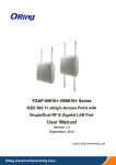
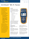
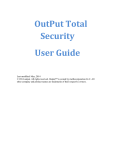
User Manual
Repeatit SU
Revision 3.1
Page 2(17)
Safety Precautions
This equipment must be installed in compliance with local and national building codes
and regulatory restrictions.
WARNING: To avoid possible injury or damage to equipment, you must use power
supply equipment that is safety certified according to UL, CSA, IEC, or other applicable
national or international safety requirements for the country of use. All references to
power supply in this document refer to equipment meeting these requirements.
WARNING: If the equipment is installed with an external antenna a surge protection
device must be installed on the antenna connector of the equipment. The surge protection
must fulfil EN 60950-1 section 7 and insulation requirements between SELV and TNV
circuits in EN 60950-1.
How to Read the manual
All pictures in the manual are for illustration only, details can be changed wothout any
prior notice.
1. Installation
The Repeatit Subscriber Unit (SU) should always be mounted on the highest possible place with clear line
of sight to the base station (or Access Point). Usually, this means that you should mount the SU on the top
of your roof or at the TV antenna pole.
Page 3(17)
Mounted on Wall
Mounted on Pole
Note: Pictures are only for illustration, details can be changed without notice.
General information
When connecting/disconnecting the SU to a computer, it is important to follow the instructions in this
document.
System Requirements
•
•
One available Ethernet port
Browser (for example Internet Explorer or Mozilla)
Items included in the box
•
•
•
•
•
One Subscriber Unit.
One 48V Power over Ethernet (PoE) adaptor
One Ethernet cable.
One outdoor antenna holder. (Only outdoor units)
Quick install guide
Hardware installation of the Subscriber Unit
Outdoor units:
Page 4(17)
Connect the PoE adaptor to a power socket. The SU is connected to the PoE adaptor’s P+Data out socket
through the straight Ethernet cable that comes with the SU. The PC shall then be connected to the Data in
socket on the PoE adaptor via the Ethernet cable that is provided in the box.
Unit shall be grounded by connecting mounting bracket to proper earth grounding
Indoor units:
Connect the power supply to the unit and connect the PC cable to any of the two RJ45 sockets.
Computer settings
The client computer needs a network card that is properly installed. The network card normally use DHCP
configuration, which means that an IP address automatically is assigned when the computer is connected to
the SU.
Client terminal settings
When the SU is delivered, its IP address is set to 192.168.50.1. The built in DHCP server delivers IPaddresses in the range 192.168.50.2-100.
User interface
The subscriber unit is configured in a browser window. Start your browser and type the following line in
the address field:
http://192.168.50.1
Press Enter. A login window is shown. The default login settings are:
User name: admin
User name: user
Password: public
Password: public
Type the user name and the password in the fields provided and press OK. In the browser window, all
relevant SU settings can be monitored.
The WEB interface has 8 different tabs, the default tab that is shown is the status tab. To switch tab left
click with the mouse over the desired tab.
The two different usernames gives access to different levels of configuration:
Function
Admin
User
Status
X
X
Basic
X
Security
X
Network
X
X
VirtualServer
X
X
QoS
X
Admin
X
Maintenance
X
X
Tools
X
General wireless Installation
This guide can be used if the following two conditions hold:
Page 5(17)
•
•
The wireless network you want to connect to has a DHCP server (it gives you an IP address
automatically).
No wireless encryption is used.
How to connect to a network:
1.
2.
3.
4.
Ensure that the correct frequency range is chosen.
Press the Site Survey button in the Basic tab and wait 20-30 seconds until the scan is performed.
The network that your service provider has set up should be visible in the Site Survey window. Left
Click on the SSID of the network that you want to connect to. It will automatically be filled in the
SSID field under Radio Settings.
Press the Apply button.
When the signal strength is optimized, click the Refresh button in the lower, right corner of the screen until
your SU has received an IP address from the network. When this is done, the connection is established and
the connection is configured.
Received signal strength display methods in CPE
Signal levels and behaviour.
Received signal (dB)
0 – 15
15 – 20
20 – 25
25 - above
Expected behaviour
Below 15 dB will in most cases not produce any good connection
Will cause a connection but not acceptable
Acceptable connection
Good connection
The CPE has two basic methods to display the received signal strength from the base station.
Method 1: Measure through CPE web interface
In “Status” and “Basic” tabs you will find signal strength in percent and RSSI value.
28 dB in RSSI value is the measured signal level above noise floor (-95dB). The 84% signal strength bar is
a calculated percentage of a fix maximum signal strength level of 33 dB. Push “Refresh” to update the
information.
By performing a “Site Survey” the CPE will scan all frequencies for a very short time period and the
showed value is not very specific. When performing a fine-tuning, always use the “Refresh” function
instead of “Site Survey”
Page 6(17)
Method 2: Measure with CPE signal LED on the back of the unit
All outdoor units
The signal strength led can be set into 3 different ways and is set in the “Maintenance” tab. Off, Pulse and
Continues can be set where the Puls method is default.
The Pulse method shows the signal level in 7 steps:
No pulse
1 pulse
2 pulses
3 pulses
4 pulses
5 pulses
6 pulses
Not associated
1 -9 dB signal
10 -14 dB signal
15 – 19 dB signal
20 – 24 dB
25 – 29 dB
+30 dB
Page 7(17)
Software setting
Status tab
The status tab shows you the current connection and IP-status of the SU. Depending on the current
connection method the status tab shows different information. On the top you will find an indicator of the
current connection status and signal strength. Also you find statistics for the radio interface.
Status tab in Bridging Mode
Connection method
BRIDGING:
The SU works as a transparent layer two switch
TCP/IP Settings
DATA VLAN:
Indicates if and what VLAN all data traffic is associated with.
VLAN 0 means that no VLAN is used.
Traffic with no VLAN-tag received on the Ethernet port will
be tagged with this VLAN. Traffic with this VLAN
transmitted on the Ethernet port will be untagged.
LAN HW address:
This is the SUs MAC address used on the Ethernet port. (In
bridge mode this is the only MAC address used by the SU)
IP address:
This is the current IP address that the SU could be reached on
from the Ethernet port.
Netmask:
This is the SUs current netmask defining the size of the
subnet.
Status tab in Routing mode
Connection method
ROUTING:
LAN TCP/IP Settings
LAN HW address:
The SU works as a router and performs NAT between the
WAN and LAN port.
This is the SUs MAC address used on the Ethernet
port.
LAN IP address:
This is the current IP address that the SU could be reached on
from the Ethernet port. This is the IP address that user
equipment should set as gateway.
Netmask:
This is the SUs current net mask defining the size of
the LAN subnet.
WAN TCP/IP Settings
WAN HW address:
This is the SUs MAC address used on the
WAN port (radio).
Page 8(17)
VLAN:
Indicates if and what VLAN all data traffic is
associated with. VLAN 0 means that no VLAN is
used. All traffic sent on the radio interface will be tagged with
this VLAN.
Method:
Shows if the WAN IP is static or if it should get an
IP address with DHCP.
IP address:
Shows the current IP address on the WAN port.
This is the IP-address delivered by or assigned by
the ISP.
Netmask:
The current net mask for the WAN port.
Gateway:
The current gateway address for the WAN port.
Primary/Secondary DNS:
This is the DNS address used by the SU for
DNS queries.
Commands
DHCP Release:
By pressing this button the SU will release its current IPaddress.
DHCP Renew:
By pressing this button the SU will try to renew the IPaddress.
Refresh:
By pressing this button the SU will update the status page.
Basic tab
The Basic tab holds configuration parameters regarding the connection. At the top you find the
“SiteSurvey” result area. Here the result of a SiteSurvey is presented. When the CPE isn’t connected with
an AP this area will present the CPEs current list of APs that it hears. If the CPE is connected to an AP and
you want to know what other APs that are in range you need to perform a SiteSurvey to update this list.
Left click with the mouse over the Site Survey button. To choose a particular AP to connect to click on the
BSSID and the fields will automatically be filled in with the correct values, then press apply.
Radio Settings
Frequency:
Choose which frequency mode should be used. 802.11a means
5 GHz. 802.11b and 802.11g uses 2.4 GHz. (only SU5411abg)
Rate:
Configures which rate the SU should use when transmitting
frames. Auto means that it automatically chooses the best rate
depending on the quality of the radio connection.
SSID:
This is the SSID of the base station that the SU wants to
connect to.
BSSID:
If several base stations have the same SSID you could force
the SU to connect to a particular base station by entering it
BSSID.
Page 9(17)
DATA VLAN:
This is the VLAN that should be used for all data traffic;
traffic entering and leaving the LAN port will be
tagged/untagged with this information. 0 means that no VLAN
is used.
Force active Scan:
Active Scan needs to be applied if the Base Station has hidden
SSID in 802.11a mode.
Controls if transmitted frames should be preceded with a short
or long preamble. Not valid in all modes.
Controls the time between consecutive OFDM symbols. Only
valid in 802.11N mode.
Choose between the primary (internal) and the Secondary (Nconnector) antenna. (Not on all types of units)
Preamble:
Guard interval:
Antenna:
Encryption:
In the encryption section you configure the security settings of the SU
Encryption settings, the SU supports several encryption methods. WEP, WPA1 and WPA2 with PSK. Two
different cipher methods are available when using WPA, TKIP and CCMP. Choose the correct encryption
method and cipher from the drop down menus. Then enter either the correct WEP keys or pass phrase and
press apply.
WEP keys
If the wireless network makes use of WEP keys, the WEP keys settings must be configured in the SU. To
adjust the WEP settings, access the tab Security. Under Encryption settings, change the selection from
Disabled to either WEP 128-bit or WEP 64-bit depending on what details your ISP has given you.
The WEP key consists of hexadecimal numbers (0-9 and A-F), and the length of the key is depending on
the chosen key size (64 or 128 bits). If a 64-bit key is used, ten hex numbers shall be typed in the WEP key
field. If a 128-bit key is used, 26 hex numbers shall be typed in. The key shall be provided by the ISP.
The Authentication method used is Shared key. It is also important that the right WEP key number to use is
chosen. For example, if the base station uses WEP key #1, the SU also has to use this key number. Your
ISP should provide the number. To store the settings, press Save settings.
WPA
If the wireless network makes use of WPA you need to configure the correct settings here. Choose between
WPA1 and WPA2, also you need to choose which cipher method the CPE should use.
Encryption:
You can choose between WPA1 and WPA2, the CPE supports
PSK method (PreSharedKey)
Cipher:
Choose the correct cipher method supported modes are TKIP
and CCMP/AES.
Pre-Shared key:
Enter the secret key used for the encryption.
If you are unsure about the encryption settings please consult the settings in you AP or the information
provided by the ISP.
Page 10(17)
Network tab
The network tab configures the network settings of the SU. It has three different views depending on the
chosen Network mode, Routing, Bridge or P2P.
1.1.1
Routing mode
LAN TCP/IP settings
LAN IP address:
This is the IP address used on the LAN port.
Netmask:
Configures the net mask for the SU.
WAN TCP/IP settings
DATA VLAN:
This is the VLAN that should be used for all data traffic;
traffic entering and leaving the LAN port will be
tagged/untagged with this information. 0 means that no VLAN
is used.
Method:
With this dropdown menu you have two options: “UseDHCP”
and “static”. If Static is used you should enter the IP settings
manual otherwise you will have the following parameters.
IP address:
This is the WAN IP address, used when sending traffic to the
WAN.
Netmask:
The netmask defining the subnet.
Gateway:
The gateway used on the WAN.
Primary/Secondary DNS:
The DNS server address used by the SU.
Configurable from wireless:
Controls if the SU should be accessible from the WAN port on
this IP address. This does not affect the data traffic generated
on the LAN side.
DHCP Lease Range
1.1.2
Enable DHCP Server:
Enables / Disables the DHCP Server on LAN
DHCPD Lease Start:
This is the first IP address that the DHCP server will deliver
on the LAN port.
DHCPD Lease Stop:
This is the last IP address that the DHCP server will deliver on
the LAN port.
Bridge mode
Bridge Mode:
You can choose between “MAC NAT” and “Transparent
bridge”. When using “Transparent bridge” the CPE utilizes the
whole WLAN standard making up a 100% transparent bridge.
Page 11(17)
This is often called a WDS-node. Not all APs are capable to
handle this mode. If the AP does not handle WDS-nodes the
“MAC NAT” mode can be used. In many cases this is also
called AP-Client. In this mode the CPE alters the source MAC
address on outgoing frames to its own MAC address. On
incoming frames the MAC address is restored to the correct
MAC address.
DATA VLAN:
This is the VLAN that should be used for all data traffic;
traffic entering and leaving the LAN port will be
tagged/untagged with this information. 0 means that no
VLAN is used.
IP address:
Here you configure the SUs IP address. This is the IP address
that the SU will answer to when accessing the WEB interface.
This IP address is only accessible from the LAN port
(Ethernet).
Netmask:
Configures the net mask for the SU.
Routing (NAT) or transparent bridge mode?
All routing and bridging settings can be viewed under the Network tab. When the SU is delivered, it is set
to operate in routing mode. This means that:
•
•
The SU will receive an address automatically from the network when it is connected.
The SU gives your computer an IP address when connected (your computer should be configured to
use DHCP).
The SU can also work in bridging mode. This means that:
1.
2.
The SU does not give your computer an IP address. You can reach the SU at the address described in
section 0, but you have to set a fixed IP address in the same range on your computer.
The SU will not receive an address from the wireless network. Instead, your computer should be set to
work in DHCP mode. This means the computer will receive an address directly from the network.
If your ISP has provided you with a fixed IP address, there are two ways of using it:
1.
Set the SU in routing mode. Under WAN TCP/IP settings: change Method from Use DHCP to Static.
Fill in all the information in the provided fields and press Apply.
2.
Set the SU in bridge mode and give your computer the IP settings that your ISP has provided.
Page 12(17)
Virtual Server tab
The virtual server tab configures port-forwarding rules, which makes services on the LAN accessible from
the WAN. Virtual Server configuration is only accessible when the SU is in Routing mode.
Forwarding rules
Enabled:
A rule can be either enabled or disabled, if disabled it will be
in the list but it will not be activated.
Name:
You can give the rule a name to easier remember what it does.
Private IP:
This is the IP-address of the LAN unit to which the traffic is
forwarded.
Protocol:
You can choose if you want to forward TCP, UDP or both
protocols to the specified private IP.
Single/Range
The rule can either specify a range of ports or a single port to
forward. If range is used the same range is used for both LAN
and WAN side. If single is used you can alter the port.
Single
Public port:
This is the port on the WAN side. Traffic against this port will
be forwarded according to this rule.
Private port:
This is the port on the LAN side. Traffic against the above
public port will be forwarded to this private port.
Start port:
This is the first port in the range that will be forwarded.
End port:
This is the last port in the range that will be forwarded.
Range
To add a new rule enter the above parameters according to your needs. For example if you have a FTP
server running on a PC connected to the LAN side you need to:
1.
2.
3.
4.
5.
6.
7.
Check the IP-address of the PC. A good choice is to configure a static address on PCs that have
services that should be accessible from the WAN. Choose an IP-address outside the CPEs DHCPserver scope, (configured under network tab).
Give the rule a name.
Fill in the IP-address of the PC in “Private IP” field.
Choose single
Enter 21 in “private port” and “public port”.
Save the rule, by pressing the save button.
To activate the rules you need to press the Apply button.
Page 13(17)
To edit an existing press the edit button next to it and change the parameters. Then press “Save”. To
activate the changes press “Apply”
To delete a rule press “Delete” next to the rule. Then press “Save”. To activate the changes press “Apply”.
QoS tab
In the QoS tab you can configure priority rules. The CPE uses a standard called WMM to priority different
types of traffic. It has four different queues with different settings. You can configure traffic from a specific
IP-address or MAC address to be put in a specific queue. For instance if you have a VoIP phone you can
specify that the traffic from the phone should be put into the Voice queue.
Enabled:
A rule can be either enabled or disabled, if disabled it will be
in the list but it will not be activated.
Name:
You can give the rule a name to easier remember what it does.
IP-Addr:
The IP-address of the unit that will have its traffic
sorted according to this rule.
MAC-Addr:
The MAC-address of the unit that will have its traffic sorted
according to this rule.
This parameter controls which queue the traffic specified in
this rule will use. This corresponds with the four different
queues, Voice, Video, BacKground and BestEffort.
When rule is defined press “Save”, to activate the rules press
”Apply”.
DSCP:
Page 14(17)
There is no meaning to put all traffic in the Voice queue to get better priority. The settings for each queue
are optimized for the type of traffic voice and video.
Admin tab
The Admin tabs parameters are for the more advanced user or the ISP. You can configure bandwidth limits
and an extra mgmt IP-address. You can also change some radio parameters
.
Method:
Here you can see the CPEs current mode.
Rx BW Limit:
This is the maximum bandwidth for incoming traffic on the
wireless interface. 0 means “No Limit”
Tx BW Limit:
This is the maximum bandwidth for outgoing traffic on the
wireless interface. 0 means “No Limit”
MGMT TCP/IP settings
VLAN:
This is the VLAN that the mgmt IP-address is listening on.
MGMT IP address:
This is the mgmt IP-address.
Netmask:
This is the mgmt IPs netmask
Gateway:
This is the gateway used for the mgmt IP.
Page 15(17)
Configurable from LAN:
This parameter is only visible when CPE is in bridge mode. It
controls if the mgmt IP is accessible from the LAN side. If
“No” is chosen the subnet and/or VLAN is not accessible
through the CPE.
Important information
In routing mode:
The subnet defined here will not be accessible from the LAN
side. IF DHCP is used for the WAN port and the same subnet
is defined for the mgmt IP the CPE will not be able to
communicate correctly with the WAN side.
In bridge mode:
If configurable from LAN is disabled the defined VLAN
and/or subnet will not be accessible from the LAN side.
Domain:
This parameter controls the regulatory domain in which the
modem is used. Different regulatory domains give access to
different channels.
RTS/CTS:
This parameter controls which data frames that should use
RTS/CTS before the actual frame is sent. If the frame is larger
than this value it will use RTS/CTS.
Frag size:
Frames larger than this value will be fragmented into smaller
frames where the biggest frame has this parameters size.
Distance:
Configures the distance to the base station. This value controls
the different timeouts used in the communication with the base
station. A to low value could result in packet loss.
TX Power:
These parameters control the output power of the radio. The
maximum allowed power differs between different regulatory
domains. The actual radiated power is also affected by the
antenna used.
Password:
You can change the admin password, type in the new
password in both fields and press apply. This password is used
when you login as “admin”.
Maintenance tab
On the Maintenance tab you can upgrade the CPE and adjust the RSSI indication mode.
Firmware and Documentation
Support page:
This is linked to the support page at Repeatit. You will come
to the correct page with the valid Firmware for your CPE
model. Chose download and choose “Save to disk”.
Firmware upgrade:
When you have downloaded the Firmware press this button
and browse for the downloaded file. Then press “Upgrade”
The CPE will now be upgraded with the new Firmware. The
status LED (middle LED) will flash slowly during the
Page 16(17)
upgrade. DO NOT CUT THE POWER DURING THIS
PERIOD. The upgrade will take up to 2 min.
RSSI indication mode
LED indication mode:
Measure with CPE signal LED on the back of the unit
The signal strength led can be set into 3 different ways and is set in the “Maintenance” tab. Off, Pulse and
Continues can be set where the Pulse method is default.
The Pulse method is described in section 1.6 General Wireless Installation
When continues method is set the led will twinkle with increased rate as the signal strength increase.
Maximum twinkle will appear at 35 dB signal level and then switch to continues light.
Tools tab
On the tools tab you can find a spectrum analyzer tool. This tools presents a graphical
view of what radio energy the SU can hear. When starting a sweep the SU will disconnect
from the Basestation during aprox 20s and will automatically reconnect when the seep is
finished.
The graph presents two different bars a blue and a red.
Blue:
Regular OFDM modulated datapackets, normally this is packets received
from other SUs and/or basestations.
Red:
Radio energy pulses, the red bar indicates the strength of other radio
energy that the SU can hear. A high value on this bar indicates that there is
a interfering source near the SU.
Troubleshooting
If you cannot connect to the AP (or Base Station)
If the subscriber unit cannot associate with the base station, it could be caused by one of the following
issues:
-
The SU position is not optimal (indicated by low signal strength)
Page 17(17)
Solution: Move the SU to a better position and ensure that the signal strength is as high as
possible. Also, ensure that you have free line of sight between the subscriber unit and the base
station (no trees or other obstacles in the way).
-
The SU antenna does not point in the right direction.
Solution: Check the signal strength and optimize the antenna direction.
-
The SSID (name of the base station or Access Point) is wrong.
Solution: Make a new scan under the basic tab.
-
The network uses WEP keys.
Solution: Check that you have typed the WEP key correctly and that the WEP key settings
(Authorization type, WEP key to use, etc.) are correct.
-
The signal strength is high, but the SU does not associate.
Solution: Contact the Network Management.
Technical data
Power supply
Radio Standards
Temperature range
Certification
Subscriber Units
Power over Ethernet, 48 V
IEEE 802.11an and/or 802.11b, 802.11gn
-20°C - +55°C
CE certified according to:
• EMC-directory (89/336/EEC)
• R&TTE (1999/5/EC)
Our Guarantee
Repeatit AB, Hamngatan 33, S-172 66 Sundbyberg, Sweden, guarantee that our products do not have any
defects regarding material or function upon delivery. All of Repeatit’s products are covered by a 12 moth
international guarantee.
If during the time of guarantee the product displays any defects regarding material or function, the products
should be returned to your reseller, who will, according to their own judgment, either repair or replace the
product according to the following conditions:
Conditions
1.
The guarantee is only valid in combination with an original receipt issued by the reseller at the date of
delivery or sales. The receipt needs to contain the product’s serial number or similar identification.
2.
If Repeatit repairs or replaces the product, the repaired or replaced product will be covered by the
original guarantee during the remainder of the guarantee period. During repair, some parts might be
replaced. These parts are then the property of Repeatit AB.
3.
The guarantee does not cover normal wear and tear, faulty usage or handling, or other usage other than
the one described by Repeatit AB. The guarantee does not cover defects caused by accidents.
4.
The guarantee is not valid if service is performed on the product by a by Repeatit non-unauthorised
person or company.
5.
The guarantee is not valid if any products that are not Repeatit original accessories are used with the
product.
6.
There are no guarantees, written or oral, other than this printed guarantee.