1
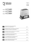
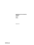
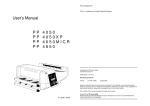
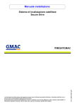
User Manual
Repeatit
BS 100/200/300 Series
Revision 1.1
Page 2 of 14
Installation
The Repeatit Base Station (BS) should always be mounted on the highest possible place with its
antenna having clear line of sight to all clients.
Together with the BS, the following equipment is provided in your box:
•
•
•
•
Base Station
Power over Ethernet adaptor
Mounting kit
Installation Guide
Hardware setup
Figure 1 - Hardware setup
The BS should be connected to the Power over Ethernet (POE) adaptor’s P+DATA OUT socket. Since
both data and power is fed over the cable, all eight conductors should be used, and the Ethernet cable
shall be straight. To the POE’s DATA IN socket, external equipment can be connected. When
configuring the BS, a computer usually is used, and then the cable between the POE and the computer
should be crossed. If the BS is connected to for example a network switch, the cable between the
switch and the POE adaptor usually is straight.
The BS unit is configured in a browser window. Start your browser and type the following line in the
address field:
http://10.0.0.1
Press Enter. A login window is shown. The default login settings are:
User name: admin
Password: public
Type the user name and the password in the fields provided and press OK. In the browser window.
Page 3 of 14
Base station configuration
The BS is intended to be used together with the Radio Control Software (RCS) developed by Repeatit.
The configurations that can be made directly on the BS are overridden by the RCS as soon as a
connection between the BS and the RCS is established and the BS is synchronized.
Note:
The settings shown in the web interface might not reflect the settings made in the RCS.
BS100, BS200 and BS300 Series requires RCS with at least version 2.7.1.0
This Manual describes how the BS is configured through the Web interface. For RCS configuration
please refer to the RCS manual.
1.2.1
Main window
Figure 2 - The main window.
Regulatory settings
ETSI or ETSI-UK can be set depending on which regulatory domain the equipment is intended to be
used. It controls which channels are available for selection.
Radio Devices
Configuration of the radio device is described in section 1.2.2 and section 1.2.3. The Status tab is
described in section 1.2.4.
Ethernet devices
This is the Ethernet interface of the base station. It can not be configured.
Settings
Network settings are described in section 1.2.5. Password settings are described in section 1.2.8. Access
control settings are described in section 1.2.9.
Page 4 of 14
Utilities
Here, the firmware can be upgraded. Usually, this is done from the RCS.
Restore to Default
Pressing this button restores the unit to factory defaults. The unit will automatically reboot when
Restore to Default is performed.
Reboot device
Reboots the device.
Page 5 of 14
1.2.2
Configure tab – Master mode
A radio interface can be configured in two different ways; either as a master or as a client. The Master
mode is shown in Figure 3. To store and apply changes, press Apply.
If BS is configured to be used with an RCS server there will be a warning in red saying that it is
configured by an RCS server. The settings shown might not reflect the actual settings used by the BS.
Figure 3 - Radio device in Master mode.
Page 6 of 14
Basic settings
Radio mode:
Master/Slave.
SSID:
Wireless network name. This is the name that the customers will see
when they perform a scan from their CPEs (Client Premise Equipment).
Broadcast SSID:
Tells whether the SSID should be visible when a scan is performed
or not.
Advanced settings
Preamble:
What type of preamble should be used for the radio transmission. Some old
802.11b units only supports long preamble so this parameter is available to
support also these clients. The normal setting for this parameter is short.
Note: This setting is only valid when mode is 802.11bg
AP Bridge:
Should the BS bridge between clients or not. If disabled two Clients connected to
the same radio interface will not be able to communicate directly with each other.
Flood unknown:
Enabling this will make the BS send packets addressed to unknown receivers to all
associated clients instead of dropping them. .
Frequency:
The frequency band to use.
802.11A, In this mode the BS will work as a standard 802.11A BS, it will only use
the modulations specified for 802.11 use.
802.11N, In this mode the BS will work in both 11Aand 11N mode. It will accept
both types of units at the same time.
802.11G, if a radiocard supporting also 2.4 GHz channels is used in the BS this
choise is also valid. The BS will work on 2.4 GHz channels accepting both 11N
and 11G clients.
Channel:
Within each frequency band, a number of different channels are available.
Radar detection:
Mandatory for the 5 GHz bands in most European countries. Check your national
regulations.
DFS CAC Policy:
This controls how the BS should handle the mandatory Radar Scan time.
Regulatory = use the time stated by the regulatories, normaly 1min scan time
before a new channel can be used.
Custom = You can specify your own time.
Off = do not perform any Radar scan before using the channel.
Note:
The radar scan is mandatory in most Countries.
Scan time on ch 120-128 is 10min.
Custom CAC wait
time:
If DFS CAC Policy is configured as custom the time specified here will be used as
the scan time before starting to use the channel configured.
Guard interval
When running on 802.11N the guard time between consecutive OFDM symbols
can be choosen to be short or long. BS will support both long and short when
receiving, this parameter controls if short or long should be used when
transmitting.
Note:
If 20MHz channel bandwidth is used only long guard interval is supported.
Channel bandwidth:
The 802.11N standard specifies two channel bandwidths 20MHz and 40 MHz. If
20MHz is used BS will only use one 20MHz channel. If 20/40 is used BNs will
use 20 or 40 MHz channel dynamically depending on the connecting clients.
BS will automatically reduce its bandwidth to 20MHz if the extra channel is
occupied. When the extra channel is free again BS will automatically use 40MHz
again.
Page 7 of 14
Antenna gain:
The gain of the antenna in use. This parameter is used to calibrate the radar
detection so that it is not over sensitive when using a large antenna.
Rate:
The available rates are different in various standards. The default value is Auto.
RTS/CTS:
Request to Send/Clear to Send threshold, datapackets larger than this value will be
fragmented into several small packets.
Note: For optimal 802.11N performance leave this empty.
Frag size:
Fragmentation of packets. Leave out for default.
Tx power:
The transmit power from the radio device (this is not the eirp value, i.e. the
antenna gain is not included).
Distance:
Approximate distance to CPE located at furthest place.
Note:
Always configure this value to reflect the furthest CPE connected. To minimize
problems add an extra margin when configure the distance.
Encryption settings
WPA1&2 are available together with ciphers TKIP and CCMP/AES.
The BS and clients need to use the same setting, or the ”both” setting that allows either type.
The TKIP cipher has a hardware limit of around 23 concurrent clients.
There is also support for legacy WEP encryption.
Be advised that the way to crack WEP encryption is well-known and fast.
If the wireless network makes use of WEP keys, the WEP keys settings must be configured in the BS.
To adjust the WEP settings, change the selection from Disabled to either WEP 128-bit or WEP 64-bit.
The WEP key consists of hexadecimal numbers (0-9 and A-F), and the length of the key depends on
the chosen key size (64 or 128 bits). If a 64-bit key is used, ten hex numbers shall be typed in the WEP
key field. If a 128-bit key is used, 26 hex numbers shall be typed in. Observe that the same key set has
to be used on the CPE side of the connection.
The Authentication method used is Shared key. It is also important that the right WEP key number to
use is chosen. For example, if the BS uses WEP key #1, the CPEs also have to use this key number
Associated stations
Here, all associated stations should be presented when the CPEs are connected. If the RCS not is used,
the clients (CPEs and other BS in client mode) have to be enabled under the Access tab (see section
1.2.9).
Page 8 of 14
1.2.3
Configure tab – Client mode
For client mode settings, check Figure 4.
Figure 4 - Radio device slave mode.
Basic settings
Master SSID:
Master BSSID:
mainly
The SSID set on the Master radio card (the radio device that the
client shall connect to).
The MAC address of the Master radio card. This address can be
found in the Main window (see section 1.2.1) on the Master BS. Optional,
useful if there are two or more APs with the same SSID
For advanced and encryption settings, check section 1.2.2.
Site survey
When the BS is in client mode, it is possible to scan the area for other wireless networks. This can be
done in order to avoid interference or to find the Master BS.
To store changes, press Apply.
Page 9 of 14
1.2.4
Status tab
Each radio card has its own Status tab. This tab shows the current status of the radio interface
If several SUs are connected the signal strength is the average signal over all SUs.
Figure 5 - The status tab.
Page 10 of 14
1.2.5 Tools tab
The tools tab has two tools, Site Survey and spectrum graph. With the Site Survey
tool You can perform a Site Survey even if radio is working in Master mode.
The Spectrum graph presents a graph over the available channels and the level of
interference thet the radio has sensed on the channels.
There are two bars per channel, a blue bar showing the signal level of regular OFDM
data-frames and a red bar that shows the signal level of interfering signals received by
the radio.
The Spectrum analyzer takes a snapshot of the levels on each channel and the values
can vary between consecutive sweeps. To get a good picture it is recommended to run
the analyzer a couple of times.
The spectrum analyzer can be configured to run automatically at regular intervals.
Note: During a Site Survey and spectrum analysis wireless traffic will be interrupted.
Figure 6 - The Network tab.
Page 11 of 14
1.2.6 QoS tab
On the QoS tab it is possible to change the WMM settings used by the BS and the
CPEs connected to the BS.
Enable WME:
Yes or No, if yes WMM is enabled and with No it is disabled.
Param Mode:
Auto: Default settings is used, these settings are optimized for
good performance in a multipoint setup.
Manual:
If configured as Manual it is possible setup your own WMM
settings.
Own Settings:
Theese settings is the ones used by the BS.
BSS Settings:
Theese settings are the ones provided to the CPEs and used by
the CPEs.
Figure 7 - The QoS tab.
Page 12 of 14
1.2.7
The Network tab
This is usually the tab that first is accessed when configuring the BS. A screen-shot is shown in
Figure 8.
Figure 8 - The Network tab.
TCP/IP Settings
This is the IP settings for the BS.
RCS settings
If enabled, the IP address of the RCS can be typed in. It is also possible to choose which port the traffic
between the BS and the RCS shall use. The default port number is 9998
Observe that the RCS and the base station need to have the same port selected.
VLAN settings
To use the base station in a VLAN, set the vlan ID here. NB. setting a VLAN is a good way to loose
contact with your BS! Don't touch this setting unless you know what you are doing.
SNMP Configuration:
At this section you can configure the SNMP settings.
1.2.8
Password tab
Under this tab, the password can be changed. To do this, type the new password in the two boxes
provided. Press Apply.
1.2.9
Access tab
When no RCS is used, the BS uses an internal accept list that can be set up to list alloved clients
“Accept” or not allowed clients “Deny”. To add a client to the list, type the client side MAC address in
Page 13 of 14
the Master BS Add MAC field on the form 00:11:22:33:44:55 and press Add (see Figure 9). When all
clients are added, press Apply.
Figure 9 - Access control tab. In this example, one client is added.
Configuration of BS when RCS is used
If a connection between the BS and the RCS is established, the only settings that have to be made on
the BS are network settings (see section 1.2.5). When the BS has been synchronized from the RCS, no
more configurations have to be done on the BS.
Note: BS 100, BS200 and BS300 Series requires RCS with a least version 2.7.1.0
Configuration of BS when RCS is not used
If no RCS address is provided, more configurations have to be done directly on the BS. Here is a
checklist (refer to Figure 2):
1.
2.
3.
4.
Access the Network Settings tab (section 1.2.5) and change the IP settings for the BS.
Access the Configure tab (section 1.2.2) for each radio card and make all relevant settings.
Access the Access Control tab (section 1.2.9) and add all clients.
Reboot the BS.
Page 14 of 14
Support
On our web site, http://www.tucnetworks.com, you can find the latest upgrades of all firmware,
product news, FAQ and other information related to the products.
Our Warranty
Repeatit AB, Hamngatan 33, S-172 66 Sundbyberg, Sweden, guarantee that our products do not have
any defects regarding material or function upon delivery. All of Repeatit’s products are covered by a 12
month international warranty.
If during the time of warranty the product displays any defects regarding material or function, the
products should be returned to your reseller, who will, according to their own judgment, either repair or
replace the product according to the following conditions:
Conditions
1.
The warranty is only valid in combination with an original receipt issued by the reseller at the date
of delivery or sales. The receipt needs to contain the product’s serial number or similar
identification.
2.
If Repeatit repairs or replaces the product, the repaired or replaced product will be covered by the
original warranty during the remainder of the guarantee period. During repair, some parts might be
replaced. These parts are then the property of Repeatit AB.
3.
The warranty does not cover normal wear and tear, faulty usage or handling, or other usage other
than the one prescribed by Repeatit AB. The warranty does not cover defects caused by accidents.
4.
The warranty is not valid if service is performed on the product by a Repeatit non-authorised
person or company.
5.
The warranty is not valid if any products that are not Repeatit original accessories are used with
the product.
6.
There is no warranty, written or oral, other than this printed warranty.