1
Actions
7
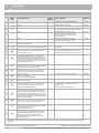
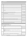
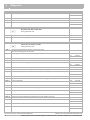
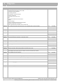
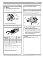
box 274
box 278
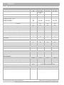
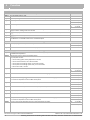
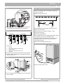
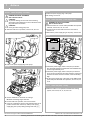
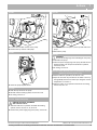
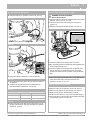
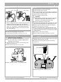
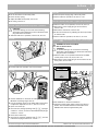
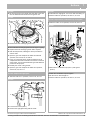
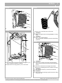
z Fit new plate heat exchanger.
z Renew the four O-rings if necessary.
z Fit the new pressure relief valve and all other components
by following the above procedure in reverse.
z Refit the plate heat exchanger and secure with the two
screws.
z Fill the heating system, vent it of air and place the boiler
into operation, see box 52 to 58.
z Open the cold water service valve.
z Open the hot water tap in order to clean the new plate heat
exchanger (inside).
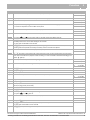
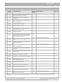
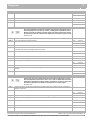
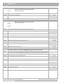
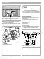
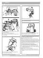
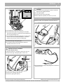
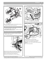
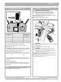
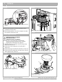
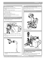
box 279 Replace the turbine flowmeter
z Close the hot water tap.
z Fill the heating system, see box 52.
z Fit the casing and place the boiler into operation,
see box 51, 54 or 55.
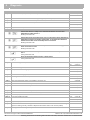
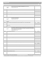
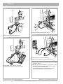
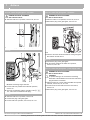
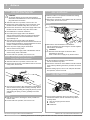
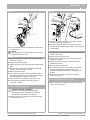
box 275 Replace the pressure relief valve
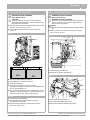
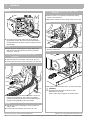
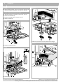
z Take the boiler out of operation and drain the heating
system, see box 48 to 50.
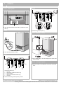
box 276
1
2
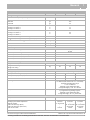
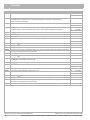
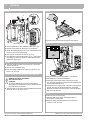
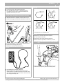
z Remove the stop spring.
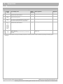
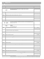
box 280
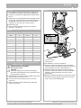
z Remove the stop spring (item 2) of the pressure relief
valve.
z Remove the pressure relief valve (item 1) in the direction
of the arrow.
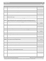
box 277
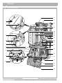
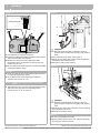
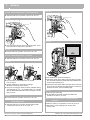
z Use a screwdriver to lever out the turbine flowmeter.
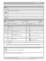
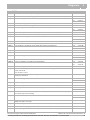
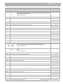
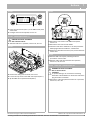
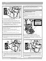
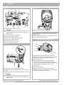
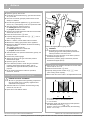
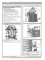
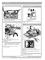
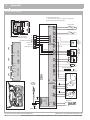
box 281 Replace the DBA control panel
z Release the pressure relief valve from the section of
condendsate outlet pipework by pulling in the direction of
the arrow.
We reserve the right to make technical modifications
H
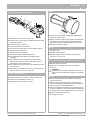
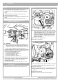
DANGER OF FATAL ACCIDENT
due to electric shock
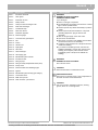
z Take the boiler out of operation and remove the DBA
control panel, see box 43, 44, 47, 63 or 70.
Buderus Ltd. • http://www.buderus-domestic.co.uk
Servicing manual Gas condensing boiler Buderus 500-24/S, 500-24/C and 500-28/C • Issued 02/2006
73