1
GETTING STARTED GUIDE
TerraSync™ software
GETTING STARTED GUIDE
TerraSync™ software
Version 5.30
Revision B
May 2012
F
Trimble Navigation Limited
10355 Westmoor Drive
Suite #100
Westminster, CO 80021
USA
www.trimble.com
Legal Notices
Copyright and Trademarks
©2000—2012, Trimble Navigation Limited. All rights reserved.
Portions of the software are copyright © 1995-2008 LizardTech, Inc.
All rights reserved. MrSID® is protected by U.S. Patent No. 5,710,835.
Foreign Patents Pending. For STL support, the software uses the
Moscow Center for SPARC Technology adaptation of the SGI
Standard Template Library. Copyright © 1994 Hewlett-Packard
Company, Copyright © 1996 1997 Silicon Graphics Computer
Systems, Inc., Copyright © 1997 Moscow Center for SPARC
Technology.
Trimble, the Globe & Triangle logo, GeoExplorer, GPS Pathfinder,
Juno, Nomad, Recon, and Yuma are trademarks of Trimble
Navigation Limited, registered in the United States and in other
countries. GeoBeacon, GeoXH, GeoXT, GPS Analyst, H-Star,
TerraSync, and VRS are trademarks of Trimble Navigation Limited.
MrSID® and LizardTech™ are trademarks of LizardTech, Inc. and are
used with permission.
Microsoft, ActiveSync, Windows, Windows Mobile, and Windows
Vista are either registered trademarks or trademarks of Microsoft
Corporation in the United States and/or other countries.
The Bluetooth word mark and logos are owned by the Bluetooth
SIG, Inc. and any use of such marks by Trimble Navigation Limited
is under license.
All other trademarks are the property of their respective owners.
Release Notice
This is the May 2012 release (Revision B) of the TerraSync Software
Getting Started Guide. It applies to version 5.30 of the TerraSync
software.
End User License Agreement
TerraSync Software
IMPORTANT, READ CAREFULLY. THIS END USER LICENSE
AGREEMENT (“AGREEMENT”) IS A LEGAL AGREEMENT
BETWEEN YOU (either an individual or a single entity) AND
TRIMBLE NAVIGATION LIMITED and its affiliates (collectively,
“Trimble”) and applies to the TerraSync™ software product
Standard,, Juno, Professional, or Centimeter editions provided
herewith, including any accompanying written materials, such as a
user's guide or product manual, as well as any “online” or electronic
documentation (collectively, “Software”). This Agreement will also
apply to any Software error corrections, updates and upgrades
subsequently furnished by Trimble, unless such are accompanied by
different license terms and conditions which will govern their use.
BY CLICKING “YES” OR “I ACCEPT” IN THE ACCEPTANCE
BOX,OR BY INSTALLING, COPYING OR OTHERWISE USING THE
SOFTWARE, YOU AGREE TO BE BOUND BY THE TERMS OF THIS
AGREEMENT. IF YOU DO NOT AGREE TO THE TERMS OF THIS
AGREEMENT, PROMPTLY RETURN THE UNUSED SOFTWARE
AND ANY ACCOMPANYING TRIMBLE PRODUCT TO THE PLACE
FROM WHICH YOU OBTAINED THEM FOR A REFUND.
This Software is protected by copyright laws and international
copyright treaties, as well as other intellectual property laws and
treaties. The Software is licensed, not sold.
Third Party Software: The following third party software is or may
be included with the Software and is subject to this Agreement:
– ECW JPEG 2000 Runtime, copyright © 2006 Earth Resource
Mapping Limited. All rights reserved.
– MrSID® Decoder Runtime, copyright © 1995-1999 LizardTech, Inc.
All rights reserved. The U.S. Government has reserved rights to the
MrSID technology as described in Section 5 below.
1 SOFTWARE PRODUCT LICENSE
1.1 License Grant - General. Subject to the terms and conditions of
this Agreement and your payment of applicable license fees,
Trimble grants you a non-exclusive, non-transferable (except as
expressly provided below) license right to install, activate and use
one (1) copy of the Software (in machine-readable form) on any
computer hardware and operating system for which it was intended
4 TerraSync Software Getting Started Guide
for your internal business needs. Your activation of the Software
shall be effected in accordance with Trimble’s usual and customary
activation procedures current on the date of activation.
You may use the Software on only one computer at any time. You
may move the Software from one computer to another, provided
that you first uninstall the Software from the original computer,
deactivate it as required, and then reinstall it on the new computer.
You may authorize the personnel associated with your business to
use the Software, but likewise, use is limited to only one person at
one time, on one computer at one time. You may also store or install
a copy of the Software on a storage device, such as a network server,
used only to install the Software on your other computers over an
internal network; but in such case you must acquire and dedicate a
license for each separate computer on which the Software is
installed from the storage device. A license for the Software may not
be shared or used concurrently on different computers.
1.2 License Grant - Multi-Seat Products.
(a) If the Software was purchased as part of a Trimble Multi-Seat
product, then subject to the terms and conditions of this Agreement
and your pre-payment of the applicable license fee specified on the
Cover Sheet, Trimble grants you a non-exclusive, fully paid up right
to use the Software (in machine-readable form) on any computer
hardware and operating system for which it was intended. Such use
is limited to use of the Software at a single installation site; and is
further limited to the total number of installations/seat licenses
specified by the Multi-Seat product purchased. A seat license for the
Software may not be shared or used concurrently on different
computers/devices.
(b) If the Software was purchased as part of a Trimble Educational
Multi-Pack, the above license grant is conditioned on the following:
(1) This Software is licensed to you as an educational institution for
the sole purpose of training, instruction and research and for no
other purpose. You shall not use the Software for commercial,
professional, or for-profit purposes; (2) At the time of Software
installation on each personal computer or workstation you shall
register the Software with Trimble, if and as directed to do so by the
Software installation program; (3) You shall maintain adequate
records of usage of the licensed Software by your authorized users
to assure compliance with the limitations of this Site License; and
shall make such records available to Trimble upon reasonable
request.
1.3 Other Rights and Limitations.
(1) You may not copy, modify, make derivative works (except for
Customized Applications) of, rent, lease, sell, sublicense, distribute
or transfer the Software, in whole or in part, except as otherwise
expressly authorized under this Agreement, and you agree to use all
commercially reasonable efforts to prevent its unauthorized use
and disclosure. You may make one copy of the Software for archival
purposes. Disabling any licensing control features is prohibited.
(2) The Software contains valuable trade secrets proprietary to
Trimble and its suppliers. To the extent permitted by applicable law,
you shall not, nor allow any third party to copy, decompile,
disassemble or otherwise reverse engineer the Software, or attempt
to do so; provided, however, that to the extent any applicable
mandatory laws give you the right to perform any of the
aforementioned activities without Trimble's consent in order to
gain certain information about the Software for purposes specified
in the respective statutes (e.g., interoperability), you hereby agree
that, before exercising any such rights, you shall first request such
information from Trimble in writing detailing the purpose for which
you need the information. Only if and after Trimble, at its sole
discretion, partly or completely denies your request, may you
exercise such statutory rights.
(3) The Software is licensed as a single product. You may not
separate its component parts for use on more than one computer
except as specifically authorized in this Agreement.
(4) You may not rent, lease or lend the Software unless you are a
reseller of Trimble products under separate written agreement with
Trimble and authorized by Trimble to do so.
(5) No service bureau work is permitted. For purposes of this
Agreement "service bureau work" shall be deemed to include,
without limitation, use of the Software to process or to generate
output data for the benefit of, or for purposes of rendering services
to any third party over the Internet or other communications
network.
(6) You may permanently transfer all of your rights under this
Agreement, provided you retain no copies, you transfer all of the
Software (including all component parts, the media and printed
materials, any upgrades, and this Agreement) and the recipient
agrees to the terms of this Agreement. If the Software portion is an
upgrade, any transfer must include all prior versions of the Software.
(7) You may not use the Software for performance, benchmark or
comparison testing or analysis, or disclose to any third party or
release any results thereof (all of which information shall be
considered Trimble confidential information) without Trimble's
prior written consent.
(8) You agree to comply with all applicable laws and regulations of
the United States and of other jurisdictions (national, state and
local) to the extent that they may govern your use of the Software.
Without limiting the foregoing, you shall not (directly or indirectly)
export, re-export, import, transfer, or divert the Software in whole or
in part (i) without all necessary authorizations required by law, or
(ii) to any prohibited destination or to any prohibited person, entity
or end user as specified by U.S. export control laws.
(9) To the extent that your use of the Software is limited to a specific
number of installations and/or seat licenses under the above license
grant, you agree to cooperate with Trimble to track the number of
computers, server computers, and other devices with access to the
Software at your site(s) or under your control to ensure compliance
with the license grant and installation restrictions in this
Agreement. In the event the compliance check reveals that the
number of installations or concurrent users of the Software licensed
hereunder exceeds the actual number of licenses obtained by you,
you agree to promptly reimburse Trimble three (3) times the then
current applicable list price for the extra licenses that are required
to be compliant, but that were not obtained, as liquidated damages
and as a reasonable penalty. The foregoing remedy is not exclusive.
1.4 Termination. The license is effective until terminated as
provided herein. You may terminate this Agreement by ceasing all
use of the Software and destroying or returning all copies. Without
prejudice as to any other rights, Trimble may terminate this
Agreement with or without notice if you fail to comply with the
terms and conditions of this Agreement. In such event, you must
cease its use destroy all copies of the Software and of its component
parts.
1.5 Copyright. All title and copyrights in and to the Software
(including but not limited to any images, photographs, animations,
video, audio, music, and text incorporated into the Software), the
accompanying written materials, and any copies of the Software are
owned by Trimble and its suppliers. You shall not remove, cover or
alter any of Trimble's patent, copyright or trademark notices placed
upon, embedded in or displayed by the Software or on its packaging
and related materials.
1.6 U.S. Government Licensee - Restricted Rights. [Applies only to
U.S. Government Licensees] If you are the United States
Government or any agency or contractor thereof, use, duplication or
disclosure of the Software is granted with “Restricted Rights” subject
to the restrictions set forth in this Agreement and as provided in
FAR 52.227.19(c)(2) or subparagraph (c)(1)(ii) of the Rights in
Technical Data and Computer Software clause at DFARS 252.2277013, and/or in similar or successor clauses in the FAR, or the DOD
or NASA FAR Supplement.
2 TIME LIMITED SOFTWARE.
In the event that the Software provided to you is a time limited
version, such as Software provided to Trimble resellers and
distributors for sales demonstration purposes under a
demonstration license or to prospective end user customers for
evaluation purposes under an evaluation license, ("Time Limited
Software"), then the terms of this Section 2 shall apply, and
supersede anything else to the contrary (including, without
limitation, the limited warranty under Section 3):
2.1 Use and Limited Term; Disabling Mechanism. You may use Time
Limited Software solely for the purpose for which it is provided to
you by Trimble (e.g., reseller/distributor demonstration or end user
evaluation), and only for the limited period of time specified by
Trimble. If no such limited time period is specified, then you may
use the Time Limited Software for 14 days from the date of its initial
installation. The Time Limited Software contains a disabling
mechanism, which will prevent the Time Limited Software from
functioning after the end of the limited term. In the event that you
subsequently acquire a paid license to the Software, then your
continued use of the Software will be governed by the terms of this
Agreement (except for this Section 2). Resale or other distribution of
Time Limited Software is prohibited.
2.2 No Warranties. YOU EXPRESSLY ACKNOWLEDGE AND AGREE
THAT THE TIME LIMITED SOFTWARE IS PROVIDED TO YOU
"AS-IS" WITHOUT WARRANTY OF ANY KIND, EITHER EXPRESS
OR IMPLIED, INCLUDING, BUT NOT LIMITED TO, THEIMPLIED
WARRANTIES OF MERCHANTABILITY, FITNESS FOR A
PARTICULAR PURPOSE, NONINTERFERENCE, TITLE AND
NONINFRINGEMENT. YOU ASSUME ALL RISK AS TO THE
QUALITY AND PERFORMANCE OF THE TIME LIMITED
SOFTWARE.
3 LIMITED WARRANTY.
3.1 Limited Warranty. Trimble warrants that the Software will
perform substantially in accordance with the accompanying
written materials (i.e., applicable user's guide or product manual)
for a period of either 90 days for TerraSync Standard edition, or one
(1) year for TerraSync Juno, Professional, and Centimeter editions,
from the date of purchase of your license hereunder. This limited
warranty gives you specific legal rights, you may have others, which
vary from state/jurisdiction to state/jurisdiction. The above limited
warranty does not apply to error corrections, updates or upgrades of
the Software after expiration of the limited warranty period, which
are provided “AS IS” and without warranty unless otherwise
specified in writing by Trimble. ADDITIONALLY, TRIMBLE MAKES
NO WARRANTIES, EITHER EXPRESS OR IMPLIED, REGARDING
THE CUSTOMIZED APPLICATIONS OR USE OF THE SOFTWARE
WITH ANY THIRD PARTY HARDWARE OR EQUIPMENT. Because
the Software is inherently complex and may not be completely free
of nonconformities, defects or errors, you are advised to verify your
work. Trimble does not warrant that the Software will operate error
free or uninterrupted, will meet your needs or expectations, or that
all nonconformities can or will be corrected.
3.2 Customer Remedies. Trimble's and its suppliers' entire liability,
and your sole remedy, with respect to the Software shall be either, at
Trimble's option, (a) repair or replacement of the Software, or (b)
return of the license fee paid for any Software that does not meet
Trimble's limited warranty. The foregoing limited warranty is void if
failure of the Software has resulted from (1) accident, misuse, abuse,
or misapplication; (2) alteration or modification of the Software
without Trimble's authorization; (3) interaction with software or
hardware not supplied or supported by Trimble; (4) your improper,
inadequate or unauthorized installation, maintenance or storage; or
( f ) if you violate the terms of this Agreement. Any replacement
Software will be warranted for the remainder of the original
warranty period or 30 days, whichever is longer.
3.3 NO OTHER WARRANTIES. TO THE MAXIMUM EXTENT
PERMITTED BY APPLICABLE LAW, TRIMBLE AND ITS
SUPPLIERS DISCLAIM ALL OTHER WARRANTIES, TERMS, AND
CONDITIONS, EITHER EXPRESS OR IMPLIED, BY STATUTE,
COMMON LAW OR OTHERWISE, INCLUDING BUT NOT
LIMITED TO, IMPLIED WARRANTIES, TERMS, AND
CONDITIONS OF MERCHANTABILITY AND FITNESS FOR A
PARTICULAR PURPOSE, TITLE, AND NONINFRINGEMENT
WITH REGARD TO THE SOFTWARE, ITS SATISFACTORY
QUALITY, AND THE PROVISION OF OR FAILURE TO PROVIDE
SUPPORT SERVICES. TO THE EXTENT ALLOWED BY
APPLICABLE LAW, IMPLIED WARRANTIES, TERMS AND
CONDITIONS ON THE SOFTWARE ARE LIMITED TO EITHER 90
DAYS FOR TERRASYNC STANDARD EDITION, OR ONE (1) YEAR
FOR TERRASYNC JUNO, PROFESSIONAL, AND CENTIMETER
EDITIONS. Y0U MAY HAVE OTHER LEGAL RIGHTS WHICH VARY
FROM STATE/JURISDICTION TO STATE/JURISDICTION.
The foregoing limited warranty and customer remedy provisions
under Sections 3.1 and 3.2 shall not apply to Software obtained as
freeware without charge (such as for example evaluation or
demonstration copies), whether from Trimble, an authorized
Trimble dealer or otherwise. Such Software obtained without
payment of a license fee is furnished “AS IS” without warranty of any
kind unless the user has separately purchased applicable warranty
and/or support coverage.
3.4 LIMITATION OF LIABILITY. YOU ASSUME ALL RISK AS TO
THE RESULTS AND PERFORMANCE OF THE SOFTWARE. TO
THE MAXIMUM EXTENT PERMITTED BY APPLICABLE LAW, IN
NO EVENT SHALL TRIMBLE OR ITS SUPPLIERS BE LIABLE FOR
ANY SPECIAL, INCIDENTAL, INDIRECT OR CONSEQUENTIAL OR
PUNITIVE DAMAGES, HOWEVER CAUSED AND REGARDLESS
OF THE THEORY OF LIABILITY (INCLUDING, WITHOUT
LIMITATION, DAMAGES FOR LOSS OF BUSINESS PROFITS,
BUSINESS INTERRUPTION, LOSS OF BUSINESS INFORMATION,
OR ANY OTHER PECUNIARY LOSS), ARISING OUT OF THE USE
OR INABILITY TO USE THE SOFTWARE, OR THE PROVISION OF
OR FAILURE TO PROVIDE SUPPORT SERVICES, EVEN IF
TRIMBLE HAS BEEN ADVISED OF THE POSSIBILITY OF SUCH
DAMAGES, AND NOTWITHSTANDING ANY FAILURE OF
ESSENTIAL PURPOSE OF ANY EXCLUSIVE REMEDY PROVIDED
IN THIS AGREEMENT.IN NO EVENT SHALL TRIMBLE'S TOTAL
TerraSync Software Getting Started Guide 5
LIABILITY IN CONNECTION WITH THIS AGREEMENT OR THE
SOFTWARE, WHETHER BASED ON CONTRACT, WARRANTY,
TORT (INCLUDING NEGLIGENCE) EXCEED THE ACTUAL
AMOUNT PAID TO TRIMBLE FOR USE OF THE SOFTWARE
GIVING RISE TO THE CLAIM. BECAUSE SOME STATES AND
JURISDICTIONS DO NOT ALLOW THE EXCLUSION OR
LIMITATION OF LIABILITY FOR CONSEQUENTIAL OR
INCIDENTAL DAMAGES, THE ABOVE LIMITATION MAY NOT
APPLY TO YOU.
3.5 PLEASE NOTE: THE ABOVE TRIMBLE LIMITED WARRANTY
PROVISIONS MAY NOT APPLY TO SOFTWARE PRODUCTS
PURCHASED IN THOSE JURISDICTIONS (SUCH AS COUNTRIES
OF THE EUROPEAN ECONOMIC COMMUNITY) IN WHICH
PRODUCT WARRANTIES ARE OBTAINED FROM THE LOCAL
DISTRIBUTOR. IN SUCH CASE, PLEASE CONTACT YOUR
TRIMBLE DEALER FOR APPLICABLE WARRANTY
INFORMATION.
4 GENERAL.
4.1 This Agreement shall be governed by the laws of the State of
California and applicable United States Federal law without
reference to "conflict of laws" principles or provisions. The United
Nations Convention on Contracts for the International Sale of
Goods will not apply to this Agreement. Jurisdiction and venue of
any dispute or court action arising from or related to this
Agreement or the Software shall lie exclusively in or be transferred
to the courts the County of Santa Clara, California, and/or the
United States District Court for the Northern District of California.
You hereby consent and agree not to contest, such jurisdiction,
venue and governing law.
4.2 Section 4.1 notwithstanding, if you acquired this product in
Canada, this Agreement is governed by the laws of the Province of
Ontario, Canada. In such case each of the parties to this Agreement
irrevocably attorns to the jurisdiction of the courts of the Province
of Ontario and further agrees to commence any litigation that may
arise under this Agreement in the courts located in the Judicial
District of York, Province of Ontario. If you acquired this product in
the European Union, this Agreement is governed by the laws of The
Netherlands, excluding its rules governing conflicts of laws and
excluding the United Nations Convention on the International Sale
of Goods. In such case each of the parties to this Agreement
irrevocably attorns to the jurisdiction of the courts of The
Netherlands and further agrees to commence any litigation that
may arise under this Agreement in the courts of The Hague, The
Netherlands.
4.3 Reservation of Rights. Trimble reserves all rights not expressly
granted by this Agreement.
4.4 Official Language. The official language of this Agreement is
English. For purposes of interpretation, or in the event of a conflict
between English and versions of this Agreement in any other
language, the English language version shall be controlling.
6 TerraSync Software Getting Started Guide
5 THIRD PARTY LICENSE RIGHTS
5.1 Portions of this Software incorporating MrSID functionality are
provided under license from LizardTech, Inc. The MrSID software is
protected by United States Copyright Law and International Treaty
provisions and by U.S. Patent No. 5,710,835. Foreign patents are
pending. Some of the MrSID technology was developed through a
project at the Los Alamos National Laboratory (LANL) funded by
the U.S. Government, managed under contract by the Regents of the
University of California (University). The U.S. Government and the
University have reserved rights in the Technology, including the
following: (a) the U.S. Government has a non-exclusive,
nontransferable, irrevocable, paid-up license to practice or have
practiced throughout the world, for or on behalf of the United
States, inventions covered by the University's Patent Rights, and has
other rights under 35 U.S.C. § 200-212 and applicable implementing
regulations and under the U.S. Department of Energy (DOE)
Assignment and Confirmatory License through which the DOE's
rights in the Technology were assigned to the University; (b) Under
35 U.S.C. § 203, the DOE has the right to require LizardTech to grant
a non-exclusive, partially exclusive or exclusive license under U.S.
Patent No. 5,710,835 in any field of use to a responsible applicant(s)
upon terms reasonable under the circumstances, if LizardTech does
not adequately attempt to commercialize the MrSID Technology.
See, 37 CFR 401.6; (c) The University makes no warranty or
representation as to the validity or scope of Patent No. 5,710,835,
and neither the Government nor the University have any obligation
to furnish any know-how, technical assistance, or technical data in
connection with MrSID software. For further information about
these provisions, contact Lizardtech, Inc., The Exchange Building,
821 Second Avenue, 18th Floor, Seattle, Washington 98104.
5.2 The ECW JPEG 2000 Runtime component(s) of this Software
allowing decompression of ECW JPEG 2000 images is provided
under license from Earth Resource Mapping Limited, 2
AbbotsfordRd., West Leederville, Western Australia 6007. Any
redistribution of such Runtime component(s) by you is prohibited.
Trimble Navigation Limited / Trimble Europe B.V.
TerraSync Software
End User License Agreement
Rev. 2011 August 10
Contents
1
Introduction . . . . . . . . . . . . . . . . . . . . . . . . . . . . . . . . . . . 13
Documentation conventions . . .
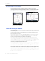
About the TerraSync software . .
TerraSync software editions . . .
Finding additional information .
Technical assistance . . . . . . . .
Technical support . . . . .
Windows error reporting .
2
.
.
.
.
.
.
.
.
.
.
.
.
.
.
.
.
.
.
.
.
.
.
.
.
.
.
.
.
.
.
.
.
.
.
.
.
.
.
.
.
.
.
.
.
.
.
.
.
.
.
.
.
.
.
.
.
.
.
.
.
.
.
.
.
.
.
.
.
.
.
.
.
.
.
.
.
.
.
.
.
.
.
.
.
.
.
.
.
.
.
.
.
.
.
.
.
.
.
.
.
.
.
.
.
.
.
.
.
.
.
.
.
.
.
.
.
.
.
.
.
.
.
.
.
.
.
.
.
.
.
.
.
.
.
.
.
.
.
.
.
.
.
.
.
.
.
.
.
.
.
.
.
.
.
.
.
.
.
.
.
.
.
.
.
.
.
.
.
.
.
.
.
.
.
.
.
.
.
.
.
.
.
.
.
.
.
.
.
.
.
.
.
.
.
.
.
.
.
.
.
.
.
.
.
.
.
.
.
.
.
.
.
.
.
.
.
.
.
.
.
.
.
.
.
.
.
.
.
.
.
.
.
.
.
.
.
.
.
.
.
.
.
.
.
.
.
.
.
.
.
.
.
.
.
.
.
.
.
.
.
.
.
.
.
.
.
.
.
.
.
.
.
.
14
14
15
15
16
16
16
Software Installation and Activation . . . . . . . . . . . . . . . . . . . . . 17
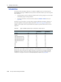
System requirements. . . . . . . . . . . . . . . . . . . . . . . . . . . . . . . . . . . . . . . . . . . . . . . 18
Computer specifications . . . . . . . . . . . . . . . . . . . . . . . . . . . . . . . . . . . . . . . . 18
Required software . . . . . . . . . . . . . . . . . . . . . . . . . . . . . . . . . . . . . . . . . . . . 18
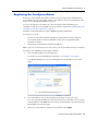
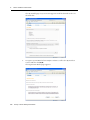
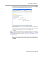
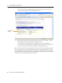
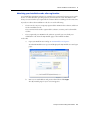
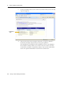
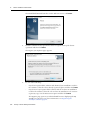
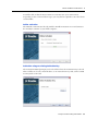
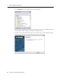
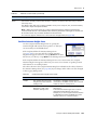
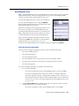
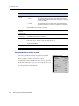
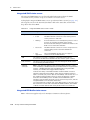
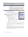
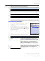
Registering the TerraSync software . . . . . . . . . . . . . . . . . . . . . . . . . . . . . . . . . . . . . . 19
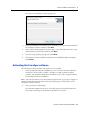
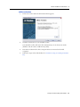
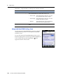
Obtaining your installation code after registration. . . . . . . . . . . . . . . . . . . . . . . . 23
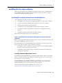
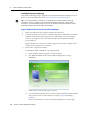
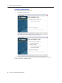
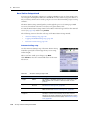
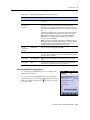
Installing the TerraSync software . . . . . . . . . . . . . . . . . . . . . . . . . . . . . . . . . . . . . . . 25
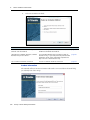
Installing the TerraSync software onto a handheld device . . . . . . . . . . . . . . . . . . . 25
Installing the TerraSync software onto an office computer running a Windows operating
system. . . . . . . . . . . . . . . . . . . . . . . . . . . . . . . . . . . . . . . . . . . . . . . . . . 31
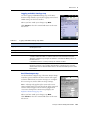
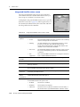
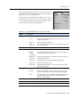
Activating the TerraSync software . . . . . . . . . . . . . . . . . . . . . . . . . . . . . . . . . . . . . . 33
Starting the TerraSync software. . . . . . . . . . . . . . . . . . . . . . . . . . . . . . . . . . . . 39
Updating the TerraSync software . . . . . . . . . . . . . . . . . . . . . . . . . . . . . . . . . . . . . . . 40
Installing a translation of the TerraSync software . . . . . . . . . . . . . . . . . . . . . . . . . . . . . 40
Run the file to complete the installation. . . . . . . . . . . . . . . . . . . . . . . . . . . . . . . 40
Install fonts onto the Windows Mobile powered device . . . . . . . . . . . . . . . . . . . . 40
Compatible GNSS receivers. . . . . . . . . . . . . . . . . . . . . . . . . . . . . . . . . . . . . . . . . . . 42
Connecting to a receiver . . . . . . . . . . . . . . . . . . . . . . . . . . . . . . . . . . . . . . . . 42
Connecting to external real-time correction devices . . . . . . . . . . . . . . . . . . . . . . 43
3
User Interface and Data Entry . . . . . . . . . . . . . . . . . . . . . . . . . 45
Using the Windows operating system . . . . .
Using the Windows Mobile operating system
Adjusting the backlight . . . . . . . . . .
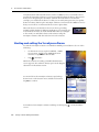
Working with other applications . . . .
Using the on-screen keyboard . . . . . .
Device Lock utility . . . . . . . . . . . . .
Starting and exiting the TerraSync software .
Section structure . . . . . . . . . . . . . . . . . .
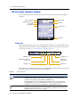
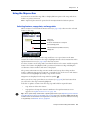
The TerraSync software display . . . . . . . . .
Status bar. . . . . . . . . . . . . . . . . . .
Interacting with the TerraSync software. . . .
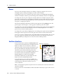
Screens . . . . . . . . . . . . . . . . . . . .
.
.
.
.
.
.
.
.
.
.
.
.
.
.
.
.
.
.
.
.
.
.
.
.
.
.
.
.
.
.
.
.
.
.
.
.
.
.
.
.
.
.
.
.
.
.
.
.
.
.
.
.
.
.
.
.
.
.
.
.
.
.
.
.
.
.
.
.
.
.
.
.
.
.
.
.
.
.
.
.
.
.
.
.
.
.
.
.
.
.
.
.
.
.
.
.
.
.
.
.
.
.
.
.
.
.
.
.
.
.
.
.
.
.
.
.
.
.
.
.
.
.
.
.
.
.
.
.
.
.
.
.
.
.
.
.
.
.
.
.
.
.
.
.
.
.
.
.
.
.
.
.
.
.
.
.
.
.
.
.
.
.
.
.
.
.
.
.
.
.
.
.
.
.
.
.
.
.
.
.
.
.
.
.
.
.
.
.
.
.
.
.
.
.
.
.
.
.
.
.
.
.
.
.
.
.
.
.
.
.
.
.
.
.
.
.
.
.
.
.
.
.
.
.
.
.
.
.
.
.
.
.
.
.
.
.
.
.
.
.
.
.
.
.
.
.
.
.
.
.
.
.
.
.
.
.
.
.
.
.
.
.
.
.
.
.
.
.
.
.
.
.
.
.
.
.
.
.
.
.
.
.
.
.
.
.
.
.
.
.
.
.
.
.
.
.
.
.
.
.
.
.
.
.
.
.
.
.
.
.
.
.
.
.
.
.
.
.
.
.
.
.
.
.
.
.
.
.
.
.
.
.
.
.
.
.
.
.
.
.
.
.
.
.
.
.
.
.
.
.
.
.
.
.
.
.
.
.
.
.
.
.
.
.
.
.
.
.
.
.
.
.
46
46
46
46
47
47
48
49
50
50
55
55
TerraSync Software Getting Started Guide
7
Contents
Graphical screens. . . . . . . . .
Forms . . . . . . . . . . . . . . . .
Lists . . . . . . . . . . . . . . . . .
Buttons . . . . . . . . . . . . . . .
Keyboard shortcuts . . . . . . .
Data entry fields . . . . . . . . .
Auto-incrementing attributes .
Pop-up messages . . . . . . . . .
Tooltips . . . . . . . . . . . . . . .
Sound . . . . . . . . . . . . . . . .
Color. . . . . . . . . . . . . . . . .
4
.
.
.
.
.
.
.
.
.
.
.
.
.
.
.
.
.
.
.
.
.
.
.
.
.
.
.
.
.
.
.
.
.
.
.
.
.
.
.
.
.
.
.
.
.
.
.
.
.
.
.
.
.
.
.
.
.
.
.
.
.
.
.
.
.
.
.
.
.
.
.
.
.
.
.
.
.
.
.
.
.
.
.
.
.
.
.
.
.
.
.
.
.
.
.
.
.
.
.
.
.
.
.
.
.
.
.
.
.
.
.
.
.
.
.
.
.
.
.
.
.
.
.
.
.
.
.
.
.
.
.
.
.
.
.
.
.
.
.
.
.
.
.
.
.
.
.
.
.
.
.
.
.
.
.
.
.
.
.
.
.
.
.
.
.
.
.
.
.
.
.
.
.
.
.
.
.
.
.
.
.
.
.
.
.
.
.
.
.
.
.
.
.
.
.
.
.
.
.
.
.
.
.
.
.
.
.
.
.
.
.
.
.
.
.
.
.
.
.
.
.
.
.
.
.
.
.
.
.
.
.
.
.
.
.
.
.
.
.
.
.
.
.
.
.
.
.
.
.
.
.
.
.
.
.
.
.
.
.
.
.
.
.
.
.
.
.
.
.
.
.
.
.
.
.
.
.
.
.
.
.
.
.
.
.
.
.
.
.
.
.
.
.
.
.
.
.
.
.
.
.
.
.
.
.
.
.
.
.
.
.
.
.
.
.
.
.
.
.
.
.
.
.
.
.
.
.
.
.
.
.
.
.
.
.
.
.
.
.
.
.
.
.
.
.
.
.
.
.
.
.
.
.
.
.
.
.
.
.
.
.
.
.
.
.
.
.
.
.
.
.
.
.
.
.
.
.
.
.
.
.
.
.
.
.
.
.
.
.
.
.
.
.
.
.
.
.
.
.
.
.
.
.
.
.
.
.
.
.
.
.
.
.
.
.
.
.
.
.
.
.
.
.
.
.
.
.
.
.
.
.
.
.
.
.
.
.
.
.
.
.
.
.
.
.
.
.
.
.
.
.
.
.
.
.
.
.
.
.
.
.
.
.
.
.
.
.
.
.
.
.
.
.
.
.
.
.
.
.
.
.
.
.
.
.
.
.
.
.
.
.
.
.
.
.
.
.
.
.
.
.
.
.
.
.
.
.
.
.
.
.
.
.
.
.
.
.
.
.
.
.
.
.
56
56
57
58
59
61
66
66
67
67
70
.
.
.
.
.
.
.
.
.
.
.
.
.
.
.
.
.
.
.
.
.
.
.
.
.
.
.
.
.
.
.
.
.
.
.
.
74
74
76
76
.
.
.
.
.
.
.
.
.
.
.
.
.
.
.
.
.
.
.
.
.
.
.
.
.
.
.
.
.
.
.
.
.
.
.
.
.
.
.
.
.
.
.
.
.
.
.
.
.
.
.
.
.
.
.
.
.
.
.
.
.
.
.
.
.
.
.
.
.
.
.
.
.
.
.
.
.
.
.
.
.
.
.
.
.
.
.
.
.
.
.
.
.
.
.
.
.
.
.
.
.
.
.
.
.
.
.
.
.
.
.
.
.
.
.
.
.
.
.
.
.
.
.
.
.
.
.
.
.
.
.
.
.
.
.
.
.
.
.
.
.
.
.
.
. 78
. 83
. 85
. 86
. 86
. 87
. 89
. 91
. 93
. 93
. 94
. 94
. 95
. 95
. 96
. 98
. 98
.100
Data Section . . . . . . . . . . . . . . . . . . . . . . . . . . . . . . . . . . 103
New File screen . . . . . . . . . . . . . . . . . . . . . . . . . . . . . . . . . . .
Confirm Antenna Height form . . . . . . . . . . . . . . . . . . . . .
Base Station Setup wizard . . . . . . . . . . . . . . . . . . . . . . . .
Collect Features screen . . . . . . . . . . . . . . . . . . . . . . . . . . . . . .
Collect features in QuickPoint data collection mode . . . . . . .
Collect features in Log Now or Log Later data collection mode.
8
.
.
.
.
.
.
.
.
.
.
.
Map Section. . . . . . . . . . . . . . . . . . . . . . . . . . . . . . . . . . . . 77
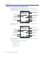
Elements and controls in the Map section . . . . . . . . . . . . . . . . . . . . . . . .
Map tools . . . . . . . . . . . . . . . . . . . . . . . . . . . . . . . . . . . . . . . . . . . . .
Map layers . . . . . . . . . . . . . . . . . . . . . . . . . . . . . . . . . . . . . . . . . . . .
Background Files form . . . . . . . . . . . . . . . . . . . . . . . . . . . . . . . .
Multiple background files . . . . . . . . . . . . . . . . . . . . . . . . . . . . . .
Web map server. . . . . . . . . . . . . . . . . . . . . . . . . . . . . . . . . . . . .
Layer Formatting form . . . . . . . . . . . . . . . . . . . . . . . . . . . . . . . .
Enter Coordinates form . . . . . . . . . . . . . . . . . . . . . . . . . . . . . . . .
Using the Map section . . . . . . . . . . . . . . . . . . . . . . . . . . . . . . . . . . . . .
Selecting features, map points, and waypoints . . . . . . . . . . . . . . . . .
Panning . . . . . . . . . . . . . . . . . . . . . . . . . . . . . . . . . . . . . . . . . .
Zooming . . . . . . . . . . . . . . . . . . . . . . . . . . . . . . . . . . . . . . . . .
Capturing point features using QuickPoint mode from the Map section .
Creating and ending features from the Map section . . . . . . . . . . . . . .
Digitizing positions . . . . . . . . . . . . . . . . . . . . . . . . . . . . . . . . . .
Measuring . . . . . . . . . . . . . . . . . . . . . . . . . . . . . . . . . . . . . . . .
Setting and clearing the navigation start and target . . . . . . . . . . . . . .
Controlling logging from the Map section . . . . . . . . . . . . . . . . . . . .
6
.
.
.
.
.
.
.
.
.
.
.
Software Structure . . . . . . . . . . . . . . . . . . . . . . . . . . . . . . . 73
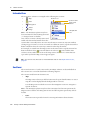
Introduction . . .
Sections . . . . . .
Panes. . . . . . . .
Section structure
5
.
.
.
.
.
.
.
.
.
.
.
TerraSync Software Getting Started Guide
.
.
.
.
.
.
.
.
.
.
.
.
.
.
.
.
.
.
.
.
.
.
.
.
.
.
.
.
.
.
.
.
.
.
.
.
.
.
.
.
.
.
.
.
.
.
.
.
.
.
.
.
.
.
.
.
.
.
.
.
.
.
.
.
.
.
.
.
.
.
.
.
.
.
.
.
.
.
.
.
.
.
.
.
.104
.105
.106
.112
.112
.112
Contents
Collect Base Data form . . . . . . . . . . . .
Base File Logging Settings form . . . . . . .
Attribute entry form . . . . . . . . . . . . . .
Pausing and resuming logging. . . . . . . .
Offset form . . . . . . . . . . . . . . . . . . . .
Distance-Bearing Offset form . . . . . . . .
Distance-Distance Offset form . . . . . . .
Triple Distance Offset form . . . . . . . . .
Bearing-Bearing Offset form . . . . . . . . .
Triple Bearing Offset form . . . . . . . . . .
Vertex form . . . . . . . . . . . . . . . . . . .
Logging Interval form . . . . . . . . . . . . .
Continue Feature form . . . . . . . . . . . .
Existing Files screen . . . . . . . . . . . . . . . . . .
Update Features screen . . . . . . . . . . . . . . . .
Attribute entry form for existing features.
Update status . . . . . . . . . . . . . . . . . .
Marking a feature as updated . . . . . . . .
Updating positions . . . . . . . . . . . . . . .
Filter By form . . . . . . . . . . . . . . . . . .
Filtering features . . . . . . . . . . . . . . . .
Construct Target Offset form . . . . . . . .
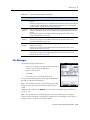
File Manager . . . . . . . . . . . . . . . . . . . . . . .
Send via E-mail form. . . . . . . . . . . . . .
Receive via E-mail form . . . . . . . . . . . .
Read from Shape form. . . . . . . . . . . . .
Write to Shape form . . . . . . . . . . . . . .
Extract Data form . . . . . . . . . . . . . . .
7
.
.
.
.
.
.
.
.
.
.
.
.
.
.
.
.
.
.
.
.
.
.
.
.
.
.
.
.
.
.
.
.
.
.
.
.
.
.
.
.
.
.
.
.
.
.
.
.
.
.
.
.
.
.
.
.
.
.
.
.
.
.
.
.
.
.
.
.
.
.
.
.
.
.
.
.
.
.
.
.
.
.
.
.
.
.
.
.
.
.
.
.
.
.
.
.
.
.
.
.
.
.
.
.
.
.
.
.
.
.
.
.
.
.
.
.
.
.
.
.
.
.
.
.
.
.
.
.
.
.
.
.
.
.
.
.
.
.
.
.
.
.
.
.
.
.
.
.
.
.
.
.
.
.
.
.
.
.
.
.
.
.
.
.
.
.
.
.
.
.
.
.
.
.
.
.
.
.
.
.
.
.
.
.
.
.
.
.
.
.
.
.
.
.
.
.
.
.
.
.
.
.
.
.
.
.
.
.
.
.
.
.
.
.
.
.
.
.
.
.
.
.
.
.
.
.
.
.
.
.
.
.
.
.
.
.
.
.
.
.
.
.
.
.
.
.
.
.
.
.
.
.
.
.
.
.
.
.
.
.
.
.
.
.
.
.
.
.
.
.
.
.
.
.
.
.
.
.
.
.
.
.
.
.
.
.
.
.
.
.
.
.
.
.
.
.
.
.
.
.
.
.
.
.
.
.
.
.
.
.
.
.
.
.
.
.
.
.
.
.
.
.
.
.
.
.
.
.
.
.
.
.
.
.
.
.
.
.
.
.
.
.
.
.
.
.
.
.
.
.
.
.
.
.
.
.
.
.
.
.
.
.
.
.
.
.
.
.
.
.
.
.
.
.
.
.
.
.
.
.
.
.
.
.
.
.
.
.
.
.
.
.
.
.
.
.
.
.
.
.
.
.
.
.
.
.
.
.
.
.
.
.
.
.
.
.
.
.
.
.
.
.
.
.
.
.
.
.
.
.
.
.
.
.
.
.
.
.
.
.
.
.
.
.
.
.
.
.
.
.
.
.
.
.
.
.
.
.
.
.
.
.
.
.
.
.
.
.
.
.
.
.
.
.
.
.
.
.
.
.
.
.
.
.
.
.
.
.
.
.
.
.
.
.
.
.
.
.
.
.
.
.
.
.
.
.
.
.
.
.
.
.
.
.
.
.
.
.
.
.
.
.
.
.
.
.
.
.
.
.
.
.
.
.
.
.
.
.
.
.
.
.
.
.
.
.
.
.
.
.
.
.
.
.
.
.
.
.
.
.
.
.
.
.
.
.
.
.
.
.
.
.
.
.
.
.
.
.
.
.
.
.
.
.
.
.
.
.
.
.
.
.
.
.
.
.
.
.
.
.
.
.
.
.
.
.
.
.
.
.
.
.
.
.
.
.
.
.
.
.
.
.
.
.
.
.
.
.
.
.
.
.
.
.
.
.
.
.
.
.
.
.
.
.
.
.
.
.
.
.
.
.
.
.
.
.
.
.
.
.
.
.
.
.
.
.
.
.
.
.
.
.
.
.
.
.
.
.
.
.
.
.
.
.
.
.
.
.
.
.
.
.
.
.
.
.
.
.
.
.
.
.
.
.
.
.
.
.
.
.
.
.
.
.
.
.
.
.
.
.
.
.
.
.
.
.
.
.
.
.
.
.
.
.
.
.
.
.
.
.
.
.
.
.
.
.
.
.
.
.
.
.
.
.
.
.
.
.
.
.
.
.
.
.
.
.
.
.
.
.
.
.
.
.
.
.
.
.
.
.
.
.
.
.
.114
.115
.116
.119
.119
.120
.121
.122
.123
.124
.125
.126
.127
.128
.129
.132
.132
.133
.133
.134
.136
.138
.139
.142
.143
.144
.146
.147
Navigation Section. . . . . . . . . . . . . . . . . . . . . . . . . . . . . . . 149
Navigate . . . . . . . . . . . . . . . .
Direction Dial . . . . . . . .
Close-up screen . . . . . . .
Lightbar. . . . . . . . . . . .
Information fields . . . . .
Message line . . . . . . . . .
Navigation Options form .
Waypoints. . . . . . . . . . . . . . .
Waypoint Files screen . . .
New Waypoint File form .
Waypoint List screen . . .
New Waypoint form . . . .
Edit Waypoint form . . . .
.
.
.
.
.
.
.
.
.
.
.
.
.
.
.
.
.
.
.
.
.
.
.
.
.
.
.
.
.
.
.
.
.
.
.
.
.
.
.
.
.
.
.
.
.
.
.
.
.
.
.
.
.
.
.
.
.
.
.
.
.
.
.
.
.
.
.
.
.
.
.
.
.
.
.
.
.
.
.
.
.
.
.
.
.
.
.
.
.
.
.
.
.
.
.
.
.
.
.
.
.
.
.
.
.
.
.
.
.
.
.
.
.
.
.
.
.
.
.
.
.
.
.
.
.
.
.
.
.
.
.
.
.
.
.
.
.
.
.
.
.
.
.
.
.
.
.
.
.
.
.
.
.
.
.
.
.
.
.
.
.
.
.
.
.
.
.
.
.
.
.
.
.
.
.
.
.
.
.
.
.
.
.
.
.
.
.
.
.
.
.
.
.
.
.
.
.
.
.
.
.
.
.
.
.
.
.
.
.
.
.
.
.
.
.
.
.
.
.
.
.
.
.
.
.
.
.
.
.
.
.
.
.
.
.
.
.
.
.
.
.
.
.
.
.
.
.
.
.
.
.
.
.
.
.
.
.
.
.
.
.
.
.
.
.
.
.
.
.
.
.
.
.
.
.
.
.
.
.
.
.
.
.
.
.
.
.
.
.
.
.
.
.
.
.
.
.
.
.
.
.
.
.
.
.
.
.
.
.
.
.
.
.
.
.
.
.
.
.
.
.
.
.
.
.
.
.
.
.
.
.
.
.
.
.
.
.
.
.
.
.
.
.
.
.
.
.
.
.
.
.
.
.
.
.
.
.
.
.
.
.
.
.
.
.
.
.
.
.
.
.
.
.
.
.
.
.
.
.
.
.
.
.
.
.
.
.
.
.
.
.
.
.
.
.
.
.
.
.
.
.
.
.
.
.
.
.
.
.
.
.
.
.
.
.
.
.
.
.
.
.
.
.
.
.
.
.
.
.
.
.
.
.
.
.
.
.
.
.
.
.
.
.
.
.
.
.
.
.
.
.
.
.
.
.
.
.
.
.
.
.
.
.
.
.
.
.
.
.
.
.
.
.
.
.
.
.
.
.
.
.
.
.
.
.
.
.
.
.
.
.
.
.
.
.150
.150
.152
.154
.156
.158
.159
.160
.160
.161
.161
.163
.166
TerraSync Software Getting Started Guide
9
Contents
8
Status Section . . . . . . . . . . . . . . . . . . . . . . . . . . . . . . . . . 167
Skyplot. . . . . . . . . . . . . . . . . . . . . . .
Skyplot . . . . . . . . . . . . . . . . . .
SNR graph . . . . . . . . . . . . . . . .
Satellite geometry indicator . . . . .
Information fields . . . . . . . . . . .
Message line . . . . . . . . . . . . . . .
GNSS settings area . . . . . . . . . . .
Satellite Information . . . . . . . . . . . . . .
Information fields . . . . . . . . . . .
Receiver . . . . . . . . . . . . . . . . . . . . . .
Real-time . . . . . . . . . . . . . . . . . . . . .
Real-time Summary screen. . . . . .
Setup button . . . . . . . . . . . . . . .
External Source status screen . . . .
External Beacon status screen. . . .
Integrated Beacon status screen . .
Integrated Satellite status screen . .
Integrated SBAS status screen. . . .
Integrated RTK Radio status screen
Plan. . . . . . . . . . . . . . . . . . . . . . . . .
Planning skyplot . . . . . . . . . . . .
DOP graph . . . . . . . . . . . . . . . .
Message line . . . . . . . . . . . . . . .
Planning a data collection session .
Sensor . . . . . . . . . . . . . . . . . . . . . . .
Comms . . . . . . . . . . . . . . . . . . . . . .
UTC Time. . . . . . . . . . . . . . . . . . . . .
About . . . . . . . . . . . . . . . . . . . . . . .
9
.
.
.
.
.
.
.
.
.
.
.
.
.
.
.
.
.
.
.
.
.
.
.
.
.
.
.
.
.
.
.
.
.
.
.
.
.
.
.
.
.
.
.
.
.
.
.
.
.
.
.
.
.
.
.
.
.
.
.
.
.
.
.
.
.
.
.
.
.
.
.
.
.
.
.
.
.
.
.
.
.
.
.
.
.
.
.
.
.
.
.
.
.
.
.
.
.
.
.
.
.
.
.
.
.
.
.
.
.
.
.
.
.
.
.
.
.
.
.
.
.
.
.
.
.
.
.
.
.
.
.
.
.
.
.
.
.
.
.
.
.
.
.
.
.
.
.
.
.
.
.
.
.
.
.
.
.
.
.
.
.
.
.
.
.
.
.
.
.
.
.
.
.
.
.
.
.
.
.
.
.
.
.
.
.
.
.
.
.
.
.
.
.
.
.
.
.
.
.
.
.
.
.
.
.
.
.
.
.
.
.
.
.
.
.
.
.
.
.
.
.
.
.
.
.
.
.
.
.
.
.
.
.
.
.
.
.
.
.
.
.
.
.
.
.
.
.
.
.
.
.
.
.
.
.
.
.
.
.
.
.
.
.
.
.
.
.
.
.
.
.
.
.
.
.
.
.
.
.
.
.
.
.
.
.
.
.
.
.
.
.
.
.
.
.
.
.
.
.
.
.
.
.
.
.
.
.
.
.
.
.
.
.
.
.
.
.
.
.
.
.
.
.
.
.
.
.
.
.
.
.
.
.
.
.
.
.
.
.
.
.
.
.
.
.
.
.
.
.
.
.
.
.
.
.
.
.
.
.
.
.
.
.
.
.
.
.
.
.
.
.
.
.
.
.
.
.
.
.
.
.
.
.
.
.
.
.
.
.
.
.
.
.
.
.
.
.
.
.
.
.
.
.
.
.
.
.
.
.
.
.
.
.
.
.
.
.
.
.
.
.
.
.
.
.
.
.
.
.
.
.
.
.
.
.
.
.
.
.
.
.
.
.
.
.
.
.
.
.
.
.
.
.
.
.
.
.
.
.
.
.
.
.
.
.
.
.
.
.
.
.
.
.
.
.
.
.
.
.
.
.
.
.
.
.
.
.
.
.
.
.
.
.
.
.
.
.
.
.
.
.
.
.
.
.
.
.
.
.
.
.
.
.
.
.
.
.
.
.
.
.
.
.
.
.
.
.
.
.
.
.
.
.
.
.
.
.
.
.
.
.
.
.
.
.
.
.
.
.
.
.
.
.
.
.
.
.
.
.
.
.
.
.
.
.
.
.
.
.
.
.
.
.
.
.
.
.
.
.
.
.
.
.
.
.
.
.
.
.
.
.
.
.
.
.
.
.
.
.
.
.
.
.
.
.
.
.
.
.
.
.
.
.
.
.
.
.
.
.
.
.
.
.
.
.
.
.
.
.
.
.
.
.
.
.
.
.
.
.
.
.
.
.
.
.
.
.
.
.
.
.
.
.
.
.
.
.
.
.
.
.
.
.
.
.
.
.
.
.
.
.
.
.
.
.
.
.
.
.
.
.
.
.
.
.
.
.
.
.
.
.
.
.
.
.
.
.
.
.
.
.
.
.
.
.
.
.
.
.
.
.
.
.
.
.
.
.
.
.
.
.
.
.
.
.
.
.
.
.
.
.
.
.
.
.
.
.
.
.
.
.
.
.
.
.
.
.
.
.
.
.
.
.
.
.
.
.
.
.
.
.
.
.
.
.
.
.
.
.
.
.
.
.
.
.
.
.
.
.
.
.
.
.
.
.
.
.
.
.
.
.
.
.
.
.
.
.
.
.
.
.
.
.
.
.
.
.
.
.
.
.
.
.
.
.
.
.
.
.
.
.
.
.
.
.
.
.
.
.
.
.
.
.
.
.
.
.
.
.
.
.
.
.
.
.
.
.
.
.
.
.
.
.
.
.
.
.
.
.
.
.
.
.
.
.
.
.
.
.168
.168
.170
.170
.171
.171
.172
.173
.174
.174
.177
.177
.180
.180
.181
.182
.184
.186
.186
.188
.189
.190
.190
.191
.192
.192
.193
.194
Setup Section . . . . . . . . . . . . . . . . . . . . . . . . . . . . . . . . . . 195
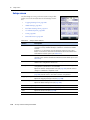
Setup screen . . . . . . . . . . . . . . . . . . .
Configuration files . . . . . . . . . . . . . . .
Choose Configuration form . . . . .
Enter Password form . . . . . . . . .
Logging Settings form . . . . . . . . . . . . .
Accuracy Settings form . . . . . . . .
Antenna Settings form . . . . . . . .
GNSS Settings . . . . . . . . . . . . . . . . . .
Using Smart Settings. . . . . . . . . .
Configuring custom GNSS settings.
NMEA Output Settings form. . . . .
RTK Precision Settings form . . . . .
Real-time Settings form . . . . . . . . . . . .
10
.
.
.
.
.
.
.
.
.
.
.
.
.
.
.
.
.
.
.
.
.
.
.
.
.
.
.
.
TerraSync Software Getting Started Guide
.
.
.
.
.
.
.
.
.
.
.
.
.
.
.
.
.
.
.
.
.
.
.
.
.
.
.
.
.
.
.
.
.
.
.
.
.
.
.
.
.
.
.
.
.
.
.
.
.
.
.
.
.
.
.
.
.
.
.
.
.
.
.
.
.
.
.
.
.
.
.
.
.
.
.
.
.
.
.
.
.
.
.
.
.
.
.
.
.
.
.
.
.
.
.
.
.
.
.
.
.
.
.
.
.
.
.
.
.
.
.
.
.
.
.
.
.
.
.
.
.
.
.
.
.
.
.
.
.
.
.
.
.
.
.
.
.
.
.
.
.
.
.
.
.
.
.
.
.
.
.
.
.
.
.
.
.
.
.
.
.
.
.
.
.
.
.
.
.
.
.
.
.
.
.
.
.
.
.
.
.
.
.
.
.
.
.
.
.
.
.
.
.
.
.
.
.
.
.
.
.
.
.
.
.
.
.
.
.
.
.
.
.
.
.
.
.
.
.
.
.
.
.
.
.
.
.
.
.
.
.
.
.
.
.
.
.
.
.
.
.
.
.
.
.
.
.
.
.
.
.
.
.
.
.
.
.
.
.
.
.
.
.
.
.
.
.
.
.
.
.
.
.
.
.
.
.
.
.
.
.
.
.
.
.
.
.
.
.
.
.
.
.
.
.
.
.
.
.
.
.
.
.
.
.
.
.
.
.
.
.
.
.
.
.
.
.
.
.
.
.
.
.
.
.
.
.
.
.
.
.
.
.
.
.
.
.
.
.
.
.
.
.
.
.
.
.
.
.
.
.
.
.
.
.
.
.
.
.
.
.
.
.
.
.
.
.
.
.
.
.
.
.
.
.
.
.
.
.
.
.
.
.
.
.
.
.
.
.
.
.
.
.
.
.
.
.
.
.
.
.
.
.
.
.
.
.
.
.
.
.
.
.
.
.
.
.196
.198
.199
.200
.200
.202
.203
.205
.205
.206
.209
.210
.211
Contents
External Source Settings form . . . . .
Receiver Port Settings form . . . . . .
Serial Port Settings form . . . . . . . .
Select Server form . . . . . . . . . . . .
Integrated Beacon Settings form . . .
Integrated OmniSTAR Settings form.
Integrated SBAS Settings form . . . .
RTK Radio Settings form . . . . . . . .
Coordinate System . . . . . . . . . . . . . . . .
Units . . . . . . . . . . . . . . . . . . . . . . . . .
External Sensors. . . . . . . . . . . . . . . . . .
Sensor Properties form . . . . . . . . .
10
.
.
.
.
.
.
.
.
.
.
.
.
.
.
.
.
.
.
.
.
.
.
.
.
.
.
.
.
.
.
.
.
.
.
.
.
.
.
.
.
.
.
.
.
.
.
.
.
.
.
.
.
.
.
.
.
.
.
.
.
.
.
.
.
.
.
.
.
.
.
.
.
.
.
.
.
.
.
.
.
.
.
.
.
.
.
.
.
.
.
.
.
.
.
.
.
.
.
.
.
.
.
.
.
.
.
.
.
.
.
.
.
.
.
.
.
.
.
.
.
.
.
.
.
.
.
.
.
.
.
.
.
.
.
.
.
.
.
.
.
.
.
.
.
.
.
.
.
.
.
.
.
.
.
.
.
.
.
.
.
.
.
.
.
.
.
.
.
.
.
.
.
.
.
.
.
.
.
.
.
.
.
.
.
.
.
.
.
.
.
.
.
.
.
.
.
.
.
.
.
.
.
.
.
.
.
.
.
.
.
.
.
.
.
.
.
.
.
.
.
.
.
.
.
.
.
.
.
.
.
.
.
.
.
.
.
.
.
.
.
.
.
.
.
.
.
.
.
.
.
.
.
.
.
.
.
.
.
.
.
.
.
.
.
.
.
.
.
.
.
.
.
.
.
.
.
.
.
.
.
.
.
.
.
.
.
.
.
.
.
.
.
.
.
.
.
.
.
.
.
.
.
.
.
.
.
.
.
.
.
.
.
.
.
.
.
.
.
.
.
.
.
.
.
.
.
.
.
.
.
.
.
.
.
.
.
.
.
.
.
.
.
.
.
.
.
.
.
.
.
.
.
.
.
.
.
.
.
.
.
.216
.220
.221
.222
.223
.224
.225
.227
.228
.230
.231
.232
High-Accuracy Data Collection . . . . . . . . . . . . . . . . . . . . . . . . 237
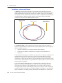
Introduction to carrier phase GNSS . . . . . . . . . . . . . . . . . . . . . . . . . . . . . . . . .
Carrier phase techniques compared . . . . . . . . . . . . . . . . . . . . . . . . . . . . . . . . .
H-Star technology . . . . . . . . . . . . . . . . . . . . . . . . . . . . . . . . . . . . . . . .
Carrier phase postprocessing . . . . . . . . . . . . . . . . . . . . . . . . . . . . . . . . .
Real-time kinematic (RTK). . . . . . . . . . . . . . . . . . . . . . . . . . . . . . . . . . .
Principles of carrier phase data collection . . . . . . . . . . . . . . . . . . . . . . . . . . . . .
Carrier lock . . . . . . . . . . . . . . . . . . . . . . . . . . . . . . . . . . . . . . . . . . . .
Initialization . . . . . . . . . . . . . . . . . . . . . . . . . . . . . . . . . . . . . . . . . . . .
Carrier blocks . . . . . . . . . . . . . . . . . . . . . . . . . . . . . . . . . . . . . . . . . . .
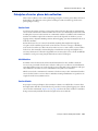
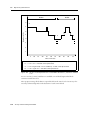
The relationship between time and accuracy . . . . . . . . . . . . . . . . . . . . . . .
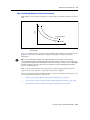
H-Star technology workflow and required infrastructure . . . . . . . . . . . . . . . . . . . .
Required infrastructure for H-Star technology . . . . . . . . . . . . . . . . . . . . . .
Configuring the TerraSync software to collect H-Star data . . . . . . . . . . . . . . .
Collecting sufficient high-accuracy data . . . . . . . . . . . . . . . . . . . . . . . . . .
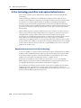
Carrier phase postprocessing workflow and required infrastructure . . . . . . . . . . . . .
Required infrastructure for carrier phase data. . . . . . . . . . . . . . . . . . . . . . .
Collecting sufficient high-accuracy data . . . . . . . . . . . . . . . . . . . . . . . . . .
Real-time kinematic workflow and required infrastructure. . . . . . . . . . . . . . . . . . .
Required infrastructure for RTK . . . . . . . . . . . . . . . . . . . . . . . . . . . . . . .
Configuring the TerraSync Centimeter edition software for RTK data collection.
Collecting sufficient high-accuracy data . . . . . . . . . . . . . . . . . . . . . . . . . .
Using corrections from a VRS network . . . . . . . . . . . . . . . . . . . . . . . . . . . . . . .
Connecting to a VRS network using an Internet connection . . . . . . . . . . . . .
Connecting to a VRS network using a direct dial connection . . . . . . . . . . . . .
A
.
.
.
.
.
.
.
.
.
.
.
.
.
.
.
.
.
.
.
.
.
.
.
.
.
.
.
.
.
.
.
.
.
.
.
.
.
.
.
.
.
.
.
.
.
.
.
.
.
.
.
.
.
.
.
.
.
.
.
.
.
.
.
.
.
.
.
.
.
.
.
.
.
.
.
.
.
.
.
.
.
.
.
.
.238
.239
.239
.239
.240
.241
.241
.241
.241
.243
.244
.244
.245
.246
.248
.248
.248
.250
.250
.250
.252
.253
.255
.261
Advanced Datalogging Options . . . . . . . . . . . . . . . . . . . . . . . 265
Data collection modes . . . . . . . . . . . . . . . . . . . .
QuickPoint Data collection mode . . . . . . . .
Log Now and Log Later data collection modes
Recording between feature positions. . . . . . . . . . .
Continuing line and area features . . . . . . . . . . . . .
.
.
.
.
.
.
.
.
.
.
.
.
.
.
.
.
.
.
.
.
.
.
.
.
.
.
.
.
.
.
.
.
.
.
.
.
.
.
.
.
.
.
.
.
.
.
.
.
.
.
.
.
.
.
.
.
.
.
.
.
.
.
.
.
.
.
.
.
.
.
.
.
.
.
.
.
.
.
.
.
.
.
.
.
.
.
.
.
.
.
.
.
.
.
.
.
.
.
.
.
.
.
.
.
.
.
.
.
.
.
.
.
.
.
.
.
.
.
.
.
.
.
.
.
.
.266
.266
.266
.267
.267
TerraSync Software Getting Started Guide
11
Contents
Offsets . . . . . . . . . . . . . . . . . . . . . . . . . . . . . . . . . . . . . . .
Complex offsets . . . . . . . . . . . . . . . . . . . . . . . . . . . . .
Recording a complex offset . . . . . . . . . . . . . . . . . . . . .
Distance-distance offset . . . . . . . . . . . . . . . . . . . . . . .
Bearing-bearing offset . . . . . . . . . . . . . . . . . . . . . . . . .
Triple bearing offset . . . . . . . . . . . . . . . . . . . . . . . . . .
Using a laser rangefinder to record offsets . . . . . . . . . . . . . . . .
Using an external sensor . . . . . . . . . . . . . . . . . . . . . . . . . . .
Repeating features . . . . . . . . . . . . . . . . . . . . . . . . . . . . . . .
Segmenting line features . . . . . . . . . . . . . . . . . . . . . . . . . . .
Recording averaged vertices . . . . . . . . . . . . . . . . . . . . . . . . .
Enhanced support for adding image files as attributes to features. .
B
.
.
.
.
.
.
.
.
.
.
.
.
.
.
.
.
.
.
.
.
.
.
.
.
.
.
.
.
.
.
.
.
.
.
.
.
.
.
.
.
.
.
.
.
.
.
.
.
.
.
.
.
.
.
.
.
.
.
.
.
.
.
.
.
.
.
.
.
.
.
.
.
.
.
.
.
.
.
.
.
.
.
.
.
.
.
.
.
.
.
.
.
.
.
.
.
.
.
.
.
.
.
.
.
.
.
.
.
.
.
.
.
.
.
.
.
.
.
.
.
.
.
.
.
.
.
.
.
.
.
.
.
.
.
.
.
.
.
.
.
.
.
.
.
.
.
.
.
.
.
.
.
.
.
.
.
.
.
.
.
.
.
.
.
.
.
.
.
.268
.270
.271
.272
.273
.273
.274
.274
.275
.275
.276
.277
.
.
.
.
.
.
.
.
.
.
.
.
.
.
.
.
.
.
.
.
.
.
.
.
.
.
.
.
.
.
.
.
.
.
.
.
.
.
.
.
.
.
.
.
.
.
.
.
.
.
.
.
.
.
.
.
.
.
.
.
.
.
.
.
.
.
.
.
.
.
.
.
.
.
.
.
.
.
.
.
.
.
.
.
.
.
.
.
.
.
.
.
.
.
.
.
.
.
.
.
.
.
.
.
.
.
.
.
.
.
.
.
.
.
.
.
.
.
.
.
.
.
.
.
.
.
.
.
.
.
.
.
.
.
.
.
.
.
.
.
.
.
.
.
.
.
.
.
.
.
.
.
.
.
.
.
.
.
.
.
.
.
.
.
.
.
.
.
.
.
.
.
.
.
.
.
.
.
.
.
.
.
.
.
.
.
.
.
.
.
.
.
.
.
.
.
.
.
.
.
.
.
.
.
.
.
.
.
.
.
.
.
.
.
.
.
.
.
.
.
.
.
.
.
.
.
.
.
.
.
.
.
.
.
.
.
.
.
.
.
.
.
.280
.280
.282
.283
.283
.285
.285
.286
.286
.287
.288
Setting up a Base Station . . . . . . . . . . . . . . . . . . . . . . . . . . . 289
Introduction . . . . . . . . . . . . . . . . . .
Logging base data to a file . . . . . . . . .
Generating real-time corrections .
Unattended base station . . . . . .
D
.
.
.
.
.
.
.
.
.
.
.
.
Coordinate Systems . . . . . . . . . . . . . . . . . . . . . . . . . . . . . . 279
Modelling the earth’s surface . . . . . . . . . . . . . . . . . . .
Geoids and ellipsoids . . . . . . . . . . . . . . . . . . .
Coordinate systems and datums . . . . . . . . . . . .
Transforming and projecting collected GNSS positions . .
Transforming real-time corrected GNSS positions .
Coordinate systems available in the TerraSync software .
Using the Coordinate System Manager utility . . . . . . . .
Transferring coordinate systems . . . . . . . . . . . . . . . .
Transferring a coordinate system export file. . . . .
Transferring a single coordinate system . . . . . . .
Configuring coordinate systems. . . . . . . . . . . . . . . . .
C
.
.
.
.
.
.
.
.
.
.
.
.
.
.
.
.
.
.
.
.
.
.
.
.
.
.
.
.
.
.
.
.
.
.
.
.
.
.
.
.
.
.
.
.
.
.
.
.
.
.
.
.
.
.
.
.
.
.
.
.
.
.
.
.
.
.
.
.
.
.
.
.
.
.
.
.
.
.
.
.
.
.
.
.
.
.
.
.
.
.
.
.
.
.
.
.
.
.
.
.
.
.
.
.
.
.
.
.
.
.
.
.
.
.
.
.
.
.
.
.
.
.
.
.
.
.
.
.
.
.
.
.
.
.
.
.
.
.
.
.
.
.
.
.
.290
.291
.291
.292
Troubleshooting . . . . . . . . . . . . . . . . . . . . . . . . . . . . . . . . 295
Communications . . . . . . . . . .
Field computer . . . . . . . . . . .
GNSS . . . . . . . . . . . . . . . . . .
Real-time differential correction.
Data files . . . . . . . . . . . . . . .
Map screen . . . . . . . . . . . . . .
Coordinate system . . . . . . . . .
Position accuracy . . . . . . . . . .
.
.
.
.
.
.
.
.
.
.
.
.
.
.
.
.
.
.
.
.
.
.
.
.
.
.
.
.
.
.
.
.
.
.
.
.
.
.
.
.
.
.
.
.
.
.
.
.
.
.
.
.
.
.
.
.
.
.
.
.
.
.
.
.
.
.
.
.
.
.
.
.
.
.
.
.
.
.
.
.
.
.
.
.
.
.
.
.
.
.
.
.
.
.
.
.
.
.
.
.
.
.
.
.
.
.
.
.
.
.
.
.
.
.
.
.
.
.
.
.
.
.
.
.
.
.
.
.
.
.
.
.
.
.
.
.
.
.
.
.
.
.
.
.
.
.
.
.
.
.
.
.
.
.
.
.
.
.
.
.
.
.
.
.
.
.
.
.
.
.
.
.
.
.
.
.
.
.
.
.
.
.
.
.
.
.
.
.
.
.
.
.
.
.
.
.
.
.
.
.
.
.
.
.
.
.
.
.
.
.
.
.
.
.
.
.
.
.
.
.
.
.
.
.
.
.
.
.
.
.
.
.
.
.
.
.
.
.
.
.
.
.
.
.
.
.
.
.
.
.
.
.
.
.
.
.
.
.
.
.
.
.
.
.
.
.
.
.
.
.
.
.
.
.
.
.
.
.
.
.
.
.
.
.
.
.
.
.
.
.
.
.
.
.
.
.
.
.
.
.
.
.
.
.
.296
.297
.298
.299
.300
.301
.302
.303
Glossary . . . . . . . . . . . . . . . . . . . . . . . . . . . . . . . . . . . . . 305
12
TerraSync Software Getting Started Guide
CHAPTER
1
Introduction
In this chapter:
Documentation conventions
About the TerraSync software
TerraSync software editions
Finding additional information
Technical assistance
1
Welcome to the TerraSync Software Getting
Started Guide. This guide provides:
•
an overview of the Trimble® TerraSync™
software
•
a guide to the user interface and general
operation of the TerraSync software
Even if you have used other Global Navigation
Satellite System (GNSS) or Global Positioning
System (GPS) products before, Trimble
recommends that you spend some time reading
this guide to learn about the special features of
this product.
This publication assumes that you know how to
use the Microsoft® Windows® operating system
that you are using.
TerraSync Software Getting Started Guide
13
1
Introduction
Documentation conventions
The documentation shows the TerraSync software as it appears on a portrait
orientation handheld, powered by the Windows Mobile® 6.5 operating system, with a
480 × 640 pixel screen. In landscape orientation, some software items are displayed
differently. However, there is no functional difference between the displays.
Landscape orientation (640 x 480)
Portrait orientation (480 x 640)
About the TerraSync software
The TerraSync software collects and updates geographical data (GIS and spatial data)
on a field computer.
Use the TerraSync software to track GNSS status, log new data and update existing
data, and navigate in the field.
The TerraSync software acts as the controlling software. It communicates with the
GNSS receiver, allowing you to set GNSS parameters in the receiver, record GNSS
positions on the field computer, and update existing GIS data.
The software can be used with a wide variety of real-time differential correction
sources. All supported GNSS receivers receive real-time correction messages from a
real-time differential correction source, allowing integrated support for Satellite Based
Augmentation Systems (SBAS) such as WAAS, EGNOS and MSAS. The SBAS
corrections are used directly by the GNSS receiver.
For externally-sourced corrections, you can use an external receiver, a radio link to an
external data radio, or use a cellphone or the handheld’s integrated modem to dial an
Internet Service Provider and then download the corrections from an Internet server.
The TerraSync software also provides mission planning in the field. Trimble office
software (the GPS Pathfinder® Office software and the Trimble GPS Analyst™
extension for Esri ArcGIS Desktop software) work with the TerraSync software. Use the
office software to create data dictionaries, transfer data, import and export files, and
postprocess collected GNSS data.
14
TerraSync Software Getting Started Guide
1
Introduction
TerraSync software editions
The TerraSync software is available in three editions: Standard, Professional, and
Centimeter. The TerraSync Professional and Centimeter editions offer several
additional useful features; you can:
•
update imported data files, including:
–
SSF files transferred from TerraSync Standard edition software using the
Trimble Data Transfer utility.
–
data files created from Shapefiles.
–
data files received by email.
•
display background images or data files in the Map section.
•
use an external sensor (including laser rangefinders) when collecting data.
With the Centimeter edition you can also use a survey receiver to collect RTK data.
If you have purchased the TerraSync Standard edition software and would like to use
the additional functions provided in the Professional edition, you can upgrade your
software to the TerraSync Professional edition software.
If you have purchased the TerraSync Professional edition software and would like to
collect RTK data, you can updgrade to the TerraSync Centimeter edition. You cannot
upgrade directly from the Standard edition to the Centimeter edition. For upgrade
pricing details, contact your local Trimble reseller.
This manual describes the TerraSync Centimeter edition software. If a feature or
option it describes is not available in the TerraSync Standard or Professional edition
software, this is indicated with a note at the beginning of the relevant section.
The TerraSync software user interface can also be customized using the TerraSync
Studio in the GPS Pathfinder Office software. This means that some sections or options
in the TerraSync software can be hidden from the user. If a section or option described
in this manual can be hidden from the user, this is indicated with a note at the
beginning of the relevant section.
Finding additional information
In addition to the TerraSync Software Getting Started Guide (this document), TerraSync
Software Release Notes are also available. The TerraSync Software Release Notes describe
new features in this version of the software and any changes to the documentation,
and provide any information not included in the product documentation. The release
notes are available as a download from the TerraSync software technical support page
(www.trimble.com/mappingGIS/terrasync).
TerraSync Software Getting Started Guide
15
1
Introduction
Technical assistance
If you have a problem and cannot find the information you need in the product
documentation, contact your Trimble reseller.
Technical support
Go to the TerraSync software technical support page
(www.trimble.com/terrasync_ts.asp) for the latest support information about the
software, including:
•
Support notes detailing the latest support issues
•
Documentation
•
The latest files available for download
Windows error reporting
If a Microsoft Windows Error Reporting dialog appears, indicating that the TerraSync
software has encountered a problem and needs to close, you are asked whether you
wish to send an error report to Microsoft.
Trimble recommends that you click Send and then click any subsequent links that are
used to obtain additional information.
Trimble can access the report that is sent to Microsoft and use it to improve the
TerraSync software.
16
TerraSync Software Getting Started Guide
CHAPTER
2
Software Installation and Activation
In this chapter:
System requirements
Registering the TerraSync
software
Installing the TerraSync software
Activating the TerraSync software
Updating the TerraSync software
Installing a translation of the
TerraSync software
Compatible GNSS receivers
2
This chapter describes how to install and
activate the TerraSync software on a handheld
device powered by the Windows Mobile
operating system, or onto an office computer
that is running a Windows operating system.
To install and run the TerraSync software, you
must:
1.
Make sure your handheld or office
computer meets the minimum platform
requirements for successful operation of
the TerraSync software.
2.
Register the Proof-of-Purchase Number
(POPN) that you received when you
purchased the TerraSync software, and
obtain an installation code.
3.
Download the software, and install it using
the installation code you obtained when
you registered your POPN.
4.
Activate the software on the office
computer, and on the handheld device
depending on the operating system.
TerraSync Software Getting Started Guide
17
2
Software Installation and Activation
System requirements
Computer specifications
The TerraSync software runs on handheld devices powered by the Windows Mobile
5.0, 6, 6.1, and 6.5 operating systems.
The TerraSync software runs on computers running any of the following Microsoft
operating systems, including 64-bit variants:
•
Windows 7 (Ultimate Edition, Professional Edition, or Home Premium Edition
SP1)
•
Windows Vista® (Ultimate Edition, Enterprise Edition, Business Edition, or
Home Premium Edition SP2)
•
Windows XP (Professional Edition, or Tablet PC Edition SP3).
Required software
To install the TerraSync software onto a device powered by the Windows Mobile
operating system and to transfer files between a desktop computer and a Windows
Mobile powered device, you must have the appropriate Microsoft software installed on
your computer or Tablet PC. The software you use to manage the connection between
the device and the computer depends on the operating system the office computer is
running. If the computer is running:
•
Windows Vista® or Windows 7, make sure you have downloaded and installed
the Windows Mobile Device Center.
•
Windows XP, make sure you have installed the appropriate version of Microsoft
ActiveSync® technology.
For more information, see Step 1: Install Microsoft connection management software
onto the computer, page 25.
To transfer files between a desktop computer and a field computer running the
TerraSync software, you must also have one of the following installed on the desktop
computer:
18
•
the Trimble Data Transfer utility, which is available to download from
www.trimble.com/datatransfer.shtml
•
the Trimble GPS Pathfinder Office software, version 5.10 or later
TerraSync Software Getting Started Guide
2
Software Installation and Activation
Registering the TerraSync software
Before you can install the TerraSync software, you must register the POPN that you
received when you purchased the software. You will then receive an installation code
that you enter during the installation process.
You can only register your POPN once. For information about obtaining your
installation code when your POPN has previously been registered, see Obtaining your
installation code after registration, page 23.
Trimble recommends that you register before beginning installation.
To register, you need:
•
the Proof-of-Purchase Number (POPN) from the POPN certificate that you
received by email or from your Trimble reseller when you purchased the
TerraSync software
•
Internet access (including a valid email address)
Note – If you do not have Internet access, contact your local Trimble reseller for assistance.
To register your POPN for the TerraSync software:
1.
Go to the My Trimble account login page.
To do this, open your Web browser and go to www.trimble.com/register.
Your default Web browser opens and displays the My Trimble account login
page:
2.
If you already have an account, skip this step and go to step 3 to log in.
To create your My Trimble account, click Create an account. Enter your contact
details and then click Save. Your account is created and you are returned to the
My Trimble account login page.
3.
Enter your email address and password, and then click Login.
TerraSync Software Getting Started Guide
19
2
Software Installation and Activation
The My Trimble page for your account appears. It will look similar to the one
shown below:
4.
To register your POPN for the TerraSync software, scroll to the My Products
section and then click Add.
The Registration Method page appears:
20
TerraSync Software Getting Started Guide
2
Software Installation and Activation
5.
Select the Add a Proof-of-Purchase Number (POPN) option and then click Next.
The Proof-of-Purchase Number (POPN) Details page appears:
6.
Enter the POPN that you received on the POPN certificate when you purchased
the software.
7.
If you want to enter your own reference code, for example a sales order number
or an asset/inventory number, enter it in the Your Reference field.
8.
Click Next.
Note – If a message warns that the POPN you entered has already been registered, click
Cancel to cancel the registration process. Then obtain the installation code for your POPN
and install the software. For more information, see Obtaining your installation code after
registration, page 23.
9.
If this is the first time that you have registered a Trimble Mapping and GIS
product, the Mapping & GIS Industry Details page appears. From the drop-down
lists, select your organization type and most common market segment and then
click Save.
TerraSync Software Getting Started Guide
21
2
Software Installation and Activation
You are returned to your My Trimble page, where the software you have just
registered now appears in the My Products section:
Installation
code
10. If the five lines below the TerraSync software do not appear, click the + beside
the TerraSync software that you have just registered.
The Installation Code field shows the installation code for the POPN you
received when you purchased the TerraSync software. Make a note of this code.
You must enter this code when you install or reinstall the software.
Note – If you are entitled to an upgrade from a previous version of the TerraSync software,
you can install a later version of the TerraSync software using the installation code that
you obtained when you first registered the product. If you are not entitled to an upgrade,
the installation program will not accept your installation code. Contact your local Trimble
reseller to purchase a software maintenance option.
22
TerraSync Software Getting Started Guide
2
Software Installation and Activation
Obtaining your installation code after registration
To reinstall the TerraSync software, for example if you performed a factory reset on the
device or reinstalled the operating system, you must use the same installation code
that you received when you registered the software before installing it for the first time.
If you do not know the installation code, do one of the following:
•
If someone else at your company registered the POPN for the software, ask them
for the installation code.
If you cannot find out who registered the software, contact your local Trimble
reseller.
•
If you registered your POPN for the software yourself, you can check your
installation code from the My Trimble page of the Trimble website.
To do this:
a.
Open your Web browser and go to www.trimble.com/register.
Your default Web browser opens and displays the My Trimble account login
page:
b.
Enter your email address and password and then click Login.
The My Trimble page for your account appears.
TerraSync Software Getting Started Guide
23
2
Software Installation and Activation
c.
Scroll to the My Products section, where any software that you have already
registered appears:
d.
If the five lines below the TerraSync software do not appear, click the +
beside the TerraSync software that you have just registered.
Installation
code
The Installation Code field shows the installation code for your POPN for
the TerraSync software. Make a note of this code. You need to enter this
code when you install or reinstall the software. You can also check which
device the registered Installation Code has been activated on.
24
TerraSync Software Getting Started Guide
2
Software Installation and Activation
Installing the TerraSync software
This section describes how to install the TerraSync software onto a handheld device
powered by the Windows Mobile operating system, and onto an office computer
running the Windows operating system.
Installing the TerraSync software onto a handheld device
The installation procedure comprises the following steps:
1.
Install Microsoft connection management software onto the office computer.
2.
Connect the Windows Mobile powered device to the office computer.
3.
Back up any TerraSync software data files.
4.
Uninstall any previously installed versions of the TerraSync software.
5.
Check that you have enough space on the device to install the TerraSync
software.
6.
Install the required version of the TerraSync software.
More information about each step is provided below.
Step 1: Install Microsoft connection management software onto the
computer
Note – You must install the Windows Mobile Device Center or ActiveSync technology onto
the computer before you connect the device.
To install software onto a Windows Mobile powered device, you must connect the
device to the office computer. If the computer is running:
•
the Windows Vista or Windows 7 operating system, use the Windows Mobile
Device Center to manage the connection.
•
the Windows XP operating system, use Microsoft ActiveSync technology to
manage the connection.
Installing the Windows Mobile Device Center
The Windows Vista and Windows 7 operating systems include a basic connectivity
driver for Windows Mobile powered devices. This driver allows you to transfer files
from the device to your computer.
To install software onto a Windows Mobile powered device, or to use the more
advanced desktop synchronization features with your device, you must install
Windows Mobile Device Center 6 onto your office computer.
You can download the Windows Mobile Device Center from
www.microsoft.com/windowsmobile/devicecenter.mspx.
TerraSync Software Getting Started Guide
25
2
Software Installation and Activation
Installing ActiveSync technology
ActiveSync technology may be supplied on a CD with the Windows Mobile powered
device, or you can download it from www.microsoft.com/windowsmobile.
B
Tip – If you are installing a translation of the TerraSync software and you want all
installation screens to appear in the translated language, install the corresponding
translation of the ActiveSync technology. You can download translated versions of the
ActiveSync technology from the Microsoft website.
Step 2: Connect the device to an office computer
1.
Make sure that the device and the computer are turned on.
2.
Connect the device to the office computer using either a USB cable connection
or Bluetooth® wireless technology. For more information on connecting the
device to a computer, refer to the documentation for the Windows Mobile
powered device.
When the device is connected, a window appears on the office computer that
enables you to manage the connection.
3.
If the office computer is running:
•
the Windows Vista or Windows 7 operating system:
a.
If the Autoplay window appears, close the window.
b.
The Windows Mobile Device Center window displays the message
Connected:
c.
Click Connect without setting up your device.
d.
Use the Windows Mobile Device Center to back up data files and uninstall
any previous versions of the software (see Step 3, page 28 and Step 4,
page 28).
For more information, refer to the Windows Mobile Device Center Help.
26
TerraSync Software Getting Started Guide
Software Installation and Activation
•
2
the Windows XP operating system:
a.
If the Synchronization Setup Wizard appears, click Cancel to close the
wizard:
b.
The Microsoft ActiveSync window displays the message Connected:
c.
Use ActiveSync technology to back up data files and uninstall any previous
versions of the software (see Step 3 and Step 4 below).
For more information, refer to the ActiveSync Help.
TerraSync Software Getting Started Guide
27
2
Software Installation and Activation
Step 3: Back up any TerraSync software data files
Before installing a new version of the TerraSync software, Trimble recommends that
you transfer any existing TerraSync software data files to the office computer.
To transfer files using...
do the following...
the Windows Mobile Device Center
click File Management and use the Windows
Explorer-type window to copy files.
ActiveSync technology
click Explore and use the Windows Explorertype window to copy files.
Step 4: Uninstall any previous versions of TerraSync software
Before installing a new version of the TerraSync software, Trimble recommends that
you uninstall any previously installed versions of the TerraSync software from the
Windows Mobile powered device and the office computer.
To remove programs...
do the following:
from the device using the Windows Mobile click Programs and Services and then click
Device Center
Add/Remove Programs.
B
Tip – If the Add/Remove Programs option
is not displayed below Programs and
Services, click More. The Add/Remove
Programs option appears.
from the device using ActiveSync
technology
select Add/Remove Programs from the Tools
menu.
from the office computer
use the Add or Remove Programs tool in the
Control Panel.
Step 5: Check that you have enough space on the device
Before you install the TerraSync software, make sure that you have enough free space
on the device. The TerraSync software requires at least 18 MB of free space. If you are
installing it to a secondary internal storage location, the TerraSync software requires at
least 18 MB of free space in that location, plus 5 MB of RAM.
Note – The installation program cannot determine how much memory is available in the
non-volatile storage location. You must ensure that 18 MB is free before you begin the
installation.
If there is not enough memory space on the device, a message appears during
installation, indicating the amount of memory left on the device.
Click Cancel, remove any unwanted programs or data files from the device, and/or
increase storage memory. Then start the installation again.
28
TerraSync Software Getting Started Guide
Software Installation and Activation
2
If memory space in the secondary internal storage location is insufficient, the
installation may appear to complete successfully, but error messages may appear when
you try to run the TerraSync software. If this happens, make more space available in the
secondary storage location and then install the software again.
Step 6: Install the TerraSync software onto the device
1.
2.
Before you begin, make sure that:
–
you have registered the POPN that you received when you purchased the
software, and have made a note of the installation code that you must enter
during installation. For more information, see Registering the TerraSync
software, page 19.
–
the TerraSync software is not running on the device.
–
you have closed all applications on the device.
www.trimble.com/terrasync_ts.asp. Click Downloads and then click the
required version of the software.
The InstallShield Wizard launches.
On the Welcome screen, click Next:
3.
Read the software license agreement, select I accept the terms of the license
agreement and then click Next.
4.
The Register your Software page appears. Do one of the following:
–
If you have registered the software and obtained your installation code for
the software, select the I have already registered option and then click Next.
–
If you have not yet registered the software and do not have an installation
code for the software, select the I do not have an installation code. I want to
register my POPN over the Internet now option and then click Next.
TerraSync Software Getting Started Guide
29
2
Software Installation and Activation
The Register page opens in your default Web browser, displaying the My
Trimble account log in. For more information, see Registering the
TerraSync software, page 19.
The Enter your Installation Code page appears:
5.
Enter the installation code that you received when you registered the POPN for
the TerraSync software and then click Next.
6.
The Start Copying Files page appears. Click Next.
7.
If prompted, Install “Trimble TerraSync” using the default application install directory?,
click Yes.
Note – If an SD (Secure Digital) memory card is inserted in the handheld, the card
appears as an installation location option. Trimble recommends that you install software
to the handheld's internal storage, not to an SD memory card. If you install software to a
card and then remove the card from the handheld, the software will not be available for
use.
8.
If you clicked No in Step 7, the Select Destination Media dialog appears. Click OK
to proceed with the installation.
On some Windows Mobile powered devices, such as the Trimble Recon®
handheld, the message Adding information for “Remove Programs” may remain on
the screen for several minutes. Do not cancel the installation or reset the device
while this message is displayed.
9.
Check your mobile device screen to see if any additional steps are necessary to
complete the installation
10. On the InstallShield Wizard Complete screen, click Finish.
30
TerraSync Software Getting Started Guide
2
Software Installation and Activation
Installing the TerraSync software onto an office computer running a
Windows operating system
This section describes how to install the TerraSync software onto an office computer,
such as a laptop or a Tablet PC, that is running a Windows operating system.
The installation procedure comprises the following steps:
1.
Back up any TerraSync software data files.
2.
Uninstall any previously installed versions of the TerraSync software.
3.
Install the TerraSync software.
More information about each step is provided below.
Step 1: Back up any TerraSync software data files
Before installing a new version of the TerraSync software, Trimble recommends that
you transfer any TerraSync software data files to a safe storage location.
Step 2: Uninstall any previous versions of TerraSync software
Before installing a new version of the TerraSync software, Trimble recommends that
you uninstall any previously installed versions of the TerraSync software.
Step 3: Install the TerraSync software onto the computer
1.
2.
Before you begin, make sure that:
–
you have registered the POPN that you received when you purchased the
software, and have made a note of the installation code that you must enter
during installation. For more information, see Registering the TerraSync
software, page 19.
–
the TerraSync software is not running on the computer.
–
you have closed all open windows programs on the office computer.
Go to www.trimble.com/terrasync_ts.asp. Click Downloads and then click the
version you want to install.
TerraSync Software Getting Started Guide
31
2
Software Installation and Activation
The InstallShield Wizard launches. On the Welcome screen, click Next:
3.
Read the software license agreement, select I accept the terms of the license
agreement and then click Next.
The Register your Software page appears:
4.
Do one of the following:
–
If you have registered the software and obtained your installation code for
the software, select the I have already registered option and then click Next.
–
If you have not yet registered the software and do not have an installation
code for the software, select the I do not have an installation code. I want to
register my copy over the Internet now option and then click Next.
The Register page opens in your default Web browser, displaying the My
Trimble account log in. For more information, see Registering the
TerraSync software, page 19.
32
TerraSync Software Getting Started Guide
2
Software Installation and Activation
The Enter your Installation Code page appears:
5.
Enter the installation code that you received when you registered the POPN for
the TerraSync software and then click Next.
6.
In the Choose Desktop Software Location page, select the folder where the setup
will install the program files and then click Next.
7.
The Start Copying Files page appears. Click Next.
8.
The final page of the installation wizard shows InstallShield Wizard Complete.
Click Finish.
Activating the TerraSync software
The TerraSync software must be activated once it is installed.
1.
If not already started by the installation process, start the Activation Wizard.
Click Start / All Programs / Trimble / TerraSync x.x WM / Trimble TerraSync
Activator. The Activation Wizard was installed on your office computer during
the TerraSync software installation.
Note – The Activation Wizard is a .NET framework application. If your office computer is
running the Windows XP or Windows Vista operating system, you must also have the
latest Service Packs installed.
2.
Select your preferred language.
The Activation Wizard connects to the field computer through the Microsoft
ActiveSync technology or the Windows Mobile Device Center.
TerraSync Software Getting Started Guide
33
2
Software Installation and Activation
3.
Select an activation method:
Select this method
If...
See...
I wish to activate the Trimble TerraSync
software over the Internet
Your office computer is connected to the Internet.
Trimble recommends this method.
page 35
I already have a Trimble TerraSync software
Activation Key for this device
If your Trimble Reseller has provided you with an
Activation Key, or you have previously activated this
Installation Code on the same field computer and
kept a record of the Activation Key.
page 35
I do not have an Internet connection
You do not have an Internet connection.
page 37
Product information
The Wizard will now extract information about the connected device that will help
you identify it at a later stage.
34
TerraSync Software Getting Started Guide
2
Software Installation and Activation
You will be able to edit the Device Name to customize it to your environment.
Depending on the connected device type, you may also be required to enter the device
serial number.
Online activation
The Wizard communicates directly with the Trimble Activation server and activates
the TerraSync software on your field computer:
Activation using an existing Activation Key
The Activation Wizard prompts you for the folder where the Activation Key is stored.
This could be on a local or network drive, or an external memory card, such as a USB
memory stick or SD card:
TerraSync Software Getting Started Guide
35
2
Software Installation and Activation
Use the Browse button to navigate to the required folder:
If the Activation Wizard cannot find an Activation Key for the connected device in the
selected folder, it will continue to prompt for a different folder.
Activation succeeds only if the Activation Key matches the connected field computer:
36
TerraSync Software Getting Started Guide
2
Software Installation and Activation
Offline activation
1.
Print out or write down the information that appears:
2.
Send the information to your Trimble reseller.
Your Trimble reseller will return the Activation Key on an electronic media
(diskette, CD, SD card, or USB memory stick).
3.
Insert the media into the office computer that is connected to the field
computer.
4.
Follow the steps as described above for Activation using an existing Activation
Key.
TerraSync Software Getting Started Guide
37
2
Software Installation and Activation
Activation troubleshooting
One of the following issues may occur:
•
No valid Installation Code:
•
The Installation Code is assigned to another device:
In these circumstances, enter a valid or previously unused Installation Code. If in
doubt, contact your Trimble reseller.
38
TerraSync Software Getting Started Guide
Software Installation and Activation
2
Starting the TerraSync software
The TerraSync software will run only when you have successfully activated the
software. If a valid Activation Key is not found, the following error message appears:
Tap ok to exit and then run the Activation Wizard to activate the software, see page 33.
TerraSync Software Getting Started Guide
39
2
Software Installation and Activation
Updating the TerraSync software
The TerraSync support page www.trimble.com/mappingGIS/terrasync on the Trimble
website has the latest software and language updates.
Installing a translation of the TerraSync software
Trimble recommends that you install a translation of the TerraSync software only on a
Windows Mobile device that has the corresponding language version of the operating
system installed. For example, install the Japanese TerraSync software on a device that
has been provisioned as a Japanese Windows operating system.
Note – The Regional Options applet in the Control Panel changes only the display of date,
time, units, and currency information. It does not change the language of the operating
system running on the device or field computer.
System commands (such as the Done / OK and Cancel buttons) are generated by the
operating system, so they appear in the language of the operating system on the field
computer. If you use the TerraSync software on a field computer that does not have the
corresponding translation of the operating system installed, system commands are not
translated. Also, some characters may not be interpreted or displayed correctly.
For best results, make sure that the languages used by the TerraSync software and the
operating system match.
The TerraSync software is available in several languages.
To install a translation of the TerraSync software:
1.
On the TerraSync support page (http://www.trimble.com/terrasync_ts.asp), go
to the Downloads section and click the required version of the software.
2.
Select TerraSync Software Language Files.
3.
Select the required operating system option ( for installation on a Windows
Mobile powered device, or an office computer)
4.
Select the required language file, and save it to your office computer.
Run the file to complete the installation.
Install fonts onto the Windows Mobile powered device
When you install a translation of the TerraSync software on a Windows Mobile
powered device, you must also install a TerraSync language font if both of the following
are true:
•
40
You have installed the TerraSync software in one of the following languages:
–
Chinese
–
Japanese
TerraSync Software Getting Started Guide
2
Software Installation and Activation
–
•
Korean
The language version of the operating system does not match the language of
the TerraSync software ( for example, if you have installed the Japanese
TerraSync software onto an English Windows Mobile powered device)
C
CAUTION – Do not install the Japanese font onto a Windows Mobile powered device
with the Japanese version of the operating system installed. This can cause software
errors on the device.
B
Tip – If you see squares or unusual characters instead of characters from the appropriate
language, you need to install a font.
Chinese, Japanese, Korean, or Russian TerraSync software on an English (or other
foreign) Windows Mobile powered device does not recognize Asian or Cyrillic
characters entered using a keyboard. This is because the English device cannot
convert the Unicode characters to multi-byte characters. However, Japanese TerraSync
software running on a Japanese Windows Mobile powered device recognizes Japanese
characters correctly.
Cyrillic characters, from data dictionaries created in the GPS Pathfinder Office
software using Russian Windows, are not displayed correctly in Russian TerraSync
software. However, this text displays correctly when transferred back to the GPS
Pathfinder Office software. Data dictionaries created in the GPS Pathfinder Office
software using Chinese, Japanese, or Korean Windows are displayed properly.
B
Tip – The Trimble GPS Pathfinder font is installed automatically when you install the
TerraSync software. This font includes symbols that you can use to represent point
features on the map. If you want to use other symbol fonts for point features, install the
additional fonts manually.
To install a TerraSync language font onto a Windows Mobile powered device:
1.
C
Uninstall any previous versions of the font.
CAUTION – On some Windows Mobile powered devices, you cannot delete Asian
language fonts in the usual way. To remove such fonts, you may need to perform a hard
reset of the device. A hard reset removes all software that is not pre-installed on the
device by the manufacturer.
2.
Make sure that you have enough free memory to install the font. TerraSync
language fonts require 9 to 10 MB of free memory.
3.
go to www.trimble.com/terrasync_ts.asp. Click Downloads and then click the
required version of the software.
4.
Select TerraSync Software Language Files.
5.
Select TerraSync Asian Font File.
6.
Select the option for the language that you require.
7.
Follow the instructions on the screen to install the font.
TerraSync Software Getting Started Guide
41
2
Software Installation and Activation
Note – TerraSync fonts should always be installed to RAM (main memory). Do not install
fonts to a secondary internal storage location or to a removable storage device.
8.
When the installation is complete, perform a soft reset of the device.
For information how to perform a soft reset, refer to the documentation for the device.
Compatible GNSS receivers
The TerraSync software will connect to all supported receivers as listed in the Product
Compatibility List.
Connecting to a receiver
You can connect the receiver to a port on the field computer using one of the options
described below.
Port
Connection method
Bluetooth port
Use the Bluetooth management software provided with your field
computer and the receiver to configure and then establish the
Bluetooth wireless connection.
Standard RS-232 serial
(COM) port
Connect the receiver cable to the curly straight-through cable.
Trimble recommends that you use the cable with P/N 45052 to
protect the field computer from power supplied by the receiver.
Connect the curly straight-through cable to the field computer.
Customized serial (COM)
port
Connect the receiver cable to the null modem adaptor
(P/N 43197). The adaptor changes gender, and also protects the
field computer from power supplied by the receiver. Connect the
null modem adaptor to the data download cable that was
supplied with the field computer. Connect the data download
cable to the field computer.
CompactFlash serial port
Connect a CompactFlash serial adaptor to the CompactFlash port.
Then connect as for a standard COM port.
Note – A field computer uses more power when a receiver is
connected to its CompactFlash serial port. This type of connection
will discharge the battery in the field computer more quickly.
Note – To use GNSS positions from the integrated receiver when the TerraSync software is
installed on a GeoExplorer series handheld, configure the TerraSync software to connect to
GNSS on COM3.
Powered connections
C
42
CAUTION – Using COM port cabling that supplies power to the field computer can cause
problems with, or even permanent damage to, the field computer. Some receivers supply
power, and some cables transfer power through one or more of their pins. Trimble
strongly recommends that you protect the field computer by connecting either the null
TerraSync Software Getting Started Guide
2
Software Installation and Activation
modem adaptor (P/N 43197) or the curly straight-through cable (P/N 45052) to the
receiver cable. These two connectors do not supply power, so they will protect the field
computer from power output by the receiver.
If a powered connection is acceptable or necessary, you can connect directly to the
receiver, or you can use the curly straight-through cable P/N 30236 instead of cable
P/N 45052. If you are unsure whether a powered connection will cause damage, refer to
the user manual for the field computer or consult the manufacturer before using
P/N 30236.
Connecting to external real-time correction devices
To connect to a receiver and an external real-time correction device such as a Trimble
GeoBeacon™ receiver, use one of the following options:
•
If you are using a serial cable connection to both receivers, use a splitter cable.
•
If the field computer has two Bluetooth ports, you can connect to both the
receiver and the real-time correction device using Bluetooth connections.
•
If the field computer has only one Bluetooth port, use Bluetooth wireless
technology to connect the real-time correction device to the receiver and then
use Bluetooth wireless technology to connect the receiver to the field computer.
Alternatively you can use a combination of Bluetooth wireless technology and
cabling.
For more information, refer to the documentation provided with the receiver and the
real-time correction device.
TerraSync Software Getting Started Guide
43
2
44
Software Installation and Activation
TerraSync Software Getting Started Guide
CHAPTER
3
User Interface and Data Entry
In this chapter:
Using the Windows operating
system
Using the Windows Mobile
operating system
Starting and exiting the TerraSync
software
Section structure
The TerraSync software display
Interacting with the TerraSync
software
3
This chapter contains detailed information about
the TerraSync software user interface and data
entry methods.
TerraSync Software Getting Started Guide
45
3
User Interface and Data Entry
Using the Windows operating system
You can install the TerraSync software on an office computer (desktop, laptop, or
Tablet PC), instead of on a Windows Mobile powered device.
This manual describes the TerraSync software as it appears on a portrait orientation
handheld, powered by the Windows Mobile 6.5 operating system, with a 480 × 640 pixel
screen (see Documentation conventions, page 14). On an office computer, some
software items appear differently. The main difference is that on a larger screen the
TerraSync software display is arranged in panes, so you can view up to three sections at
the same time (see Panes, page 76).
Except where specified, any information in this manual that relates to the operation of
the TerraSync software on a Windows Mobile powered device also applies to its
operation on an office computer.
Using the Windows Mobile operating system
This manual assumes that you are reasonably familiar with the Microsoft Windows
Mobile operating system that you are using.
For information about some Windows Mobile operating system features that are useful
when using the TerraSync software, see:
•
Adjusting the backlight, page 46
•
Working with other applications, page 46
•
Using the on-screen keyboard, page 47
•
Device Lock utility, page 47
Adjusting the backlight
You can change the backlight brightness on any device powered by a Windows Mobile
operating system, to adjust to indoor or outdoor operation. For information on
changing device settings, refer to the documentation for the device.
Working with other applications
The Windows Mobile operating system is similar to a desktop Windows operating
system. You can use the same methods on the device as you would on a Windows
computer to start, exit, or switch between programs. For example, to switch from the
active application to another application, tap the program icon in the taskbar.
Alternatively, if the device has a keyboard, you can use the [Alt] + [Tab] key combination.
Some programs on a Windows Mobile powered device do not have a close button or a
menu command for exiting the program. Instead, you must use system software to
shut down a particular program. If the device does not have a keyboard, you must also
use system software to switch from the active application to another application.
46
TerraSync Software Getting Started Guide
3
User Interface and Data Entry
To shut down or switch to a task that is running on a Windows Mobile powered device:
1.
On the Windows Mobile taskbar, tap
/Task Manager.
2.
Do one of the following:
•
To end a task, select the the task you want to end
and then tap End Task.
•
To switch to another task, select the task you want
to switch to and then tap Menu / Switch To.
3.
Tap
to close the Task Manager dialog.
When the TerraSync software is already running on a
device, tapping
/ Programs / TerraSync does not start
the software a second time. Instead, the TerraSync
software becomes the active program. Use this method
to switch back to the TerraSync software from another
application.
B
Tip – Some devices have hardware buttons that start specific applications. You may be
able to change the program that is assigned to a particular button, or you can delete the
existing program assignment so that pressing the button has no effect. Removing or
changing hardware button assignments can be helpful if you frequently activate
hardware buttons by accident.
Using the on-screen keyboard
For devices that do not have a physical keyboard, enter text using the on-screen
keyboard. To activate the on-screen keyboard, tap the keyboard button in the taskbar.
The on-screen keyboard pops up and partially covers any screen that is open. When
you have finished entering text in a field, tap Enter to accept the text you have entered
and move to the next field. To hide the on-screen keyboard, tap the keyboard button
on the taskbar again.
The on-screen keyboard consists of rows of alphabetic or alphanumeric keys, laid out
like a real keyboard. As you tap each key, the corresponding character is added to the
current text or numeric field in the current program.
Device Lock utility
The Device Lock lets you lock the device so that accidentally pressing the screen, keys,
or hardware buttons has no effect. Locking the device lets you safely clean the screen
or exterior of the device, transport it, or carry it.
Tap the Device Lock icon
on the Start screen to lock the screen and keypad while
the handheld remains turned on.
Once the handheld is locked, the screen and most of the keys do not respond until the
handheld is unlocked. The exceptions are the Power key and the Reset button, which
always respond when pressed.
TerraSync Software Getting Started Guide
47
3
User Interface and Data Entry
Communication with external devices such as a GNSS receiver, or external sensors
used by the TerraSync software, is not interrupted by locking the device. This means
that you can keep using the TerraSync software when the device is locked. For
example, you could lock the device so that you can safely transport it in your pocket
between features, but keep the TerraSync software connected to the GNSS receiver so
that you can collect a continuous block of carrier phase data.
When the device is locked, the lock screen shows, providing
multiple unlock sliders for different applications ( for example, if a
new email has arrived, an email unlock slider takes you straight
to the email.) To unlock the device and continue using the
TerraSync software, slide the Unlock icon for the software.
Starting and exiting the TerraSync software
To start the TerraSync software on a Windows Mobile powered device, do one of the
following:
•
On the Home screen, tap the handheld / GNSS
receiver item, and then tap GNSS Application
launcher or tap GNSS on the tile bar.
•
Tap
/TerraSync.
While the software is loading, a Trimble identification
screen appears. The software always opens at the Skyplot
subsection of the Status section.
To exit and close the TerraSync software, tap the dropdown arrow on the Section menu, and then select Exit.
Tap Yes to confirm.
To minimise the TerraSync software and keep it running, tap
screen.
48
TerraSync Software Getting Started Guide
on any TerraSync
3
User Interface and Data Entry
To switch to the TerraSync software when it is already running, do one of the following:
•
Use any of the methods described above for starting the TerraSync software.
•
On a Windows office computer, click the TerraSync button on the taskbar.
Section structure
The TerraSync software is arranged in five sections:
Note – Some sections or options in the TerraSync software may have been hidden using the
TerraSync Studio utility in the GPS Pathfinder Office software.
Section
Map
Function
View features, background files, and the GNSS trail graphically.
Note – Some options in the Map section may be hidden. This
customization is done using the TerraSync Studio utility in the GPS
Pathfinder Office software.
Data
Work with data files:
• create a new data file or open an existing data file
• collect new features or maintain existing features
• move, copy, delete, or rename data and background files
Note – Some options in the Data section may be hidden. This
customization is done using the TerraSync Studio utility in the GPS
Pathfinder Office software.
Navigation
Navigate to features using the Direction Dial and Close-up screen.
Create and edit waypoints.
Note – The Navigation section, and all navigation options, may be
hidden. This customization is done using the TerraSync Studio utility in
the GPS Pathfinder Office software.
Status
View information about:
• the satellites the TerraSync software is tracking, their relative
positions in the sky, and your current position
• the GNSS receiver and real-time correction source
• the TerraSync software version and trademark information
Note – Some options in the Status section may be hidden. This
customization is done using the TerraSync Studio utility in the GPS
Pathfinder Office software.
Setup
Configure the TerraSync software.
Note – The Setup section may be hidden. This customization is done
using the TerraSync Studio utility in the GPS Pathfinder Office software.
TerraSync Software Getting Started Guide
49
3
User Interface and Data Entry
The TerraSync software display
The screen below shows elements that are common to all screens in the TerraSync
software:
Section button
Subsection button
Form title
Field label
Status bar
Buttons
Field value
Buttons
Status bar
The status bar appears at the top of the TerraSync software screen and provides basic
status information about the connected GNSS receiver. For information about how to
connect to a receiver, see Connecting to a receiver, page 42.
Satellite icon
Logging icon
Real-time correction
source icon
Estimated
accuracy icon
Battery icon
Filter icon
The status bar is always visible, but the icons displayed depend on the current status of
the system. Table 3.1 shows the icons that can appear.
Table 3.1
Icon
50
Status bar: Icons
Name
Description
Satellite icon
Shows whether the geometry of the satellites is good or bad, as configured in
the GNSS settings area of the software. The satellite icon flashes when the
geometry of the satellites (their PDOP or HDOP) is poor.
The number next to the icon indicates how many satellites are being used to
compute GNSS positions. The number flashes when not enough satellites are
available. You need at least four satellites to compute GNSS positions.
Connect icon
When the TerraSync software is trying to connect to a receiver, the connect icon
appears instead of the satellite icon. If the TerraSync software cannot connect to
the GNSS receiver, the connect icon flashes.
TerraSync Software Getting Started Guide
User Interface and Data Entry
Table 3.1
Icon
3
Status bar: Icons (continued)
Name
Description
Antenna icon
If the TerraSync software connects to the receiver but cannot find a GNSS
antenna, the antenna icon appears instead of the satellite icon. This icon flashes
to warn you that there is a problem.
If no icon appears in this position, no GNSS receiver is connected.
Real-time
external icon
Shows that the TerraSync software is receiving real-time corrections from an
external source, such as a radio.
Integrated RTK
radio icon
Shows that the TerraSync Centimeter edition software is receiving RTK
corrections through the GNSS receiver’s integrated radio.
External RTK
icon
Shows that the TerraSync Centimeter edition software is receiving RTK
corrections through an external radio.
Real-time
external beacon
icon
Shows that the TerraSync software is receiving real-time corrections from an
external beacon receiver such as a GeoBeacon receiver.
Real-time
beacon icon
Shows that the TerraSync software is receiving real-time corrections from a
beacon.
Real-time
satellite icon
Shows that the TerraSync software is receiving real-time corrections from a
satellite differential service.
Real-time SBAS
icon
Shows that the TerraSync software is receiving real-time corrections from an
SBAS satellite.
Note – If the real-time signal is lost, the current real-time icon flashes. If the icon is flashing and the number
of satellites being used is greater than 0, the TerraSync software is using autonomous (uncorrected) GNSS to
calculate its position. If no icon is visible, the TerraSync software has not been configured to use a real-time
correction source.
Battery icon
The left half of this icon indicates the charge level of the GNSS receiver battery,
if one is connected. If the connected receiver does not provide battery status
information to TerraSync, the left half of the battery icon is empty.
The right half indicates the charge level of the field computer battery. When the
battery of the GNSS receiver or field computer is fully charged, the
corresponding half of the battery icon appears green. The level of green drops
as the corresponding battery charge level drops.
When the power level is low, the corresponding half of the battery is yellow.
When the power level is critical, the corresponding half of the icon is red and
the icon flashes.
If the GNSS receiver is powered by the field computer or is integrated with the
field computer (for example a GeoExplorer series handheld), both halves of the
battery icon show the same level and indicate the battery status of the field
computer.
Filter icon
Indicates that a filter has been applied to the open data file. When this icon is
not displayed, no filter has been set up. See page 134.
TerraSync Software Getting Started Guide
51
3
User Interface and Data Entry
Table 3.1
Icon
Status bar: Icons (continued)
Name
Description
Estimated
Accuracy icon
Shows the estimated accuracy of the current GNSS position. The type of
estimated accuracy value shown depends on the settings in the Accuracy
Settings form.
The estimated accuracy value may be the estimated accuracy in the field, or it
may be the predicted accuracy after postprocessing. To show the predicted
postprocessed accuracy, there must be a data file open and the software must be
logging GNSS positions. By default, this icon shows the estimated accuracy in the
field. For more information about the predicted postprocessed accuracy value,
see predicted postprocessed accuracy, page 312.
The direction of the arrow indicates whether the estimated accuracy shown is
for the horizontal or the vertical accuracy of the current GNSS position.
Note – The value shown depends on several factors, including satellite
geometry and the type of GNSS receiver that is connected.
The estimated accuracy value flashes if the required accuracy set in the Accuracy
Settings form is not met. An arrow with no estimated accuracy value indicates
that the software is unable to calculate the estimated accuracy. Tap the icon for
more information.
Logging icon
Shows that the TerraSync software is logging a feature with code accuracy. The
number at the bottom of the icon indicates the number of positions logged. The
number above the icon indicates the predicted postprocessed accuracy in the
configured distance unit.
The width of the pen indicates code or carrier logging.
Logging static
icon
Shows that the TerraSync Centimeter edition software is logging a point feature
or vertex in static mode, which is available only when the TerraSync software is
receiving RTK corrections. In static mode, only the GNSS position with the best
precision estimate is logged. All other positions are discarded. The number to
the right of the icon indicates whether a position has been logged. If the
required precision has not been achieved, the number is 0 and no position is
logged. If a position with the required precision has been logged, the number is
1. If a position with a better precision is received, it replaces the previously
logged position.
Logging vertex
icon
Shows that the TerraSync software is logging GNSS position information for an
averaged vertex (including point features). The number to the right of the icon
indicates the number of positions logged for this vertex or point feature.
Base logging
icon
Shows that the TerraSync software is logging positions to a base data file, or
that is generating correction messages.
Digitizing icon
Shows that the TerraSync software is in Digitize mode and GNSS logging is
paused, so tapping the map will result in a digitized position being recorded for
the open feature. The number to the right of the icon indicates the number of
digitized positions logged for this feature.
Pause icon
When logging is paused, the pause icon flashes.
Memory icon
When storage space is low, the memory icon appears. If memory gets low while
you are logging positions, the memory icon flashes alternately with the logging
icon. If you are not logging, the memory icon appears alone and flashes.
Note – When no icon appears in this position, memory space is sufficient, and
the TerraSync software is not logging position data.
52
TerraSync Software Getting Started Guide
User Interface and Data Entry
3
Table 3.2 shows the status bar icons and the tooltips that describe them.
Table 3.2
Icon
Status bar: Tooltips
Behavior
Tooltip
Solid
GNSS is calculating positions
Flashing
Poor satellite geometry (PDOP) or Poor satellite geometry (HDOP).
Note – The message that appears depends on whether a maximum PDOP or HDOP value is
configured.
Flashing satellite
count
Too few satellites.
Solid
Estimated accuracy in the field and estimated accuracy after
postprocessing.
Flashing
The estimated accuracy value flashes if the required accuracy set in the
Accuracy Settings form is not met.
Animated
Attempting to connect to GNSS receiver.
Flashing
No GNSS detected. Check cables and batteries.
Flashing
Antenna is not connected to GNSS receiver.
Solid
Applying real-time corrections from external source.
Flashing
Waiting for real-time corrections.
Solid
Applying real-time corrections from VRS™.
Flashing
Waiting for real-time corrections.
Solid
Applying RTK corrections from an external RTK source.
Flashing
Waiting for RTK corrections.
Solid
Applying RTK corrections from a VRS.
Flashing
Waiting for RTK corrections.
Solid
Applying real-time corrections from the external beacon receiver.
Flashing
Waiting for real-time corrections.
Solid
Applying real-time corrections from the receiver’s integrated beacon
differential receiver.
Flashing
Waiting for real-time corrections.
Solid
Applying real-time corrections from the receiver’s integrated OmniSTAR
receiver.
Flashing
Waiting for real-time corrections.
Solid
Applying real-time corrections from the receiver’s integrated SBAS
differential receiver.
Flashing
Waiting for real-time corrections.
Solid
Applying RTK corrections from the receiver’s integrated RTK radio.
Flashing
Waiting for RTK corrections.
TerraSync Software Getting Started Guide
53
3
User Interface and Data Entry
Table 3.2
Icon
Status bar: Tooltips (continued)
Behavior
Tooltip
Solid
GNSS receiver battery is good (75%).
Field computer battery is good (75%).
Solid
GNSS receiver battery is low (25%).
Field computer battery is low (25%).
Flashing
GNSS receiver battery is critical (10%).
Field computer battery is critical (10%).
Note – The battery icons and tooltips in this table show both batteries at the same level of charge.
However, each half of the battery icon can appear in green, yellow, or red, independently of the color and
level of the other half.
Solid
Filter is applied.
Animated pen, and Positions are being logged.
number increments
Flashing pen
GNSS is not available.
Animated circle
decreases in size
Vertex/point feature capture in progress.
Solid
Ready to digitize.
Flashing
Position logging is paused.
Flashing
Memory is full.
B
54
Tip – A tooltip also appears when you tap a graphical item in the Skyplot screen.
TerraSync Software Getting Started Guide
3
User Interface and Data Entry
Interacting with the TerraSync software
You can interact with the TerraSync software in a variety of ways.
The following topics describe the different types of displays:
•
Screens, page 55
•
Graphical screens, page 56
•
Forms, page 56
The TerraSync software screens also have the following features:
•
Lists, page 57
•
Buttons, page 58
•
Data entry fields, page 61
•
Auto-incrementing attributes, page 66
•
Pop-up messages, page 66
•
Sound, page 67
•
Color, page 70
For more ways to interact with the software if the field computer has a keyboard, see
Keyboard shortcuts, page 59.
Screens
Use screens to view information in a list or table, or to
make selections that provide access to other areas in the
software. A screen usually displays information that you
cannot edit directly.
Most screens contain buttons, lists, or labels. When a
screen contains a field, a default value is supplied in the
field.
Examples of screens are:
•
The top level screen for each subsection in the
Data section, such as the New File screen and the
File Manager screen
•
The main screen of the Setup section
TerraSync Software Getting Started Guide
55
3
User Interface and Data Entry
Graphical screens
Use graphical screens to view information graphically.
You cannot enter data in a graphical screen, and you
cannot edit the information displayed.
Examples of graphical screens are:
•
The Skyplot screen and Satellite Information
screen in the Status section
•
The Direction Dial and Close-up screens in the
Navigation section
•
The map display in the Map section
Forms
Title
Separator field
Cancel button
Value
Label
Done button
To enter data in the TerraSync software, you use a form. Like a paper form, a software
form has a title and a sequence of lines or fields.
Each field on a form generally has two parts: a label (or name) and a value. A label is
followed by a colon (:), which separates it from the value. Some fields are separator
fields, which have no value and serve simply to divide a form into sections. If there is a
dark rectangle around a field and its label, it is the current field on the form. Any
editing operations apply to the current field.
To edit a field, select it. There are several ways to enter data into a form, depending on
the keyboard options the field computer has, and the type of data stored in the field.
See also Data entry fields, page 61.
To move to the next field on a form, do one of the following:
56
•
Tap the field you want to move to.
•
Tap Enter on the on-screen keyboard. Tap Enter repeatedly to move through all
fields on the form.
TerraSync Software Getting Started Guide
3
User Interface and Data Entry
•
Press Tab on the physical keyboard. Press Tab repeatedly to move through all
fields on the form.
To move up or down the form, drag the vertical scroll bar.
When you finish browsing through the form, or finish editing fields in the form, tap OK
to accept the changes you made and to return to the previous screen.
Lists
Some forms in the TerraSync software include lists from which you select data files
or features. A list contains the information that is currently stored.
Each row of the list represents one file or feature. Each column shows information
about that item. A list also has a label that describes its contents.
This figure shows the Choose Feature list, which displays all feature types in the open
data file.
Label
Column heading
Information
fields
Often, information fields are displayed at the bottom of the screen, below the list. They
provide useful information about the item currently selected in the list.
To choose an item from a list, select the item. If the item you want is not visible, drag
the vertical scroll bar up or down until it is visible.
Tap a column heading to sort items by that column. For example, to sort the Choose
Feature list by feature name, tap the Name column heading.
B
Tip – If the list is already sorted by the column you tapped, tapping the column heading
reverses the sort order.
TerraSync Software Getting Started Guide
57
3
User Interface and Data Entry
Buttons
Many forms and screens in the TerraSync software
contain buttons. When you tap a button, the TerraSync
software carries out the appropriate command or opens
a new screen. For example, if you tap GNSS Settings in
the Setup screen, the GNSS Settings form appears.
List buttons and menu buttons are special buttons. They
can be identified by the drop-down arrow at the right
end of the button. When you tap one of these buttons, a
drop-down list of commands appears. See also List
buttons, page 58, and Menu buttons, page 59.
List buttons
List buttons are buttons that have a vertical line and a drop-down arrow at the right
end of the button.
.
Section list button
Subsection list button
Use list buttons to move to a different section or subsection of the software, or to
change the mode in the current section.
When you tap a list button, a drop-down list appears. Select an option on the list to
access the command it describes. The label of the list button changes to match the
option you selected.
The following list buttons appear in the TerraSync software:
58
•
Section button
•
Subsection button
•
Map Tools button in the Map section
•
Status Mode button in the Status section
TerraSync Software Getting Started Guide
User Interface and Data Entry
3
Note – List buttons differ from menu buttons (such as Options buttons) in their
appearance, behavior, and function. See also Menu buttons, page 59.
Menu buttons
Menu buttons are buttons that have a drop-down arrow at the right end of the button.
Current selection
Option list
Use menu buttons to access additional functionality and commands. When you tap a
menu button, a drop-down list appears. Select an option on the list to select the
command it describes.
The label on a menu button does not change when you select a command from the list.
(The label on a list button does.)
The following menu buttons appear in the TerraSync software:
•
Any Options button
•
The Layers button in the Map section
Note – Menu buttons differ from list buttons (such as the Section list button) in their
appearance, behavior, and function. See also List buttons, page 58.
Keyboard shortcuts
If you are using a field computer that has a keyboard, such as a notebook computer,
you can use keyboard shortcuts instead of the touch screen.
To use a keyboard shortcut, hold down the [Alt] key on the keyboard and press the letter
assigned to the shortcut. For example, the shortcut letter for switching to the Map
section is M, so press [Alt]+[M] to switch to the Map section.
There are two types of shortcuts in the TerraSync software: global and local shortcuts.
Global shortcuts apply wherever you are in the software. They let you perform
important actions such as switching quickly between the sections of the software. If
you use the shortcut for the current section or subsection, the corresponding list drops
down. For example, if you press [Alt]+[M] when the Map section is already open, the
Section list drops down.
TerraSync Software Getting Started Guide
59
3
User Interface and Data Entry
You can also use global shortcuts to close the current file, exit the software, or control
data logging from any section or screen of the software.
Local shortcuts apply only within the current form or screen. They open lists such as
the Options list or subsection list, or run commands on the open list.
The same local shortcut letter may be used in different screens to perform different
tasks. For example, if you press [D] when the Option list is open in the Setup section, the
TerraSync software disconnects from the GNSS receiver. However, if you press [D] in the
Options list of the File Manager subsection, the TerraSync software deletes the selected
file.
If the TerraSync software is installed on a desktop or laptop computer, the screen is
arranged in panes. Local shortcuts work only for the primary pane (the pane in the top
left of the screen).
This table lists the global shortcuts in the TerraSync software:
Action
Keyboard shortcut
Open Map section
[Alt]+[M]
Open Data section
[Alt]+[D]
Open Navigation section
[Alt]+[N]
Open Status section
[Alt]+[S]
Open Setup section
[Alt]+[E]
Open Skyplot screen
[Alt]+[K]
Open New File subsection
[Alt]+[T]
Open Collect Features subsection
[Alt]+[T]
Open Update Features subsection
[Alt]+[U]
Start, pause, or resume logging GNSS
[Alt]+[L]
Close current data file
[Alt]+[C]
Exit TerraSync
[Alt]+[Q]
This table lists the local shortcuts in the TerraSync software:
60
Action
Section
Keyboard shortcut
Select a command on an open list
All sections
Underlined letter
Open the Options list for the current
screen
All sections
[Alt]+[O]
Open the Layers list
Map
[Alt]+[A]
Zoom in
Map
[Alt]+[Z]
Zoom out
Map
[Alt]+[Y]
Zoom extents
Map
[Alt]+[X]
Move up
Map
[Alt]+up arrow key; [Alt]+[8]
TerraSync Software Getting Started Guide
3
User Interface and Data Entry
Action
Section
Keyboard shortcut
Move down
Map
[Alt]+down arrow key; [Alt]+[2]
Move left
Map
[Alt]+left arrow key; [Alt]+[4]
Move right
Map
[Alt]+right arrow key; [Alt]+[6]
Open Existing File subsection
Data
[Alt]+[X]
Open File Manager subsection
Data
[Alt]+[G]
Open Satellite Info subsection
Status
[Alt]+[F]
Open Receiver subsection
Status
[Alt]+[V]
Open Real-time subsection
Status
[Alt]+[A]
Open Plan subsection
Status
[Alt]+[P]
Open Sensor subsection
Status
[Alt]+[R]
Open Comms subsection
Status
[Alt]+[O]
Open UTC Time subsection
Status
[Alt]+[I]
Open About subsection
Status
[Alt]+[B]
Data entry fields
The method you use to enter data in a field on a form depends on the type of field you
are entering data into, and on the availability of keyboards.
The following field types can appear:
•
Text (see page 62)
•
Numeric (see page 62)
•
Menu (see page 62)
•
Time (see page 63)
•
Date (see page 64)
•
Filename (see page 64)
If the field computer has a physical keyboard, use it to enter text or numbers, just as
you would in any Windows program. If you do not have a keyboard, use the on-screen
keyboards for data entry. An on-screen keyboard is a small dialog that pops up from
the taskbar when you select a field that allows data entry. You can also manually
activate an on-screen keyboard at any time.
Tap the keys on the on-screen keyboard to specify the text or number you want to
enter. As you enter characters, they appear in the selected field.
If you use an on-screen keyboard to enter values, the TerraSync software automatically
moves the focus to the next field on the form. To move through the fields on a form,
repeatedly tap Enter on the on-screen keyboard. If the field computer has a physical
TerraSync Software Getting Started Guide
61
3
User Interface and Data Entry
keyboard, press the Tab key to move through the fields. When you reach the end of the
form, the focus moves to the first field on the form. See Using the on-screen keyboard,
page 47.
Text
To enter a value in a text field, use the on-screen keyboard or the physical keyboard. If
you are using a field computer with an on-screen keyboard, the keyboard pops up
automatically when you select a text field. See Using the on-screen keyboard, page 47.
Numeric
To enter a value in a numeric field, use the physical keyboard or tap 123 on the
on-screen keyboard to switch from the alphabetic keyboard to the alphanumeric
keyboard.
B
Tip – Any text or numeric field can be defined as an auto-incrementing attribute. See also
Auto-incrementing attributes, page 66.
Menu
A menu field has a predefined set of values associated with it. A menu can appear as
one of the following:
•
A checkbox, if the set of values has only two items. One of the items is set as the
default.
•
Radio buttons, if the set of values has at most seven items.
•
A list, which can contain two or more values. The values can also be linked to
images.
Note – The type of menu that appears in the TerraSync software is determined by the
configuration settings in the Data Dictionary Editor in the GPS Pathfinder Office software.
To change the selected value in a list, tap the drop-down arrow at the right of the field
and select an option from the list.
62
TerraSync Software Getting Started Guide
3
User Interface and Data Entry
Field name
Unselected field
with drop-down
list available
Selected field with
drop-down list
displayed
List of values
for the
selected field
Scroll bar
The current value in a drop-down list is selected. To choose a different value, select the
value from the list. If a drop-down list has more options than fit on one screen, a scroll
bar appears on the right. Drag the scroll bar or tap the arrow buttons to scroll up and
down the list.
To select a value using the images linked to the values, tap the Browse button
the right of the menu field name.
to
Some menu fields can store either a value you enter or a value you select from a list. For
example, in the Data form in the Setup section, the Interval field can accept either an
integer 1 through 999, or Off. Enter a value manually using the on-screen or physical
keyboard, or select a value from the drop-down list.
Time
Enter time values manually using the on-screen or physical keyboard, or select the
current time from a drop-down list.
To enter the current time, tap the arrow at the right of the field and select Now from
the drop-down list.
A time attribute may have been configured to automatically set to the current time
when the feature is created, when the feature is updated, or both. This is done using
the Data Dictionary Editor in the GPS Pathfinder Office software.
TerraSync Software Getting Started Guide
63
3
User Interface and Data Entry
Date
Enter a date value manually using the physical
keyboard, or select it from the drop-down calendar.
To enter a date manually, type it in from the keyboard.
To select it from the calendar, tap the drop-down arrow
at the right of the date field and select the date required
from the calendar.
A date attribute may have been configured to
automatically set to the current date when the feature is
created, when the feature is updated, or both. This is
done using the Data Dictionary Editor in the GPS
Pathfinder Office software.
Filename
A filename field is primarily used for attaching image files, but can also be used to
attach other files to a feature. If your field computer does not have an integrated
camera, use a digital camera to create and save images. When the TerraSync software
is running on a handheld which has an integrated camera, you can switch to the
camera live preview window. Tap on the Camera icon
next to the Filename field to
switch to Camera mode.
Note – The Camera button is only displayed if the handheld device has an integrated
camera.
Enter a filename
Enter a filename manually using the physical keyboard, or select the filename from the
drop-down list for the filename field. The drop-down list shows files in the current
working folder. The default location is the My Pictures folder. To change the working
folder, tap the Browse button
to the right of the filename field. In the pop-up
window that appears, navigate to the folder you need.
For image files, the Browse button
stored images.
B
64
will take you to the thumbnail view for any
Tip – If you set the working folder to the folder where the files to be attached are stored,
you can simply select the appropriate file for each feature from the drop-down list,
without having to check or change the working folder each time.
TerraSync Software Getting Started Guide
3
User Interface and Data Entry
View a file
To view the currently selected file, tap the Preview
button
beside the attribute field, or tap on the
thumbnail for an image file. The file is opened in the
default program associated with its file type. Image files
will be displayed full screen in the Pictures & Videos
application.
Once you attach a file to a filename attribute in a feature
and save the feature, the selected file is moved to the
TerraSync software data folder and assigned a unique
name. If you open the feature for review later, the actual
filename is not displayed, because the file has been
renamed. Instead, a message similar to “Attached JPG
File” appears in the attribute field.
When you transfer the data file to the office computer using the Trimble Data Transfer
utility, any attached files are transferred with the data file, and are stored with the
transferred data file. This link is also maintained when you export the data file to a GIS.
For more information, refer to the Data Transfer Utility Help.
B
Tip – Sometimes, to save space or to create better quality files, recording software on a
Windows Mobile powered device (such as sound recording software that creates .wav
files) uses a default file format that is unreadable on a desktop computer. Before going
out into the field, test that you can transfer and read files created by the software that
you want to use. If necessary, change the settings of the recording software to use a
format that is compatible with the desktop computer.
EXIF (Exchangeable image file format) support
When a jpg image file is attached to a feature in TerraSync, and there is a current GNSS
position, the EXIF header of the image file is populated with the following fields:
•
GPS Time (UTC)
•
GPS Date (YYYY:MM:DD)
•
GPS Longitude (DD_MM_SS.SS)
•
GPS Latitude (DD_MM_SS.SS)
•
GPS Altitude (Height Above Ellipsoid) (xxxxx.xx)
•
GPS Datum
•
Feature name
•
Labels 1 and 2 as defined in the Data Dictionary.
When a feature is updated and the GNSS position is replaced, the GPS Time and GPS
Date fields in the EXIF information are updated.
The EXIF fields for Original Date/Time—that is, when the photo was originally
taken—are not updated unless the attached photo is replaced.
TerraSync Software Getting Started Guide
65
3
User Interface and Data Entry
Auto-incrementing attributes
Any numeric or text attribute can be defined as an auto-incrementing attribute. When
you create a new feature, the TerraSync software automatically fills in each
auto-incrementing attribute with a default value. This value is the next value in the
auto-incrementing sequence, and is based on the step value you specified in the data
dictionary and the last value entered in the field. The sequence can increase or
decrease, and may advance in any increment (step) value, provided this value is within
the acceptable range for the attribute.
Although you can define a text attribute as an auto-incrementing attribute, only
numeric values within the text are incremented or decremented. For example, if the
last value you entered was 47A, and the step value is 1, the next value generated by the
TerraSync software is 48A. However, if the last value was AAA, the next is still AAA, as
there is no numeric component to increment.
When the text consists of more than one number interspersed with alphabetic
characters, only the last number is incremented. For example, if the step value is 1, and
the last value was A100-K9, the next value is A100-K10.
The auto-incremented value is only a default value, so you can edit it if you want. If you
do, the next value in the sequence is calculated using the new value you entered, not
the original value generated by the TerraSync software.
If the TerraSync software cannot generate the next value in the sequence, it creates the
attribute without a value. This occurs if:
•
the feature is the first of its type to be created in this file and no default value is
specified
•
the last value for the attribute was blank
•
the last value was the maximum value in the range and the sequence is
incrementing
•
the last value was the minimum value in the range and the sequence is
decrementing
To make an attribute auto-incrementing, you must set an increment value in the data
dictionary. You can do this in the Data Dictionary Editor utility in the GPS Pathfinder
Office software. For more information on making an attribute auto-incrementing, refer
to the Data Dictionary Editor Help.
Pop-up messages
When the TerraSync software asks a question, it displays a
pop-up message. You must answer the question before you
can continue working with TerraSync. To answer the
question, tap one of the buttons in the message. The pop-up
message disappears.
66
TerraSync Software Getting Started Guide
User Interface and Data Entry
3
Error messages are examples of pop-up messages. Warning and Error messages should
be noted, because they contain important information about the task you are trying to
perform.
Tooltips
A tooltip is a yellow message that contains information about an item on the screen, or
about the current system status.
Tooltips appear:
•
when you tap on an icon in the status bar
•
as transient messages in the status bar
•
when you tap on an item on the map
•
when you measure distances and areas on the map
To close a tooltip, tap it, or tap anywhere else on the screen.
If you tap an icon in the status bar (see page 50), a tooltip appears over it. The tooltip
contains information about the current state of the system function the icon
represents. For example, if you tap the Filter icon (see page 51) when a filter is in use, a
tooltip appears, showing the message Filter is applied.
A transient message shows information that is only important for a few seconds, such
as notification that you have successfully recorded an offset with a laser rangefinder, or
that the feature has been stored. A tooltip that contains a transient message appears
over the status bar for three seconds, or until you tap the tooltip. Other functions in the
software are not affected by transient messages.
In the Map section, tap any item to display its Position information in a tooltip. When
you use the Measure tool in the map, measurement information appears in a tooltip in
the top left corner of the map display.
Sound
The TerraSync software uses sound to indicate special conditions or events. Often
these conditions are accompanied by a change in a status icon. For example, when the
battery on the GNSS receiver gets low, the battery icon in the status bar (see page 50)
flashes, and the Low GNSS battery (see page 69) sound is played.
TerraSync Software Getting Started Guide
67
3
User Interface and Data Entry
The events and conditions that can occur fall into three categories:
Category
Description
Success
An operation has been successfully completed, or a warning condition has
been resolved. By default, a success event uses a sound with rising tones.
System
A message, containing a question or information about an error that has
occurred, has appeared. Before you can continue working with the TerraSync
software, you must tap a button in the message to acknowledge the message.
Warning
A condition exists that could cause loss of data, or could prevent you from
collecting data successfully. By default, a warning is indicated by a sound with
falling tones.
The following table lists events and conditions in the TerraSync software, and the
sounds that are used for them:
68
Event
Sound
category
Description
Feature stored
Success
The feature has been successfully stored.
QuickPoint
captured
Success
A quick point has been successfully captured.
GNSS connected
Success
The TerraSync software has successfully connected to the
GNSS receiver and is receiving position information.
GNSS OK
Success
The GNSS quality has increased to the levels you have
specified, and the TerraSync software is logging positions
again.
Minimum
positions stored
Success
The TerraSync software has logged the minimum number
of positions for the current feature. You can now safely
close this feature and begin logging another feature.
Navigation
proximity alarm
Success
The navigation target is within the close-up range you
have specified, and the Direction Dial screen changes to
the Close-up screen.
Position logged
Success
The TerraSync software has successfully logged a GNSS
position.
Position snapped
Success
The digitized position has been snapped to a nearby
existing position.
Real time OK
Success
The connection to the specified source of real-time
differential correction has been regained.
Carrier lock
acquired
Success
Carrier lock has been acquired. The TerraSync software has
started logging carrier or H-Star™ data.
General error
System
An error has occurred. An error is indicated by the sound
the field computer uses for the Critical Stop event.
Question
System
The TerraSync software requires some information or a
decision from you. The question appears in a message and
is indicated by the sound the field computer uses for the
Question event.
TerraSync Software Getting Started Guide
3
User Interface and Data Entry
Event
Sound
category
Description
Unable to log
QuickPoint
Warning
The quick point was not captured due to too few satellites,
poor geometry, or an unintelligible message from a laser
rangefinder.
Dead GNSS
battery
Warning
The battery in use by the GNNS receiver is dead. The
TerraSync software continues to operate but no position
information is received until the battery is replaced.
Low GNSS battery
Warning
This sound plays repeatedly and the battery icon in the
status bar flashes when the battery in use by the GNNS
receiver is running low and needs to be replaced.
Poor geometry
Warning
GNSS position quality has dropped below the level you
have specified because the visible satellites are too close
together in the sky. The TerraSync software has paused
logging until geometry improves.
Real time lost
Warning
The connection to the specified source of real-time
differential correction has been lost.
Too few satellites
Warning
GNSS position quality has dropped below the level you
have specified because there are not enough visible
satellites. The TerraSync software has paused logging until
more satellites become visible.
Carrier lock lost
Warning
Carrier lock has been lost. The TerraSync software has
stopped logging carrier or H-Star data.
Required accuracy
lost
Warning
The required accuracy (specified in the Accuracy Settings
form) has been lost.
Customizing sounds
The TerraSync software is supplied with default sounds for all warning and success
events. However, you can customize these sounds or disable any or all of the sounds
played by the software.
To enable or disable all sounds as a group:
B
1.
Tap
/ Settings / Sounds and Notifications.
2.
On the Sounds tab, select or clear the Events check box to enable or disable
sounds for questions and error messages in the TerraSync software.
3.
Select or clear the Programs and / or Notifications check boxes to enable or
disable warning and success sounds.
4.
Select or clear the Screen taps and Hardware buttons check boxes to enable or
disable warning and success sounds. If selected, you can also choose to set these
to Soft or Loud.
Tip – All the sounds used in the TerraSync software are wave (.wav) files. A default .wav
file is supplied for each warning or success event that occurs in the software. To change
any of the sounds used, replace the appropriate .wav file in the Windows folder on the
field computer. To disable a sound, delete or rename its .wav file.
TerraSync Software Getting Started Guide
69
3
User Interface and Data Entry
The events and their corresponding sound (.wav) files are as follows:
Event
Sound file
Feature stored
FeatureStored.wav
Dead GNSS battery
GNSSBatteryIsDead.wav
QuickPoint captured
PositionLogged.wav
Unable to log QuickPoint
LockLost.wav
Low GNSS battery
GNSSBatteryIsLow.wav
GNS connected
GNSSIsConnected.wav
GNSS OK
GNSSIsOK.wav
Poor geometry
PoorGeometry.wav
Position logged
PositionLogged.wav
Position snapped
PositionSnapped.wav
Real time lost
RealTimeIsLost.wav
Real time OK
RealTimeIsOK.wav
Carrier lock acquired
LockOpened.wav
Carrier lock lost
LockLost.wav
Required accuracy lost
RequiredAccuracyNotAchieved.wav
Minimum positions stored
StoredMoreThanMinimumPositions.wav
Navigation proximity alarm
CloseUpChange.wav
Too Few Satellites
TooFewSatellites.wav
Question
The file that the field computer uses for the Question event.
By default, this is Question.wav. Use the Volume and Sounds
system setting to replace the sound for this event.
General error
The file that the field computer uses for the Critical Stop
event. By default, this is Critical.wav. Use the Volume and
Sounds system setting to replace the sound for this event.
Color
The TerraSync software uses color to make it easier for you to distinguish important
information, and to distinguish between similar items. Color is always used in
conjunction with at least one other feature such as a sound, icon, or bold text.
The following features of the TerraSync software use color to provide extra information
or to clarify the display:
70
•
Battery icon (see page 51)
•
Map layer colors
TerraSync Software Getting Started Guide
3
User Interface and Data Entry
Map layer colors
The information displayed in the Map section is arranged in five layers. To make the
map display clearer, you can select a different color for each of these Map layers. If a
layer contains features, you can either use the feature colors assigned in the data
dictionary, or set a single color for all features in the layer.
To select layer colors, tap Layers in the Map graphical screen and select Layer
Formatting. The Layer Formatting form appears. You can set each layer to display in a
different color. You can also set two or more layers to the same color.
Note – The TerraSync software may have been customized so that the Layer option is
hidden.
TerraSync Software Getting Started Guide
71
3
72
User Interface and Data Entry
TerraSync Software Getting Started Guide
CHAPTER
4
Software Structure
In this chapter:
Introduction
Sections
Section structure
4
This chapter describes the main sections of the
TerraSync software.
For full details of the main sections, see the
following five chapters.
TerraSync Software Getting Started Guide
73
4
Software Structure
Introduction
The TerraSync software is arranged in the following five sections:
•
Map
•
Data
•
Navigation
•
Status
•
Setup
Note – The TerraSync software may have
been customized so that the Navigation and
/ or Setup sections are hidden.
Section icon
Section name
Section list
button
Drop-down
list
One of these sections is always active and
visible. The Section list button shows the
section that is currently active. You can move between sections at any time without
closing any open forms or screens. To switch to a different section, tap the Section list
button and then select the section you want from the drop-down list.
For example, to switch from the Map section to the Data section, tap the Section list
button and then select
Data. The button now shows
Data, and the Data
section is active. When you return to the Map section, the screen or form that was
open when you left the Map section appears again.
B
Tip – You can also use shortcuts to move between sections. See Keyboard shortcuts,
page 59.
Sections
The main functions of each section in the TerraSync software are described below.
The sections are covered in detail in the following chapters.
The sections and their main functions are:
•
Map
The Map section shows you all the features in the open data file. Raster or vector
map files can be displayed in the background for reference.
Use the Map section with the screens in the Navigation section to navigate to
specific locations.
Note – The TerraSync software may have been customized so that some options in the
Map section are hidden. The Navigation section and all navigation options may also be
hidden.
•
Data
The Data section provides forms for entering information about features.
74
TerraSync Software Getting Started Guide
4
Software Structure
Use the Data section to update data from an existing GIS, CAD, or spatial
database. You can:
–
review, edit, and update the positions and attributes for features
–
filter data to identify the features required for data maintenance
–
accurately and efficiently collect the attributes and GNSS position of
geographic points, lines, and areas
–
switch to Camera mode, if your device has an integrated camera, to capture
images
This information is stored in one or more data files that you can transfer to the
Trimble postprocessing software. Data can then be exported into a wide range of
GIS-compatible formats.
Note – The TerraSync software may have been customized so that some options in the
Data section are hidden.
•
Navigation
The Navigation section provides forms for collecting and editing waypoints, and
screens for navigation.
Use the screens in the Navigation section with the Map section to navigate to
specific locations. You can use real-time differential GNSS to optimize
navigation and provide differential accuracy when in the field.
Note – The TerraSync software may have been customized so that the Navigation section
and all navigation options are hidden. Some options in the Map section may also be
hidden.
•
Status
The Status section contains information screens.
Use the Status section to view summary or detailed information about the
software, the GNSS receiver, any real-time source you have configured, and the
location and health of the satellites the receiver is tracking.
Note – The TerraSync software may have been customized so that some options in the
Status section are hidden.
•
Setup
The Setup section provides forms for configuring the TerraSync software.
Use the Setup section to control how the TerraSync software interacts with the
GNSS receiver and with any real-time correction sources you have configured,
and to configure data collection and display settings.
Note – The TerraSync software may have been customized so that the Setup section and
all setup options are hidden.
TerraSync Software Getting Started Guide
75
4
Software Structure
Panes
If you use the TerraSync software on a desktop or laptop computer, the screen is
arranged in panes. Each pane displays a section of the software.
Depending on the screen resolution, up to three panes can be displayed. By default,
when the TerraSync software opens, the Map, Data, and Status sections are displayed.
To change the size of a pane, drag the resize bar between it and the next pane. Each
pane has a minimum size, so if resizing would make a pane smaller than its minimum
dimensions, it is automatically hidden. You can use this feature to create three-pane,
two-pane, or single-pane layouts.
The Section list button determines which section appears in the primary pane. The
primary pane is the left pane, or the top pane if only two panes are visible.
To change the section that is displayed in the primary pane, tap the Section list button
and select a section from the list. If the section is already displayed in a secondary
pane, the two sections switch position.
To change the section that is displayed in a secondary pane, tap the Section list button
that appears in the top left corner of the pane. Then select a section from the list.
To move a section to a different pane, tap and hold the Section list button. The icon for
the section appears. Drag the icon into the pane where you want the section to be
displayed. When you drop the icon, the two sections switch position.
Section structure
Some sections have a number of subsections. If the Subsection list button
current section has subsections, the Subsection list
button is visible. You can switch to a different
subsection of the current section at any time. To do
this, tap the Subsection list button and select the
subsection you want from the drop-down list.
For example, if you are in the Skyplot subsection of
the Status section, the Subsection list button
displays Skyplot. To switch to the Satellite
Information subsection, tap the Subsection list
button and select Satellite Information.
Some subsections are not always available. For
example, in the Data section, you cannot open the
Collect Features subsection until you open or
create a data file.
Note – The TerraSync software may also have been customized so that some subsection
options are hidden.
Some screens also contain buttons and menu buttons that let you open other screens
or forms.
76
TerraSync Software Getting Started Guide
CHAPTER
5
Map Section
In this chapter:
Elements and controls in the Map
section
Map tools
Map layers
Using the Map section
5
Use the Map section to view a graphical display of
the features in the open data file. You can also
view a background image, GNSS information,
and navigation information in the Map section.
To display the Map section, tap the arrow on the
Section button next to the status bar and from
the drop-down list select Map.
The color of an item on the map depends on
which of the map layers the item belongs to.
Use the map tools to change the map scale and
position, and to perform special functions such
as digitizing positions and measuring between
points.
TerraSync Software Getting Started Guide
77
5
Map Section
Elements and controls in the Map section
To open the Map section, tap the Section list button and then select Map. A map
displaying the features in the open data file appears.
In QuickPoint data collection mode, the Map screen shows the QuickPoint options:
Select QuickPoint type
Log QuickPoint
Navigation
target
Between
feature GNSS
Area feature
Current GNSS position
Navigation path
Point feature
GNSS trail
Line feature
Command bar
Navigation start
Scale
In Log Now or Log Later data collection mode, the Map screen shows the Create
Feature option:
Create feature
Navigation
target
Between
feature GNSS
Area feature
Current GNSS position
Navigation path
Point feature
GNSS trail
Line feature
Command bar
Navigation start
Scale
Note – The TerraSync Standard edition software does not display background images or
imported data files.
The map section includes the following elements:
78
•
Buttons (see below)
•
Icons (see page 79)
•
Options (see page 82)
•
Tools (see page 83)
TerraSync Software Getting Started Guide
5
Map Section
Layers (see page 85)
•
Table 5.1
Map section: Buttons
Button
Function
Map Tools
Opens the map tool list. See Map tools, page 83.
Options
Opens the option list for the map. See page 82.
Layers
Opens the layer option list for the map. See Map layers, page 85.
Note – The TerraSync software can be customized; the Layers option may
have been disabled and will not be visible.
Create Feature
Starts a new feature without returning to the Data section. See Creating and
ending features from the Map section, page 95.
Note – The Create Feature button is only visible when the software is in Log
Now or Log Later data collection mode.
QuickPoint
Selection
Shows the features types and enables you to select a feature type to collect in
QuickPoint mode.
Note – The QuickPoint selection button is only visible when the software is in
QuickPoint data collection mode.
Table 5.2
Item
End Feature
Closes the open feature without returning to the Data section. See Creating
and ending features from the Map section, page 95.
Undo
Deletes the last digitized position recorded for the current feature. See
Digitizing positions, page 96.
Log/Resume
Starts GNSS position logging for the current feature, or resumes logging if
logging is paused. See Controlling logging from the Map section, page 100.
QuickPoint
Feature Capture
Captures a QuickPoint of the selected feature type.
Pause
Pauses GNSS position logging for the current feature. See Controlling logging
from the Map section, page 100.
End Measurement
Ends the current measurement. See Measuring, page 98.
QuickPoint
Feature Capture
Captures a QuickPoint of the selected feature type.
Note – The QuickPoint button is only visible when the software is in
QuickPoint data collection mode.
Map section: Icons
Name
Description
Lightbar
The lightbar uses colored icons to simulate the colored LEDs of a
physical lightbar. The lightbar graphically guides you along the
cross-track line, which is the shortest path between the navigation
start and target. See Lightbar, page 154.
North arrow
An arrow indicating the direction of north relative to the map display.
The map is always oriented so that north is at the top of the screen.
TerraSync Software Getting Started Guide
79
5
Map Section
Table 5.2
Item
Map section: Icons
Name
Description
GNSS trail
A trail of dots that shows the path you have taken recently. The GNSS
trail shows the last 60 GNSS positions calculated by the receiver.
Current position
The current GNSS position, marked by the GNSS cursor, and your
heading, shown by the heading arrow. If you are traveling too slowly
or are stationary, only the GNSS cursor is displayed.
Reference position The reference position for the base data file that is being collected.
This icon only appears if a base data file is open.
Map point
A point that you have selected from the map which is not part of a
feature. Tap a map point to display a tooltip showing information
about the position. See Position information, page 81.
Waypoint
A geographical point that, unlike a feature, holds no attribute
information beyond a name and location. Typically, waypoints are
used to denote objects whose locations are of primary interest, such
as a survey mark. Waypoints are most often used for navigation. Tap a
waypoint to display a tooltip showing information about the
position. See Position information, page 81. When you tap and hold
the stylus on a waypoint, a menu displays allowing it to be deleted or
set as a navigation target.
Note – The TerraSync software can be customized; the Navigation
features may have been disabled and will not be visible.
Navigation start
An icon indicating the feature or point that is currently selected as the
start for navigation. When a start and a target are selected, they are
joined by a line to show the most direct path from start to target. Use
either the Map section or the Navigation section to navigate from the
start to the navigation target.
Note – The TerraSync software can be customized; the Navigation
features may have been disabled and will not be visible.
Navigation target
An icon indicating the feature or point that is currently selected as the
target for navigation. When a target is selected, use either the Map
section or the Navigation section to navigate to its location.
Note – The TerraSync software can be customized; the Navigation
features may have been disabled and will not be visible.
Bearing to go
arrow
80
TerraSync Software Getting Started Guide
An outlined arrow on the edge of the map, showing the approximate
direction to the navigation target when it is not in the visible part of
the map.
5
Map Section
Table 5.2
Item
Map section: Icons
Name
Description
Features
Features that have been logged in the current data file. Each feature
type appears using the point feature symbol or line thickness defined
in the data dictionary. The color of a feature is determined either in
the data dictionary or by the color of the layer it appears in.
When a feature is selected on the map, it is highlighted and its
position information appears. A selected point feature is outlined,
and a selected line or area feature is displayed with a bold line.
When you tap and hold the stylus on a feature on the map, a menu
displays with options depending on the selected feature:
• Point feature - Update (shows the Attribute entry form), Delete,
Set Target.
• Line feature - Update (shows the Attribute entry form), Delete, Set
Target - Vertex, Set Target - Start, Set Target - Middle, Set Target End.
• Area feature - Update (shows the Attribute entry form), Delete,
Set Target - Vertex, Set Target - Start/End, Set Target - Centroid.
Note – The TerraSync software can be customized; the Navigation
features may have been disabled and will not be visible.
Between feature
GNSS
A trail of small crosses that show all GNSS positions logged but not
associated with a feature.
Position
information
A tooltip showing the coordinates of the current map cursor location.
If the selected location is a waypoint, the waypoint name and number
also appear. If the selected location is a feature, the feature name and
number also appear, as well the two attribute values from the feature
that have been specified in the data dictionary as labels.
Digitized position
The last point that you digitized for the open feature.
Note – The TerraSync software can be customized; the Digitize option
may have been disabled and will not be visible.
Measured point
The last point that you measured.
Measurement
information
A tooltip showing the total length of the current measurement, the
bearing from the start of the measurement to the last measured
point, and the area enclosed by the measurement, if the
measurement has been ended.
Command bar
A toolbar containing zooming and panning controls:
Pan half the map width to the left
Pan half the map height upwards
Pan half the map height downwards
Pan half the map width to the right
Zoom in
Zoom out
Zoom to extents to show all positions in all visible layers
Zoom to extents to show all positions in all visible layers
Scale
The scale at which the map is drawn. As you zoom in or out, the scale
changes accordingly.
TerraSync Software Getting Started Guide
81
5
Map Section
Table 5.3
Map section: Options
Option
Description
Zoom Extents
Changes the scale so that all selected layers are visible in the Map section. The Zoom extents
option varies. What it shows depends on what layers are selected and whether the features
are filtered.
If nothing is displayed on the Map, the Zoom extents option does not affect the map scale.
High Resolution High Resolution Mode reduces the minimum discernible real world distance between points
Mode
shown on the map. In other words, if two points are very close to each other, when High
Resolution Mode is turned off they will be shown as one entity on the screen; High Resolution
Mode must be turned on in this case to show both points on the screen. If the map extents
exceed 1000 km, it may not be possible to show all of the features even at the maximum
zoom out; turning off High Resolution Mode is recommended in this situation.
Auto Pan to
GNSS Position
Makes sure that the current GNSS position is always visible. When this option is selected, and
the GNSS position is outside the displayed area on the map or is close to the edge of the map,
the TerraSync software automatically pans to bring the GNSS position to the center of the
map.
When the Auto Pan to GNSS Position option is active, a bullet appears beside it.
Note – You can select either Auto Pan to GNSS Position or Auto Pan to Selection, but not
both. To clear Auto Pan to GNSS Position, select it again, or select Auto Pan to Selection.
Auto Pan to
Selection
Makes sure that the currently selected feature is always visible. When this option is selected,
and the currently selected feature is outside the displayed area on the map or is close to the
edge of the map, the TerraSync software automatically pans to bring the selected feature to
the center of the map.
When the Auto Pan to Selection option is active, a bullet appears beside it.
Note – You can select either Auto Pan to Selection or Auto Pan to GNSS Position, but not
both. To clear Auto Pan to Selection, select it again, or select Auto Pan to GNSS Position.
Filter
Opens the Filter By form in the Data section, where you can set or change filtering criteria
(see page 134).
Update Selected Opens the Data section and displays the Attribute Entry form for the currently selected
Feature
feature, where you can update the attributes or position of the feature (see page 116). When
you save the changes to the feature and close the attribute entry form, you are returned to
the Map section.
Note – You can also open a feature for update by double-tapping it on the map.
Delete Selected
Feature
Deletes the currently selected feature. This is the same as the Delete option in the Update
Features screen in the Data section (see page 129).
Note – Deleted features are never displayed in the map. Once a feature is deleted, it is
hidden on the map. To undo a deleted feature, use the Update Features screen
(see page 129).
Set Nav Start
Defines the position of the navigation start. See Setting and clearing the navigation start and
target, page 98.
Note – The TerraSync software can be customized; the Navigations features may have been
disabled and will not be visible.
Set Nav Target
Defines the position of the navigation target. See Setting and clearing the navigation start
and target, page 98.
Note – The TerraSync software can be customized; the Navigations features may have been
disabled and will not be visible.
82
TerraSync Software Getting Started Guide
5
Map Section
Table 5.3
Map section: Options
Option
Description
Clear Nav
Targets
Clears the current navigation start and target. You do not have to select either the start or
target before clearing them.
Note – The TerraSync software can be customized; the Navigations features may have been
disabled and will not be visible.
Cross-Track
Light Bar
Hides or displays the navigation lightbar at the top of the Map screen. By default, the lightbar
is hidden. See Lightbar, page 154.
Enter
Coordinates
Opens the Enter Coordinates form, where you can record a position for the open feature by
entering its coordinates manually. See Creating manual positions, page 97.
Note – To enter coordinates manually, you must be in Digitize mode with a feature open.
Refresh
Clears the map display and then redraws it.
Map tools
The Map section has six map tools. Only one map tool is
active at a time. To change to a different map tool, tap
the Map Tools button and from the drop-down list select
the tool you want to use.
When you tap a point on the Map screen, the effect
depends on the currently selected map tool. For
example, if you tap a point on the map when the Zoom
In tool is active, the map zooms in to the next largest
scale, centered on that point.
B
Tip – Use the Command bar to pan or zoom at any time
without changing the map tool (see page 81). When you
use the command bar to zoom or pan, the operation is
centered on the middle of the map, as if you had selected
the appropriate map tool, then tapped the center of the map.
Tool
Name
Description
Select
When the Select tool is selected, tap a point on the map to
highlight a position or a feature. Double-tap a feature to open it
for update. See Selecting features, map points, and waypoints,
page 93.
Zoom In
When the Zoom In tool is selected, tap a point on the map or drag
a rectangle to reduce the map scale and magnify the map display.
The map zooms in on that point. See Zooming, page 94.
Zoom Out
When the Zoom Out tool is selected, tap a point on the map to
enlarge the map scale and show a greater area on the map. The
map zooms out from that point. See Zooming, page 94.
Pan
When the Pan tool is selected, tap a point on the map to pan the
display so that the point is in the center of the screen.
See Panning, page 94.
TerraSync Software Getting Started Guide
83
5
Map Section
Tool
Name
Description
Digitize
When the Digitize tool is selected, tap a point on the map to create
a position for a feature. See Digitizing positions, page 96.
Note – The TerraSync software can be customized; the Digitize
option may have been disabled and will not be visible.
Measure
84
TerraSync Software Getting Started Guide
When the Measure tool is selected, tap a series of points on the
map to measure the distance between the points and the area that
they enclose. See Measuring, page 98.
5
Map Section
Map layers
To view the list of layers that you can display on the map and to access commands for
formatting layers, tap Layers.
Note – The TerraSync software can be customized; the Layers option may have been
disabled and will not be visible. All background files will be visible.
Option
Description
Filtered Features
Hides or displays filtered features on the map and in the Data section.
When this option has a check mark() beside it, filtered features are
visible. Select this option to clear the check mark and hide filtered
features from view.
Note – You can set or clear filters in the Map section or in the Data
section (see page 136).
Unfiltered Features
Hides or displays unfiltered features on the map and in the Data section.
When this option has a check mark () beside it, features that have not
been filtered are visible. Select this option to clear the check mark and
hide unfiltered features from view.
Note – When you hide or show filtered features or unfiltered features
in the Data section, they are also shown or hidden in the Map section.
When you hide or show filtered or unfiltered features in the Map
section, they are also hidden or shown in the Data section.
Waypoints
Hides or displays waypoints on the map (see page 80).
Background
Hides or displays the background file if one is selected. When this option
has a check mark() beside it, features in the background file are
visible. Select this option to clear the check mark and hide background
features from view.
This option is not available in the TerraSync Standard edition software.
You can only open background files using the TerraSync Professional
edition or Centimeter edition software.
Between Feature
GNSS
Hides or displays Between feature GNSS positions on the map
(see page 81).
GNSS Trail
Hides or displays the GNSS trail (see page 80).
Background Files
Opens the Background Files form where you can select a data or
background file to be used as the map background, or clear the
currently selected background (see page 86).
This option is not available in the TerraSync Standard edition software.
You can only open background files using the TerraSync Professional
edition or Centimeter edition software.
Layer Formatting
Opens the Layer Formatting form, where you can change the colors and
line thicknesses used for the layers in the map (see page 89).
TerraSync Software Getting Started Guide
85
5
Map Section
Background Files form
Note – This form is not available in the TerraSync
Standard edition software.
Use the Background Files form to select a file to be
displayed in the background of the map, or to clear the
current background selection.
To open the Background Files form, in the Map section
tap Layers and then select Background file.
Two types of file can be displayed in the background:
•
Data files
•
Background files containing vector information
or raster information
Any data file in the TerraSync software can be selected as the background (.bkg) file,
provided it is not already open in the Data section. When you open a data file in the
background, its features are visible but cannot be selected, edited, or deleted.
B
Tip – If you want to use a data file (.cor, .ssf, or .imp) in the background, but will not be
opening it as a data file, you can transfer the file to the TerraSync software as a
background file. This uses less storage space, because the attribute information is
removed. You cannot open a background (.bkg) file for data collection or update, and
features in a background file cannot be selected, updated, or deleted.
The vector formats that the TerraSync software supports are the TerraSync software
data file format (.cor, .ssf, or .imp) and ArcView Shapefiles (.shp).
You can also transfer raster files such as aerial photographs to the TerraSync software
as background (.bkg) files. The supported formats are bitmap (.bmp), ECW (.ecw),
JPEG (.jpg), JPEG2000 (.jp2, .j2c), MrSID (.sid), and TIFF (.tif). If the image file is any
format except an .ecw or an .sid file, the image file must be transferred with the
following files:
•
A World (.wld) file that tells the TerraSync software how the pixels in the file
relate to real-world coordinates. You can create the World file in your GIS.
•
A coordinate system file that includes the coordinate system that the image file
uses. You can create the coordinate system file in the GPS Pathfinder Office
software or in the Trimble Data Transfer utility at the time of transfer.
Including these files is optional if you are using an .ecw or an .sid image file.
Multiple background files
If you are using the TerraSync Professional edition or Centimeter edition software, you
can display more than one file as background layers for your current map.
Note – You can only display multiple files if each file is located in the same folder and uses
the configured coordinate system.
86
TerraSync Software Getting Started Guide
Map Section
5
When displaying multiple background files, the layers are not transparent; files layered
beneath other layers are obscured by the layers above. If the uppermost layer contains
a white background, the layer directly underneath shows through, except when hidden
by features on the uppermost layer.
Background files are layered in the following order:
•
Raster image layers are displayed first.
•
Shapefile layers are displayed over raster image layers.
•
Trimble data file and background (.bkg) layers are displayed over Shapefile
layers.
Web map server
In addition to background files that you have transferred to the field computer, you can
connect to a Web map server (also known as an Internet map server, or IMS) and
download raster background images.
To download background files from a Web map server:
1.
Use Panning or Zooming to make sure that the area for which you want a
background image is displayed on the map.
If the map server covers the area you are in, it will provide a background image
that matches the current map extents.
2.
Connect to the Internet using your normal connection method.
Note – You cannot connect to the Internet from within the TerraSync software.
3.
Once you have established an Internet
connection, open the Background File form.
4.
Select Internet in the Location field, then use the
fields that appear to specify a Web map server, a
service, and the layers from that service that you
want to download.
5.
Tap OK to close the Background File form and
download the selected background map.
This may take some time. When a download is in
appears in the top
progress, an animated icon
left corner of the map. Once the background file is
downloaded, the hourglass icon appears until the
downloaded image is rendered and becomes visible.
If you pan or zoom beyond the extents of the downloaded image, new images are
downloaded automatically and displayed in the background of the map. To stop
automatic downloading, either clear the address of the map server from the URL field,
or set the Location field to Device and from the list of files select None.
TerraSync Software Getting Started Guide
87
5
Map Section
B
Table 5.4
Tip – Background settings are saved when you exit the TerraSync software, so when you
restart the software, any Web map server session that you have configured automatically
starts again.
Background File form: Fields
Field
Default
Description
Location
Default
The location of the files to be listed in the Files field. This field contains an
entry for each storage location on the device. There is also an option called
Default, which represents the TerraSync documents folder, and an option
called Internet, which allows you to download background images from a Web
map server.
Show Data
Files
None
Select the check box to show Trimble data files (.ssf, .cor, or .imp files) in the list
of background files.
Files
None
A list of the files that can be displayed in the background. The Format column
shows the format of each file in the list. The options are:
•
Data
A Trimble data file (a .ssf, .cor, or .imp file)
Note – Data files appear only if you have selected the Show Data Files check
box.
•
Background
A Trimble data file transferred as a background (.bkg) file
•
Shapefile
ArcView Shapefiles (.shp)
•
BMP
A bitmap (.bmp) file
•
ECW
An .ecw file
•
JPEG
A .jpg file
•
JPEG2000
A .jp2 or a .j2c file
•
MrSID
An .sid file
•
TIFF
A .tif file
To display a background file, select the check box next to the file name.
Server type
Open GIS
The type of Web map server to connect to. The options are:
•
ArcIMS
A map server that uses the ArcIMS protocol
•
Open GIS
A map server that conforms to the Open GIS standard
URL
None
The Internet address of the map server. Select a URL from the drop-down list,
or enter the URL of the server you want to connect to.
Once you successfully connect to a server, the server is added to the drop-down
list.
This field only appears if Internet is selected in the Location field.
Service
None
The map service that you want to use from the selected ArcIMS Web map
server.
If you want to connect to an Open GIS server, leave this field blank. Open GIS
servers do not provide services.
This field only appears if Internet is selected in the Location field.
88
TerraSync Software Getting Started Guide
Map Section
Table 5.4
5
Background File form: Fields (continued)
Field
Default
Description
Coordinate
system
None
This field only appears if Internet is selected in the Location field.
The coordinate system that maps will be downloaded in. The selected option
must match the coordinate system configured in the Coordinate System form
in the Setup section (see page 228).
Some servers do not let you select a coordinate system for the images you
download. If this field is not available, set the coordinate system in the
TerraSync software to match the coordinate system of the image. To do this, go
to the website for the map server to determine the coordinate system
required, and then select the same system in the Setup section.
Layers
None
This field only appears if Internet is selected in the Location field.
The layers that you want to download. Under this heading, a check box
appears for each layer in the selected service.
Note – The TerraSync software can be customized; the Digitize option may
have been disabled and will not be visible.
Layer Formatting form
Use the Layer Formatting form to change the colors
assigned to items in the five Map layers (see page 85).
Note – The TerraSync software can be customized; the
Layers option may have been disabled and will not be
visible.
To open the Layer Formatting form, in the Map section
tap Layers and then select Layer Formatting.
Features in the open data file are displayed according to
the following rules:
•
Feature symbols, symbol sizes, and line
thicknesses are derived from the data dictionary.
•
All items in a layer appear in the color assigned to that layer.
•
The color assigned to a layer depends on the selected option in the Color Source
field:
–
Select the Layer Color option to use the color that is selected in the
corresponding Color field.
TerraSync Software Getting Started Guide
89
5
Map Section
–
Table 5.5
Select the Data Dictionary option to use the color assigned in the data
dictionary.
Layer Formatting form: Fields
Field
Default
Description
Filtered
Features
(none)
Sets the display options for the Filtered Features layer (see page 85).
Color Source
Layer color
Specifies whether to display filtered features using the layer color or the
color specified in the data dictionary.
Color
Dark Green
The color for filtered features in the data file.
This field only appears if the Color Source field is set to Layer Color
(see page 90).
Unfiltered
Features
(none)
Sets the display options for the Unfiltered Features layer (see page 85).
Color Source
Data dictionary
Specifies whether to display unfiltered features using the layer color or
the color specified in the data dictionary.
Color
Black
The color for unfiltered features in the data file.
This field only appears if the Color Source field is set to Layer Color
(see page 90).
Waypoints
(none)
Sets the display options for the Waypoints layer (see page 85).
Color
Black
The color for waypoints (see page 80).
Vector
Background
(none)
Sets the display options for the Background layer (see page 85).
Color Source
Data dictionary
Specifies whether to display features from a file that is open in the
background using the layer color or the color specified in the data
dictionary.
Color
Dark Magenta
The color for background features if the background file contains feature
information.
This field only appears if the Color Source field is set to Layer Color
(see page 90).
Note – This field is not available in the TerraSync Standard edition
software.
Note – This field is not available in the TerraSync Standard edition
software.
Between
Feature GNSS
(none)
Sets the display options for the Between Feature GNSS layer (see page 85).
Color
Dark Cyan
The color for Between feature GNSS positions (see page 81).
90
TerraSync Software Getting Started Guide
5
Map Section
Table 5.5
Layer Formatting form: Fields (continued)
Field
Default
Description
GNSS trail
(none)
Sets the display options for the GNSS Trail layer (see page 85).
Note – In addition to the GNSS trail, the following items appear in the
color assigned to the GNSS Trail layer:
• Current position (see page 80)
• Map point (see page 80)
• Bearing to go arrow (see page 80)
• Line segments between digitized positions for the current feature
• Line segments between measured points
However, when the GNSS Trail layer is hidden, these map items remain
visible.
Color
Dark Red
The color for the GNSS trail (see page 80).
Navigation
(none)
Sets display options for the Navigation layer.
Color
Blue
The color for the Navigation start and Navigation target (see page 80).
Enter Coordinates form
Use the Enter Coordinates form to record a manual
position for the open feature by entering its coordinates.
To open the Enter Coordinates form, in the Map section
tap Options and then select Enter Coordinates.
This option is only available if there is an open feature
and the Map section is in Digitize mode (see page 84). A
point feature can contain only one position, but a line or
area feature can contain any number and combination of
manual, digitized, and GNSS positions. See Creating
manual positions, page 97.
Table 5.6
Enter Coordinates form: Fields
Field
Description
Latitude
This field only appears if the current coordinate system is Lat/Long.
The latitude of the manual position. The value in this field is displayed in the
units specified in the Coordinate System form (see page 228).
Note – To indicate a Southern hemisphere latitude or Western hemisphere
longitude, you must include the hemisphere letter (S or W) or a minus sign (–).
The hemisphere letter or plus sign is optional for Northern or Eastern
hemisphere positions.
Note – The symbols for degrees (°), minutes ('), and seconds (") can be omitted
or replaced with a space, but you must include the decimal point ( . ).
Longitude
This field only appears if the current coordinate system is Lat/Long.
The longitude of the manual position. The value in this field is displayed in the
units specified in the Coordinate System form (see page 228).
TerraSync Software Getting Started Guide
91
5
Map Section
Table 5.6
92
Enter Coordinates form: Fields (continued)
Field
Description
North
This field only appears if the current coordinate system uses North/East.
The northing of the manual position, in the coordinate units specified in the
Coordinate System form (see page 228).
East
This field only appears if the current coordinate system uses North/East.
The easting of the manual position, in the coordinate units specified in the
Coordinate System form (see page 228).
USNG
This field only appears if you have enabled USNG display in the Coordinate
System form (see page 228).
The northing and easting of the manual position, in USNG format.
Altitude
This field only appears if you have enabled USNG display in the Coordinate
System form (see page 228).
The altitude of the manual position. The altitude is expressed as a Height
Above Ellipsoid or Mean Sea Level, depending on the option configured in
the Coordinate System form (see page 228), and is in the altitude units
specified in this form.
TerraSync Software Getting Started Guide
5
Map Section
Using the Map section
You can move around the map, hide or display different parts of the map, and select
features or points of interest.
Note – Imported files cannot be opened in the TerraSync Standard edition software.
Selecting features, map points, and waypoints
When a feature is selected in the Data section (see page 103), it becomes the selected
feature in the map.
Selected
map point
Position information tooltip for
selected map point
Selected feature (in Data section)
Waypoint
When you select a feature from the map and there is no open feature in the Data
section, the feature selected on the map is highlighted in the Choose Feature list in the
Update Features screen (see page 129) in the Data section.
To select a feature on the map, make sure that the Select tool is active and then tap the
feature. The feature is highlighted and a position information tooltip, including the
coordinates, feature number, and name, is displayed.
The position information tooltip remains visible until you tap the tooltip, another
feature, a different map point, a waypoint, or anywhere else on the screen. The feature
remains selected (highlighted) until you tap another feature.
Waypoints are displayed on the map with the symbol
.
When you select a map point that is not a feature (see page 80), the last feature that
you selected on the map remains highlighted.
To delete or update a feature from the map, tap and hold the required feature:
B
•
Tap Delete to delete the feature.
•
Tap Update to change the feature’s attributes. The Update Features screen
appears. See Update Features screen, page 129.
Tip – This is particularly useful when capturing QuickPoints (see Capturing point features
using QuickPoint mode from the Map section, page 95) from a LaserAce 1000 rangefinder
and the laser has returned the wrong distance or bearing. For more information on using
a rangefinder, see External Sensors, page 231.
TerraSync Software Getting Started Guide
93
5
Map Section
Panning
When you pan, you change the area that is visible in the Map screen by sliding the map
left, right, up, or down. Panning does not change the scale at which you are viewing the
map.
•
To pan to any location, select the Pan tool (see page 83) and then tap the
location. The selected location is placed in the center of the display.
•
To pan half a screen width or height in any direction without changing the
currently selected map tool, tap the appropriate panning button on the
Command bar (see page 81) at the bottom of the Map section.
Auto Pan options
The two Auto Pan options let you control the map automatically. You can set either
option, or clear both to retain full manual control over the map display.
•
When you select the Auto Pan to GNSS Position option (see page 82), the
TerraSync software ensures that the map shows the current GNSS position.
Whenever the GNSS position moves to or beyond the edge of the display, the
map automatically pans until the GNSS position is in the center of the screen.
•
When you select the Auto Pan to Selection option (see page 82), the TerraSync
software ensures that the currently selected position is always visible by
automatically panning whenever the selected feature is at the edge of the
display, or beyond it. When you tap close to the edge of the map, the map
automatically pans (half a screen width or height) in the direction of the
movement. The selected point remains at the same geographic position. In
these circumstances, the current GNSS position may not be visible.
Zooming
When you zoom, you change the map scale to display a
larger or smaller area. You can zoom in to view a few
features that are close together, or zoom out for an
overview of the features you have collected so far.
Zooming in
To zoom in, select the Zoom In tool (see page 83) and
then tap the location on the map you want to zoom in
on. Alternatively, tap the Zoom In button on the
Command bar (see page 81) to zoom in to the center of
the map.
You can also zoom in by dragging across the map when
the Zoom In tool is active. As you drag, a rectangle appears. The diagonal of the
rectangle is the line between the point where you started dragging and the last point
you dragged to. When you stop dragging, the map zooms in on the rectangle.
94
TerraSync Software Getting Started Guide
5
Map Section
Note – If the rectangle you draw is very small, the map does not zoom.
Zooming out
To zoom out, select the Zoom Out tool (see page 83) and then tap the location you
want to zoom out from. Alternatively, tap the Zoom Out button on the command bar
to zoom out from the center of the map.
Note – You cannot zoom out by dragging a rectangle. This method is for zooming in only.
Zoom Extents
To view all the features in all visible layers, tap the Zoom Extents button on the
command bar, or select Zoom Extents from the Options list (see page 82). The map
scale increases until all points in all the visible layers appear. The map layers that you
can display include features in the data file and background file, the current GNSS
position, and past GNSS positions (see page 85).
Capturing point features using QuickPoint mode from the Map section
You can use the QuickPoint button and the QuickPoint Feature Capture button
( for example, ) to capture QuickPoints from the Map screen. The TerraSync software
must be in QuickPoint data collection mode. See Collect Features screen, page 112.
When you tap the QuickPoint button, a drop-down list appears, showing each point
feature type that is defined in the data dictionary of the open file. Select a point feature
type from this list to enable you to quickly log features of this type. To log each feature,
tap the QuickPoint Feature Capture button.
Creating and ending features from the Map section
You can use the Create Feature button and the End Feature button to open a
new feature, or to close a feature that is already open in the Data section. When you tap
the Create Feature button, a drop-down list appears, showing each feature type that is
defined in the data dictionary of the open file. Select a feature type from this list to
open its attribute entry form.
Whenever a feature is open, and irrespective of whether it was opened from the Map
section or from the Data section, you can close it by tapping the End Feature button. If
you have done one of the following, you will be asked to confirm that you want to close
this feature:
•
collected insufficient positions
•
have not entered all the attribute values for the feature
•
have set the Confirm End Feature field in the Logging Settings form to Yes
(see page 200)
TerraSync Software Getting Started Guide
95
5
Map Section
When you close a feature using the End Feature button, you are returned to the
section that you opened the feature from. If you used the Create Feature button, you
are returned to the Map section. Otherwise, you are returned to the Data section.
B
Tip – To create digitized positions from the map, you need an open feature. Use the
Create Feature button to open a new feature without switching to the Data section. See
Digitizing positions, page 96.
Note – Waypoints cannot be created from the map. To create waypoints, use the
Waypoints subsection of the Navigation section (see page 160).
Digitizing positions
Digitizing is the process of creating positions for a feature by selecting points on the
map, instead of using GNSS positions. A line or area feature can contain both GNSS
and digitized positions, but you must pause GNSS logging before you can digitize
positions.
Note – The TerraSync software can be customized; the Digitize option may have been
disabled and will not be visible.
To record digitized positions:
B
B
96
1.
Make sure that the new or existing feature that you want to add positions to is
open in the Data section. If no feature is open, tap the Create Feature button
in the Map section to quickly open a new feature. See Creating and ending
features from the Map section, page 95.
2.
Make sure that GNSS logging is paused.
Tip – Use the Log Later option to prevent GNSS logging from starting automatically when
you start a new feature (see page 114).
3.
Select the Digitize tool (see page 84). The Digitize icon appears in the Status bar.
4.
Tap the location on the map where you want to create a position. If the location
you tap is close to an existing position, the new position will “snap” to the same
location. This is a useful feature when you want to create line or area features
with shared boundaries.
Tip – Whether or not a digitized position snaps to an existing one depends on how close
the two positions are when shown in the map display. It does not depend on the distance
between their actual coordinates. To record a digitized position without snapping to a
nearby position, zoom in to increase the distance between the two positions on the
screen.
TerraSync Software Getting Started Guide
Map Section
5
To record a digitized area or line feature, tap the location
where you want each vertex.
The number beside the Digitize icon increments to show
the number of digitized positions in the current feature.
A line appears on the map, joining all the vertices
recorded so far.
A digitized point feature can contain only one position,
so if you tap again while a point feature is open, an error
message appears.
Any offset you have configured for the feature is applied
to each digitized position. The map location that you tap
is the position that the offset is measured from.
If you tap the wrong location, use the Undo button
to remove the incorrect
position. You can undo any number of positions recorded for the current feature, in
reverse order, up to the last GNSS position recorded.
For example, if you have recorded four digitized positions, you can undo the fourth,
then the third, and then the second position, by tapping the Undo button three times.
Once you have undone all the positions in a feature, the Undo button becomes
unavailable.
Note – You cannot undo a GNSS position. Once you have undone all digitized positions in
the feature up to the last GNSS position, the Undo button becomes unavailable, even if
there are other digitized positions in the feature that you recorded before the GNSS
position.
To record GNSS positions, simply tap the Resume button to resume logging GNSS.
When you are logging GNSS positions, you cannot record digitized positions. However,
you do not leave Digitize mode until you select one of the other map tools (see
page 83), so you can quickly switch between GNSS and digitized positions using the
Pause and Resume buttons.
Creating manual positions
A manual position is a position that you create by
entering its coordinates manually. A line or area feature
can contain a mixture of GNSS, manual, and digitized
positions, but a point feature can contain only GNSS
positions or a single manual or digitized position.
You can record manual positions only when all of the
following are true:
•
A feature is open.
•
GNSS logging is paused.
•
The Digitize tool (see page 84) is active.
For more information, see Digitizing positions, page 96.
TerraSync Software Getting Started Guide
97
5
Map Section
To record a manual position:
1.
Tap Options in the Map section.
2.
From the drop-down list, select Enter Coordinates. The Enter Coordinates form
appears. The fields that appear (Latitude, Longitude, and Altitude, or North, East,
and Altitude) depend on the current coordinate system (see page 91).
3.
Enter the coordinates of the position.
4.
Tap Done to close the form and store the position.
Measuring
Use the Measure tool to measure the distance between
points, or the area enclosed by a set of points. To measure
a distance or area:
B
1.
Select the Measure tool (see page 84). A tooltip
appears in the top left corner of the map.
2.
Tap on the map where you want to start
measuring.
3.
Tap each point that you want to measure to. The
last position that you tapped is marked with a
cross , and the measured points are connected
by a line. As you add points to the measurement,
the distance and bearing are updated in the
tooltip. The distance shown is the total line length, while the bearing is the
bearing of the last line segment that you measured
Tip – If the location you tap is close to the GNSS cursor or to a point on an existing
feature, the point will “snap” to that position. This is a useful feature when you want to
measure the length or area of a feature.
To end the measurement, do one of the following:
•
Double-tap the last point.
•
Tap the End Measurement button
.
The area enclosed by the measured points is displayed in the tooltip. You do not have
to join the first and last points; the TerraSync software assumes that these points are
joined when it calculates the area.
Setting and clearing the navigation start and target
To navigate to a location using the Navigation section, you must set a navigation
target. If you want to use the lightbar to navigate (see page 154), you must also set a
navigation start position. You can set both the navigation start and target in the Map
graphical screen or in the Data section.
98
TerraSync Software Getting Started Guide
Map Section
5
Note – The TerraSync software can be customized; the Navigation features may have been
disabled and will not be visible.
Setting the navigation start
The navigation start can be any of the following items:
•
the selected map point
•
the selected waypoint
•
the selected point feature
•
the start, middle, end, or selected vertex of the selected line feature
•
the start/end, centroid, or selected vertex of the selected area feature
•
the current GNSS position
To set the navigation start in the Map section:
1.
To navigate from a point on the map, a waypoint, or from a feature, select the
map point, waypoint, or feature.
2.
Tap Options and then select Set Nav Start.
3.
Select the start option required. Do one of the following:
–
To set the start to the current GNSS position, select GNSS.
–
To set the start to the selected map point, select Map Point.
–
To set the start to the selected waypoint, select the waypoint. The waypoint
is identified by the waypoint number ( for example, 18 Waypoint).
–
To set the start to a location on the selected feature, select one of the
feature options. The feature options are identified by the feature number
and feature type ( for example, 173 Road - Start is the feature option for the
start point of the Road feature that has ID number 173).
The start icon
position.
B
appears over the selected map point, waypoint, feature, or
Tip – A start icon also appears beside the selected feature in the Update Features screen
(see page 129).
Note – If you have specified a navigation start and target, but the start is farther from your
position than the configured Range (see Close-up range, page 154), you must navigate to
the start before you can navigate to the target. Until you are within the close-up range of
the navigation start, the Navigation section guides you to the navigation start.
Setting the navigation target
The navigation target can be any of the following items:
•
the selected map point
•
the selected waypoint
TerraSync Software Getting Started Guide
99
5
Map Section
•
the selected point feature
•
the start, middle, end, or selected vertex of the selected line feature
•
the start/end, centroid, or selected vertex of the selected area feature
•
a position that you specify as an offset from the start position
To set the navigation target in the Map section:
1.
To navigate to a point on the map, a waypoint, or to a feature, select the map
point, waypoint, or feature.
2.
Tap Options and then select Set Nav Target.
3.
Select the target option required. Do one of the following:
–
To set the target to the selected map point, select Map Point.
–
To set the target to the selected waypoint, select the waypoint. The
waypoint is identified by the waypoint number ( for example, 18
Waypoint).
–
To set the target to a location on the selected feature, select one of the
feature options. The feature options are identified by the feature number
and feature type ( for example, 3 Park - Centroid is the feature option for
the center of the Park feature that has ID number 3).
–
To enter a target position manually, select Construct. The Construct Target
Offset form appears (see page 138). Enter the bearing and distance from the
start to the target and then tap OK.
Note – The Construct option is only available if you have set the navigation start.
The target icon appears over the selected map point, waypoint, feature, or position.
If a navigation start is also defined, the start and target are joined by a line that shows
the most direct navigation path.
B
Tip – A target icon also appears beside the selected feature in the the Update Features
screen (see page 129).
Clearing the navigation start and target
To clear the navigation start and target, tap Options and select Clear Nav Targets. The
start and target icons disappear from the Map section and from the Update Features
screen in the Data section. In the Navigation section, the lightbar is grayed out and the
message Set your nav target in the Map or Data section appears. You cannot navigate
until you have set a new target.
Controlling logging from the Map section
In Log Now or Log Later data collection modes, when the attribute entry form for a
and Pause button
feature is open in the Data section, you can use the Log button
in the Map section to start, pause, or resume logging, just as you would tap Log,
Pause, or Resume in the Data section.
1 00
TerraSync Software Getting Started Guide
Map Section
5
The two buttons perform the same function, so they are synchronized. For example, if
you tap Pause in the Data section, its label changes from Pause to Resume, and logging
is suspended. At the same time, the Log button in the Map section is replaced by the
Pause button. Use either the Log button in the Map section or Resume in the Data
section to start logging again. See Pausing and resuming logging, page 119.
TerraSync Software Getting Started Guide
101
5
1 02
Map Section
TerraSync Software Getting Started Guide
CHAPTER
6
Data Section
In this chapter:
New File screen
Collect Features screen
Existing Files screen
Update Features screen
File Manager
6
Use the Data section to open data files, collect
new data, update existing data, and manage files
in the field.
To display the Data section, tap the arrow on the
Section button next to the status bar and from
the drop-down list select Data.
TerraSync Software Getting Started Guide
103
6
Data Section
New File screen
Use the New File screen to create a new data file for
logging features and GNSS positions.
To display the New File screen, tap the arrow on the
Subsection button below the Section button and then
select New. The New File screen appears.
Select a file type, filename, and ( for rover files only) a
data dictionary, and then tap Create to create a new file.
If the new file is:
B
Table 6.1
•
a rover file, the Collect Features screen appears
(see page 112)
•
a base file, the Base Station Setup wizard appears
(see page 106)
Tip – Once you have logged features to the new file, you can switch to the Update
Features screen (see page 129) to edit the features you have collected so far.
New File screen: Fields
Field
Description
File Type
The type of data that will be stored in the new file. The options are:
•
Rover
The new file will contain feature, attribute, and position information.
•
Base
The new file will contain base GNSS data recorded at a stationary location, or will
allow you to set up the connected GNSS receiver as an unattended base station,
broadcasting correction messages.
If the connected receiver is a Trimble survey receiver, you cannot log base data to
file; you can only generate corrections for broadcast. If any other receiver that
supports carrier phase logging is connected, you can log data to a base file, and
depending on the receiver you may be able to broadcast corrections as well.
Location
The TerraSync software enables you to write data files directly to internal or removable
secondary storage locations. This field contains an entry for each storage location on the device.
There is also an option called Default, which represents the TerraSync documents folder.
File Name
The name of the new file. When you open this section, the TerraSync software automatically
generates a filename for the new data file, using the date and time from the field computer’s
clock. It uses the formula RMMDDHHX for rover files, and BaseMMDDHHX for base files, where:
• R or Base is the Filename Prefix.
• MM is the current month,
• DD is the current day of the month,
• HH is the current hour of the day,
• X increments within this hour, starting at A for the first file in that hour, then B for the
second file, and so on.
Note – You can change the prefix character for rover files in the Logging Settings form in the
Setup section (see page 200).
The auto-generated filename is only a suggestion. You can edit it, or replace it with an entirely
different name. Filenames must follow the naming rules for Windows.
1 04
TerraSync Software Getting Started Guide
Data Section
Table 6.1
6
New File screen: Fields (continued)
Field
Description
Dictionary
Name
The data dictionary that will be associated with the new file. This field lists all the data
dictionaries currently loaded in the TerraSync software. The default data dictionary is the last
dictionary used.
The Generic data dictionary is always available. It lets you record point, line, and area features,
each with a simple descriptive attribute.
Note – When you create a data file, a copy of the data dictionary selected is permanently
associated with that file. This embedded data dictionary determines what types of features can
be recorded to the file, and what attributes the features have.
This field only appears when Rover is selected in the File Type field (see page 104).
Confirm Antenna Height form
Use the Confirm Antenna Height form to specify the
antenna height and measurement position, so that you
can accurately record altitude data.
If the Confirm field in the Antenna Settings form
(see page 203) is set to Per File, the Confirm Antenna
Height form appears whenever you tap Create in the New
File screen (see above), or tap Open in the Existing File screen (see page 128).
If the Confirm field in the Antenna Settings form is set to Per Feature, the Confirm
Antenna Height form appears whenever you create a new feature or update position
information for an existing feature.
The values shown in the Confirm Antenna Height form default to the values shown in
the Antenna Settings form (see page 203). If you change either value, it is also changed
in the Logging Settings form.
Table 6.2
Confirm Antenna Height form: Fields
Field
Default
Description
Height
The current value set in the
Height field of the Antenna
Settings form.
The height of the GNSS antenna that is
connected to the GNSS receiver. This is used as
a vertical offset on each position.
Measure To
The current value set in the
Measure To field of the
Antenna Settings form.
The point on the antenna that the height is
measured to.
If the selected antenna type does not allow
alternative measurement locations (for
example, if you are using the internal antenna
in a GeoExplorer series handheld), this field
defaults to Bottom of antenna mount.
TerraSync Software Getting Started Guide
105
6
Data Section
Base Station Setup wizard
You can use the TerraSync software to configure a GNSS receiver as a base station. You
can set up the GeoExplorer 6000 series handheld as a base station to log base data to a
file (see below), which can be used to postprocess rover data in Trimble postprocessing
software.
The Base Station Setup wizard guides you through the process of setting up a GNSS
receiver to broadcast real-time corrections or log base data to file.
To start the Base Station Setup wizard, select Base in the File Type field on the New File
screen (see page 104) and then tap Create.
The following sections describe each step of the Base Station Setup wizard:
•
Antenna Settings step, page 106
•
Logging and GNSS Settings step, page 107
•
Reference Position step, page 110
Antenna Settings step
Use the Antenna Settings step of the Base Station Setup
wizard to specify the antenna type that you are using,
and its height.
When you have made your changes, tap Next.
Click Cancel to close the wizard and return to the New
File screen.
Table 6.3
1 06
Antenna Settings step: Fields
Field
Default
Description
Height
0.00 m
The height of the GNSS antenna that is connected to the
GNSS receiver. This is used as a vertical offset on each
position.
Type
Unknown
External
The type of antenna that is connected to the GNSS receiver.
See Antenna Settings form, page 203.
Part Number
n/a
The part number of the antenna that is connected to the
GNSS receiver. See Antenna Settings form, page 203.
Measure
Height To
(none)
The point on the antenna that you have measured to. The
TerraSync software automatically adjusts the antenna
height by the distance between the measurement location
and the Antenna Phase Center (APC). See Antenna Settings
form, page 203.
TerraSync Software Getting Started Guide
Data Section
6
Logging and GNSS Settings step
Use the Logging and GNSS Settings step of the Base
Station Setup wizard to specify the logging interval and
GNSS settings for the base station.
When you have made your changes, tap Next.
Click Cancel to close the wizard and return to the New
File screen.
Table 6.4
Logging and GNSS Settings step: Fields
Field
Default
Description
Logging interval 5s
The logging interval, in seconds, for the base station data. Select an option from
the drop-down list.
DOP Type
PDOP
The type of DOP value to use. This field is read-only.
Max PDOP
99.0
The maximum PDOP value. This field is read-only.
Min SNR
0.0
The minimum SNR value. The SNR is a measure of the quality of the signal from
a satellite. When the SNR of a satellite falls below the minimum value, the
TerraSync software stops using that satellite to calculate the GNSS position of
the base station.
If the GNSS receiver is a survey receiver, this field shows N/A.
Min Elevation
0°
The minimum elevation. Signals from satellites that have a low elevation from
the horizon can be of poor quality. The TerraSync software does not use any
satellite that is below the minimum value to calculate the GNSS position of the
base station.
Real-Time Output step
Use the Real-time Output step of the Base Station Setup
wizard to specify whether the base station will output
real-time differential correction messages, to configure
the receiver port, and to define message settings.
Note – This step only applies if the connected receiver
supports differential correction broadcast. If the connected
receiver does not support the broadcast of differential
corrections, the Reference Position step displays, see
Reference Position step, page 110.
When you have made your changes, tap Next.
Click Cancel to close the wizard and return to the New
File screen.
TerraSync Software Getting Started Guide
107
6
Data Section
Table 6.5
Real-Time Output step: Fields
Field
Default
Description
Correction
Output
Off
This field specifies whether differential corrections will be output for
broadcast. The options are:
•
Off
Do not output differential corrections. If this option is
selected, this is the only field on the form.
•
Receiver
Port
Output differential corrections on the receiver port. To
configure the receiver port, tap the Setup button beside this
field. The Receiver Port Settings form appears (see page 220).
•
R8 Internal
Radio
Output corrections on the receiver’s internal transmit radio.
This options is only available if the receiver is an R8. To
configure the radio, tap the Setup button beside this field.
The R8 Internal Radio Settings form appears (see page 110).
Note – When you configure a GPS Pathfinder receiver to output RTCM
messages, the communication settings set in this form override the NMEA
output and RTCM input settings defined in the NMEA Output Settings form
(see page 209) and the Receiver Port Settings form (see page 220).
Station ID
1
The ID number that the base station will use to identify itself to rovers. Enter a
station ID number between 0 and 1023.
Real-time
Protocol
RTK/DGNSS
RTCM 2.1
The message format to be used. Select an option from the drop-down list.
Options are:
• RTK/DGNSS RTCM 2.1
• RTK/DGNSS RTCM 2.2
• RTK/DGNSS RTCM 2.3
• CMR
• CMR+
The protocol that you choose depends on the message formats supported or
required by rovers:
• Choose an RTCM option to output all the message types required for RTK
and DGNSS rovers. Use the latest RTCM version that is compatible with all
rovers.
• Choose a CMR option if all rovers are Trimble RTK rovers. CMR is more
efficient than RTCM, but may not be supported by non-Trimble receivers.
This field only appears for a survey GNSS receiver. For other receivers, the RTCM
2.1 message format is used.
Message
Interval
1s
The interval, in seconds, at which correction messages are output. Select an
option from the drop-down list or type the time interval.
If the connected receiver is a survey receiver, this field is read-only. These
receivers output messages at a 1-second interval.
1 08
TerraSync Software Getting Started Guide
Data Section
Table 6.5
Real-Time Output step: Fields (continued)
Field
C
6
Default
Description
CAUTION – The following five fields configure advanced communication settings. Do not change the
settings in these fields unless you are having trouble configuring communications between the
TerraSync software and the data radio. For information on recommended settings, refer to the
documentation for the data radio.
Message Suffix
None
The formatting characters to append to the end of each message. The options
are:
•
None
Do not append any suffix to messages.
•
<CR>
Append a carriage return to the end of each message.
•
<LF>
Append a line feed to the end of each message.
•
<CR><LF>
Append a carriage return and line feed to the end of each
message.
CTS Flow
Control
Off
This field does not appear if the connected receiver is a survey GNSS receiver.
This field specifies whether clear-to-send (CTS) flow control is enabled on RTCM
output.
CTS Transmit
Delay
0ms
This field does not appear if the connected receiver is a survey GNSS receiver.
The delay between transmitting the CTS message and the RTCM correction.
Enter a value between 0 ms and 5,000 ms.
RTS Mode
High
This field does not appear if the connected receiver is a survey GNSS receiver.
The ready-to-send (RTS) mode. Select an option from the drop-down list.
RTS Edge Delay
0ms
This field does not appear if the connected receiver is a survey GNSS receiver.
The delay between transmitting the RTS message and the RTCM correction.
Enter a value between 0 ms and 5,000 ms.
C
WARNING – Enabling power output can damage some Windows Mobile-based devices. Trimble
recommends that you always select the Auto option unless you require power to another external
device and have protected the Windows Mobile-based device from power supplied by the GNSS
receiver.
Receiver Power
Output
Auto
This field does not appear if the GNSS receiver is a survey receiver.
This field specifies whether the connected receiver outputs power. If the
connected GNSS receiver is a GPS Pathfinder Pro XRS receiver, use this field to
enable power output for an external device such as a DGNSS radio. The options
are:
•
Auto
Corresponds to the On option for a survey receiver;
corresponds to Off for all supported Mapping and GIS
receivers.
•
On
Enable power output (Pro XRS receivers only).
•
Off
Disable power output.
See Outputting power from the GNSS receiver, page 208.
TerraSync Software Getting Started Guide
109
6
Data Section
Receiver Port Settings form
Use the Receiver Port Settings form to configure communication settings between the
GNSS receiver port and the data radio that is used to broadcast the correction
messages.
To display the Receiver Port Settings form, tap the Setup button in the Real-time Output
step.
This form contains the same fields as the Receiver Port Settings form in the Real-time
subsection of the Setup section.
R8 Internal Radio Settings form
Use the R8 Internal Radio Settings form to configure
the R8 receiver to broadcast corrections using its
internal transmit radio.
To display the R8 Internal Radio Settings form, select
R8 Internal Radio in the Correction Output field of the
Real-time output step and then tap the Setup button
next to the Correction Output field.
You can select a channel and base type in this form.
Table 6.6
R8 Internal Radio Settings form: Fields
Button
Description
Channel
The channel on which the R8 receiver's internal radio will transmit corrections.
Reference Position step
Use the Reference Position step of the Base Station
Setup wizard to to specify the location of the base
receiver (its reference position).
1 10
TerraSync Software Getting Started Guide
Data Section
Table 6.7
6
Reference Position step: Buttons
Button
Description
Here
Sets the reference position to the current GNSS position.
Note – Because the current GNSS position is autonomous, using the Here button will result in
an inaccurate reference position. Trimble recommends that the base station is set up over a
known, surveyed point, and that you enter the exact reference position. If you do use the Here
button, Trimble recommends that you apply a coordinate transformation in the Trimble
postprocessing software to calibrate the base data.
B
Tip – You can use this button to speed up data entry. Press Here to quickly fill in an
approximate position, and then replace only the digits that are incorrect.
Back
Returns to the Logging and GNSS Settings Step (see page 107) .
OK
Closes the Base Station Setup wizard and begins logging base data. The Collect Base Data screen
appears (see page 114).
Cancel
Cancels the Base Station Setup wizard and returns to the New File screen (see page 104).
Table 6.8
Reference Position step: Fields
Field
Description
Latitude
The latitude of the reference position. Select an option from the drop-down list.
This field only appears if the current coordinate system is Lat/Long.
The value entered is displayed in the units specified in the Coordinate System form
(see Appendix B, Coordinate Systems).
Note – To indicate a Southern hemisphere latitude or Western hemisphere longitude, you must
include the hemisphere letter (S or W) or a minus sign (–). The hemisphere letter or plus sign is
optional for Northern or Eastern hemisphere positions.
B
Tip – The symbols for degrees (°), minutes ('), and seconds (") can be omitted or replaced
with a space, but you must include the decimal point ( . ).
Longitude
This field only appears if the current coordinate system is Lat/Long.
The longitude of the reference position. The formats you can use are as for the Latitude field.
North
This field only appears if the current coordinate system uses North/East.
The northing of the reference position, in the coordinate units specified in the Coordinate
System form (see Appendix B, Coordinate Systems).
East
This field only appears if the current coordinate system uses North/East.
The easting of the reference position, in the coordinate units specified in the Coordinate System
form (see Appendix B, Coordinate Systems).
Altitude
The altitude of the reference position. The altitude is expressed as a Height Above Ellipsoid
or Mean Sea Level, depending on the option configured in the Coordinate System form
(see Appendix B, Coordinate Systems), and is in the altitude units specified in this form.
TerraSync Software Getting Started Guide
111
6
Data Section
Collect Features screen
Note – The Collect Features screen is only available when a data file is open. Use the New
File screen to open a new data file (see page 104), or the Existing File screen to open an
existing data file (see page 128).
Use the Collect Features screen to select a feature type to add.
To open the Collect Features screen, tap the arrow on the Subsection button below the
Section button and then select Collect. The Collect Features screen appears.
Collect features in QuickPoint data collection mode
If the TerraSync software is in QuickPoint data collection
mode, the Collect Features screen shows only point
features.
To log a QuickPoint, select the required point feature,
and then tap QuickPoint.
B
Tip – The Map screen also has a QuickPoint button (see
Map Section, page 77).
Collect features in Log Now or Log Later data collection mode
If the TerraSync software is in Log Now or Log Later data
collection mode, and if a customised data dictionary is
not used, the Collect Features screen shows the generic
data dictionary.
If the TerraSync software is in Log Now or Log Later data collection mode, and if a
customised data dictionary is used, the Collect Features screen shows one of two
screens, depending on the number of features in the data dictionary:
1 12
TerraSync Software Getting Started Guide
Data Section
•
If the data dictionary has eight features or less, a
button panel displays. Tap the required button to
add a feature of the selected type.
•
If the data dictionary has more than eight features,
select it from the Choose Feature list and then tap
Create.
6
An attribute entry form appears.
B
Table 6.9
Tip – The Map screen also has a Create Feature button (see
Map Section, page 77).
Collect Features screen form: Fields
Field
Description
File
The filename of the open file. This field is read-only.
Choose Feature
list
If the data dictionary has more than eight features, the Feature Lists displays the feature
types from the data dictionary. Select the type of feature you want to create. The list contains
the following columns:
Button panel
•
Type
The type of feature, indicated by the line or area icon, or the point symbol
configured in the data dictionary.
•
Name
The name of the feature.
If the data dictionary has eight features or less, a button panel displays the feature types from
the data dictionary. Tap the required button to create a feature of that type.
TerraSync Software Getting Started Guide
113
6
Data Section
Table 6.10
Collect Features screen form: Options
Note – The TerraSync software can be customized; the data collection Options button may
have been disabled and will not be visible.
Option
Description
Logging
interval
Opens the Logging Interval form where you can configure the logging interval for all features
of the selected type in the open data file (see page 126).
Repeat
Sets the default attribute values for each new feature to the same values entered for the last
feature of that type. This overrides any default values set in the data dictionary.
The Repeat option lets you record a series of similar features quickly and efficiently. You can
change any of the attributes of the current feature or simply accept the repeated values.
When Repeat is selected, a check mark () appears beside it in the option list. When Repeat is
not selected, attributes for new features use the default values set in the data dictionary, if
any. See Repeating features, page 275.
Log Now
Configures the software to log positions for a new feature as soon as you begin the feature.
You can pause and resume logging at any time.
When Log Now is selected, a bullet ( • ) appears beside it in the option list.
Log Later
Pauses logging of positions for a new feature until you tap Log in the attribute entry form.
The pause icon flashes in the Status bar when logging is paused.
When Log Later is selected, a bullet ( • ) appears beside it in the option list.
QuickPoint
Enables you to capture a point feature with a single key press, or laser rangefinder trigger.
When QuickPoint is selected, a bullet ( • ) appears beside it in the option list.
Trigger <sensor
name>
Sends a data request to the sensor. If the sensor is configured to fill in an attribute value, the
value of the specified attribute is updated with the sensor message.
Note – This option only appears if the sensor is configured to provide data when requested.
To do this, open the Sensor Properties form (see page 232) and set the Receive Mode field to
Requested, and set the Request Intervals field for the feature type to Trigger.
Note – This option does not appear in the TerraSync Standard edition software.
Continue
Resumes logging a line or area feature that you logged previously. You can stop logging a
line or area feature, record other features on or near it, and then use Continue to return to
logging the line or area feature without beginning a new feature.
Select the Continue option to open the Continue feature form. Use this form to select a
feature to continue. When you select a feature, the attribute entry form for the last line or
area feature you logged opens, and logging resumes from the last position. In the line or area
feature, the last position logged and the new positions are joined up automatically.
See Continuing line and area features, page 267.
Collect Base Data form
Note – This screen is only available when a base file is open. Use the New File screen to
open a new base file (see page 104).
Use the Collect Base Data form to monitor the status of the open base file, or to change
the base station logging settings
To open the Collect Base Data screen, tap the arrow on the Subsection button below
the Section button and then select Collect. The Collect Base Data screen appears.
1 14
TerraSync Software Getting Started Guide
Data Section
Table 6.11
Collect Base Data screen: Button
Button
Description
Options
Opens the option list for this form. See the Options table below.
Close
Closes the current base file and returns to the New File screen (see
page 104).
Table 6.12
6
Collect Base Data form screen: Fields
Field
Description
File
The filename of the open file.
Start
The time and date when the base file was opened.
Duration
The duration, in hours, minutes, and seconds, of the current base data
logging session.
Note – If the receiver is a survey receiver, the Start and Duration fields show
N/A. These receivers can be used only to generate corrections, not to log a
base file.
Table 6.13
Collect Base Data form screen: Options
Option
Description
Base Settings
Opens the Base File Logging Settings form where you can configure the
logging interval and GNSS settings for the open base file (see page 115).
Base File Logging Settings form
Use the Base File Logging Settings form to change the
logging interval and GNSS settings for the base data file
that you are logging.
To open the Base File Logging Settings form, in the Collect
Base Data form, tap Options, and then select the Base
Settings option (see page 114).
Alternatively, tap the Setup button in the Skyplot section
(see page 168) or the Satellite Information section (see
page 173).
Note – If this form is already open, the Logging Settings
and GNSS Settings buttons in the Setup section are
unavailable (see page 195).
The fields on this form are the same fields that appear in the Logging and GNSS
Settings step of the Base Station Setup wizard (see page 107).
TerraSync Software Getting Started Guide
115
6
Data Section
Attribute entry form
Use the attribute entry form to enter attribute values for
a new feature.
To add a new feature, on the Collect Features screen
select the feature type from the button panel, or select
the feature type from the Choose Feature list and then tap
Create (see page 112).
To enter a value for an attribute, select the attribute field.
The method of data entry you use will depend on the
availability of physical or virtual keyboards, and on the
type of field selected. When you have finished entering
data in a field, select another field. Alternatively, use the
Enter key on the physical or virtual keyboard to move to
the next field. For more information on data entry
techniques, see Interacting with the TerraSync software, page 55.
When you have finished entering attribute data and collecting positions, tap Done.
The feature is stored and you are returned to the Collect Features screen.
B
Tip – You can also use the End Feature button in the Map screen to close the current
feature.
To discard the new feature, tap Cancel. You are prompted to confirm that you want to
abandon changes. If you tap Yes, the feature, including all its attributes and positions,
is discarded.
The attribute entry form also appears when you update an existing feature.
See Attribute entry form for existing features, page 132 .
Table 6.14
Attribute entry form: Buttons
Button
1 16
Description
Done
Closes and saves the current feature and returns to the Collect
Features screen (see page 112).
Cancel
Returns to the Collect Features screen (see page 112) without
saving the current feature.
Log
Starts logging GNSS positions.
Pause
Suspends logging of GNSS positions. See Pausing and resuming
logging, page 119.
Resume
Starts logging GNSS positions again after you have paused
logging, when you are appending to an existing feature. See
Pausing and resuming logging, page 119.
Options
Opens the option list for this form. For a detailed list of the
available options, see the table below.
TerraSync Software Getting Started Guide
Data Section
Table 6.15
6
Attribute entry form: Fields
Field
Description
Mark as updated
Select this check box to indicate that you have visited a feature and
checked its position and attributes, without making any changes to the
values stored.
This field only appears if you are updating an existing feature that has
been imported from the Trimble postprocessing software. It is not
available if you are creating or updating a new feature.
Attribute fields
The attribute entry form includes a field for each attribute defined in
the data dictionary for this feature type.
Image File
This Filename field displays when collecting or updating a feature, if the
data dictionary has features which have a File Name attribute. On
devices which have an integrated camera, a Camera icon displays next to
the Filename field. This allows pictures to be taken and stored for the
feature.
To take a picture, tap the Camera icon. The Pictures & Videos screen
displays. Press the hard key associated with the camera shutter. Once the
picture has been taken, it is displayed in the Pictures & Videos Review
screen, where you can edit and rename it. Tap Menu, Edit, and Menu
again to access the Save As option to rename the file. If you don't want
to rename the file, tap OK.
To close the Review screen, tap OK or Back. The Camera button retains
focus, allowing you to take another picture (press the Enter key).
Once images are stored and named, they will appear in the Image file
drop-down selection list. When an image is selected in the list, a
thumbnail of the images displays below the Image file field. To view an
image full-screen, either tap the thumbnail of the image or highlight it
in the list and tap Play.
The Browse icon to the right of the Image file field shows thumbnails of
any stored images in Pictures & Videos. It will default to the My Pictures
folder, but will remember the last folder you accessed.
To exit Pictures & Videos without taking a picture, tap OK or tap Cancel.
TerraSync Software Getting Started Guide
117
6
Data Section
Table 6.16
Attribute entry form: Options
Option
Description
Offset
If a line or area feature is open, this option opens the Offset form where
you can enter or edit the offset for the selected feature (see page 119).
If a point feature is open, select the type of offset for the point feature
from the pullout menu. The Offset form for the selected option opens.
For more information see:
• Distance-Bearing Offset form, page 120
• Distance-Distance Offset form, page 121
• Triple Distance Offset form, page 122
• Bearing-Bearing Offset form, page 123
• Triple Bearing Offset form, page 124
Note – The TerraSync software can be customized; the Offset option
may have been disabled and will not be visible.
New Vertex
Opens the Vertex form where you can record an averaged vertex for the
selected line or area feature (see page 125).
Logging Interval
Opens the Logging Interval form where you can change the logging
interval for the selected feature type (see page 126).
Nest
Nests a point feature in the current line or area feature. This is a shortcut
for the end and continue feature method (page 127.
Note – The TerraSync software can be customized; the Nest option may
have been disabled and will not be visible.
Segment Line
Segments the current line feature. This ends the current line feature and
immediately starts a new feature of the same type. The first position of
the new feature and the last position of the old feature are at the same
location, which is a position recorded when you select the Segment Line
option. See Segmenting line features, page 275.
Trigger <sensor
name>
Sends a data request to the sensor. If the sensor is configured to fill in an
attribute value, the value of the specified attribute is updated with the
sensor message. Otherwise, an uninterpreted sensor data record is
added to the data file.
Note – This field only appears if the sensor is configured to provide data
when requested. To do this, in the Sensor Properties form (see
page 232), set the Receive Mode field to Requested, and set the Request
Intervals field for the feature type to Trigger.
Note – This field does not appear in the TerraSync software Standard
Edition.
1 18
Log
Starts logging GNSS positions.
Pause
Suspends logging of GNSS positions.
Resume
Starts logging GNSS positions again after you have paused logging.
TerraSync Software Getting Started Guide
Data Section
6
Pausing and resuming logging
When the TerraSync software is logging GNSS positions, the logging icon appears in
the status bar. To pause logging, tap Pause. While paused, the TerraSync software stops
logging GNSS positions and the pause icon flashes over the logging icon in the status
bar.
When GNSS logging is paused, the TerraSync software does not record GNSS positions.
However, if carrier logging is enabled, background logging of carrier data does
continue.
Use the pause function if you want to stop logging briefly. For example, you could
pause logging if you are collecting a line feature and you want to stop and enter
attribute values, or you have to travel around an obstacle before returning to the line.
To resume logging GNSS when collecting a new feature, tap Log. The pause icon stops
flashing and the logging icon appears again. Each time you resume logging while
collecting a line or area feature, the TerraSync software immediately logs a GNSS
position (regardless of the logging interval set for line/area features).
B
Tip – You can also start, pause, and resume logging from the Map section (see page 77).
Offset form
When you select the Offset option in the attribute entry
form for a line or area feature, the Offset form appears.
Note – The TerraSync software can be customized; the
Offset option may have been disabled and will not be
visible.
Recording an offset lets you log accurate position
information for a feature without traveling over it. For
example, to record a road centerline, it is safest to walk
beside the road at a constant distance from the
centerline.
B
Tip – You can use a laser rangefinder to record offsets. See
Using a laser rangefinder to record offsets, page 274.
TerraSync Software Getting Started Guide
119
6
Data Section
Note – You can only enter one offset for each feature you collect.
Table 6.17
Offset form: Fields
Field
Default
Description
Direction
(none)
The direction the feature lies in, relative to your path of travel. The
options are left or right.
For example, if you travel clockwise around a building, the feature
you are logging is to the right of the path you are traveling, so
select Right.
Horizontal
distance
0.00 m
The two-dimensional distance to the feature. The horizontal
distance ignores any difference in height between your position
and the feature.
This field only appears if the Offset Format field in the Units form
is set to Horizontal/Vertical (see page 230).
Vertical
distance
0.00 m
The vertical distance between your position and the feature.
This field only appears if the Offset Format field in the Units form
is set to Horizontal/Vertical (see page 230).
Slope
distance
0.00 m
The distance from your position to the feature, including any
difference in height.
This field only appears if the Offset Format field in the Units form
is set to Slope distance (see page 230).
Inclination
0.00°
The angle of inclination between your position and the feature.
This field only appears if the Offset Format field in the Units form
is set to Slope distance (see page 230).
Distance-Bearing Offset form
Use the Distance-Bearing Offset form to specify a
distance-bearing offset for a point feature.
To display the Distance-Bearing Offset form, from the
attribute entry form for the point feature, select the
Distance-Bearing option (see page 116).
When you set a distance-bearing offset, you must
specify a distance and a bearing from north. The feature
lies at the point where the bearing line intersects the
circle with the specified distance as its radius.
1 20
TerraSync Software Getting Started Guide
Data Section
Table 6.18
6
Distance-Bearing Offset form: Fields
Field
Default
Description
Bearing
0.00°
The bearing, in the selected angle units, from the reference
position to the point feature you are logging. For example, if you
are facing North and the feature is directly to your right (East),
enter 90°. The angle you enter is relative to the configured north
reference, which is indicated by a T (true north) or M (magnetic
north) after the field name. To configure the north reference, use
the Units form (see page 230).
Horizontal
distance
0.00 m
The two-dimensional distance to the feature, ignoring any
difference in height between your position and the feature.
This field only appears if the Offset Format field in the Units form
is set to Horizontal/Vertical (see page 230).
Vertical
distance
0.00 m
The vertical distance between your position and the feature.
This field only appears if the Offset Format field in the Units form
is set to Horizontal/Vertical (see page 230).
Slope
distance
0.00 m
The distance from your position to the feature, including any
difference in height.
This field only appears if the Offset Format field in the Units form
is set to Slope/Inclination (see page 230).
Inclination
0.00°
The angle of inclination between your position and the feature.
This field only appears if the Offset Format field in the Units form
is set to Slope/Inclination (see page 230).
Distance-Distance Offset form
Use the Distance-Distance Offset form to specify a
distance-bearing offset for a point feature.
To display the Distance-Distance Offset form, from the
attribute entry form for the point feature, select the
Distance-Distance option (see page 116).
When you set a distance-distance offset, you record two
reference positions, and the distance from each of these
positions to the feature. See Distance-distance offset,
page 272.
To increase accuracy, you can record each reference
position as if it were an averaged vertex. If you log a
number of positions at each reference point, the
TerraSync software averages these positions to give a more accurate reference position.
TerraSync Software Getting Started Guide
121
6
Data Section
To record the offset, you need to perform a number of steps in a particular sequence.
To ensure that the correct steps are followed, the form displays instructions and hides
some fields until you have performed the preceding steps. See Offsets, page 268.
Table 6.19
Table 6.20
Distance-Distance offset form: Buttons
Button
Description
Next
Moves to the next step in the sequence. When you have completed all steps,
this button is replaced with the Done button.
Clear
Deletes all the offset and position data that you have recorded for this
feature.
Distance-Distance offset form: Fields
Field
Default
Description
Reference
position
(none)
The status of the reference position. This field is read-only, and is repeated for each
reference position. The options are:
•
Not started
You have not yet collected any positions, because logging
was paused when you opened the form.
•
Logging
The TerraSync software is logging positions for this reference
position.
•
Paused
Logging of positions is paused.
•
Collected
The position has been collected.
Distance
(none)
The distance from the reference position to the feature. Depending on the current
Offset Format set in the Units form (see page 230), the fields below this heading
are either Horizontal distance and Vertical distance (see page 120), or Slope
distance and Inclination (see page 120). The fields are repeated for each reference
position.
Direction
(none)
The direction of the feature relative to the path between the reference positions.
The options are left and right.
Triple Distance Offset form
Use the Triple Distance Offset form to specify a
triple-distance offset for a point feature.
To display the Triple Distance Offset form, from the
attribute entry form for the point feature, select the
Triple Distance option (see page 116).
When you set a triple distance offset, you record three
reference positions (A, B, and C), and the distance from
each of these positions to the feature. A triple distance
offset is similar to a distance-distance offset, but a third
measurement provides some mathematical redundancy
so that the direction can be calculated automatically. See
Triple distance offset, page 272.
1 22
TerraSync Software Getting Started Guide
Data Section
6
To increase accuracy, you can record each reference position as if it were an averaged
vertex. If you log a number of positions at each reference point, the TerraSync software
averages these positions to give a more accurate reference position.
To record the offset, you need to perform a number of steps in a particular sequence.
To ensure that the correct steps are followed, the form displays instructions and hides
some fields until you have performed the preceding steps. See Offsets, page 268.
The Triple Distance Offset form contains the same controls as the Distance-Distance
Offset form (see page 121), except that the repeated fields appear three times ( for the
three reference positions A, B, and C), and the Direction field is usually read-only
because the software calculates it automatically.
Bearing-Bearing Offset form
Use the Bearing-Bearing Offset form to specify a
bearing-bearing offset for a point feature.
To display the Bearing-Bearing Offset form, from the
attribute entry form for the point feature, select the
Bearing-Bearing option (see page 116).
When you set a bearing-bearing offset, you record two
reference positions (A and B), and the bearing from
north from each of these positions to the feature. See
Bearing-bearing offset, page 273.
To increase accuracy, you can record each reference
position as if it were an averaged vertex. If you log a
number of positions at each reference point, the
TerraSync software averages these positions to give a more accurate reference position.
To record the offset you need to perform a number of steps in a particular sequence. To
ensure that the correct steps are followed, the form displays instructions and hides
some fields until you have performed the preceding steps. See Offsets, page 268.
Table 6.21
Bearing-Bearing Offset form: Buttons
Button
Description
Next
Moves to the next step in the sequence. When you have completed all
steps, this button is replaced with the Done button.
Clear
Deletes all the offset and position data recorded for this feature.
TerraSync Software Getting Started Guide
123
6
Data Section
Table 6.22
Bearing-Bearing Offset form: Fields
Field
Default
Description
Reference
position
(none)
The status of the reference position. This field is read-only, and is
repeated for each reference position. The options are as for the
Reference position field on the Distance-Distance Offset form
(see page 121).
Bearing
0.00°
The bearing, in the selected angle units, from the reference position
to the feature. This field is repeated for each reference position. For
example, if you are facing north and the feature is directly to your
right (east), enter 90°. The angle you enter is relative to the
configured north reference, which is indicated by a T (true north) or
M (magnetic north) after the field name. To configure the north
reference, use the Units form (see page 230).
Triple Bearing Offset form
Use the Triple Bearing Offset form to specify a
triple-bearing offsetfor a point feature.
To display the Triple Bearing Offset form, from the
attribute entry form for the point feature, select the
Triple Bearing option (see page 116).
When you set a triple bearing offset, you record three
reference positions (A, B, and C), and the bearing from
north from each of these positions to the feature. A triple
bearing offset is similar to a bearing-bearing offset, but a
third measurement provides some mathematical
redundancy that can improve accuracy. See Triple
bearing offset, page 273.
To increase accuracy, you can record each reference position as if it were an averaged
vertex. If you log a number of positions at each reference point, the TerraSync software
averages these positions to give a more accurate reference position.
To record the offset you need to perform a number of steps in a particular sequence. To
ensure that the correct steps are followed, the form displays instructions and hides
some fields until you have performed the preceding steps. See Offsets, page 268.
The Triple Bearing Offset form contains the same buttons and fields as the
Bearing-Bearing Offset form (see page 123), except that the repeated fields appear three
times ( for the three reference positions A, B, and C).
1 24
TerraSync Software Getting Started Guide
Data Section
6
Vertex form
Use the Vertex form to log an averaged vertex for a line or
area feature.
To display the Vertex form, from the attribute entry form
select the New Vertex option (see page 116).
The Vertex form looks exactly like the attribute entry
form, except that the messages Vertex # open (where #
represents the vertex number within the current feature)
and Remain stationary appear in the form title.
When you log an averaged vertex for a line or area
feature in autonomous or DGNSS mode, the TerraSync
software records several positions at each vertex, then
averages these positions to calculate the vertex position.
The averaged position is more accurate than a single position. When you log a vertex
in RTK mode, the TerraSync Centimeter edition software records only the
RTK-corrected position with the best precision. All other positions are discarded. See
Recording averaged vertices, page 276.
B
Tip – If you want a line or area feature to contain only vertices, use the Log Later
function to pause logging before opening the feature (see page 114). When you open the
Vertex form, logging resumes automatically. When you close the vertex, logging returns
to the paused state. This ensures that you do not record any positions that are not
associated with a vertex.
To record a vertex:
1.
Open the attribute entry form.
2.
Tap Options.
3.
Select New Vertex. The logging icon in the status bar changes to show that you
are logging a vertex. In autonomous or DGNSS mode, the logging icon changes
to an animated circle zooming in
, and the number beside it shows the
number of positions logged for this vertex.
–
B
In RTK mode, the logging icon changes to an animated circle zooming in
over a triangle . The number beside the icon is 1 if a position has been
logged, or 0 if no positions with the required precision have been received
yet.
4.
Remain stationary at your current location, and enter or edit attribute values if
necessary.
5.
When you have recorded enough positions for this vertex, tap Done. The Vertex
form closes, and you are returned to the attribute entry form.
Tip – In RTK mode, you can finish logging the vertex at any time, provided the number
beside the logging icon is 1.
TerraSync Software Getting Started Guide
125
6
Data Section
Logging Interval form
Use the Logging Interval form to change the interval for
all features of the selected type. A default logging interval
for each type of feature is set in the data dictionary.
Note – The TerraSync software can be customized; the
Logging interval option may have been disabled and will
not be visible.
Note – Any changes made in this form are applied to all
features of the selected type that you collect or update in
the open data file.
B
Tip – The logging interval is only for the highlighted or
open feature type. To configure logging intervals for all
feature types in the open data file, use the Logging
Settings form in the Setup section (see page 200).
To open the Logging interval form, tap Options in one of the following screens and
then select Logging interval:
•
Collect Features screen (see page 112)
•
Attribute entry form for a new feature (see page 116)
•
Update Features screen (see page 129)
•
Attribute entry form for an existing feature (see page 132)
Table 6.23
Logging Interval form: Fields
Field
Default
Description
Logging
style
Time
The unit of measurement for the logging interval. The options are:
•
Time
Log a new position when a certain time since
logging the last position for this feature has
elapsed.
•
Distance
Log a new position when you have moved a certain
distance from the last position logged for this
feature.
This field is only available for line and area features. If the selected
feature is a point, this field displays Time and the logging style
cannot be edited.
Logging
interval
5s
The time or distance between recording GNSS positions. Enter the
interval in the units specified in the Logging style field.
Note – When the logging interval is small, the TerraSync software
records more positions for the feature. More storage space is
required.
If you do not want to log positions, select Off. No GNSS data is
recorded for this feature.
Accuracy
1 26
Code
TerraSync Software Getting Started Guide
This field specifies whether to log the usual code phase data from
the GNSS receiver, or to log more detailed but more accurate carrier
phase data.
Data Section
6
Continue Feature form
Use the Continue Feature form to resume logging of a
feature that you have paused.
To display the Continue Feature form, from the Collect
Features screen tap Options and select Continue (see
page 112).
The Continue Feature form displays a list of line and area
features that are paused but can be resumed.
To continue a feature, select it from the list and tap
Continue. The attribute entry form for the selected
feature appears (see page 116), and logging of GNSS
positions to this feature resumes. See Continuing line
and area features, page 267.
Table 6.24
Continue Feature form: Buttons
Button
Description
Cancel
Cancels the continuation of the feature and returns to the Collect Features
screen (see page 112)
Continue
Opens the attribute entry form for the selected feature. Use this form to
continue logging positions to the selected feature.
Table 6.25
Continue Feature form: Fields
Field
Description
File
The filename of the open file. This field is read-only.
Choose Feature
list
The list of features that you can review or update. The list contains the
following columns:
Labels
•
#
The feature identification number. Each feature is given a
unique number in the file.
•
Name
The name of the feature and its type, shown by the line or
area icon to the left of the feature name.
The name and value of two attributes from the selected feature. The data
dictionary defines which attributes from each feature type are selected as
labels. Use the labels to verify that the correct feature is selected from the
list.
TerraSync Software Getting Started Guide
127
6
Data Section
Existing Files screen
Use the Existing Files screen to open an existing data file.
Note – You cannot open imported files using the TerraSync
Standard edition software. Imported files do not appear in
the Existing File screen.
To open the Existing File screen, tap the arrow on the
Subsection button below the Section button and then
select Existing.
Note – This screen is not available if a file is already open.
To access this section, close the open data file.
Select an existing data file from the list of files and then
tap Open to open this file and begin reviewing existing
features in the Update Features screen (see page 129).
B
Tip – You can also switch to the Collect Features screen to add new features to the file
(see page 112). However, because of the way in which GNSS times are stored, you cannot
log new features to a file that is more than a week old. To maintain accurate storage, it is
necessary to limit the time-span of a data file to seven days.
Table 6.26
Existing Files screen screen: Fields
Field
Description
Location
The TerraSync software enables you to write data files directly to internal or
removable secondary storage locations. This field contains an entry for each
storage location on the device. There is also an option called Default, which
represents the TerraSync documents folder.
List of files
A list of all the data files that are available for update. The list contains the
following columns:
•
Name
The name of the data file.
•
Time
The date and time when the file was created or was last
updated.
•
Size
The size of the file.
You can drag each column heading to resize the column, or tap a column
heading to sort by that column. If the list is already sorted by the column you
tap, the sort order reverses.
To open a file, highlight it in this list and then tap Open. The Update Features
screen appears (see page 129).
1 28
Features
The number of features in the selected file.
Positions
The number of position records in the selected file.
TerraSync Software Getting Started Guide
Data Section
Table 6.26
6
Existing Files screen screen: Fields (continued)
Field
Description
Status
The update status of the selected file. The options are:
•
Transferred
The file has been created or updated in the TerraSync
software, and then copied to the office computer, and it has
not been updated in the TerraSync software since.
•
Not
Transferred
The file has not been copied to the office computer since it
was created or last updated.
•
Imported
The file has been transferred from the office computer,
imported from Shapefiles, or received by e-mail, but it has not
yet been updated in the TerraSync software.
Note – If you are using the TerraSync Standard edition software, files with the
status Imported do not appear in this list, because they cannot be opened.
DD
The data dictionary that the selected file was associated with when you created
it.
Note – Once you have created a file, you cannot change which data dictionary
it uses.
Update Features screen
Use the Update Features screen to review and maintain features and attributes that
have already been collected. You can update attributes, offsets, and GNSS positions, or
delete features.
To open the Update Features screen, tap the arrow on the Subsection button below the
Section button and then select Update.
Note – This subsection is only available when a file is open. Use the Existing File screen to
open an existing data file (see page 128), or the New File screen to open a new data file (see
page 104).
Note – You cannot open imported files using the TerraSync Standard edition software.
The Update Features screen lists all the features in the open data file.
To update a feature, highlight it in the Choose Feature list and tap Begin. An attribute
entry form appears.
Table 6.27
Update Features screen: Buttons
Button
Description
Begin
Opens the selected feature on the list for update. Tap Begin to open the attribute entry form
for the selected feature.
TerraSync Software Getting Started Guide
129
6
Data Section
Table 6.28
Update Features screen: Fields
Field
Description
File
The filename of the open file. This field is read-only.
Choose Feature The list of features for review or update. The following columns are available:
list
Note – To show or hide any columns, tap and hold on the column title bar and then select or
deselect the required columns from the list.
#
The feature identification number. Each feature is given a unique number in
the file.
Name
The name of the feature and its type, shown by the point, line, or area icon to
the left of the feature name
Update
The update status (see page 132) of the feature:
•
Filter
blank
•
The feature has been imported from the postprocessing
software.
•
The feature has been updated.
The filter status of the feature:
•
(blank)
•
Distance
The feature is new.
The feature does not meet the criteria of the filter, or no filter
has been set.
The feature meets the filter criteria.
The distance from the feature to the GNSS position.
Positions
The number of GNSS and digitized positions recorded for the selected feature in the list.
Carrier
coverage
The carrier phase status of the selected feature. This field only appears if the selected feature
has carrier phase data collection enabled.
Possible values are:
•
<carrier
time>
Enough carrier data has been collected for this feature. This field shows the
length of the block, in mm:ss format.
•
Continuing The carrier block that this feature belongs to is still being collected, and may
provide enough carrier data to process this feature.
•
Insufficient Not enough carrier data has been collected for this feature.
Length (2D)
The two-dimensional length of the selected feature. This field only appears if the selected
feature is a line or area feature. The two-dimensional length is calculated by adding together
the horizontal distances between positions logged for the feature, ignoring height
information.
(3D)
The three-dimensional length of the selected feature. This field only appears if the selected
feature is a line feature. The three-dimensional length takes the height of each position in the
feature into account when it calculates distances between positions.
Area
The (two-dimensional) area of the feature. This field only appears if the selected feature is an
area feature.
Labels
The name and value of two attributes from the selected feature. The data dictionary defines
which attributes from each feature type are selected as labels. Use the labels to check that the
correct feature is selected from the list.
1 30
TerraSync Software Getting Started Guide
Data Section
Table 6.29
6
Update Features screen: Options
Option
Description
Show Filtered
Features
Displays filtered features in the Choose Feature list and on the map. Filtered features are
indicated by the filter icon
in the Filter column. When filtered features are displayed, this
option has a check mark () beside it.
Show
Unfiltered
Features
Displays unfiltered features in the Choose Feature list and on the map. Unfiltered features are
indicated by a blank in the Filter column. When unfiltered features are displayed, this option
has a check mark () beside it.
Filter
Opens the Filter By form where you can set or clear filtering conditions (see page 134).
Note – The TerraSync software can be customized; the Filter option may have been disabled
and will not be visible.
Delete
Deletes the selected feature from the Choose Feature list. A deleted feature is indicated by a
horizontal line through it. Deleted features can be undeleted in the TerraSync software or in
the postprocessing software.
Note – The TerraSync software can be customized; the Delete option may have been disabled
and will not be visible.
Undelete
Undeletes the selected feature. The line through the feature is removed. This option is only
available if the selected feature is deleted.
Set Nav Start
Sets the currently selected feature or GNSS position as the navigation start point. When you
set the start, the point
, line
, or area
icon beside the selected feature is replaced by
the start icon . If there was already a navigation start selected, the icon of that feature
changes from the start icon back to its usual point, line, or area icon.
Note – The TerraSync software can be customized; the Navigation options may have been
disabled and will not be visible.
Set Nav Target
Sets the currently selected feature as the navigation target. When you set the target, the
point
, line , or area
icon beside the selected feature is replaced by the target icon
. If there was already a navigation target selected, the icon of that feature changes from
the target icon back to its usual point, line, or area icon.
Note – The TerraSync software can be customized; the Navigation options may have been
disabled and will not be visible.
Note – You can also set the navigation start and target in the Map section.
Clear Nav
Targets
Clears the navigation start and the navigation target. You can use this option even when the
selected feature in the list is not the navigation start or target. When you select this option,
the start and target
icons beside the existing navigation start and target are replaced by
the usual point, line, or area icons for those features.
Note – The TerraSync software can be customized; the Navigation options may have been
disabled and will not be visible.
Logging
interval
Opens the Logging Interval form, where you can configure the logging interval for all
features of the selected type in the open data file (see page 126).
Note – The TerraSync software can be customized; the Logging interval option may have
been disabled and will not be visible.
Continue
View
Resumes logging a line or area feature that you logged previously. See Continuing line and
area features, page 267.
Enables you to select or deselect the columns which are available on the Choose Feature list.
Note – You can also tap and hold on the column title bar and then select or deselect the
required columns from the list.
TerraSync Software Getting Started Guide
131
6
Data Section
Attribute entry form for existing features
Use this form to update the attributes or position data of
an existing feature. To update a feature, highlight the
feature in the Choose Feature list in the Existing File
screen and tap Begin (see page 128). Alternatively,
double-tap the feature (or tap and hold the feature and
then select Update) in the Map section.
For information about the controls on this form, see
Attribute entry form, page 116.
When you have finished editing the attribute data, or
have marked the feature as updated, tap Done. The
updated information is stored and the Update Features
screen reappears (see page 129). A check mark
appears next to the feature name in the Choose Feature
list. This indicates that the feature has been updated.
To abandon changes to a feature, tap Cancel. You are prompted to confirm this
cancellation.
Use Log, Pause, and Resume to start, pause, or resume logging of GNSS positions. By
default, when you update an existing feature, new GNSS positions are not logged, so
logging is paused when you first open the feature for update. When updating an
existing feature, tap Log, select Update feature (Replace) or Continue feature (Append)
and then tap OK. Tap Pause to stop logging briefly when required. Log,and then tap
Resume. The pause icon stops flashing and the logging icon appears again. Each time
you resume logging while collecting a line or area feature, the TerraSync software
immediately logs a GNSS position (regardless of the logging interval set for line/area
features).
B
Tip – You can also start, pause, and resume logging from the Map section (see page 77).
Update status
Each feature in a data file has an update status. Use the update status to sort or filter
features in the field, so you can tell which features are new, which you have visited for
data maintenance, and which you have not visited yet. In the postprocessing software,
you can use the update status to select features to export to the GIS.
1 32
TerraSync Software Getting Started Guide
Data Section
6
The Update column of the Choose Feature list in the Update Features screen
(see page 129) shows the status of each feature:
Table 6.30
Data section: Update status
Icon
Update status
Description
(blank)
New
The feature has been created since the file was transferred
from the postprocessing software, or the feature is in a new file
that has never been transferred to the postprocessing
software.
Imported
The feature has been transferred from the postprocessing
software but has not been updated yet.
Updated
The feature has been transferred from the postprocessing
software and has been updated since the transfer.
When you change an Imported feature in any way, its update status changes to
Updated. Any of the following actions automatically changes that status of a feature to
Updated:
•
Updating positions using the Log button (see page 133)
•
Digitizing positions (see page 96)
•
Adding or changing offsets in an offset form (see Offsets, page 268)
Note – When you edit a New feature, its status does not change to Updated. The update
status indicates the status of the feature with respect to the postprocessing software and
the GIS.
Marking a feature as updated
When you change the attribute values, offset data, or GNSS position of an existing
feature, its Update status changes to Updated. When you are visiting features for data
maintenance, you can use the update status to identify the features you have not
visited yet.
If the feature has a date attribute that is set in the data dictionary to Auto Generate on
Update, the value of the data attribute automatically changes to the current date. No
other changes to the feature information occur.
B
Tip – After you have marked a feature as updated, you can still change its attributes or
position information. However, once you change attribute values or position information,
you cannot unmark the feature.
Updating positions
1.
Select the feature from the Choose Feature list (see page 113) and tap Begin. The
attribute entry form appears.
2.
Tap Log.
TerraSync Software Getting Started Guide
133
6
Data Section
3.
If the Allow Position Update field on the Logging Settings form (see page 200) is
configured to require confirmation, or the feature is a line or area, a message box
appears, asking you to select a logging option:
Table 6.31
Update Features screen screen: Logging options
Option
Description
Update feature
(Replace)
Records new positions for this feature, replacing all positions.
Continue feature
(Append)
Continues the feature, appending the new positions to the
existing positions. See Continuing line and area features,
page 267.
This option is not available for point features.
If you tap OK in this message box, the TerraSync software starts logging GNSS
data. This data either replaces or is appended to existing positions, depending
on the option you selected. If you tap Cancel, the message box closes and no
GNSS data is logged.
4.
When you have finished collecting positions for a feature, tap OK. The updated
information is stored and the Update Features screen reappears (see page 129).
The updated icon ( ) appears next to the feature in the Choose Feature list to
indicate that it is updated.
Note – If you log new or additional position information for a feature while that feature is
selected as the navigation target, you must reselect the feature as the navigation target
before you can navigate to its new position.
B
Tip – You can also digitize positions (see page 96) to update the positions of a feature.
Filter By form
Use the Filter By form to set filters that divide features
into two groups: filtered and unfiltered. Once you have
applied a filter, you can hide or show either group in the
Data section or in the Map section. You can also sort
features by their filter status. See Filtering features,
page 136.
Note – The TerraSync software can be customized; the
Filter option may have been disabled and will not be
visible.
Note – Any filter that you apply in the Data section applies
throughout the TerraSync software while the current data
file remains open.
1 34
TerraSync Software Getting Started Guide
Data Section
6
To open the Filter By form, select the Filter option in the Update Features screen (see
page 129).
Table 6.32
Filter By form: Fields
Field
Description
Update Status
Select this check box to filter by update status. If this check box is selected,
the following fields appear below it:
•
New
•
Imported
•
Updated
For each field, choose one of the following options:
•
Unfiltered
•
Filtered
If this check box is cleared, the New, Imported, and Updated fields do not
appear, and the filter does not consider update status.
Deleted Status
Select this check box to filter by deletion status. If this check box is selected,
the following fields appear below it:
•
Deleted
•
Undeleted
For each field, choose one of the following options:
•
Unfiltered
•
Filtered
If this check box is cleared, the Deleted and Undeleted fields do not appear,
and the filter does not consider deletion status.
Features
Attribute
Select this check box to filter by feature types or their attributes. If this
check box is selected, a field for each type of feature in the data dictionary
appears below it. Use these fields to specify feature filtering conditions.
Each feature type field provides the following options:
•
Unfiltered
Do not filter by this feature type.
•
All Filtered
Filter all features of this type.
•
Filter By
Select features of this type to filter by, using attribute
values. When you select this option, the Attribute, Test,
and Value fields appear below it. Use these three fields
to select the attribute values for this feature to filter by.
This field only appears if the Filter By option is selected in the Features
field.
The attribute from the feature to filter by. Each attribute of the feature is
listed here.
TerraSync Software Getting Started Guide
135
6
Data Section
Table 6.32
Filter By form: Fields (continued)
Field
Description
Test
This field only appears if the Filter By option is selected in the Features
field.
The comparison to perform on the attribute selected above. The options
listed depend on the attribute type:
Value
•
Menu
Equal To, Not Equal To
•
Text or
filename
Containing, Not Containing
•
Date, time, or Equal To, Not Equal To, Less Than, Greater Than
numeric
This field only appears if the Filter By option is selected in the Features
field.
The attribute value to filter by. If there is a list of options, select an
attribute value from the list. Otherwise, enter the value to filter by.
Filtering features
Note – The TerraSync software can be customized; the Filter option may have been
disabled and will not be visible.
The TerraSync software lets you filter each feature by one attribute value. However, a
filter can include conditions for each feature type, as well as the deletion status or
update status of each feature. You can set complex filtering conditions with a single
filter, or you can select just one condition to filter.
When you apply a filter, all features are divided into two groups: filtered and unfiltered.
The software does not automatically hide or show either group; it is up to you to decide
which group you want to view and which, if any, you want to hide.
To define a filter, in the Update Features screen (see page 129) or in the Map section
(see Chapter 5, Map Section) tap Options and select Filter. The Filter By form (see
page 134) appears.
The Filter By form lets you define conditions on the update status, deletion status, and
feature type of each feature. You can set any or all of these filters. By default, no filtering
is applied.
The filter functions like a sieve. All features that satisfy the conditions specified are
moved to the filtered group. The others remain in the unfiltered group. If you want to
separate a small group of features from the rest, set them to be filtered.
You can set any or all of these filters at the same time. When you set more than one
filtering condition, all conditions must be met for a feature to be filtered. For example
if you have chosen to filter deleted features that have been updated, a feature must be
both updated and deleted to be included in the filtered group. If it does not meet all
the conditions set, it remains in the unfiltered group.
1 36
TerraSync Software Getting Started Guide
Data Section
6
Filtering features by status
To set a filter on the update status of each feature, select
the Update Status check box. The New, Imported, and
Updated fields appear below the check box. Select the
appropriate value in each field. For example, to filter new
and updated features, select Filtered in the New field and
selected Filtered in the Updated field.
To set a filter on the deletion status of each feature, select
the Deleted Status check box. The Deleted and Undeleted
fields appear below the check box. Select the appropriate
value in each field to specify filtering conditions.
Filtering by feature properties
To set a filter on feature properties, select the Features check box. A field for each
feature type in the data dictionary appears in the Filter By form. By default, each of
these fields is set to the Unfiltered option, so no features are selected.
If you select All Filtered from a feature type field, all features of that type are included in
the filter. If you select Unfiltered, no features of this type are included. If you select
Filter By, you can filter this feature type according to its attribute values.
When you select Filter By in a feature type field, the
Attribute, Test, and Value fields appear below it. To filter
by attribute, select the attribute name in the Attribute
field, select a comparison operation in the Test field, and
enter or select a value in the Value field.
When you apply the filter, a feature of this type is filtered
if the value in the selected attribute matches the value
and comparison in the filter. For example, if you specify
that the Date Visited attribute must be less than 1
January 2010, any feature visited on or before 31
December 2009 is filtered. Features visited on or after 1
January 2010 remain in the unfiltered group.
You can apply different levels of filtering to different feature types. For example you
could select All Filtered for the Road and Park feature types, but specify an attribute
condition for the Road Sign feature type. When you apply the filter, all of the Road and
Park features, and some of the Road Sign features, are filtered. The remaining Road
Sign features are unfiltered.
TerraSync Software Getting Started Guide
137
6
Data Section
To apply a filter, simply tap OK in the Filter By form. The
form closes and the filter icon appears in the Status
bar. Each feature in the Update Features screen
(see page 129) that is filtered has a filter icon
beside
it. Unfiltered features have no icon.
Note – Any filter used applies as long as the current data
file remains open, and is cleared when you close the file.
Once a filter is active, tap the Filter column heading to
sort the list by filter status. Filtered features are grouped
first, followed by unfiltered features. Tap the column
heading again to reverse the sort order, listing unfiltered
features first.
Use the Show Filtered Features and the Show Unfiltered Features options in the Update
Features screen (see page 131) to hide or show the two groups of features. When you
hide or show a group of features in the Data section, the corresponding map layer is
hidden or shown. Similarly, when you hide or show features in the Map section, they
are hidden or shown in the Data section. See Map layers, page 85.
Note – Deleted features are never displayed on the map.
Construct Target Offset form
use the Construct Target Offset form to set a navigation target by specifying an offset
from the current navigation start point.
Note – The TerraSync software can be customized; the Offset option may have been
disabled and will not be visible.
To open the Construct Target Offset form, in the Update Features screen (see page 129),
tap Options and then select Set Nav Target / Construct. The Construct Target Offset form
appears.
1 38
TerraSync Software Getting Started Guide
Data Section
Table 6.33
6
Construct Target Offset form: Fields
Field
Description
Bearing
The bearing, in the selected angle units, from the navigation start to the target
position.
Enter the angle relative to the configured north reference, which is indicated by
a T (true north) or M (magnetic north) after the field name. To configure the
north reference, use the Units form (see page 230).
Horizontal
distance
The two-dimensional distance from the navigation start to the target position.
The horizontal distance ignores any difference in height between the start and
target.
This field only appears if the Offset Format field in the Units form is set to
Horizontal/Vertical (see page 230).
Vertical
distance
The vertical distance from the navigation start to the target position.
This field only appears if the Offset Format field in the Units form is set to
Horizontal/Vertical (see page 230).
Slope
distance
The distance from the navigation start to the target position, including any
difference in height.
This field only appears if the Offset Format field in the Units form is set to
Slope/Inclination (see page 230).
Inclination
The angle of inclination between the navigation start and the target position.
This field only appears if the Offset Format field in the Units form is set to
Slope/Inclination (see page 230).
File Manager
Use the File Manager subsection to:
•
copy or move files between the main memory and
storage cards, or between disk drives
•
delete or rename files
•
e-mail files
•
convert files to or from Shapefile format
To open the File Manager subsection, tap the Subsection
list button and select File Manager.
Note – The TerraSync software can be customized; the File
Manager option may have been disabled and will not be
visible.
Highlight a file and then tap Options to access a list of available options for the file
(see page 141) .
Note – The options that are available depend on the selected file type, the TerraSync
software edition (Centimeter, Professional,or Standard) that is installed, and the storage
locations that are available on the field computer.
TerraSync Software Getting Started Guide
139
6
Data Section
Table 6.34
File Manager screen: Fields
Field
Default
Description
Choose File
Type
Data files
Select the type of file to display. The options are:
•
Data files
SSF files (.cor, .imp, .phs, or .ssf files) containing feature
and attribute information.
•
Base files
SSF files containing reference base station data.
•
Dictionaries
Data dictionary (.ddf) files containing feature
definitions.
•
Background
files
Background image files in vector (.cor, .imp, .phs, .ssf)
or raster (.bmp, .ecw, .jpg, .jp2, .j2c, .sid, .tif) format.
•
Geoid files
Files containing geoid definitions.
•
Configuration
files
.tcf files containing the TerraSync software
configuration information.
•
Waypoint files
Waypoint (.wpt) files containing name and location
information for geographical points.
Location
Default
Select the storage location to display files from. This field contains an entry
for each storage location on the device. There is also an option called Default,
which represents the TerraSync documents folder.
List of files
(no default)
The list of files that you can move, copy, rename, delete, or export to
Shapefiles. The list contains the following columns:
•
Name
The name of the file.
•
Start Time
The date and time when the file was created or last
updated.
•
Format
The file format of the background file. This column
appears instead of the Start Time column when
Background files is selected in the Choose File field.
•
Size
The size of the file, in kilobytes.
Drag a column heading to resize the column, or tap a column heading to sort
by that column. If the list is already sorted by the selected column, the sort
order is reversed.
Features
(no default)
This field does not appear unless the Data files option or the Base files option
is selected in the Choose File Type list. If the Base files option is selected, this
field shows the value Base.
The number of features in the selected file.
Positions
(no default)
This field does not appear unless the Data files option is selected in the
Choose File Type list.
The number of position records in the selected file.
Waypoints
(no default)
This field does not appear unless the Waypoint files option is selected in the
Choose File Type list.
The number of waypoints in the selected file.
1 40
TerraSync Software Getting Started Guide
Data Section
Table 6.34
File Manager screen: Fields (continued)
Field
Default
Description
Status
(no default)
This field does not appear unless the Data files option is selected in the
Choose File Type list.
The update status of the selected file. The status is one of the following:
DD
Table 6.35
6
(no default)
•
Transferred
The file has been created or updated in the TerraSync
software, has been copied to the office computer, and
has not been updated in the TerraSync software since.
•
Not Transferred
The file has not been copied to the office computer
since it was created or last updated.
•
Imported
The file has been transferred from the office computer,
imported from Shapefiles, or received by e-mail, but has
not yet been updated in the TerraSync software.
•
Not Usable
The status of the file is Imported, but you are using the
TerraSync Standard edition software so you cannot
update it.
This field does not appear unless the Data files option is selected in the
Choose File Type list.
The name of the data dictionary associated with the selected file.
File Manager screen: Options
Option
Description
Delete
Deletes the highlighted file.
Copy to
Makes a copy of the highlighted file and stores that copy in the selected storage location.
Each storage location on the field computer appears as an option on the submenu.
Rename
Enables you to change the name of the highlighted file, using the keyboard of the field
device or the integrated keyboard.
Move to
Moves the highlighted file to the selected storage location. Each storage location on the
field computer appears as an option on the submenu.
Send via E-mail
Opens the Send via E-mail form (see page 142).
Receive via E-mail
Opens the Receive via E-mail form (see page 143).
Read data from
Shape
Opens the Read from Shape form (see page 144). The name of this option and the name of
the form depend on the file type that is selected in the Choose File field.
Write data to
Shape
Opens the Write to Shape form (see page 146).
Extract data from
file
Opens the Extract Data form, where you can create a file that contains new and updated
data (see page 147).
TerraSync Software Getting Started Guide
141
6
Data Section
Send via E-mail form
Note – This option is only available on field computers that have e-mail support.
Use the Send via E-mail form to specify the recipient and
the subject line for an e-mail.
To open the Send via E-mail form, in the File Manager
screen (see page 139) tap Options and then select Send
via E-mail.
When you tap Done, an e-mail with the selected file
attached to it, is automatically generated and sent to
your e-mail program’s outbox. The next time you
connect to your selected e-mail service, the e-mail is sent
to the address you specified.
On a Windows Mobile powered device, you can use
different e-mail services to send data files from the
TerraSync software. The default service used is synchronization with a desktop
computer. However, you can set up services for connection via a network, cellphone, or
modem.
Note – To successfully send and receive files from within the TerraSync software, the e-mail
service that you use must specify the login details for connecting to your ISP, and must be
configured to download the entire message and any attachments, not just the message
header.
For more information on adding and configuring services, refer to the help for your
e-mail program.
Note – The only file types that the TerraSync software can send by e-mail are data files
and data dictionary files.
Table 6.36
Send via E-mail form: Fields
Field
Description
To
The e-mail address you want to send the selected file to.
If you have sent files from the TerraSync software before, this field defaults to the last e-mail
address used.
Subject Prefix
A subject line for the e-mail.
If you have sent files from the TerraSync software before, this field defaults to the last subject
line used.
1 42
TerraSync Software Getting Started Guide
Data Section
Table 6.36
6
Send via E-mail form: Fields (continued)
Field
Description
Service
This field only appears if the field computer is a Windows Mobile powered device.
The e-mail service to use when sending the message. This field lists all the services that you
have defined in your e-mail program.
By default, the Microsoft ActiveSync® technology is selected. The ActiveSync technology
service synchronizes the field computer’s outbox with the desktop computer’s outbox. The
next time the desktop computer connects to the Internet, the e-mail program sends the
e-mails in its outbox.
Delete after
send
Select this check box to delete the file from the TerraSync document folder when you attach it
to an e-mail message. If you select this check box, the data file is moved to the e-mail
program’s outbox. If you clear this check box, a copy of the data file is placed in the outbox,
and the original file remains in the document folder.
If space on the field computer is limited, select this check box. Only one copy of the file will be
stored on the field computer. The stored file cannot be opened in the TerraSync software.
When you next connect to the selected e-mail service and send the e-mail, the data file is
deleted.
Receive via E-mail form
Note – This option is only available on field computers that have e-mail support.
Use the Receive via E-mail form to check your e-mail program’s inbox for e-mails that
have Trimble data files attached to them, and transfer the attached files to the
TerraSync software.
Note – You can only use this form to receive files sent by e-mail from the Trimble Data
Transfer utility (by transferring the files to a GIS e-mail device). The TerraSync software
can only receive the following file types by e-mail:
- data files
- background files
- configuration files
- waypoint files (when sent as data files)
- data dictionary files
To open the Receive via E-mail form, in the File Manager
screen (see page 139) tap Options and then select
Receive via E-mail.
To receive e-mailed files, enter a subject line in the
Subject must contain field, select the Allow file overwrites
check box to overwrite existing files with new ones of the
same name and then tap Done.
The TerraSync software searches the inbox of your e-mail
program, selects any unread e-mails whose subject line
includes the text specified, and transfers any files
attached to these e-mails to the TerraSync software data
folder. The Receive via E-mail form closes.
TerraSync Software Getting Started Guide
143
6
Data Section
B
Tip – In the Trimble Data Transfer utility you can specify a subject line prefix for each
e-mail you send. To transfer all data files successfully into the TerraSync software, make
sure that the prefix specified in Data Transfer matches the text specified in this form.
If you have set up your e-mail program to leave file attachments on the mail server
until requested, the software displays a message asking you to confirm that you want
to download each attached file from the server.
Table 6.37
Receive via E-mail form: Fields
Field
Description
Subject must
contain
A subject line to search your e-mail inbox for. Only e-mails containing this
text in their subject line will be recognized by the TerraSync software as
having Trimble data files attached.
If you have received files in the TerraSync software before, this field defaults
to the last subject line used.
Allow file
overwrites
This field specifies whether to allow received files to overwrite existing files
of the same name.
Service
This field only appears if the field computer is a Windows Mobile-based
device.
The e-mail service that you want to use to receive the message. This field
lists all the services that you have defined in your e-mail program.
By default, the ActiveSync technology is selected. The ActiveSync service
synchronizes the field computer’s inbox with the desktop computer’s inbox,
so that any new e-mails in the desktop computer’s inbox are copied to the
field computer’s inbox.
Read from Shape form
Use the Read from Shape form to convert Esri Shapefiles on the field computer into
data or vector background files suitable for use in the TerraSync software. You can
select which input files to use, and the name of the output file, but you cannot change
any other conversion settings.
Before you open the Read from Shape form, make sure that the file type selected from
the Choose File Type drop-down list on the File Manager screen is the file type that you
want to create. For example, if you want to create a vector background file from
Shapefiles, select Background files from the Choose File drop-down list. Also make sure
that the coordinate system that you want the output file to use is selected in the Setup
section. See Coordinate System, page 228.
1 44
TerraSync Software Getting Started Guide
Data Section
6
To open the Read data from Shape form, in the File
Manager screen (see page 139) tap Options and then
select Read data from Shape or Read background from
Shape. The Read from Shape form appears.
In the Read from Shape form, specify an output filename
in the Create <file type> file field, and check that the
coordinate system shown is correct. Then select the
folder on the field computer that contains the Shapefiles
you want to convert. To select the folder, enter its full
path and name in the From Shape file(s) in field.
Alternatively, tap the drop-down arrow and, in the
pop-up window that appears, navigate to the required
folder.
Once you have selected an input folder, a separator field called Include appears,
followed by a check box for each Shapefile in the folder. To include a Shapefile in the
conversion, select its check box. To exclude a file, clear its check box.
To begin the conversion, tap Done. The fields on the form are replaced by a progress
bar and summary information about the conversion.
When the files have been converted, the message Shape conversion complete replaces
the progress bar. The same message also appears in a tooltip in the status bar.
Tap Close to return to the File Manager screen (see page 139). The new file appears in
the List of files.
Table 6.38
Read from Shape form: Fields
Field
Description
Create <file type> file
The name of the new file. The TerraSync software automatically
generates a default filename for the new data or background file,
using the same naming convention as in the File Name field in the
New File screen (see page 104).
You can edit this default name, or enter an entirely different name.
Filenames must follow the naming rules for Windows, but you
should not specify an extension.
From Shape file(s) in
The folder where the source Shapefiles are stored.
In coordinate system
The current coordinate system. Use this field to check that the
coordinate system to be used by the new file is correct.
Note – When you create a data or background file, the current
coordinate system must match the coordinate system in the input
Shapefiles. Use the Coordinate System form in the Setup
section(see page 228) to change the coordinate system if necessary.
Include
A list of the Shapefiles in the selected folder. To include features in
a Shapefile in the converted file, select the check box beside the
name of the Shapefile.
TerraSync Software Getting Started Guide
145
6
Data Section
Write to Shape form
Use the Write to Shape form to convert a data file from the TerraSync software into Esri
Shapefiles. You can select the location of the output files, but you cannot change any
other conversion settings. The conversion creates a separate Shapefile for each feature
type in the input data file.
To open the Write to Shape form, in the File Manager
screen (see page 139) tap Options and then select the
Write data to Shape option. The Write to Shape form
appears.
The input data file in the Convert file field is the file that
was highlighted in the list of files in the File Manager
screen. To change the selected file, return to the File
Manager screen and select a different file.
To convert a data file to Shapefiles, select the folder on
the field computer where you want to create the
Shapefiles. To select the folder, enter its full path and
name in the Write Shape file(s) to field. Alternatively, tap
the drop-down arrow and, in the pop-up window that
appears, navigate to the required folder.
To begin the conversion, tap Write. The fields on the form are replaced by a progress
bar and summary information about the conversion.
When the file has been converted, the message Shape conversion complete replaces
the progress bar. Tap Close to return to the File Manager screen.
Table 6.39
1 46
Write to Shape form: Fields
Field
Description
Convert file
The name of the file to be converted. Use this field to check that you
have selected the correct input data file. If this field does not show
the correct filename, return to the File Manager screen, highlight
the correct file in the list, and select the Write data to Shape option
again.
Write Shape file(s) to
The folder where the Shapefile(s) will be stored.
Coordinate system
This field shows the current coordinate system, which is the
coordinate system that will be used for the new data file. Use the
Coordinate System form in the Setup section (see page 228) to
change the coordinate system if necessary.
Zone
The currently selected coordinate system zone.
This field does not appear if the selected coordinate system has no
zones.
Datum
The datum that the selected coordinate system and zone are
associated with.
If the system can be associated with only one datum, this field does
not appear.
TerraSync Software Getting Started Guide
Data Section
6
Extract Data form
Note – This function is not available in the TerraSync Standard edition software.
Use the Extract Data form to extract new and updated features from an updated data
file and transfer them to a new data file. The new file can be transferred to the office
computer for processing. The original file is modified so that you can append new
GNSS data.
Note – An existing feature is treated as “new” if its GNSS position has been updated.
You can select the location of the output files, but you cannot change any other
conversion settings for new and updated features. Both are extracted to the same file.
To open the Extract Data form, in the File Manager
screen (see page 139) tap Options and then select the
Extract data from File option. The Extract Data form
appears.
The input data file in the Original file field is the file that
was highlighted in the list of files in the File Manager
screen. To change the selected file, return to the File
Manager screen and select a different file.
Note – You must close the input file before proceeding.
To begin the process, tap Extract. The fields on the form
are replaced by a progress bar and summary information
about the conversion.
When the file has been created, the message Extraction complete replaces the progress
bar. Tap Close to return to the File Manager screen.
Table 6.40
Extract Data form: Fields
Field
Description
Original file
The name of the original file.
Extract data to file The name of the file that will contain the new features. A default
filename is provided, but you can change or replace this name.
Include updated
features
To extract features that are flagged as updated, select the check box.
TerraSync Software Getting Started Guide
147
6
1 48
Data Section
TerraSync Software Getting Started Guide
CHAPTER
7
Navigation Section
In this chapter:
Navigate
Waypoints
7
Use the Navigation section to:
•
make sure that you follow a direct course
to a target location
•
revisit features that you have previously
mapped
•
create and edit waypoints
•
view information such as your current
heading or the distance from your current
position to the target
The Navigation section may be disabled; the
TerraSync software can be customized to hide
the entire section from TerraSync users.
TerraSync Software Getting Started Guide
149
7
Navigation Section
Navigate
Use the Navigate subsection to navigate to selected targets. To display the Navigate
subsection, tap the arrow on the Subsection button below the Section button and then
select Navigate.
There are two navigation modes, depending on how close you are to the navigation
target. Use the:
•
Direction Dial to navigate to the target from a distance.
•
Close-Up screen to navigate to the exact location of the target.
In either mode, you can use the lightbar at the top of the screen to guide you to the
target.
Note – With real-time differential GNSS, you can navigate to an accuracy of one meter
or less, depending on factors such as the GNSS receiver and the frequency at which
corrections are received. Without any form of real-time differential corrections, you are
subject to errors introduced by GNSS and atmospheric conditions. These errors degrade
the accuracy of navigation. Autonomous navigation (without real-time corrections) can be
useful to get you close to the feature, but it may be less useful for locating a specific feature
if similar features are near to each other, or if the feature is underground.
Direction Dial
When you first open the Navigation subsection, the default screen displayed is the
Direction Dial graphical screen
.
Current direction
(Heading)
Direction of target
(Turn)
Message line
Information
fields
Note – Until GNSS is acquired and you have specified a target and started moving, the
heading cannot be calculated so the turn arrow does not appear.
The Direction Dial graphical screen provides a simple dial which shows all the
information you need to get to the target. It is useful for navigation in open country or
where you can follow a direct route to the target.
1 50
TerraSync Software Getting Started Guide
Navigation Section
7
Note – You cannot set the navigation target in the Navigation subsection. Select a target
from the Waypoints subsection (see page 161), the Data section (see page 103), or the Map
section (see page 77).
Table 7.1
Direction Dial: Fields and icons
Item
Description
Target
This field indicates the current navigation target:
• If a feature is selected, the feature ID and feature type appear.
• If you have selected a map point, the text Map Point appears.
• If you have constructed a target by specifying an offset from the
navigation start, the text Constructed appears.
• If no target is selected, the text NoTarget appears.
Nav Start
If you have specified a navigation start and target, but the start is further
away from your position than the configured Range (see page 159), you
must navigate to the start before you can navigate to the target. While you
are navigating to the start, the Nav Start field appears instead of the Target
field. Once you have navigated within close-up range of the start, the Nav
Start field is replaced by the Target field and you can start navigating to the
target.
Like the Target field, the Nav Start field identifies the navigation start:
• If a feature is selected, the feature ID and feature type appear.
• If you have selected a map point, the text Map Point appears.
Lightbar
The lightbar guides you along the shortest path between the navigation
start and the target (see Lightbar, page 154).
Heading
The top of the dial indicates your direction of travel (heading).
Turn arrow
The turn arrow shows the direction you should travel in order to take the
shortest path between the current GNSS position and the target.
Message line
The message line displays messages relating to navigation (see page 158).
Information
fields
The information fields at the bottom of the screen provide navigational
information (see page 156).
Using the Direction Dial
To activate navigation, use the Data section (see page 103) or the Map section
(see page 77)) to select a navigation target. When you select a target, the Direction Dial
displays information that helps you to navigate to the target. The Direction Dial
graphically displays your heading and the bearing to the target. The information fields
at the bottom of the screen display relevant text information (see Information fields,
page 156). The message line also shows relevant information for navigation.
The heading along which you are moving (your current direction of travel) is always
shown at the top of the dial. The Turn arrow shows where the target is, relative to your
heading.
Note – Until GNSS is acquired and you have specified a target and started moving, the
heading cannot be calculated so the turn arrow does not appear.
TerraSync Software Getting Started Guide
151
7
Navigation Section
To navigate to the target, simply line up the arrow (the direction of the target) with the
triangle at the top of the dial (your current direction of travel).
The arrow on the dial rotates according to your direction of travel. Consequently, the
dial only provides an accurate reading when you are moving, and a direction of travel
can be determined by the receiver. If you are moving too slowly, or are standing still,
the Heading arrow freezes. See Message line, page 158.
B
Tip – Because the Direction Dial screen is based on your heading, it works best if you do
not move backwards.
If you also select a navigation start, you can use the lightbar to navigate along the
shortest path from the start to the target (see page 154). This path is called the
cross-track line. If you are not within the configured range of the navigation start
(see page 159), you must first navigate to the start before you can navigate to the
target.
Note – If you log a new GNSS position for the feature that is currently selected as the
navigation target, you must reselect the feature as the navigation target before you can
navigate to the new location of the feature.
Close-up screen
When you come within the
specified close-up range of the
target (see page 154), the
navigation proximity alarm sounds, Current GNSS position
Target
and the Close-up graphical screen
replaces the Direction Dial screen.
1 52
TerraSync Software Getting Started Guide
Navigation Section
Table 7.2
7
Close-up screen: Fields and icons
Item
Description
Target
This field identifies the current navigation target:
• If a feature is selected, the feature ID and feature type appear.
• If you have selected a map point, the text Map Point appears.
• If you have constructed a target by specifying an offset from the
navigation start, the text Constructed appears.
• If no target is selected, the text No Target appears.
Lightbar
The lightbar guides you along the shortest path between the navigation
start and the target (see Lightbar, page 154).
Bull’s-eye
The bull’s-eye represents the navigation target.
Cross
The cross represents the current GNSS position.
Message line
The message line displays messages relating to navigation (see Message line,
page 158).
Information
fields
The information fields at the bottom of the screen provide navigational
information (see Information fields, page 156).
Using the Close-up screen
For precision navigation right up to the target, move so that the GNSS position cross is
in the center of the bull’s-eye. Depending on the close-up style selected (see Close-up
style, page 154), either the bull’s-eye or the cross remains fixed in the center of the
screen, while the other icon moves around it.
The top of the Close-up screen is relative to the direction that you were traveling in
(your heading) when you entered the Close-up screen. The heading is not updated on
the Close-up screen, so the screen does not move if you change the direction you are
facing while using it.
All information fields (see page 156) that depend on the heading are automatically
locked as well. See Heading locked, page 158.
B
Tip – Because the Close-up screen does not update your heading, it works best if you
maintain your original direction of travel. If necessary, move sideways or backwards rather
than turning.
B
Tip – To quickly open the feature that is set as the target for update, double-tap the
bull’s-eye in the Close-up screen.
TerraSync Software Getting Started Guide
153
7
Navigation Section
Close-up range
The close-up range value controls the distance from the target at which the Direction
Dial graphical screen switches to the Close-up graphical screen. You can configure the
close-up range value either to control the distance at which the Close-up screen
appears, or to disable it.
The close-up range also determines the scale that is represented on the Close-up
screen. The distance from the edge of the screen to the center represents the close-up
range distance.
B
Tip – If you are zoomed in to a scale that is too close for the GNSS accuracy you currently
have, the GNSS cross appears to leap around the screen. To minimize this effect, select a
larger close-up range.
Configure the close-up range values from the Navigation Options form (see page 159).
Close-up style
The close-up style can be set to either target-centered or GNSS-centered. It controls
which position is the fixed reference point in the center of the Close-up screen: your
position or the position of the target.
•
For the target-centered style, the bull’s-eye, representing the target, is fixed in the
center of the screen and the GNSS cross moves around it as your position
changes.
•
For the GNSS-centered style, the GNSS cross, representing your position, is fixed
in the center of the screen and the bull’s-eye moves around it.
Configure the close-up style from the Navigation Options form (see page 159)..
Lightbar
The navigation lightbar appears at the top of the Direction Dial and Close-up screens, as
well as in the Map section (see page 77). It uses colored icons to simulate the colored
LEDs of a physical lightbar.
B
Tip – The lightbar can also be displayed at the top of the map. To do this, in the Map
section tap Options and then select Cross-Track Light Bar.
The lightbar guides you towards the navigation target by graphically representing the
cross-track error. This is the amount and direction by which your heading differs
from the cross-track line. The cross-track line is the shortest path between the
navigation start and target.
Note – The lightbar is only available if you have set both a navigation start and a
navigation target. You can set the start and target in the Data section (see page 103) or the
Map section (see page 77).
When the three center icons in the lightbar are green and all the other icons are gray,
you are traveling along the cross-track line. When other icons are “lit” in green or red,
you are off track. To get back on track, turn in the direction of the lit arrow icons.
Continue to adjust your heading until the three center icons are green.
1 54
TerraSync Software Getting Started Guide
Navigation Section
7
The appearance and behavior of the lightbar depend on the lightbar mode that you
have selected: Center or Chase.
In Center mode, the center of the lightbar represents the
cross-track line, and the lit icons represent your heading.
To stay on track you must “pull” the lit icons towards the center of the lightbar. The
arrow icons point towards the cross-track line. If you are off track, turn in the direction
that the lit arrow icons are pointing. For example, if arrow icons on the left side of the
lightbar are lit, your heading is to the left of the cross-track line, so you must turn to the
right to correct your heading.
In Chase mode, the center of the lightbar represents your
heading, and the lit icons represent the direction of the
cross-track line. To stay on track you must “chase” the lit icons. The arrow icons point
towards the cross-track line. If you are off track, turn in the direction that the lit arrow
icons are pointing. For example, if arrow icons on the left side of the lightbar are lit, the
cross-track line is to the left of your heading, so you must turn to the left to correct
your heading.
The lightbar display consists of a square icon in the
Outer arrows
center, with nine inner arrows and two larger outer
Inner arrows
arrows on each side. Each inner arrow represents a
Center
small cross-track error. The size of the error that
each arrow represents is determined by the Inner
Lightbar Spacing setting (see page 159). Each outer
arrow represents a large cross-track error. The size
Red Green
of the error that each arrow represents is
determined by the Outer Lightbar Spacing (see
page 159). The total cross-track error is the sum of the errors of each arrow from the
center to the middle arrow that is lit.
When you are on track, the square center icon is green. When you are off track, three
adjacent arrow icons are “lit”. The size of the cross-track error is indicated by the color
and location of the lit icons.
If the square center icon, and the two arrow icons on
each side of it, are green, then you are on track. You do
not need to adjust your heading.
If inner arrow icons are lit, then you are off track. If a
green arrow icon is lit, then you are only slightly off
track. If any of the lit icons are red, a larger heading
adjustment is required. The farther the lit icons are
from the center, the larger the adjustment. For example, if the inner lightbar spacing is
0.5 m, and the middle lit arrow is six from the center, then you are 3 m (6 × 0.5 m) off
track.
TerraSync Software Getting Started Guide
155
7
Navigation Section
If outer arrow icons are lit, you are significantly off
track. A large heading adjustment is required. For
example, if the outer lightbar spacing is 5 m, the inner
spacing is 0.5 m, and the middle lit arrow is the first outer arrow, then the cross-track
error is 9.5 m. This distance is the sum of the inner arrow error (4.5 m = 9 × 0.5 m) and
the outer arrow error (5 m = 1 × 5 m).
Information fields
Additional information about the selected navigation
target appears in the configurable information fields.
These fields appear on four buttons on the Direction Dial
screen (see page 150) and on the Close-up screen (see
page 152).
Note – If the field computer uses the landscape orientation,
the buttons appear to the right of the Navigation screen.
By default, the four buttons show the Distance, Bearing,
Turn, and Heading information fields. You can choose
four information fields out of a total of twelve to display
on the buttons.
To change the information field that is displayed on a
button, tap the drop-down arrow on the right side of the button, and select the
information field from the list that appears. The button displays the label and data for
the selected field. If the selected field is already selected on another button, the two
fields swap position.
B
Tip – Use the Units form (see page 230) in the Setup section to change the distance units,
velocity units, north reference, and altitude reference.
Note – Most information fields are only relevant if a target is selected. Only the Velocity,
Heading, and Altitude fields show data when no target is selected. If no target is selected,
all other fields show the value N/A, and the message line prompts you to select a target (see
Message line, page 158). If you are stationary or are not moving fast enough for the
software to calculate a heading, these fields show the value ?, and the message line
prompts you to start moving.
1 56
TerraSync Software Getting Started Guide
Navigation Section
Table 7.3
7
Navigation section: Information fields
Field
Label
Description
Distance
Label: Dist.
The distance to the navigation target. This is the shortest great-circle
distance to the target, computed on the local datum.
Bearing
Label: Bear.
The compass bearing (angle) that you should follow in order to take the
shortest path between the current GNSS position and the target. The
bearing is useful if you are navigating in open country and can travel in a
direct line to the target. The bearing is displayed with a T if it is relative to
true north or an M if it is relative to magnetic north.
Turn
Label: Turn
The direction that you need to turn in, to head towards the target. It
indicates the magnitude by which your course should vary. This is the
difference between the bearing to the target and the current heading.
Heading
Label: Head
Your current direction of travel. The heading is the angle between the last
two GNSS positions computed. If you are stationary, or moving very slowly,
the heading is locked until you start moving again. The units of this field
also include a T or M to indicate whether the heading is relative to true
north or magnetic north. The heading is displayed whether or not you
have chosen a target.
Cross-track
Label: X-Tk
The direction and distance to the cross-track line. The direction of the
cross-track line (left or right) is indicated by (L) or (R). The numeric value
indicates the distance that you must travel in that direction to get back on
track. The cross-track error is only displayed if you have selected a start and
a target.
Time to Go
Label: TTG
The expected time to reach the target. The time to go takes your current
heading and velocity into account. It shows a larger value if you are not
heading directly toward the target.
ETA
Label: ETA
The Estimated Time of Arrival (ETA) at the target, based on your current
heading and velocity. It shows a larger value if you are not heading directly
toward the target. If the arrival time is more than 24 hours in the future,
this field displays >24 hr.
Velocity
Label: Vel.
Your two-dimensional velocity. The velocity is displayed whether or not you
have chosen a target.
Altitude
Label: Alt.
The current altitude. This field also shows the configured altitude reference
(HAE or MSL). The altitude is displayed whether or not you have chosen a
target.
Go Up/Go Down Label: Up/Down The difference in altitude between your current altitude and the altitude of
the target. This field is useful for 3D navigation. It tells you how far up or
down you need to go to be at the same altitude as the target.
Note – This value is calculated using the altitude of the GNSS antenna. If
you have specified an antenna height, it is based on the GNSS antenna’s
height minus the antenna height (pole or handheld) offset value.
TerraSync Software Getting Started Guide
157
7
Navigation Section
Table 7.3
Navigation section: Information fields (continued)
Field
Label
Description
Go North
Label: Go N
The northerly distance component of the bearing to the target. This field
shows the north/south distance from the current GNSS position to the
target. The Go North and Go East information fields are useful for
navigation around city blocks, or when you cannot travel in a direct line to
the target.
Go East
Label: Go E
The easterly distance component of the bearing to the target. This field
shows the east/west distance from the current GNSS position to the target.
The Go North and Go East information fields are useful for navigation
around city blocks, or when you cannot travel in a direct line to the target.
Message line
The message line appears above the information fields (see page 156). It displays
important messages relevant to navigation. The following messages may appear:
Table 7.4
Navigation section: Messages
Message
Meaning
Heading locked
You are stationary or moving too slowly for an accurate heading to be
computed. This message flashes alternately with the message Start
moving. The direction dial arrow and any Information fields affected
freeze. To unlock the heading, start moving faster than the cutoff
velocity of 0.35 meters/second (1.26 kilometers/hour, or
0.78 miles/hour).
Note – The heading is always locked when the Close-up screen is
visible.
Heading not
available
No heading can be calculated because you have not started moving
(fast enough) since the GNSS receiver was connected. This message
alternates with the message Start moving until you begin to move.
No GNSS
The TerraSync software is not connected to a GNSS receiver.
Old navigation
GNSS position information is temporarily unavailable (for example,
because one or more satellites is obscured, or satellite geometry is
poor). The TerraSync software still displays the most recent navigation
information, but the direction dial arrow flashes.
Set your navigation You have not selected a navigation target. Select a target in the Map
target in the Map or section (see page 77), or the Data section (see page 103).
Data section
Start moving
1 58
Your speed is not sufficient for an accurate heading to be calculated:
you are either stationary or are not moving fast enough. This message
alternates with Heading not available, if you have not moved since
connecting to GNSS, or Heading locked, if you have slowed down too
much since the last heading was calculated.
TerraSync Software Getting Started Guide
Navigation Section
7
Navigation Options form
To display the Navigation options form, tap Options in
the Direction Dial screen or the Close-up screen, and
select Navigation Options.
Use this form to specify settings for the Navigation
section.
Table 7.5
Navigation Options form: Fields
Field
Default
Description
Range
5.00 m
The distance from the target to activate the Close-up screen. Enter a value to
activate the Close-up screen at that distance, or select None to stop the Close-up
screen from ever appearing.
Style
Targetcentered
The style for the Close-up screen. The options are:
Mode
Inner Lightbar
Spacing
Center
0.5 m
•
Target-centered The target remains still in the center of the screen and your
GNSS position is displayed relative to it.
•
GNSS-centered
Your GNSS position remains still in the center of the screen
and the target is displayed relative to it.
The lightbar mode. The options are:
•
Chase
The center of the lightbar represents your current heading,
and the lit arrow icons represent the direction of the
cross-track line.
•
Center
The center of the lightbar represents the direction of the
cross-track line, and the lit arrow icons represent your
current heading.
The amount of cross-track error that each small inner arrow icon represents.
Outer Lightbar 15 m
Spacing
The amount of cross-track error that each large outer arrow icon represents. This
value must be greater than or equal to the value that you set for the inner
lightbar spacing.
Look Ahead
Time
The lightbar display gives guidance for your predicted position, not your current
position. Providing feedback for your predicted position helps you to correct your
heading before you move too far off track.
The look ahead time specifies how far into the future the lightbar should predict
your position. The look ahead time must be short enough to ensure accurate and
timely feedback, but must also be long enough to prevent the lightbar from
recalculating the prediction too often. If the look ahead time is too short, the
lightbar recalculates your position and changes the display feedback too quickly
for you to respond with appropriate course corrections.
0.5 s
TerraSync Software Getting Started Guide
159
7
Navigation Section
Waypoints
Use the Waypoints subsection to create or open a waypoints file and to create or edit
waypoints.
To display the Waypoints subsection, tap the arrow on the Subsection button below
the Section button and then select Waypoints. The Waypoint Files screen appears. If
there are no waypoint files, the New Waypoint File form appears (see page 161).
Waypoint Files screen
Use the Waypoint Files screen to open an existing
waypoint file.
To open the Waypoint Files screen, tap the arrow on the
Subsection button below the Section button and then
select Waypoints.
Note – This screen is not available if a waypoint file is
already open. To access this section, close the open
waypoint file (tap Options / Close File).
Select an existing waypoint file from the list of files and
then tap Open to open this file and begin reviewing
existing waypoints in the Waypoint List screen (see
page 161).
Table 7.6
Waypoint Files screen: Fields
Field
Description
Location
The TerraSync software enables you to write waypoint files directly to internal
or removable secondary storage locations. This field contains an entry for each
storage location on the device. There is also an option called Default, which
represents the TerraSync documents folder.
List of files
A list of all the waypoint files that are available for update. The list contains
the following columns:
•
Name
The name of the waypoint file.
•
Time
The date and time when the file was created or was last
updated.
•
Size
The size of the file.
You can drag each column heading to resize the column, or tap a column
heading to sort by that column. If the list is already sorted by the column you
tap, the sort order reverses.
To open a file, highlight it in this list and then tap Open. The Waypoint List
screen appears (see page 161).
Waypoints
1 60
The number of waypoints in the selected file.
TerraSync Software Getting Started Guide
Navigation Section
7
New Waypoint File form
Use the New Waypoint File form to create a new waypoint
file for the name and location of geographical points.
To open the New Waypoint File form, tap New in the
Waypoint Files screen. The New Waypoint File form
appears.
Select a location and enter a filename, and then tap
Done to create a new file. The Waypoint List screen
appears.
B
Table 7.7
Tip – To edit the waypoints you have collected so far, use
the Waypoint List screen (see page 161).
New Waypoint File form: Fields
Field
Description
Location
The TerraSync software enables you to write waypoint files directly to internal or removable
secondary storage locations. This field contains an entry for each storage location on the device.
There is also an option called Default, which represents the TerraSync documents folder.
File Name
The name of the new file. When you open this section, the TerraSync software automatically
generates a filename for the new waypoint file, using the date and time from the field
computer’s clock. It uses the formula WMMDDHHX, where:
• W is the Filename Prefix.
• MM is the current month,
• DD is the current day of the month,
• HH is the current hour of the day,
• X increments within this hour, starting at A for the first file in that hour, then B for the
second file, and so on.
Note – You can change the prefix character for waypoint files in the Logging Settings form in
the Setup section (see page 200).
The auto-generated filename is only a suggestion. You can edit it, or replace it with an entirely
different name. Filenames must follow the naming rules for Windows.
Waypoint List screen
Use the Waypoint List screen to review and maintain
waypoints that have already been collected. You can
update name and location information.
To open the Waypoint List screen, open a new or existing
waypoint file. To open a waypoint file, tap the arrow on
the Subsection button below the Section button and
then select Waypoints. Tap New to open a new file, or
select a file from the list of waypoint files and then tap
Open to open the file.
The Waypoint List screen lists all the waypoints in the
open waypoint file.
TerraSync Software Getting Started Guide
161
7
Navigation Section
To update the name or location of a waypoint, do one of the following:
•
in the list of waypoints, tap and hold the waypoint you want to edit.
•
select the waypoint in the list, tap the Options button and then tap Edit.
The Edit Waypoint form appears (see page 166).
Table 7.8
Waypoint List screen: Fields
Field
Description
File
The filename of the open file. This field is read-only.
Choose
Waypoint list
The list of waypoints for review or update. The list contains the following columns:
#
The waypoint number. This number is not stored in the .wpt file, but is
dynamically assigned according to the order of waypoints in the file.
Check mark statuts to indicate if the waypoint has been updated.
Table 7.9
Name
The name of the waypoint.
Distance
The distance from the waypoint to the current GNSS position.
Waypoint List screen: Options
Option
Description
Set Nav Start
This option is only available if you have selected a waypoint from the list.
Sets the currently selected waypoint as the navigation start point. When you set the start, the
waypoint icon beside the selected waypoint is replaced by the start icon . If there was
already a navigation start selected, the icon of that waypoint or feature changes from the
start icon back to its usual waypoint or feature icon
Set Nav Target
This option is only available if you have selected a waypoint from the list.
Sets the currently selected waypoint as the navigation target. When you set the target, the
waypoint icon beside the selected waypoint is replaced by the target icon
. If there was
already a navigation target selected, the icon of that waypoint or feature changes from the
target icon back to its usual waypoint or feature icon.
Note – You can also set the navigation start and target in the Map section (see page 77).
Clear Nav
Target
Clears any Nav Start or Nav Target option that has been set.
Delete
This option is only available if you have selected a waypoint from the list.
Flags the selected waypoint as deleted, so that it does not appear on the map. A deleted
waypoint is indicated by a horizontal line through it. Deleted waypoints can be undeleted in
the TerraSync software or in the postprocessing software.
Undelete
This option is only available if you have selected a deleted waypoint from the list.
Undeletes the selected waypoint. The line through the waypoint is removed.
Edit
This option is only available if you have selected a waypoint from the list.
Opens the selected waypoint for editing.
New
Create a new waypoint.
Close
Close the open waypoint file and return to the Waypoint Files screen.
1 62
TerraSync Software Getting Started Guide
Navigation Section
7
New Waypoint form
Note – The New Waypoint form is only available when a waypoint file is open. Use the New
Waypoint File form to create a new waypoint file (see page 161) or the Waypoint Files
screen to open an existing waypoint file (see page 160).
Use the New Waypoint form to create a new waypoint.
To open the New Waypoint screen, tap the Options
button in the Waypoint List screen and then select New.
The New Waypoint screen appears.
Enter the coordinates of the waypoint yourself, or use
the Create From option to automatically fill out the
coordinate fields using the location of a selected point.
Note – Waypoints can only be entered using the current
coordinate system, but are always stored as WGS-84.
When you have finished entering information for the
waypoint, tap Done. The waypoint is created and the
Waypoint List screen reappears (see page 161).
To return to the Waypoint List screen without saving the waypoint, tap Cancel.
Using the Create From option
You can create a waypoint using the position of any of the following items:
•
the current GNSS position
•
the selected map point
•
the selected point feature
•
the start, middle, end, or selected vertex of the selected line feature
•
the start/end, centroid, or selected vertex of the selected area feature
•
the selected waypoint
To create a waypoint using the coordinates of another item:
1.
Do one of the following:
–
To create a waypoint from the current GNSS position, connect to GNSS.
–
To create a waypoint from a map point, a feature, or another waypoint,
select the map point, feature, or waypoint in the Map section (see page 77).
Alternatively, select the feature from the Update Features screen in the Data
section (see page 129), or select the waypoint from the Waypoint List screen
(see page 161).
2.
Tap the Create From button and then select the item that you want to use the
coordinates from. Do one of the following:
–
To use the coordinates of the current GNSS position, select GNSS.
TerraSync Software Getting Started Guide
163
7
Navigation Section
–
To use the coordinates of the selected map point, select Map Point.
–
To use the coordinates of a location on the selected feature, select one of
the feature options. The feature options are identified by the feature
number and feature type ( for example, 173 Road - Start is the feature
option for the start point of the Road feature that has ID number 173).
–
To use the coordinates of the selected waypoint, select Waypoint.
The values in the location fields in the New Waypoint screen are updated with
the location information for the selected point.
Table 7.10
Field
3.
If required, edit the location values.
4.
To specify a distance-bearing offset for the waypoint from the item you selected
as the reference position, fill out the Bearing field and then the Horizontal
Distance and Vertical Distance fields or the Slope Distance and Inclination fields.
New Waypoint form: Fields
Default
Description
Name
The name of the waypoint. You can enter up to 20 characters, including spaces and
underscores, but you cannot use punctuation.
Latitude
This field only appears if the current coordinate system is Lat/Long.
The latitude of the waypoint. The value entered is displayed in the units specified in
the Coordinate System form (see page 228).
Note – To indicate a Southern hemisphere latitude or Western hemisphere longitude,
you must include the hemisphere letter (S or W) or a minus sign (–). The hemisphere
letter or plus sign is optional for Northern or Eastern hemisphere positions.
B
Tip – The symbols for degrees (°), minutes ('), and seconds (") can be omitted
or replaced with a space, but you must include the decimal point ( . ).
Longitude
This field only appears if the current coordinate system is Lat/Long.
The longitude of the waypoint. The formats you can use are as for the Latitude field.
North
This field only appears if the current coordinate system uses North/East.
The northing of the waypoint, in the coordinate units specified in the Coordinate
System form (see page 228).
East
This field only appears if the current coordinate system uses North/East.
The easting of the waypoint, in the coordinate units specified in the Coordinate
System form (see page 228).
Altitude
The altitude of the waypoint. The altitude is expressed as a Height Above Ellipsoid
or Mean Sea Level, depending on the option configured in the Coordinate System
form (see page 228), and is in the altitude units specified in this form.
Bearing
1 64
0.00°
The bearing, in the selected angle units, from the reference position to the waypoint
you are creating. For example, if you are facing North and the waypoint is directly to
your right (East), enter 90°. The angle you enter is relative to the configured north
reference, which is indicated by a T (true north) or M (magnetic north) after the field
name. To configure the north reference, use the Units form (see page 230).
TerraSync Software Getting Started Guide
Navigation Section
Table 7.10
7
New Waypoint form: Fields (continued)
Field
Default
Description
Horizontal
distance
0.00 m
This field only appears if the Offset Format field in the Units form is set to
Horizontal/Vertical (see page 230).
The two-dimensional distance to the waypoint. The horizontal distance ignores any
difference in height between the reference position and the waypoint.
Vertical
distance
0.00 m
This field only appears if the Offset Format field in the Units form is set to
Horizontal/Vertical (see page 230).
The vertical distance between the reference position and the waypoint.
Slope
distance
0.00 m
This field only appears if the Offset Format field in the Units form is set to Slope
distance (see page 230).
The distance from the reference position to the waypoint, including any difference in
height.
Inclination
0.00°
This field only appears if the Offset Format field in the Units form is set to Slope
distance (see page 230).
The angle of inclination between the reference position and the waypoint.
Table 7.11
New Waypoint form: Create From options
Create From
Description
GNSS
This option is not available if you are not connected to GNSS.
Use the current GNSS position for the location of the waypoint.
Map Point
This option is not available if you have not selected a point on the map.
Use the selected map point for the location of the waypoint.
Feature
This option is not available if you have not selected a feature from the map or in the Data
section. The options available depend on the type of feature selected. The options are:
Waypoint
Point
Use the selected point feature for the location of the waypoint.
Line
Use the vertex, start, middle, or end of the line feature for the location of
the waypoint.
Area
Use the vertex, start, centroid, or end of the area feature for the location of
the waypoint.
This option is not available if you have not selected a waypoint from the map or in the
Waypoints List screen.
Use the selected waypoint for the location of the new waypoint.
TerraSync Software Getting Started Guide
165
7
Navigation Section
Edit Waypoint form
Use the Edit Waypoint form to edit the name and
location information of an existing waypoint. To update
a feature, select the waypoint in the Waypoint List screen
and tap Options and then select Edit.
When you have finished editing the waypoint, tap Done.
The updated information is stored and the Waypoint List
screen reappears (see page 161).
To abandon changes to a waypoint, tap Cancel. You are
prompted to confirm this cancellation.
Table 7.12
Edit Waypoint form: Fields
Field
Description
Name
The name of the waypoint. You can enter up to 20 characters, including spaces
and underscores, but you cannot use punctuation.
Latitude
This field only appears if the current coordinate system is Lat/Long.
The latitude of the waypoint. The value entered is displayed in the units
specified in the Coordinate System form (see page 228).
Note – To indicate a Southern hemisphere latitude or Western hemisphere
longitude, you must include the hemisphere letter (S or W) or a minus sign (–).
The hemisphere letter or plus sign is optional for Northern or Eastern
hemisphere positions.
B
1 66
Tip – The symbols for degrees (°), minutes ('), and seconds (") can be
omitted or replaced with a space, but you must include the decimal
point ( . ).
Longitude
This field only appears if the current coordinate system is Lat/Long.
The longitude of the waypoint. The formats you can use are as for the Latitude
field.
North
This field only appears if the current coordinate system uses North/East.
The northing of the reference position, in the coordinate units specified in the
Coordinate System form (see page 228).
East
This field only appears if the current coordinate system uses North/East.
The easting of the reference position, in the coordinate units specified in the
Coordinate System form (see page 228).
Altitude
The altitude of the reference position. The altitude is expressed as a Height
Above Ellipsoid or Mean Sea Level, depending on the option configured in
the Coordinate System form (see page 228), and is in the altitude units
specified in this form.
TerraSync Software Getting Started Guide
CHAPTER
8
Status Section
In this chapter:
Skyplot
Satellite Information
Receiver
Real-time
Plan
Sensor
Comms
UTC Time
About
8
Use the Status section to view information about
external connections, including the GNSS
receiver and any real-time differential correction
source. The Status section has nine subsections.
To open the Status section, tap the Section list
button and select Status.
TerraSync Software Getting Started Guide
167
8
Status Section
Skyplot
Use the Skyplot screen to view a graphical display of the satellites available to the
receiver. The Skyplot screen is the default screen displayed when you open the Status
section.
To access the Skyplot screen when another screen in the Status section is visible, tap
the arrow on the Subsection button and from the drop-down list select Skyplot.
Setup button
SNR graph
Skyplot
Satellite
geometry
Information fields
Message line
GNSS settings
The Skyplot screen includes the following items:
•
Skyplot (see page 168)
•
SNR graph (see page 170)
•
Satellite geometry indicator (see page 170)
•
Information fields (see page 171)
•
Message line (see page 171)
•
GNSS settings area (see page 172)
Skyplot
When you turn on the receiver, it begins to track visible satellites and to calculate the
current position. Once the first position is displayed, subsequent positions are updated
once per second.
B
1 68
Tip – If no positions are computed, look for obstructions that might be blocking satellite
signals. Move away from possible obstructions. If the receiver is still not computing
positions, see Appendix D, Troubleshooting.
TerraSync Software Getting Started Guide
Status Section
8
North indicator
Satellite being tracked
but not used
Satellites being used
to compute positions
SBAS satellite
Minimum
elevation
Horizon
Numbered boxes represent the satellites currently available to the TerraSync software.
•
Satellites shown as filled black boxes are currently being used by the TerraSync
software to compute GNSS positions.
•
Satellites shown as white boxes are being tracked, but are not being used to
compute positions ( for example, if their elevation is too low).
•
Satellites shown without boxes are available, but are not being tracked ( for
example, if their signal is blocked by a tall building).
•
If an SBAS satellite is being tracked, its location is indicated by this icon:
.
The black outer circle represents the horizon (at 0° ).
The satellites near the center of the circle are higher in the sky (overhead), while those
toward the edge are closer to the horizon. The location of a satellite can be determined
by noting its direction (N, S, E, W) and its approximate elevation in the skyplot.
The inner circle, which is red on a color screen, represents the configured minimum
elevation (see GNSS Settings, page 205). When the minimum elevation value is
changed, the inner circle of the skyplot changes diameter accordingly.
•
If the minimum elevation is increased, the inner circle gets smaller and only
those satellites higher in the sky are used to compute GNSS positions.
•
If the minimum elevation is decreased, the inner circle gets larger, and satellites
closer to the horizon are included when GNSS positions are computed.
The skyplot rotates (like a compass) to indicate the direction that you are travelling in.
Your direction is calculated from the last GNSS positions received. If no positions have
been received recently, the direction shown may not be correct.
Note – The skyplot only rotates if you are moving.
Tap the skyplot to display a tooltip showing details about the area you have tapped.
See Tooltips, page 170.
TerraSync Software Getting Started Guide
169
8
Status Section
SNR graph
The Signal-to-Noise Ratio (SNR) bar graph to the left of the skyplot is a graphical
representation of the L1 frequency signal quality of each satellite that the GNSS
receiver is currently tracking. A black bar represents a satellite with a signal
strength above the configured minimum level. An empty bar represents a
satellite that is not being used to compute GNSS positions because its signal
strength is below the configured minimum level.
The vertical red line shows the configured minimum SNR value.
Note – If the satellite is connected to a survey GNSS receiver, the red line does not appear,
because these receivers do not use minimum SNR values.
Tap the SNR graph to display a tooltip showing details about the area you have tapped.
See Tooltips below.
Satellite geometry indicator
The satellite geometry indicator to the right of the skyplot is a graphical
representation of the overall quality of the GNSS positions computed. The white
horizontal bar shows the configured minimum quality value, and the level of
black inside the indicator shows the current quality value.
Tap the satellite geometry indicator to display a tooltip showing details about
the area that you tapped. See Tooltips below.
The quality of the computed positions is a function of the geometry of the visible
satellites (how they are positioned in the sky relative to each other and you). When the
satellites are well spaced, and cover a large portion of the sky, the GNSS receiver can
compute accurate positions and the level inside the indicator is high. If satellites are
grouped together in the sky, the precision of the computed positions is reduced, and
the level inside the indicator is low.
Tooltips
When you tap an item in the Skyplot screen, a tooltip appears. The tooltip provides
detailed information about the selected item.
Table 8.1
1 70
Skyplot screen: Tooltips
Skyplot screen element
Tooltip
Bar on SNR graph
Satellite pseudo-random number (PRN) and SNR
value(s)
White box on indicator below SNR graph
Configured minimum SNR value
Geometry indicator
Current PDOP or HDOP value
Horizontal bar on geometry indicator
Configured maximum PDOP or HDOP value
Satellite on skyplot
Satellite PRN, SNR value(s), elevation, and bearing
Inner circle on skyplot
Configured minimum elevation value
TerraSync Software Getting Started Guide
Status Section
8
Information fields
Information fields show the current GNSS position and settings.
Note – If the screen on the field computer uses a landscape orientation, the information
fields appear to the right of the skyplot.
Table 8.2
Skyplot screen: Information fields
Display
Description
GNSS position
The current GNSS position is displayed in terms of the currently configured
coordinate system and datum. To change this configuration, use the
Coordinate System form in the Setup section (see page 228.
Note – Positions viewed on the screen are not saved. To save them, open a
data file and start a feature.
Height
The height (based on HAE or above MSL) shows the GNSS height minus the
antenna height (pole or handheld) offset value.
PDOP
This field only appears if you have configured a maximum PDOP.
The Position Dilution of Precision (PDOP) is a numeric value
representing the satellite geometry. If you set a maximum PDOP value (see
GNSS Settings, page 205), and the PDOP rises above the value set, the
TerraSync software stops computing positions. To set the maximum PDOP
value, tap the Setup button to open the GNSS Settings form.
HDOP
This field only appears if you have configured a maximum HDOP.
The Horizontal Dilution of Precision (HDOP) represents the horizontal
component of the PDOP. If you set a maximum HDOP value (see GNSS
Settings, page 205), and the HDOP rises above the value set, the TerraSync
software stops computing positions. To set the maximum HDOP value, tap
the Setup button
to open the GNSS Settings form.
Message line
The message line is displayed midway down the Skyplot screen, below the skyplot. The
message line displays error or warning messages.
Note – The message line also appears below the table in the Satellite Information section
(see page 173).
Messages only appear when there is a problem or a condition you should be aware of.
For example, if satellite geometry is good, no message appears; when it is poor, a
message appears.
Table 8.3
Messages
Message
Meaning
GNSS disconnected
The GNSS receiver is not connected.
Attempting to
connect to GNSS
receiver
The TerraSync software is trying to establish a connection with the
GNSS receiver. This message appears when you start the TerraSync
software, and whenever you try to reconnect to GNSS.
TerraSync Software Getting Started Guide
171
8
Status Section
Table 8.3
Messages
Message
Meaning
Antenna is not
connected to GNSS
receiver
The GNSS receiver cannot detect the antenna, or the antenna cable is
not connected to the GNSS receiver.
Heading locked
The GNSS receiver is stationary or is moving too slowly to calculate an
accurate heading. When the heading is locked, the skyplot does not
rotate.
Old position
The receiver has stopped computing positions, so the GNSS position
displayed in the Information fields (see page 171) is not the current
position. This message alternates with either the Poor satellite geometry
message or the Too few satellites message.
Poor satellite
geometry
The PDOP or HDOP is higher than the level specified in the GNSS
Settings form (see GNSS Settings, page 205).
Note – When the geometry of the satellites is poor, the satellite icon
in the Status bar flashes. This icon is always visible, regardless of which
section you are in.
Too few satellites
The GNSS receiver is not tracking enough satellites to compute a GNSS
position.
Note – When there are too few satellites to compute GNSS positions,
the number below the satellite icon in the Status bar flashes. This icon
is always visible, regardless of which section you are in.
GNSS settings area
The GNSS settings area appears at the bottom of the Skyplot screen and the Satellite
Information screen (see page 173). It shows the current GNSS settings.
Note – If you are using a Juno® series handheld, a Trimble Nomad® series handheld with
an integrated GPS receiver, a Trimble Nomad G series handheld with an integrated GPS
receiver, a Trimble Recon® GPS XC edition, or a Trimble Yuma® rugged tablet computer,
you cannot configure GNSS settings. The default settings for the receiver appear in the
GNSS settings area as read-only.
The GNSS settings area shows the configured limits for PDOP or HDOP, elevation, and
SNR. To change GNSS settings, tap the Setup button below the status bar to open
the GNSS Settings form in the Setup section (see page 205).
1 72
TerraSync Software Getting Started Guide
Status Section
8
Satellite Information
Use the Satellite information screen to view information
about satellites in text form.
To display the Satellite information screen, tap the
Subsection list button and from the drop-down list select
Sat Info.
Note – The TerraSync software can be customized; the
Satelite Information option may have been disabled and
will not be visible.
The table below describes the information in each
column of the table that appears in the Satellite
Information section.
Table 8.4
Satellite Information screen: Columns
Column
Description
Use indicator
Filled circle (
Empty circle (
No circle
)
Satellite is being used to calculate positions.
)
Satellite is visible but is not being used to calculate
positions (for example, if the satellite’s elevation is below
the configured minimum elevation).
Satellite is available, but is not being tracked by the
TerraSync software (for example, if the satellite’s signal is
blocked by a tall building).
PRN
The pseudo-random number of each satellite. A satellite is identified by its
unique PRN.
L1 SNR
The current signal-to-noise ratio of the L1 signal from each satellite, in dBHz.
A satellite that is below the configured Min SNR (see page 205) is not used to
compute positions.
L2 SNR
This column only appears if the connected GNSS receiver is a dual-frequency
receiver with a dual-frequency antenna.
The current signal-to-noise ratio of the L2 signal from each satellite, in dBHz.
Note – If a satellite is marked as “unhealthy” by the GNSS Control Segment,
the characters U/H appear in the SNR columns for that satellite.
Elev
The current elevation above the horizon of each satellite. A satellite that is
below the configured Min Elevation (see page 205) is not used to compute
positions.
Br(T) or Br(M)
The current bearing to each satellite. This bearing is shown relative to either
true north (T) or magnetic north (M), as determined by the currently
configured North Reference (see page 230).
As in the Skyplot screen, the following appear at the bottom of the Satellite
Information screen:
•
Information fields (see page 171)
TerraSync Software Getting Started Guide
173
8
Status Section
•
Message line (see page 171)
•
GNSS settings area (see page 172)
Information fields
Information fields show the current GNSS position and settings
Note – If the screen on the field computer uses the landscape orientation, the information
fields appear to the right of the satellite information table.
Table 8.5
Satellite Information screen: Information fields
Display
Description
Almanac
The date of the last almanac received from satellite broadcasts.
PDOP
This field only appears if you have configured a maximum PDOP.
The current PDOP value (see page 205).
HDOP
This field only appears if you have configured a maximum HDOP.
The current HDOP value (see page 205).
Receiver
Use the Receiver screen to view information about the
connected GNSS receiver.
To display the Receiver screen, tap the Subsection button
and from the drop-down list select Receiver.
Note – The TerraSync software can be customized; the
Receiver option may have been disabled and will not be
visible.
1 74
TerraSync Software Getting Started Guide
Status Section
Table 8.6
Receiver screen: Fields
Field
Description
GNSS
The current status of the GNSS receiver connection. The options are:
Antenna
8
•
Connected
The TerraSync software is connected to the GNSS
receiver.
•
Attempting to
connect to GNSS
The TerraSync software is trying to connect to the
receiver. If this message appears, no other fields
appear.
•
GNSS is
disconnected
The receiver has been disconnected from the
TerraSync software. If this message appears, no
other fields appear.
•
No GNSS
detected. Check
cables, batteries
etc
The TerraSync software has failed to detect the
receiver, because it is not connected to the port
specified in the GNSS Settings form (see page 205),
or has no power. If this message appears, no other
fields appear.
The current status of the antenna connection.
Note – The antenna status field does not appear if the TerraSync software
is connected to a Juno sreis handheld, a Trimble Nomad series handheld
with an integrated GNSS receiver, a Trimble Nomad G series handheld with
an integrated GNSS receiver, or a Trimble Yuma rugged tablet computer
The options are:
•
Connected
The TerraSync software is connected to a GNSS
receiver that does not have an internal antenna,
and the receiver is connected to an external GNSS
antenna.
•
Not connected
The TerraSync software is connected to a GNSS
receiver that does not have an internal antenna,
and no antenna is connected. The antenna icon
also appears in the Status bar instead of the
satellite icon
•
Internal
The TerraSync software is connected to a GNSS
receiver that is using the internal antenna.
•
External
The TerraSync software is connected to a GNSS
receiver that has an internal antenna, but the
receiver is connected to an external GNSS antenna.
TerraSync Software Getting Started Guide
175
8
Status Section
Table 8.6
Receiver screen: Fields (Continued)
Field
Description
Position status
An indicator of the GNSS status. The options are:
•
Calculating
positions
The receiver is computing GNSS position fixes. The
current satellite constellation is therefore
acceptable.
•
Code-correction
The receiver is computing real-time code-corrected
GNSS position fixes. The current satellite
constellation and real-time source is therefore
acceptable.
•
Carrier-correction The receiver is computing real-time carriercorrected GNSS position fixes. The current satellite
constellation and real-time source is therefore
acceptable.
•
Poor satellite
geometry
The current PDOP or HDOP value is greater than
the maximum value, so The GNSS receiver is not
computing GNSS positions.
•
Too few satellites
The GNSS receiver has acquired satellites, has not
acquired enough satellites to compute a position.
•
Unavailable
No position is available. For example, there may be
no antenna connected to the receiver.
Almanac
The date of the almanac.
Battery
The current level of charge in the GNSS receiver battery. This value appears
as a percentage.
Note – If the connected receiver is integrated with or powered by the field
computer, the field computer's battery level appears in this field. If the
receiver does not report any battery status, this field is not displayed.
1 76
Receiver type
The name of the receiver model currently connected to the field computer.
The TerraSync software shows the internal name supplied by the receiver,
which may not exactly match the name you use for the receiver.
Navigation
version
The version number of the navigation firmware that is installed in the
connected GNSS receiver.
Signal processor
version
The version number of the signal processing firmware that is installed in
the connected GNSS receiver.
OmniSTAR ID
The activation code for the OmniSTAR satellite differential service. You
need this code when contacting your OmniSTAR provider for activation.
This field only appears if the connected receiver supports real-time
corrections from a satellite differential service.
TerraSync Software Getting Started Guide
Status Section
8
Real-time
Use the screens in the Real-time section to view information about the real-time
correction sources you have set up.
To view real-time information, tap the Subsection button and from the drop-down list
select Real-time.
Note – The TerraSync software can be customized; the Real-time option may have been
disabled and will not be visible.
By default, the real-time screen that appears is the Real-time Summary screen.
Depending on the real-time configuration, the following detailed status screens may
also be available:
•
External Source status screen (see page 180)
•
External Beacon status screen (see page 181)
•
Integrated Beacon status screen (see page 180)
•
Integrated OmniSTAR status screen (see page 182)
•
Integrated SBAS status screen (see page 186)
•
Integrated RTK Radio status screen (see page 185)
Use the Summary list button to move between the real-time status
screens. Tap the Summary list button to display a list of status screens
and then select an option to open the corresponding screen.
Real-time Summary screen
The Real-time Summary screen contains a heading for
each real-time correction source you have set up. The
heading shows the name of the source. The order of the
correction sources matches the order of the choices
made in the Setup section using the Real-time Settings
form (see page 211).
The correction source currently in use for real-time
differential corrections has an icon beside its name. The
icon used matches the icon that appears in the status
bar, to provide a quick indicator of the real-time
correction source in use.
If no icon is shown, the TerraSync software is waiting for
real-time corrections to resume, or it is logging
uncorrected positions. The real-time icon in the status bar flashes to indicate that
real-time differential corrections are not available.
Brief summary information on each configured real-time correction source is included
in this screen. For more information about the summary information provided for each
real-time correction source, see Table 8.8 through Table 8.11 below.
TerraSync Software Getting Started Guide
177
8
Status Section
For full status information on any correction source you have configured, tap the
Summary list button and select the source name. The screen also includes a Setup
button below the status bar for quick access to real-time correction source settings in
the Real-time Settings form (see page 211).
Table 8.7
Real-time Summary screen: External Source fields
Field
Description
External
Source
The status of the External Source real-time correction source.
When the GNSS receiver is using an external source receiver for real-time
corrections, the external source icon appears to the left of this field.
Options are:
• In use - The source is being used for real-time differential corrections.
• Waiting - This source is configured but a lower-ranked choice is currently
in use. The status of the source is being monitored and the TerraSync
software will switch to this source if it becomes available and is the
highest-ranked available source.
• Not connected - This source is configured but you are not connected to an
External Source.
• (none) - This source is configured but is not being monitored or used.
Table 8.8
Real-time Summary screen: External Beacon fields
Field
Description
External
Beacon
The status of the External Beacon real-time correction source.The options are
the same as the options for the External Source field.
When the GNSS receiver is using an external beacon receiver for real-time
corrections, the external beacon icon appears to the left of this field.
Frequency
The current beacon frequency being tracked or locked on to by the external
beacon receiver.
State
The real-time operating status of the external beacon receiver.
SNR
The signal-to-noise ratio of the beacon signal that is being monitored.
Table 8.9
Real-time Summary screen: Integrated Beacon fields
Field
Description
Integrated
Beacon
The status of the Integrated Beacon real-time correction source. The options
are the same as for the External Source status field (see Table 8.7), with the
addition of this option:
•
Not
supported
The connected GNSS receiver does not support real-time
differential corrections from this source.
When the GNSS receiver is using an integrated beacon receiver for real-time
corrections, the integrated beacon icon
appears to the left of this field.
1 78
Frequency
The current beacon frequency being tracked or locked on to.
State
The real-time operating status of the integrated beacon receiver.
SNR
The signal-to-noise ratio of the beacon signal that is being monitored.
TerraSync Software Getting Started Guide
Status Section
Table 8.10
8
Real-time Summary screen: Integrated OmniSTAR fields
Field
Description
Integrated
Satellite
The status of the Integrated OmniSTAR real-time correction source. The
options are the same as the options for the Integrated Beacon status field
(see Table 8.9).
When the GNSS receiver is using an integrated OmniSTAR receiver for realtime corrections, the integrated OmniSTAR icon
appears to the left of
this field.
Service Provider The name of the satellite differential service provider that the satellite in
use belongs to.
Frequency
The current satellite frequency being tracked or locked on to.
State
The real-time operating status of the integrated OmniSTAR receiver.
Service Level
The service level of the OmniSTAR differential service.
SNR
The signal-to-noise ratio of the satellite signal that is being monitored.
Table 8.11
Real-time Summary screen: Integrated SBAS fields
Field
Description
Integrated
SBAS
The status of the Integrated SBAS real-time correction source. The options
are the same as the options for the External Beacon status field
(see Table 8.8).
When the GNSS receiver is using an integrated SBAS receiver for real-time
corrections, the integrated SBAS icon appears to the left of this field.
SNR
The signal-to-noise ratio of the SBAS satellite signal that is being monitored.
Table 8.12
Real-time Summary screen: RTK Radio fields
Field
Description
RTK Radio
The status of the Integrated RTK radio real-time correction source. The
options are the same as the options for the Integrated Beacon status field
(see Table 8.9).
When the GNSS receiver is using an integrated RTK radio for real-time
corrections, the integrated RTK icon
appears to the left of this field.
Frequency
The frequency that the RTK radio is listening to.
State
The RTK state:
• Initializing
• Initialized
• Link down
• Waiting for base info
Position is
The type of RTK position being logged:
• Roving
• Static
TerraSync Software Getting Started Guide
179
8
Status Section
Setup button
A Setup button below the status bar in each screen in the Real-time section
provides a shortcut to the Real-time Settings form (see page 211) in the Setup section.
To configure real-time settings, tap the Setup button. The Real-time Settings form
appears. Make any required changes and then tap Done to return to the status screen
for the real-time correction source.
External Source status screen
Note – If an external beacon is configured as the external source, the External Beacon
status screen (see page 179) is available instead of the External Source status screen.
The External Source status screen shows detailed information about the external
real-time correction source you have set up.
To display the External Source status screen, open the Real-time section (see page 177).
Then tap the arrow on the Summary list button below the status bar, and from the
drop-down list select External.
Table 8.13
External Source status screen: Fields
Field
Description
External Source
The status of the external real-time correction source. The options are:
Correction Type
Connection
Up-time
1 80
•
In use
The external real-time correction source is currently being
used to correct positions in real time.
•
Waiting
A lower-ranked choice is currently being used to correct
positions in real time. The status of the external source is
being monitored and the TerraSync software will switch to
the external source if it becomes available and it is the
highest-ranked available source.
•
Not in use The external real-time correction source is set up but is not
currently being used for real-time differential corrections.
This field only appears if the external source is a virtual reference station
(VRS).
The type of VRS correction being received. The options are:
•
Network
The VRS is providing a network solution, using corrections
from more than one base station to calculate the position
of the virtual reference station.
•
Single
Station
The VRS is operating in raw mode, and is using only one
base station to provide RTCM corrections.
This field only appears if the external source is a VRS.
The duration, in hours, minutes, and seconds, of the current VRS
connection.
TerraSync Software Getting Started Guide
Status Section
Table 8.13
8
External Source status screen: Fields (Continued)
Field
Description
Data Received
This field only appears if the external source is a VRS.
The amount of data, in megabytes, kilobytes, or bytes as appropriate, that
has been sent and received since the connection was established.
Last correction
The time, in seconds, since the last correction message from this source was
received.
External Beacon status screen
Note – If you have configured an external source that is not an external beacon receiver,
the External Source status screen (see page 180) is available instead of the External
Beacon status screen.
The External Beacon status screen shows detailed information about the external
beacon receiver you have set up as an external real-time correction source.
To display the External Beacon status screen, open the Real-time section (see page 177).
Then tap the arrow on the Summary list button below the status bar, and from the
drop-down list select Ext. Beacon
Table 8.14
External Beacon status screen: Fields
Field
Description
External
Beacon
The status of the external beacon receiver. The options are:
Frequency
•
In use
The external beacon receiver is currently being used to
correct positions in real time.
•
Waiting
A lower-ranked choice is currently being used to correct
positions in real time. The external beacon receiver status
is being monitored and the TerraSync software will switch
to the external beacon receiver if it becomes available and
it is the highest-ranked available source.
•
Not in use
The external beacon receiver is set up but is not currently
being used for real-time differential corrections.
•
Not supported
The connected GNSS receiver does not support real-time
differential corrections from an external beacon receiver.
The current beacon station frequency being tracked or locked on to by the
external beacon receiver.
Note – Use the configuration software provided with the beacon receiver to
set the external beacon frequency.
State
The operating state of the external beacon receiver. Select an option from the
drop-down list.
SNR
The signal-to-noise ratio, in decibels, of the beacon signal the external beacon
receiver is monitoring.
Last
correction
The time, in seconds, since the last correction message from this source was
received by the GNSS receiver.
TerraSync Software Getting Started Guide
181
8
Status Section
Table 8.14
External Beacon status screen: Fields (Continued)
Field
Description
Beacon
mode
The mode the external beacon receiver is operating in. The options are:
•
Best
The external beacon receiver tracks the best frequency
available and automatically switches frequency if a better
signal is available.
•
Fixed
The external beacon receiver tracks only the frequency
specified in the beacon receiver configuration software.
Filter applied This field specifies whether a filter has been applied to the list of frequencies
the external beacon receiver can track.
External
beacon
battery level
The remaining battery power of the external beacon receiver, as a percentage.
Diagnostic
Information
A heading used to group together fields that contain information for
troubleshooting the beacon service.
Error Rate
The RTCM Word Error Rate, which shows the proportion of RTCM words that
have parity errors. The error rate should be 0.1 or less.
Input Level
The intensity level of the electromagnetic field. This value should be between
10 and 100 dBuV/M.
Data Rate
The data modulation rate from the beacon.
Health
The health of the beacon signal. Select an option from the drop-down list.
Integrated Beacon status screen
The Integrated Beacon status screen shows detailed
information about the integrated beacon source you
have set up as a real-time correction source.
To display the Integrated Beacon status screen, open the
Real-time section (see page 174). Then tap the arrow on
the Summary list button below the status bar, and from
the drop-down list select Beacon.
1 82
TerraSync Software Getting Started Guide
Status Section
Table 8.15
8
Integrated Beacon status screen: Fields
Field
Description
Integrated
Beacon
The status of this real-time correction source. The options are:
•
In use
A beacon is currently being used to correct positions
in real time.
•
Waiting
A lower-ranked choice is currently being used to
correct positions in real time. The beacon status is
being monitored, and the TerraSync software will
switch to the beacon source if it becomes available
and it is the highest-ranked available source.
•
Not in use
A beacon real-time correction source is set up but is
not currently being used for real-time differential
corrections.
•
Not supported
The connected GNSS receiver does not support
real-time differential corrections from a beacon.
Frequency
The current beacon frequency being tracked or locked on to.
State
The operating state of the integrated beacon receiver. Select an option
from the drop-down list.
SNR
The signal-to-noise ratio, in decibels, of the beacon station being tracked.
An SNR above 6.0 dBHz indicates that the signal is usable.
Last correction
The time, in seconds, since the last correction message from this source
was received by the GNSS receiver.
Diagnostic
Information
A heading used to group together fields that contain information for
troubleshooting the beacon service.
Error Rate
The RTCM Word Error Rate, which shows the proportion of RTCM words
that have parity errors. The error rate should be 0.1 or less.
Input Level
The intensity level of the electromagnetic field. This value should be
between 10 and 100 dBuV/M.
Data Rate
The data modulation rate from the beacon.
Health
The health of the beacon signal. Select an option from the drop-down list.
TerraSync Software Getting Started Guide
183
8
Status Section
Integrated Satellite status screen
The Integrated Satellite status screen shows detailed
information about the satellite differential service you
have set up as a real-time correction source.
To display the Integrated Satellite status screen, open the
Real-time section (see page 174). Then tap the arrow on
the Summary list button below the status bar, and from
the drop-down list select Satellite.
Table 8.16
1 84
Integrated Satellite status screen: Fields
Field
Description
Integrated
Satellite
The status of this real-time correction source. The options are:
•
In use
The integrated satellite real-time correction source is being
used to correct positions in real time.
•
Waiting
A lower-ranked choice is currently being used to correct
positions in real time. The satellite status is being
monitored and the TerraSync software will switch to the
satellite source if it becomes available.
•
Not in use
An integrated satellite real-time correction source is set up
but is not currently being used for real-time differential
corrections.
•
Not
supported
The connected GNSS receiver does not support corrections
from a satellite differential service.
Service
Provider
The name of the provider of the satellite differential service being used.
Frequency
The current satellite frequency being tracked or locked on to.
State
The operating state of the integrated satellite receiver. Select an option from
the drop-down list.
SNR
The signal-to-noise ratio, in decibels, of the selected satellite signal. An SNR
above 3.0 dBHz indicates that the signal is usable.
Last
correction
The time, in seconds, since the last correction message from this source was
received by the GNSS receiver.
Real-time
Service
Information
A heading used to group together fields that contain information about the
satellite differential service subscription.
User access
Specifies whether the selected satellite differential service has been enabled
for the GNSS receiver. The options are:
•
Enabled
The service is enabled.
•
Disabled
The activation has expired.
•
Unknown
The service has not yet been activated on this receiver, or
the receiver has not yet determined the activation status.
TerraSync Software Getting Started Guide
Status Section
Table 8.16
Field
8
Integrated Satellite status screen: Fields (Continued)
Description
Decoder state The current status of the satellite activation. The options are:
•
Initializing
The real-time correction decoder is initializing.
•
Receiving
corrections
The decoder is providing corrections.
•
No recent
data
Real-time correction data has not been received from the
decoder in the last 10 seconds.
•
Decoder
unavailable
The decoder is not available or is not operating correctly.
•
Decoder reset A reset has been detected in the decoder.
•
Invalid link
•
Invalid region The decoder is being used in a region that is not covered
by the current subscription.
•
Update
required
The decoder requires an update from the master station
before corrections can be provided.
•
No offshore
The decoder is being used in a marine area but the current
subscription does not provide for offshore operation.
The decoder is using a satellite link that is not valid for the
subscription.
Expiration
The date on which the satellite differential service subscription expires, or the
time remaining until the subscription expires.
Diagnostic
Information
A heading used to group together fields that contain information for
troubleshooting the satellite differential service.
Quality figure The percentage of error-free data received from the satellite in the last data
block. This value should be 90% or higher.
Decoder
version
The version number of the satellite decoder in the GNSS receiver.
TerraSync Software Getting Started Guide
185
8
Status Section
Integrated SBAS status screen
The Integrated SBAS status screen shows detailed information about the SBAS
correction service you have set up as a real-time correction source.
To display the Integrated SBAS status screen, open the Real-time section (see page 177).
Then tap the arrow on the Summary list button below the status bar, and from the
drop-down list select SBAS.
Table 8.17
Integrated SBAS status screen: Fields
Field
Description
Integrated SBAS
The status of this real-time correction source. The options are:
•
In use
The SBAS real-time correction source is being used to
correct positions in real time.
•
Waiting
A lower-ranked choice is currently being used to correct
positions in real time. The SBAS status is being
monitored and the TerraSync software will switch to the
SBAS source if it becomes available.
•
Not in use
The SBAS real-time correction source is set up but is not
currently being used for real-time differential
corrections.
•
Not
supported
The connected GNSS receiver does not support
corrections from an SBAS satellite.
SNR
The signal-to-noise ratio, in decibels, of the SBAS satellite being
monitored. An SNR above 3.0 dBHz indicates that the signal is usable.
Last correction
The time, in seconds, since the last correction message from this source
was received by the GNSS receiver.
Satellites
corrected
Note – This field only appears if the connected GNSS receiver is a Juno
series handheld, a Trimble Nomad series handheld with an integrated GPS
receiver, a Trimble Nomad G series handheld with an integrated GPS
receiver, or a Trimble Yuma rugged tablet computer.
Indicates how many of the GNSS satellites used have SBAS corrections
applied to them (the first number), and how many satellites are being
used to calculate your position (the second number). If more than 75 % of
the satellites used have SBAS corrections, then the TerraSync software
treats the current GNSS position as SBAS-corrected. Otherwise, the
TerraSync software treats the position as an autonomous position, and the
Integrated SBAS icon in the status bar flashes.
If you are within the coverage area of the SBAS system you are using, and
the receiver has a clear view of the SBAS and GNSS satellites, the number
of SBAS-corrected satellites will usually be above the 75 % threshold.
Integrated RTK Radio status screen
Note – This section applies only to the TerraSync Centimeter edition software.
1 86
TerraSync Software Getting Started Guide
Status Section
8
The Integrated RTK Radio Status screen shows detailed
information about the corrections being received by the
GNSS receiver’s internal RTK radio.
To display the Integrated RTK Radio Status screen, open
the Real-time section (see page 174). Then tap the arrow
on the Summary list button below the status bar, and
from the drop-down list select RTK Radio.
Table 8.18
Integrated RTK Radio status screen: Fields
Field
Description
RTK Radio
The status of this real-time source. The options are:
•
In use
Data from the integrated RTK radio is being used to correct
positions in real time.
•
Waiting
The RTK radio is initializing.
•
Not
supported
The connected GNSS receiver does not support corrections
from an RTK radio.
Frequency
The frequency that the RTK radio is listening to.
State
The RTK state. The options are:
Position is
Station ID
•
No base
station
coordinates
The integrated RTK radio has not yet received coordinate
information from the base station.
•
Waiting for
base info
The integrated RTK radio is waiting for information from
the base station radio.
•
Initializing
The GNSS receiver is performing RTK initialization.
•
Initialized
RTK is initialized and in use.
•
Link down
The integrated RTK radio is not receiving corrections from
the base station radio.
The type of RTK position being logged. The options are:
•
Roving
A line or area feature is being logged. All positions that
meet the required precision for roving mode are logged.
•
Static
A point feature or vertex is being logged. Only the position
with the best precision estimate is recorded. All other
positions are discarded.
The ID number that the base station uses to identify itself to rovers.
Station Name The name of the base station.
SVs Tracked
The PRNs of the GNSS satellites that the base station is tracking.
TerraSync Software Getting Started Guide
187
8
Status Section
Plan
The Plan screen enables you to plan your data collection
session while you are in the field. You can view an
animated skyplot and DOP graph for your current
position over the next 12 hours, and use these to plan
data collection around the times of the day when
satellite geometry is best. See Planning a data collection
session, page 191.
To display the Plan screen, tap the Subsection list button
and then select Plan.
Note – The TerraSync software can be customized; the Plan
option may have been disabled and will not be visible.
The Plan screen includes:
•
Planning skyplot (see page 189)
•
Message line (see page 171)
•
DOP graph (seepage 190)
•
Buttons, see below
Table 8.19
Plan screen: Buttons
Button
1 88
Description
Play
Tap Play to begin playback of a session, or to resume playback after
pausing. When the session is playing, the button changes to the Pause
button. Tap the Pause button to temporarily pause playback. At the end of
playback, the button changes to the Home button. Tap the Home button
to return to the beginning of the session, ready for playback again.
Now
Tap Now to set the session to the current time. The time shown on the
skyplot and position of the slider control on the DOP graph (see page 190)
change to match the current time.
Report
Tap the Report button to create a text file in the TerraSync documents
folder that contains details of the current planning session.
Setup
Tap the Setup button to open the GNSS Settings form (see ).
TerraSync Software Getting Started Guide
Status Section
Table 8.20
Plan screen: Options
Field
Description
Show
Orbits
Select the type of orbit information to display on the skyplot. The options are:
Hours
8
•
Off
Do not show any orbit information.
•
Trails
Show an orbit trail for each satellite. During session playback,
an orbit trail plots where the satellite has been in this session.
The trail is a solid line in the same color that is used to
represent the satellite.
•
Trajectories
Show an orbit trajectory for each satellite. At the beginning of
playback, the entire trajectory of each satellite is visible,
showing where it will travel during the session. The trajectory
is a dashed line in the same color that is used to represent the
satellite. During session playback, each satellite erases its
trajectory as it moves over the plotted positions.
Specify how many hours the planning session will cover. The session begins at
the last full hour before the current time. For example, if the time is 10:56, the
session starts at 10:00. A session can cover up to twelve hours.
Planning skyplot
The planning skyplot is similar to the skyplot shown in the
Skyplot screen (see page 168). The outer black circle represents
the horizon, while the inner red circle represents the minimum
elevation that you have set. Each satellite that is in view is
represented by a box containing the pseudo-random number
(PRN) of the satellite. Each satellite is colored for easy
identification.
Note – Unlike the skyplot in the Skyplot screen, the planning skyplot shows all visible
satellites, even if they are below the configured minimum elevation or their current SNR
value is too high. To check which satellites are currently being tracked, use the skyplot in
the Skyplot screen (see page 168).
The time displayed in the lower right corner of the planning skyplot indicates the exact
time that the skyplot is showing. This is the time selected on the slider control on the
DOP graph (see page 190).
When you open the Plan screen, the orientation of the planning skyplot matches the
current heading shown on the skyplot in the Skyplot screen. The planning skyplot
does not rotate as your heading changes, but if your heading becomes locked then
the orientation is updated to this locked heading. This can happen, for example, if
you are not moving fast enough for an accurate heading to be calculated.
TerraSync Software Getting Started Guide
189
8
Status Section
DOP graph
The DOP graph shows the projected PDOP or HDOP values over the specified time
period.
Red bar (very Blank
high DOP)
(not enough satellites)
Maximum DOP value
Cyan bar
(very low DOP)
The horizontal line indicates the currently configured maximum PDOP or HDOP.
The slider control shows the time period that is selected in the Hours list (see
page 187) of the Plan screen. Drag the slider control across the graph, or tap the left or
right arrow button, to view the skyplot for a specific time. As the position of the slider
control changes, the skyplot and time display change to match the selected time.
Appearance
PDOP
HDOP
Cyan bar
<4
< 2.5
Green bar
4 to 6
2.5 to 4
Yellow bar
6 to 8
4 to 5.5
Red bar
>8
> 5.5
Blank with black left and right borders
Not enough satellites are available to compute a
position.
Message line
The message line below the planning skyplot in the Plan screen displays error or
warning messages. Messages only appear when there is a problem or a condition you
should be aware of.
Table 8.21
1 90
Plan screen: Messages
Message
Meaning
Recording almanac
The TerraSync software is downloading an almanac from the
connected GNSS receiver.
Need almanac
The TerraSync software does not have a current almanac of satellite
locations.
Need position
The GNSS receiver has stopped computing positions.
Heading locked
The GNSS receiver is stationary or moving too slowly to calculate an
accurate heading. The rotation of the planning skyplot does not
reflect the current heading.
TerraSync Software Getting Started Guide
Status Section
8
Planning a data collection session
B
Tip – If the message Need almanac or Recording almanac appears in the message line,
the TerraSync software does not have a current almanac of satellite positions. This may
occur the first time you connect to GNSS after installing the TerraSync software, or if the
GNSS receiver has not been used for a while. A current almanac is important when
planning a data collection session. Wait until the message disappears before using the
Plan screen.
Before you use the Plan screen, tap the Setup button
to open the GNSS settings
form (see page 205) in the Setup section and then configure GNSS settings to your
data collection requirements. Any changes made are reflected in the planning skyplot
and DOP graph in the Plan screen. For example, if you decrease the minimum
elevation, the red circle on the planning skyplot gets larger.
If required, select an option from the Show Orbits list to display orbit trails (past
locations within the session) or trajectories ( future locations within the session) for
each satellite.
Tap the Play button
to play back the session automatically. The Play button
changes to a Pause button, the satellites move in the skyplot, and the position of the
slider on the DOP graph changes to match the time shown on the skyplot. Tap the
Pause button at any time to pause playback.
to show the current time, drag the slider on the DOP graph
Tap the Now button
(see page 190) to fast forward to a time of interest, or use the Back and Forward
buttons to move in increments of ten minutes. The skyplot changes to show the
constellation for the time indicated by the slider position.
To zoom in on a particular time period, use the Pause button, slider, or the Back and
Forward buttons to stop playback at the time of interest. Select a value from the Hours
list. The DOP graph zooms in to show DOP values for the specified number of hours
ahead of the selected time.
Note – The planning skyplot shows all possible satellites, using the almanac received from
satellite broadcasts. It does not take into account any obstructions, such as buildings or
tree canopy, that may block satellites from your line of sight.
B
Tip – By using the trajectories from the Show Orbits list, it is possible to see any areas in
the sky that may not have satellites during the work period. You can use this information
to better orient the receiver so that observable satellites are not blocked by objects or
your own body.
TerraSync Software Getting Started Guide
191
8
Status Section
Sensor
Note – The Sensor subsection does not appear in the
TerraSync Standard edition software as the standard
edition does not support external sensors.
There is a sensor status screen for each sensor that you
can configure. Use these screens to view information
about the external sensors that you have set up.
To view sensor information, tap the Subsection list
button and select Sensor.
Note – The TerraSync software can be customized; the
Sensor option may have been disabled and will not be
visible.
Use the Sensor mode button to move between the sensor
status screens. Tap the Sensor mode button to display a list of sensors and then select
an option to open the status screen for that sensor.
If the sensor is not enabled or connected, the message Sensor not active appears
instead of information fields.
Table 8.22
Sensor screen: Fields
Field
Description
<Sensor name>
The name of the sensor, as defined in the Sensor Properties form
(see page 232).
Feature Count
The number of messages received from the sensor since the start of the
current feature. This field is only displayed if a feature is open.
Total Count
The total number of messages received from the sensor.
Last String
The last message string received from the sensor.
Comms
To view communication port information, tap the
Subsection list button and select Comms.
Note – The TerraSync software can be customized; the
Comms option may have been disabled and will not be
visible.
The Comms screen contains a field for each serial (COM)
port that is available on the field computer. The value in
each field is the name of the device that is connected to
that port.
1 92
TerraSync Software Getting Started Guide
Status Section
Table 8.23
8
Comms screen: Fields
Value
Description
GNSS
A GNSS receiver is connected.
Laser
A laser rangefinder is connected.
<Sensor name>
An external sensor is connected.
Unknown Application Another application is using the port.
None
No device is connected to the port.
UTC Time
The UTC screen displays the current Universal Time
Coordinated (UTC) time, calculated from the GNSS time
reported by the connected GNSS receiver.
To display the UTC Time section, tap the arrow on the
Section button next to the status bar and from the dropdown list select UTC Time.
Note – The TerraSync software can be customized; the UTC
Time option may have been disabled and will not be visible.
Whenever a GNSS receiver is connected, the TerraSync
software synchronizes its UTC time display every five
seconds with the time reported by the GNSS receiver.
The UTC time is always up to date when the TerraSync
software is connected to GNSS.
If the receiver is disconnected, the extension uses the field computer’s internal clock to
update the UTC time display. However, the internal clock is not as accurate as the
GNSS time from the receiver, so the time displayed becomes less and less accurate.
After 24 hours without synchronization (that is, without reconnecting to GNSS), the
UTC time displayed is no longer accurate and is replaced with the message Time not
available. Connect to GNSS.
TerraSync Software Getting Started Guide
193
8
Status Section
About
Use the About screen to view information about the
installed TerraSync software.
To display the About screen, tap the Subsection list
button and select About.
The About screen also contains the System Report
button. Tap this button to create a text file in the
TerraSync documents folder describing the
configuration of the field computer. If you encounter a
problem with the field computer or the TerraSync
software, this file (Report.txt) may be requested by a
technical support representative to assist with
troubleshooting
Table 8.24
1 94
About screen: Fields
Field
Description
Version number
The version and edition of the TerraSync software that is installed.
Installation code
The first two fields of the installation code of the TerraSync software
that you received when you purchased the software and registered the
POPN.
Software Expiry
Date
The date until which you are entitled to telephone support, email
support, and upgrades to later versions of the TerraSync software.
Registered By
The name of the person who registered the software.
Lisence type
The type of license.
Copyright
Copyright information.
Acknowledgments
Acknowledgments for the parts of the TerraSync software that were
developed by other companies.
TerraSync Software Getting Started Guide
CHAPTER
9
Setup Section
In this chapter:
Setup screen
Configuration files
Logging Settings form
GNSS Settings
Real-time Settings form
Coordinate System
Units
External Sensors
9
Use the Setup section to configure the TerraSync
software.
To open the Setup section, tap the Section list
button and select Setup. The Setup screen
appears.
The Setup section may be disabled; the TerraSync
software can be customized to hide the entire
section from TerraSync users.
TerraSync Software Getting Started Guide
195
9
Setup Section
Setup screen
Use the Setup screen to perform common setup tasks,
and to access the six subsections of the Setup section.
See:
•
Logging Settings form, page 200
•
GNSS Settings, page 205
•
Real-time Settings form, page 211
•
Coordinate System, page 228
•
Units, page 230
•
External Sensors, page 231
Table 9.25
1 96
Setup screen: Buttons
Button
Description
Ext Source
This button appears only if you have configured an external real-time
correction source, and the TerraSync software is connected to a GNSS
receiver.
Connects to or disconnects from an external correction source. This
button is a shortcut to the Connect to External Source and Disconnect
from External Source options (see Table 9.27).
GNSS
Connects to or disconnects from the GNSS receiver. This button is a
shortcut to the Connect to GNSS and Disconnect from GNSS options (see
Table 9.27).
Reload
Re-applies the settings from the selected configuration file. Any changes
made to the configuration will be lost.
Change
If the current configuration file specifies that you cannot change
configurations, this button is not available.
Opens the Choose Configuration form (see page 199). Use this form to
change to a different configuration file.
Lock
Locks the current configuration, or opens the Enter Password form (see
page 200). Use this form to unlock the current configuration.
Logging Settings
If a base data file is open, this button is unavailable.
Opens the Logging Settings form (see page 200).
GNSS Settings
If a base data file is open, this button is unavailable.
Opens the GNSS Settings form (see page 205).
Real-time Settings
Opens the Real-time Settings form (see page 211).
Coordinate System
Opens the Coordinate System form (see page 228).
Units
Opens the Units form (see page 230).
External Sensors
Opens the External Sensors form (see page 231).
TerraSync Software Getting Started Guide
Setup Section
Table 9.26
9
Setup screen: Fields
Field or icon
Description
Current
Configuration
A read-only field that shows the name of the selected configuration file.
If you have changed any settings since loading the configuration file,
the text Based Upon is displayed in front of the filename. See
Configuration files, page 198.
Lock icon
This icon indicates whether the loaded configuration file is locked or
unlocked.
Table 9.27
Setup screen: Options
Option
Description
Connect to GNSS
Establishes a connection with the GNSS receiver. If the GNSS receiver is
already connected, this option is not available.
Disconnect from
GNSS
Disconnects the TerraSync software from the GNSS receiver. When you
select this option, a message box appears, asking you to confirm that you
want to disconnect from GNSS. Tap Yes to disconnect. If the GNSS
receiver is already disconnected, this option is not available.
Reset GNSS
receiver
Resets the GNSS receiver to its default settings.
Tip – If the GNSS receiver does not operate as expected after it
has been connected to another field computer or another data
collection application, reset the receiver. This clears any settings
that may prevent it from working properly with the TerraSync
software.
Activate Integrated Allows you to enter an activation code to enable your subscription to a
Satellite
satellite differential service.
This option is only available if a satellite differential service has been set
up as a real-time choice, and you are connected to a receiver that
supports this service.
Connect to
External Source
Establishes a connection with the configured external correction source.
If the TerraSync software is already connected, this option is not
available.
Disconnect from
External Source
Disconnects the TerraSync software from the configured external
correction source. If the TerraSync software is already disconnected, this
option is not available.
TerraSync Software Getting Started Guide
197
9
Setup Section
Configuration files
The configuration of the TerraSync software determines how data is collected, entered,
and communicated with external devices. Use configuration files to ensure that data
collected by different field crews or on different days is collected in a consistent way.
A configuration file contains instructions that define, and optionally lock, the
configuration of the TerraSync software.
To create a configuration file, use the Configuration Manager utility in the GPS
Pathfinder Office software. You can specify a value for each setting, and you can specify
whether each setting is password-locked. If a setting is password-locked, you cannot
change it in the TerraSync software until you enter the correct password to unlock the
configuration file.
In addition to configuring software settings, a configuration file can also be used to
lock some tasks and options. You cannot use a locked option or perform a locked task
until you unlock the configuration file.
A locked menu item or option appears grayed out, and has a locked icon ( ) beside it.
The same icon appears beside locked fields in the Setup section, which are read-only.
Changing configuration
Although you can send any number of configuration files to the TerraSync software,
only one configuration can be loaded at a time. Provided the loaded configuration file
permits you to change configurations, you can load a different configuration file at any
time. You do not have to close any open files or restart the software for the changes to
take effect.
To load a different configuration file, tap Change in the main Setup screen, select a file
in the Choose Configuration form (see page 199) and then tap Done or Load.
If the Change button is not available, the current configuration file is locked and does
not permit you to change configurations. You must unlock the current configuration
file before you can load a different file, or edit password-locked settings. Tap Unlock
and in the Enter Password form (see page 200), enter the password for the
configuration file. Once you have unlocked the configuration, you can edit all settings
and access all menu items. Either leave the configuration unlocked, or tap Lock to lock
it again.
Reloading a configuration
Once you have changed settings from those defined in the selected configuration file,
the name of the configuration file in the Current Configuration field of the Settings
screen is prefixed by Based Upon, and the Reload button becomes available.
You can reload a configuration at any time. Reloading returns all settings to the values
defined in the selected configuration file. To reload a configuration, tap Reload. A
message appears, asking you to confirm that you want to discard all changes to
settings. Tap Yes to continue with reloading.
1 98
TerraSync Software Getting Started Guide
Setup Section
9
Resetting to factory defaults
The Factory Defaults configuration file is always available, and is loaded in the same
way as any other configuration file. Provided the current configuration allows you to
change configurations, click the Reload button to reset the software to the factory
default settings.
The factory default settings include:
•
layer colors and any background file that is selected in the Map section
•
filtering conditions and logging intervals in the Data section
•
the default data dictionary for a new file (reset to Generic)
•
options in the Navigation section
•
all settings in the Setup section
•
window size and pane layout, if the field computer displays Panes
Resetting does not delete data dictionaries, data files, or coordinate systems.
Choose Configuration form
Use the Choose Configuration form to select the
configuration file you want to use to configure the
TerraSync software.
To open the Choose Configuration form, tap Change in
the Setup screen.
To load a configuration from the list, highlight it and tap
Done or Load. The Choose Configuration form closes and
the settings in the selected configuration file are applied.
B
Tip – The Factory Defaults configuration file is always
available. Load it to reset the software to the factory
default settings.
Table 9.28
Choose Configuration form: Buttons
Button
Description
Done / Load
Loads the settings in the selected configuration file.
Cancel
Returns to the Setup screen without changing the current configuration.
Table 9.29
Choose Configuration form: Fields
Field
Description
List of files
A list of all of the configuration files loaded in the TerraSync software. To load
a configuration file, select it from this list and then tap Done or Load.
TerraSync Software Getting Started Guide
199
9
Setup Section
Enter Password form
To open the Enter Password form, tap Unlock in the Setup screen.
Use this form to unlock the current configuration file. Once you have entered the
correct password, you can change settings and use options that are locked in this
configuration.
Note – Passwords are case-sensitive.
If you have forgotten the password, see Appendix D, Troubleshooting.
Table 9.30
Enter Password form: Fields
Field
Description
Enter Password
The password for the current locked configuration file.
Logging Settings form
Use the Logging Settings form to configure settings that
control what data is stored, and how.
To open the Logging Settings form, tap Logging Settings
in the Setup screen.
Table 9.31
2 00
Logging Settings form form: Fields
Field
Description
Accuracy
Settings
This read-only field displays the parameters that the TerraSync software will
use to determine the estimated accuracy of the current GNSS position. If you
are using accuracy-based logging, the required accuracy is also displayed in
this field.
To specify the accuracy settings, tap the Setup button beside this field. The
Accuracy Settings form appears.
Point/Vertex
Auto-pause
Count
This field specifies the number of positions that the software will log for a
point feature or an averaged vertex in a line or area feature, before
automatically pausing logging. When the number of positions specified in this
field is reached, the Minimum Positions Stored event sounds and logging is
paused. You can resume the feature to continue logging positions, or close
the point feature or the vertex.
Antenna
Height
This read-only field displays the height of the GNSS antenna. To specify
antenna details, tap the Setup button beside this field. The Antenna Settings
form appears (see page 203).
TerraSync Software Getting Started Guide
Setup Section
Table 9.31
9
Logging Settings form form: Fields (continued)
Field
Description
Allow
Position
Update
The conditions under which updating of feature position information is
allowed. The options are:
•
Yes
Position information for existing features can always be updated.
•
No
Positions cannot be updated.
•
Confirm Confirmation is required before you are allowed to update the
position.
Confirm End
Feature
Select the Yes option to display a confirmation message when you close an
updated feature. The message asks you to confirm that you want to end the
current feature and save any changes to the attributes or position information
of the feature.
Select the No option to disable the confirmation message.
Filename
Prefix
The prefix to be included at the beginning of the default name of each new
data file. The prefix may be any alphanumeric string between 1 and 30
characters long.
Note – The prefix that you define in this field is for rover files only. The
default filename prefix for base files is Base. You cannot change this default
prefix. However, when you create a new base file, you can edit the default
filename.
Waypoint
Filename
Prefix
The prefix to be included at the beginning of the default name of each new
waypoint file. The prefix may be any alphanumeric string between 1 and 30
characters long.
Style
The method of measurement for between feature positions. The options are:
•
Time
A position is logged after a specified time has elapsed since the
last position logged.
•
Distance A position is logged once you have traveled a specified distance
from the last position logged.
Interval
The logging interval for the between feature positions:
If you selected Distance from the Style list, enter the number of meters
between logging positions, or select an existing value from the list.
If you selected Time from the Style list, enter the number of seconds between
logging positions, or select an existing value from the list.
Select Off to turn off between feature logging.
Style
This field only appears if a data file is open. It is repeated for each feature
type in the file.
The method of measurement for the specified feature type. The options are as
for Style above.
Note – If the feature is a point feature, this field is set to Time and cannot be
changed.
Interval
This field only appears if a data file is open. It is repeated for each feature
type in the file.
The logging interval for the specified feature type. The options are as for
Interval above.
TerraSync Software Getting Started Guide
201
9
Setup Section
Accuracy Settings form
To open the Accuracy Settings form, tap the Setup button
beside the Accuracy Settings field on the Logging Settings
form (see page 200).
Table 9.32
Accuracy Settings form: Fields
Field
Description
Accuracy Value for The parameters that the TerraSync software will use to determine the
Display/Logging
estimated accuracy of the current GNSS position. The value is displayed
by the Estimated Accuracy icon on the status bar. Select two out of four
available parameters. The options are:
• Horizontal — Use the horizontal estimated accuracy of the current
GNSS position.
• Vertical — Use the vertical estimated accuracy of the current GNSS
position.
• In the field — Use the current estimated accuracy of the current
GNSS position. The value calculated depends on several factors,
including satellite geometry and the type of GNSS receiver that is
connected.
• Postprocessed — Use the predicted estimated accuracy of the current
GNSS position, which is the estimated accuracy that is likely to be
achieved after the field data has been postprocessed.
2 02
Postprocessing
Base Distance
This field is only visible if the Accuracy Value for Display/Logging field
(above) is set to postprocessed.
The estimated distance to the base station that will be used during
postprocessing.
Base Data
Specify whether the data will be postprocessed against GPS data only
from the base station, or GPS and GLONASS data. The option selected
here affects the calculation of the predicted postprocessed accuracy;
using GPS and GLONASS data enables a more accurate predicted
postprocessed accuracy value to be calculated.
Use Accuracybased Logging
Whether the calculated estimated accuracy determines whether the
GNSS position is logged. The options are:
• No — GNSS positions are always logged if they can be calculated.
• Yes — GNSS positions are only logged if they can be calculated and
they meet the estimated accuracy specified in the Required Accuracy
field. The Required Accuracy field appears at the bottom of this form
once you select Yes in this field.
TerraSync Software Getting Started Guide
Setup Section
Table 9.32
9
Accuracy Settings form: Fields (continued)
Field
Description
Apply Accuracybased Logging To
Note – This field only appears if you select Yes in the Use Accuracy-based
Logging field above.
The feature types that the accuracy requirements will apply to. Features
of the selected type will only contain GNSS positions that meet the
estimated accuracy specified in the Required Accuracy field above.
Select all features, point features and averaged vertices, or line and area
features.
Required Accuracy Note – This field only appears if you select Yes in the Use Accuracy-based
Logging field above.
The estimated accuracy that is required before the current GNSS position
is logged. If the current GNSS position has a poorer estimated accuracy
than the value specified in this field, the GNSS position is not logged.
Select a value from the drop-down list, or enter the required value.
Note – The estimated accuracy of a GNSS position depends on several
factors, including the satellite geometry, the type of GNSS receiver that
is connected, and whether you are using real-time differential
corrections.
Antenna Settings form
Use the Antenna Settings form to specify the antenna
type you want to use, and the height of the antenna.
To open the Antenna Settings form, tap the Setup button
beside the Antenna Height field on the Logging Settings
form (see page 200).
TerraSync Software Getting Started Guide
203
9
Setup Section
Table 9.33
Field
Default
Description
Height
0.00 m
The height of the GNSS antenna that is connected to the GNSS
receiver. This is used as a vertical offset on each position.
Confirm
Per File
How often the software asks you to confirm the configured
antenna height during data collection. The options are:
Type
2 04
Antenna Settings form: Fields
Unknown
External
•
Never
Do not confirm the antenna height before logging
positions.
•
Per File
Display the Confirm Antenna Height form (see
page 105) whenever you open a new or existing
data file.
•
Per
Feature
Display the Confirm Antenna Height form (see
page 105) when you start a new feature, or when
you update the position information of an existing
feature.
The type of antenna that is connected to the GNSS receiver. If
TerraSync is connected to a receiver that can only connect to an
internal antenna, this field automatically shows the correct
antenna type.
To specify the antenna that you are using, either select an option
from this field, or select the correct part number in the Part
Number field. When you change a value in one of these two fields,
the other field updates accordingly.
Part Number n/a
The part number of the antenna that is connected to the GNSS
receiver. If is the receiver can only connect to an internal antenna,
this field automatically shows the correct part number.
To specify the antenna that you are using, either select an option
from this field, or select the correct antenna type in the Type field.
When you change a value in one of these two fields, the other
field updates accordingly.
Measure
Height To
The point on the antenna that you have measured to. For accurate
altitude measurements, the antenna height must be measured to
the electronic center of the antenna (its Antenna Phase Center, or
APC). For some antenna types, the APC is not accessible. To
accurately measure the antenna height, measure to another
location, then select that location from this field. The TerraSync
software automatically adjusts the antenna height by the distance
between the measurement location and the APC.
The options in this field vary depending on the selected antenna
type. If the selected antenna type does not allow alternative
measurement locations (for example, if you are using the internal
antenna in a GeoExplorer series handheld), this field does not
appear.
(none)
TerraSync Software Getting Started Guide
Setup Section
9
GNSS Settings
Use the GNSS Settings form to control the precision you require for GNSS positions, and
to specify which port on the field computer the GNSS receiver is connected to.
To open the GNSS Settings form, do one of the following:
•
In the Setup section, tap GNSS Settings.
•
In the Status section tap the Setup button
at the bottom of the Skyplot screen
(see page 168), or at the bottom of the Satellite Information screen (see page 173).
There are two configuration modes in the GNSS Settings form: Smart Settings, or
custom.
Note – If you are using a GPS Pathfinder XB or XC receiver, you cannot configure GNSS
settings. The default settings for these receivers are shown as read-only fields.
Using Smart Settings
To configure GNSS settings for the receiver to increase
the precision of your data, and to minimize the effect of
atmospheric interference and poor satellite geometry,
select Use Smart Settings. All other fields in the form are
hidden.
Note – Trimble recommends that you use accuracy-based
logging (seeAccuracy Settings form, page 202) and Smart
Settings to control the quality of the GNSS positions logged
and let the TerraSync software manage the logging of
positions based on your required accuracy.
Using Smart Settings, the GNSS receiver generates the
best possible position for any given environment,
without the need for you to adjust receiver settings to
match the conditions. Regardless of whether you are working under canopy, in wide
open spaces, or somewhere in between, Smart Settings automatically generates the
best solution possible.
Using traditional mask techniques in open conditions, weak signals can accidentally
degrade the accuracy of the position if masks are too relaxed, whereas in obstructed
conditions, more satellites are needed to help maintain optimum accuracy if masks are
set too strictly. Using Smart Settings, the receiver uses all available GNSS information
to determine which combination of satellites to use to deliver the best position. Once
you set the receiver to use Smart Settings, the receiver does the rest.
TerraSync Software Getting Started Guide
205
9
Setup Section
Configuring custom GNSS settings
To configure custom GNSS settings, clear the Use Smart
Settings check box. The GNSS Settings fields appear and
are editable. Enter values in these fields to specify the
required GNSS settings.
Table 9.34
Field
GNSS Settings form: Fields
Default
Description
GNSS
COM1
Receiver Port
The port on the field computer that the receiver is connected to.
DOP Type
The type of maximum DOP value to use. The options are:
PDOP
•
PDOP
Set a maximum PDOP. When you select this option,
the Max PDOP field appears.
•
HDOP
Set a maximum HDOP. When you select this option,
the Max HDOP field appears.
A low DOP value indicates that the visible satellites are widely
separated in the sky, which gives better position information.
When the DOP value rises above the maximum value, the
TerraSync software stops logging GNSS positions.
Note – When using a GPS Pathfinder XB or XC receiver, the DOP
Type is set to PDOP.
Max PDOP
20.0
The maximum PDOP value.
A low PDOP value indicates that the visible satellites are widely
separated in the sky, which gives better position information.
When the PDOP value rises above the maximum value, the GNSS
receiver stops logging GNSS positions.
Specify a lower maximum PDOP to collect fewer, more precise
positions. Specify a higher maximum PDOP to collect more, less
precise positions.
Note – When using a GPS Pathfinder XB or XC receiver, the Max
PDOP is set to 99.
2 06
TerraSync Software Getting Started Guide
Setup Section
Table 9.34
9
GNSS Settings form: Fields (continued)
Field
Default
Description
Max HDOP
33.0
The maximum HDOP value. Specifying a maximum HDOP can give
greater productivity than filtering the solutions with a maximum
PDOP. Setting a maximum PDOP rejects some positions that have
an acceptable HDOP value, because their VDOP value is
unacceptable. When you use a maximum HDOP, these positions
are accepted.
Use a maximum HDOP value when vertical precision is not
particularly important, and productivity would be decreased by
excluding positions with a high vertical component in the PDOP
value (for example, if you are collecting data under canopy).
Note – To achieve the same precision horizontally as you would
achieve with a given maximum PDOP, set this value to two-thirds
of the maximum PDOP.
Min SNR
33.0
The minimum L1 SNR value. The SNR is a measure of the quality of
the signal from a satellite. When the SNR of a satellite falls below
the minimum value, the TerraSync software stops using that
satellite to calculate your GNSS position.
Note – When using a GPS Pathfinder XB or XC receiver, the Min
SNR is set to 12 dBHz.
Min
Elevation
5°
The minimum elevation.
Signals from satellites that have a low elevation from the horizon
can be of poor quality. The TerraSync software does not use any
satellite that is below the minimum value to calculate your GNSS
position.
Note – For postprocessing with the GPS Pathfinder Office
software version 4.20 or later, Trimble recommends that MIn
Elevation is set to the minimum (5°) and the GPS Pathfinder Office
software will automatically determine the optimum level to use.
Note – If Min Elevation is set to be greater than the
recommended minimum of 5°, satellites lower than this are
excluded from postprocessing in the GPS Pathfinder Office
software version 4.20 or later.
TerraSync Software Getting Started Guide
207
9
Setup Section
Table 9.34
GNSS Settings form: Fields (continued)
Field
Default
Description
Receiver
Power
Output
Auto
This field only appears if the Connection Method field in the
External Source Settings form is set to Receiver Port. This field
specifies whether the connected receiver outputs power.
Note – Enabling power output can damage some field
computers. Trimble recommends that you always select the Auto
option unless you require power to another external device and
have protected the field computer from power that is supplied
by the GNSS receiver.
Specifies whether the connected receiver outputs power. If the
connected GNSS receiver is a GPS Pathfinder Pro XRS receiver, use
this field to enable power output for an external device such as a
DGNSS radio. See Outputting power from the GNSS receiver
below. The options are:
NMEA
Output
Off
•
Auto
Corresponds to the On option for a survey receiver;
corresponds to Off for all supported Mapping and
GIS receivers.
•
On
Enable power output (Pro XRS receivers only).
•
Off
Disable power output.
Specifies whether the GNSS receiver will output NMEA messages.
If this is set to On, tap the Setup button beside this field to open
the NMEA Output Settings form, where you can configure NMEA
communication settings and the messages that will be generated
(see page 209.
The TerraSync software does not support NMEA output from
Recon GPS CF Card or GPS Pathfinder XB and XC receivers.)
Outputting power from the GNSS receiver
GPS Pathfinder Pro XRS receivers can output power on their serial ports.
Note – Other supported Mapping and GIS receivers do not output power. When one of
these receivers is connected, you cannot select the On option in the Receiver Power Output
field.
Outputting power on the GNSS receiver’s serial port can be useful if you want to supply
power to an external device, such as an external radio for real-time differential
corrections. However, some field computers cannot accept power supplied on a serial
port by a GNSS receiver. Supplying power can cause problems with, or even permanent
damage to, the field computer.
If you enable power output, power is supplied to all ports on the GNSS receiver. When
you select the Auto or On option in the Receiver Power Output field (see page 207), the
TerraSync software displays a warning message to remind you that power will be
supplied to the field computer and to the external device.
2 08
TerraSync Software Getting Started Guide
Setup Section
9
To supply power from a GPS Pathfinder Pro XRS receiver to an external device,
complete the following steps:
1.
Enable power output in the GNSS Settings form.
2.
Connect the field computer to the GNSS receiver using a non-powered
connection. Either use the curly straight-through cable (P/N 45052), or connect
a null modem adaptor (P/N 43197) to a powered cable.
3.
Connect the external device to the GNSS receiver using a powered connection
such as the curly straight-through cable (P/N 30236).
NMEA Output Settings form
If your GNSS receiver supports NMEA messages, use the
NMEA Output Settings form to specify which NMEA
messages the GNSS receiver will generate, and the
communication settings for the GNSS receiver port(s)
that the messages are output on.
To open the NMEA Output Settings form, in the GNSS
Settings form tap the Setup button
beside the NMEA
Output field.
Note – You can use the GeoExplorer 6000 series handheld's
integrated GNSS receiver with any GNSS field software that
accepts NMEA messages, if you have purchased the NMEA
output option and it has been activated on the handheld.
Table 9.35
Field
NMEA Output Settings form: Fields
Default
Description
Output Interval 5s
The interval at which NMEA messages are output. Select an
option from the drop-down list or enter the time interval (in
seconds).
Receiver Port
(Primary)
Port 1
This field only appears if the connected GNSS receiver is a survey
receiver or one of the following Mapping & GIS GNSS receivers:
GPS Pathfinder ProXRT, GPS Pathfinder ProXT, GPS Pathfinder
ProXH.
The port on the GNSS receiver that NMEA messages are output
on.
Primary
None
The first port on the receiver on which to output NMEA
messages.
Secondary
None
The second port on the receiver on which to output NMEA
messages.
If the receiver has both a primary and a secondary portm NMEA
messages can be output on both ports at the same time.
Baud Rate
9600
The baud rate that the GNSS receiver and external device
communicate at. Select from the drop-down list.
TerraSync Software Getting Started Guide
209
9
Setup Section
Table 9.35
NMEA Output Settings form: Fields (continued)
Field
Default
Description
Data Bits
8
The number of data bits used when the GNSS receiver and
external device communicate. The options are 7 or 8.
Stop Bits
1
The number of stop bits used when the GNSS receiver and
external device communicate. The options are 1 or 2.
Parity
None
The parity setting used when the GNSS receiver and external
device communicate. Select an option from the drop-down list.
General
(none)
Below this heading is a check box for each general NMEA
message type. To output a message type, select the
corresponding check box. Select an option from the drop-down
list.
Survey
(none)
These fields only appear if a survey receiver is connected.
Below this heading is a check box for each NMEA message type
that is used by survey receivers. To output a message type, select
the corresponding check box. Select an option from the dropdown list.
RTK Precision Settings form
Note – This section applies only to the TerraSync Centimeter edition software.
Use the RTK Precision Settings form to specify the
minimum precision estimates for GNSS positions
corrected using RTK measurements. Positions that do
not meet the specified precisions are not logged.
To open the RTK Precision Settings form, in the Real-time
Settings screen tap the Setup button
beside the RTK
Precisions field.
Table 9.36
2 10
RTK Precision Settings form: Fields
Field
Default
Description
Static Precision
(none)
Use the fields in this group to specify the required precision for
positions in static mode. Static mode is used when collecting
point features, or vertices for line or area features. In static
mode, only the position with the best precision estimate is
logged. All other positions are discarded.
Horizontal
5.0 cm
The minimum horizontal precision for positions collected in
static mode.
Vertical
5.0 cm
The minimum vertical precision for positions collected in static
mode.
TerraSync Software Getting Started Guide
Setup Section
Table 9.36
9
RTK Precision Settings form: Fields (continued)
Field
Default
Description
Roving
Precision
(none)
Use the fields in this group to specify the required precision for
positions in roving mode. Roving mode is used when collecting
line and area features. In roving mode, all positions that meet
the required precision are logged.
Horizontal
10.0 cm
The minimum horizontal precision for positions collected in
roving mode.
Vertical
15.0 cm
The minimum vertical precision for positions collected in roving
mode.
Real-time Settings form
Use the Real-time Settings form to select the real-time
differential GNSS sources that you use, if any, and to
configure how your system communicates with each
source.
To open the Real-time Settings form, do one of the
following:
•
In the Setup section, tap Real-time Settings.
•
In any screen in the Real-time section, tap the
Setup button .
To configure your choice of real-time differential
correction sources:
TerraSync Software Getting Started Guide
211
9
Setup Section
1.
In the Choice 1 field, select the real-time correction source that you would prefer
to receive real-time corrections from. Depending on the type of GNSS receiver
you are using, the options are:
Source
Description
External Source
Use corrections from an external correction source (for example
a radio or an external beacon receiver).
Integrated Beacon
This option only appears if the connected GNSS receiver is a GPS
Pathfinder Pro XRS receiver.
Use corrections from a beacon, using the GNSS receiver’s
integrated beacon receiver.
Integrated
OmniSTAR
This option only appears if the connected GNSS receiver is a GPS
Pathfinder Pro XRS or ProXRT receiver.
Use corrections from an integrated OmniSTAR receiver.
Integrated SBAS
Use corrections from a Satellite Based Augmentation System
(SBAS) using the GNSS receiver’s integrated SBAS receiver.
Integrated RTK
Radio
Use RTK corrections from an integrated data radio in the GNSS
receiver (survey receivers only). To use RTK data with a survey
receiver that does not have the optional internal radio, use the
External Source option instead.
Use Uncorrected
GNSS
Log autonomous GNSS positions without applying real-time
corrections.
To record uncorrected GNSS positions only, without using any real-time
corrections, select Use Uncorrected GNSS in the Choice 1 field. You can correct
these positions using Trimble postprocessing software.
2.
If a Setup button
appears next to the Choice 1 field, click the Setup button to
open the relevant dialog and set up options for the selected real-time correction
source. For more information, see:
–
External Source Settings form, page 216
–
Integrated Beacon Settings form, page 223
–
Integrated OmniSTAR Settings form, page 224
–
Integrated SBAS Settings form, page 225
–
RTK Radio Settings form, page 227
Note – No Setup button appears for the Use Uncorrected GNSS and Wait for Real-time
selections. There are no settings to configure for these selections.
3.
2 12
If you want to configure a second source for real-time corrections if your first
choice is not available, select the type of source in the Choice 2 field. The options
for the Choice 2 field are the same as for Choice 1, except that External Source is
not available, and the additional option is available.
Source
Description
Wait for Real-time
Suspend logging until a real-time correction source becomes
available.
TerraSync Software Getting Started Guide
Setup Section
9
Note – The Choice 2, Choice 3, and Choice 4 fields only appear if there are further options
to choose from. For example, if you choose Use Uncorrected GNSS in the Choice 1 field,
there are no further valid choices, and the Choice 2, Choice 3, and Choice 4 fields do not
appear.
4.
Repeat steps 2 and 3 for all the choice fields that appear, or until you have
selected all the real-time correction sources that you want to use.
The options for Choice 3 and Choice 4 are a subset of the options for Choice 1 and
Choice 2.
For information about valid combinations of real-time correction sources, see
Table 9.37.
5.
If the Real-Time Age Limit field appears, select a maximum age at which a
correction message will be used. The age of the message is the time that has
elapsed since it was received.
Note – When using real-time H-Star technology, the configured real-time age limit is
ignored, and a limit of 20 seconds always applies.
Note – The Real-Time Age Limit field does not appear if you are using a Juno series
handheld, a Nomad G series handheld with an integrated GNSS receiver, or a Yuma
rugged tablet computer. For these receivers, real-time age limit is set to 18 seconds.
6.
Click Done.
It is important that you set up all of the choices correctly, so that when the TerraSync
software switches between choices it can continue to receive corrections.
The TerraSync software always uses the highest priority real-time source available,
according to your list of preferences. If the source it is currently using becomes
unavailable, the TerraSync software switches to the next choice. Whenever the
TerraSync software acquires a higher priority real-time source, it switches back to this
source. For example, the TerraSync software will not use your third choice if your first
choice is available.
The Choice fields let you select up to three options for real-time corrections. However,
there are restrictions on the correction combinations you can select. For example,
External Source can only ever be selected in the Choice 1 field. Also, the last (least
preferred) choice you make must be either Use Uncorrected GNSS or Wait for
Real-time. Once you select either of these options in a Choice field, there are no further
logical choices you can make, so the subsequent Choice fields disappear.
You do not have to remember which combinations are valid: the TerraSync software
manages this for you by hiding invalid options or Choice fields depending on your
previous choices. The software also ensures that you do not select choices that are not
valid for the connected GNSS receiver.
If you configured an invalid real-time combination before connecting the GNSS
receiver, a warning message appears when you connect to GNSS, telling you to check
your real-time settings. When you open the Real-time Settings form, the only changes
you can make to your real-time settings are those that are compatible with the
connected receiver.
TerraSync Software Getting Started Guide
213
9
Setup Section
Table 9.37 summarizes the valid combinations of real-time correction sources.
Table 9.37
Real-time Settings form: Valid real-time correction choices
Choice 1
Choice 2
Choice 3
Integrated OmniSTAR
Integrated SBAS
Use Uncorrected GNSS
Wait for Real-time
External Source
Integrated SBAS
Use Uncorrected GNSS
Wait for Real-time
Integrated Beacon
Use Uncorrected GNSS
–
Wait for Real-time
–
Integrated SBAS
Use Uncorrected GNSS
Wait for Real-time
Integrated OmniSTAR
Use Uncorrected GNSS
–
Wait for Real-time
–
Integrated SBAS
Use Uncorrected GNSS
Wait for Real-time
Integrated SBAS
Use Uncorrected GNSS
–
Wait for Real-time
–
Use Uncorrected GNSS
–
Wait for Real-time
–
Integrated RTK Radio
Wait for Real-time
Use Uncorrected GNSS
–
2 14
TerraSync Software Getting Started Guide
–
Setup Section
9
Table 9.38 describes the fields available in the Real-time Settings form.
Table 9.38
Real-time Settings form: Fields
Field
Default
Description
Choice 1
External Source
The preferred source of real-time corrections. The options are:
Choice 2
•
External
Source
Use an external correction source such as a virtual reference
station (VRS), data radio, or GeoBeacon receiver.
•
Integrated
Beacon
Use corrections from an integrated beacon receiver (Pro XRS
receivers only).
•
Integrated
OmniSTAR
Use corrections from an integrated OmniSTAR receiver
(Pro XRS receivers only).
•
Integrated
SBAS
Use corrections from an integrated SBAS receiver.The
following receivers support SBAS corrections:
• GeoExplorer series handhelds (GNSS firmware
version 1.03 or later is required for EGNOS)
• GPS Pathfinder Pro XRS receivers with firmware
version 1.50 or later (firmware version 1.70 or later is
required for EGNOS) and the WAAS option enabled in
the receiver firmware
• GPS Pathfinder Pro series (ProXH and ProXT) receivers
•
Integrated
RTK Radio
Use RTK corrections from an integrated data radio in the
GNSS receiver (survey receivers only). To use RTK data with a
survey receiver that does not have the optional internal
radio, use the External Source option instead.
•
Use
Uncorrected
GNSS
Log autonomous GNSS positions without applying real-time
corrections.
Use Uncorrected This field does not appear if you selected Use Uncorrected GNSS in the Choice 1
GNSS
field.
The source of real-time corrections to use when the first choice is not available.
The options are as for the Choice 1 field except that External Source is not
available, and the following additional option is available:
•
Choice 3
Wait for
Real-time
Suspend logging until a real-time correction source becomes
available.
Use Uncorrected This field does not appear if you selected Use Uncorrected GNSS in the Choice 2
GNSS
field.
The source of real-time corrections to use when the first and second choices are
not available. The options are:
• Use Uncorrected GNSS
• Wait for Real-time
TerraSync Software Getting Started Guide
215
9
Setup Section
Table 9.38
Real-time Settings form: Fields (continued)
Field
Default
Description
Real-time
Age Limit
1 min
The maximum age at which a correction message will be used. The age of a
message is the time that has elapsed since it was received. Select an option from
the drop-down list.
Note – When using real-time H-Star technology, the configured real-time age
limit is ignored, and a limit of 20 seconds always applies.This field does not
appear if you are using a Juno series handheld, a Trimble Nomad series handheld
with an integrated GPS receiver, Trimble Nomad G series handheld with an
integrated GPS receiver, or a Trimble Yuma rugged tablet computer. For these
receivers, the real-time age limit is set to 18 seconds.
External Source Settings form
Use the External Source Settings form to configure
settings specific to an external real-time source, such as a
GeoBeacon receiver or a virtual reference station (VRS).
B
Tip – You cannot use the settings in this form to change
settings on the external beacon receiver. To change
external beacon receiver settings, use the software that is
supplied with the receiver.
Real-time VRS differential correction is supported by the
following Mapping and GIS receivers:
•
GeoExplorer 2005 series handhelds (GeoXH,
GeoXT, or GeoXM handhelds)
•
GeoExplorer 2008 series / 3000 series handhelds
(GeoXT or GeoXM handhelds) with GNSS firmware version 2.11 or later
installed
•
GPS Pathfinder ProXH or ProXT receivers
•
GPS Pathfinder Pro XRS receivers with firmware version 1.73A or later installed
To open the External Source Settings form, in the Real-time Settings form select External
Source in the Choice 1 field. Then tap the Setup button
that appears beside the
Choice 1 field.
You can connect the application to an external real-time correction source using a
variety of connection methods.
VRS and single base stations deliver real-time corrections using the same methods
(Internet, direct dial, or serial port connections). For example, you can use a broadcast
(NTRIP) server to relay single base corrections over the Internet in the same way that a
VRS relays corrections using a VRS server. In addition, you can also connect to a single
base station using a receiver port connection.
2 16
TerraSync Software Getting Started Guide
Setup Section
9
Table 9.39 indicates which connection method to use when connecting to an external
real-time differential correction source.
Table 9.39
External DGNSS source connection methods
Use a...
if you have all of the following:
Internet connection
•
•
an Internet connection, for example using the integrated data
modem in the GeoExplorer 6000 series handheld or a wireless
LAN (Local Area Network)
access to a base station or VRS server that outputs RTCM
correction messages to the Internet
Direct dial connection
•
•
a cellphone and modem, or a cellular modem
direct dial access to a base station or VRS server
serial port connection
•
an external device that receives RTCM messages, for example
a GeoBeacon receiver or a data radio
access to a single base station or VRS server that outputs RTCM
messages
•
receiver port connection
•
•
•
a Trimble GNSS receiver that does not support a serial port
connection
access to a single base station that outputs RTCM, CMR™, or
CMR+™ correction messages
an external device that receives RTCM, CMR, or CMR+
correction messages
Table 9.40 describes the fields in the External Source Settings form.
Table 9.40
External Source Settings form: Fields
Field
Default
Description
Correction
Datum
WGS 1984
Select the datum used by the real-time correction source to calculate corrections.
The TerraSync software uses this information to correctly transform the real-time
corrected positions to the WGS84 datum before storing them in the SSF file.
If the external source is a VRS network, select the same datum as the VRS network
coordinate system. If the external source is an external beacon receiver, Trimble
recommends that you select NAD 1983 (Conus) CORS96 or NAD 1983 (PACP00
Epoch 2002.0) if you are using a US Coast Guard beacon service, ETRF89 if you are
using a European beacon service, and WGS84 for any other beacon service.
The default setting for this field is WGS84.
Note – If you are outputting GNSS data as NMEA messages, the NMEA data stream
does not apply the correction datum transformation and instead outputs GNSS
positions in whatever datum the correction source is using.
TerraSync Software Getting Started Guide
217
9
Setup Section
Table 9.40
External Source Settings form: Fields (continued)
Field
Default
Description
Type
Single Base
The type of source. The options are:
Connection
Method
Serial Port
•
Single Base
Corrections are sent by a single base station.
•
VRS
Corrections are sent by a virtual reference station (VRS) system,
which uses corrections from several base stations to compute
corrections for a virtual base station at your location.
How the TerraSync software connects to the external correction source. The
options are:
•
Internet
The TerraSync software communicates with the correction source
over a TCP/IP connection, for example using a GSM or GPRS
cellphone. The connection must be configured and made outside
TerraSync.
•
Direct Dial
The TerraSync software communicates the correction source
using a dial-up modem connection.
•
Serial Port
RTCM corrections are received by a data radio, such as an
external beacon receiver or TRIMTALK™ radio, connected to a
serial port on the field computer.
•
Receiver
Port
Corrections are received by a data radio that is connected to the
GNSS receiver. This option is only available if the Type field is set
to Single Base. To configure communication settings for the
port, tap the Setup button beside this field. The Receiver Port
Settings form (see page 220) appears.
Address
(blank)
This field only appears if the Connection Method field is set to Internet.
The IP address (for example, 255.255.255.255) or URL (for example,
vrs.seaview.gov) of the server or NTRIP server that is supplying the VRS corrections.
An NTRIP server manages authentication and password control for differential
correction sources, and relays corrections from the source that you select to the
TerraSync software.
Port
COM1
(Serial Port)
or
80
(Internet)
This field only appears if the Connection Method field is set to Serial Port or
Internet.
When the Connection Method field is set to:
• Serial Port: specifies the serial (COM) port on the field computer that the
external correction source is connected to. Tap the Setup button beside the
Port field to open the Serial Port Settings form (see page 220), and configure
the serial port settings.
• Internet: specifies the port on the server or NTRIP server to connect to.
Modem
Type
(blank)
This field only appears if the Connection Method field is set to Direct Dial.
The type of modem you are using to connect to the base station or the VRS station.
Phone
Number
(blank)
This field only appears if the Connection Method field is set to Direct Dial.
The telephone number of the modem you are using to connect to the base station
or the VRS system.
2 18
TerraSync Software Getting Started Guide
Setup Section
Table 9.40
9
External Source Settings form: Fields (continued)
Field
Default
Description
Source
Not
Applicable
This field only appears if the Connection Method field is set to Internet.
If you are connecting to a base station or VRS system through an NTRIP server, this
read-only field shows the selected source of the real-time corrections. If you are
connecting directly to a base station or VRS system, or have not yet selected a
source, this field shows the text Not Applicable.
To select a source, tap the Setup button beside the Source field. The TerraSync
software attempts to establish a connection to the NTRIP server. If the connection
is successful, the Select Server form (see page 222) appears. Select the server that
you want to receive corrections from and tap OK to return to the External Source
Settings form.
User name
(blank)
This field only appears if you are connecting to an NTRIP server that requires
authentication.
Specifies the username that you use to log on to the server.
Password
(blank)
This field only appears if you are connecting to an NTRIP server that requires
authentication.
Specifies the password that you use to log on to the server.
Connection
Control
Auto
This field only appears if the Connection Method field is set to Internet or Direct
Dial.
Specifies how communication with the VRS system is controlled. The options are:
•
Auto
The TerraSync software automatically establishes a connection
when it is needed, and re-connects if an existing connection is
lost.
•
Manual
You must manually connect to the VRS system whenever you
want to use real-time corrections from the system. To connect or
disconnect, tap the Ext Source button in the main screen of the
Setup section (see page 193).
Real-time
Protocol
RTCM
The type of real-time correction messages that the external source is transmitting.
If you are not connected to any receiver, or are connected to a receiver that
handles multiple protocols, this read-only field displays Auto. If you are connected
to any other GNSS receiver, this read-only field displays RTCM.
Station ID
Any
This field is only displayed if the Type field (on this form) is set to Single Base.
The reference station that you want to use real-time corrections from. Select Any
to use any available station, or enter a station ID number between 0 and 1023.
TerraSync Software Getting Started Guide
219
9
Setup Section
Receiver Port Settings form
Use the Receiver Port Settings form to configure
communication settings when an external correction
source is connected to a port on the receiver, or to
configure communication settings when you choose to
output corrections while collecting base station data.
To open the Receiver Port Settings form, do one of the
following:
•
In the External Source Settings form (see page 216),
beside the Connection
tap the Setup button
Method field.
•
In the Real-time Output step of the Base Station
Setup wizard, tap the Setup button beside the Receiver Port field (see Real-Time
Output step, page 105).
Table 9.41
2 20
Receiver Port Settings form: Fields
Field
Default
Description
Receiver Port
Port 3 (5700)
or
Port 1
(other
receivers)
The port on the GNSS receiver that the external device is
connected to.
When a 5700 receiver is connected, the only option
available for this field is Port 3.
Port
Configuration
Custom
The communication settings for the port. There is an
option for each communications protocol (NMEA, RTCM,
and TSIP), and an option for each type of radio supported.
These options define preset values that match the default
settings of the radio. The values defined for each option
appear in this form in read-only fields.
If the external device allows you to configure port
settings, the preset values may not match the current
settings of the device. If this is the case, or if the device
you want to use is not listed, select the Custom option.
The remaining fields become available and you can select
customized port settings.
Baud Rate
9600
This field is read-only unless you select Custom in the Port
Configuration field.
The baud rate the GNSS receiver and external source
communicate at. Select the rate from the drop-down list.
Data Bits
8
This field is read-only unless you select Custom in the Port
Configuration field.
The number of data bits used when the external
correction source and GNSS receiver communicate. The
options are 7 or 8.
TerraSync Software Getting Started Guide
Setup Section
Table 9.41
9
Receiver Port Settings form: Fields (continued)
Field
Default
Description
Stop Bits
1
This field is read-only unless you select Custom in the Port
Configuration field.
The number of stop bits used when the external
correction source and GNSS receiver communicate. The
options are 1 or 2.
Parity
None
This field is read-only unless you select Custom in the Port
Configuration field.
The parity setting used when the GNSS receiver and
external source communicate. Select an option from the
drop-down list.
Serial Port Settings form
Use the Serial Port Settings form to configure
communication settings when an external correction
source is connected to an external COM port.
To open the Serial Port Settings form, tap the Setup
button
beside the Port field in the External Source
Settings form (see page 216).
Note – When an application opens the serial port, it
controls that port. You cannot access the port or change its
settings from another application until the port is closed
again. Settings specified in this form are only applied if the
port is not in use by another application.
Table 9.42
Serial Port Settings form: Fields
Field
Default
Description
Port
Configuration
Custom
The communication settings for the port. There is an option for
each communications protocol (NMEA, RTCM, and TSIP), and an
option for each type of radio supported. These options define
preset values which match the default settings of the radio.
The values defined for each option appear in this form in
read-only fields.
If the external device allows you to configure port settings, the
preset values may not match the current settings of the device.
If this is the case, or if the device you want to use is not listed,
select the Custom option. The remaining fields become
available and you can select customized port settings.
Baud Rate
9600
This field is read-only unless you select Custom in the Port
Configuration field.
The baud rate the GNSS receiver and external source
communicate at. Select the rate from the drop-down list.
Data Bits
8
This field is read-only unless you select Custom in the Port
Configuration field.
The number of data bits used when the external correction
source and GNSS receiver communicate. The options are 7 or 8.
TerraSync Software Getting Started Guide
221
9
Setup Section
Table 9.42
Serial Port Settings form: Fields (continued)
Field
Default
Description
Stop Bits
1
This field is read-only unless you select Custom in the Port
Configuration field.
The number of stop bits used when the external correction
source and GNSS receiver communicate. The options are 1 or 2.
Parity
None
This field is read-only unless you select Custom in the Port
Configuration field.
The parity setting used when the GNSS receiver and external
source communicate. Select an option from the drop-down list.
Select Server form
Use the Select Server form to select the VRS server that you want to receive corrections
from.
To open the Select Server form, do one of the following in the External Source Settings
form (see page 216):
•
tap the Setup button
beside the Source field
•
change the value in the Address field or the Port field, and then move to another
field
If the specified Internet address is a VRS broadcast server, the Select Server form
appears, listing the VRS servers that are available through the selected broadcast
server.
B
Tip – If you cannot find a server on the list, return to the External Source Settings form
and make sure that the option that you require (VRS or Single Base) is selected in the Type
field.
The form contains a table of information about the available VRS servers. Drag each
column heading to resize the column, or tap a column heading to sort by that column.
If the list is already sorted by the selected column, the sort order is reversed.
To select a VRS server, highlight it in the list and then tap OK. You are returned to the
External Source Settings form, where the selected server name is displayed in the Source
field.
Table 9.43
2 22
Select Server form: Fields
Field
Description
Server
The identification code of the server.
Name
A description of the server.
Country
The three-letter code for the country where the server is located.
Carrier
This field specifies whether the data stream from the server includes carrier
phase data.
System
The GNSS (Global Navigation Satellite System) used to provide the data, such
as GPS and/or GLONASS.
TerraSync Software Getting Started Guide
Setup Section
Table 9.43
9
Select Server form: Fields (continued)
Field
Description
Format
The format of the data stream, such as RTCM, raw data, CMR, or CMR+
Details
Details of the message format, such as the RTCM message types generated.
Network
The network or service provider.
Generator
The hardware or software used to generate the data stream.
Solution
This field specifies whether the data stream is generated from a single base
station (Single Base) or a network of base stations (Network Solution).
Fee
This field specifies whether there is a charge for use of the correction data.
Rate
The bit rate of the data stream, in bits per second.
Misc
Miscellaneous notes about the server.
Integrated Beacon Settings form
Use the Integrated Beacon Settings form to configure
settings that are specific to an integrated beacon
real-time source.
To open the Integrated Beacon Settings form, in the
Real-time Settings form select Integrated Beacon from a
Choice field. Then tap the Setup button
that appears
beside the Choice field.
Table 9.44
Integrated Beacon Settings form: Fields
Field
Default
Description
Correction
Datum
WGS 1984
Select the datum used by the real-time correction source to
calculate corrections. The TerraSync software uses this
information to correctly transform the real-time corrected
positions to the WGS84 datum before storing them in the SSF
file.
Trimble recommends that you select NAD 1983 (Conus)
CORS96 or NAD 1983 (PACP00) if you are using a US Coast
Guard beacon service, ETRF89 if you are using a European
beacon service, and WGS84 for any other beacon service.
Note – If you are outputting GNSS data as NMEA messages,
the NMEA data stream does not apply the correction datum
transformation and instead outputs GNSS positions in
whatever datum the correction source is using.
TerraSync Software Getting Started Guide
223
9
Setup Section
Table 9.44
Integrated Beacon Settings form: Fields (continued)
Field
Default
Description
Mode
Auto Range
The radio-beacon signal tracking mode in which to operate
the integrated beacon receiver. The options are:
Frequency
283.5 kHz
•
Auto Power
The receiver tracks and locks on to the
most powerful radio-beacon signal.
•
Auto Range
The receiver tracks and locks on to the
nearest radio-beacon signal.
•
Manual
The receiver tracks only the frequency
specified in the Frequency field.
The frequency used when you select Manual in the Mode
field.
Integrated OmniSTAR Settings form
Use the Integrated OmniSTAR Settings form to configure
settings that are specific to an integrated OmniSTAR
real-time source.
To open the Integrated OmniSTAR Settings form, in the
Real-time Settings form select Integrated OmniSTAR from
a Choice field. Then tap the Setup button
that
appears beside the Choice field.
2 24
TerraSync Software Getting Started Guide
Setup Section
Table 9.45
Field
Integrated OmniSTAR Settings form: Fields
Default
Service
VBS
Correction
Datum
9
Description
The OmniSTAR service level. Select an option from the dropdown list.
ITRF 2005
Select the datum used by the real-time correction source to
calculate corrections. The TerraSync software uses this
information to correctly transform the real-time corrected
positions to the WGS84 datum before storing them in the SSF
file.
Trimble recommends that you select the appropriate datum
for your OmniSTAR service level and your location. If the
OmniSTAR service level is VBS — Select NAD83 (CONUS)
CORS96 if you are within North America; for all other
locations, select ITRF 2005.
Note – If you are outputting GNSS data as NMEA messages,
the NMEA data stream does not apply the correction datum
transformation and instead outputs GNSS positions in
whatever datum the correction source is using.
HP/XP
Correction
Datum
ITRF 2005
This read-only field displays ITRF 2005.
Name
Custom
The satellite used for satellite differential corrections. The
options in this list depend on the satellite differential service
provider that is selected.
Frequency
1538.053 MHz
The frequency used when you select Custom in the Name
field.
Data Rate
600
The data rate used when you select Custom in the Name
field. Select an option from the drop-down list.
Integrated SBAS Settings form
Use the Integrated SBAS Settings form to configure the
SBAS satellite settings.
To open the Integrated SBAS Settings form, in the Realtime Settings form, select Integrated SBAS from a Choice
field. Then tap the Setup button
that appears beside
the Choice field.
TerraSync Software Getting Started Guide
225
9
Setup Section
Table 9.46
Integrated SBAS Settings form: Fields
Field
Description
Correction
Datum
This field shows the datum used by the real-time correction source to
calculate corrections. For SBAS real-time corrections, this field is read-only
and is set to WGS84.
Note – If you are outputting GNSS data as NMEA messages, the NMEA data
stream does not apply the correction datum transformation and instead
outputs GNSS positions in whatever datum the correction source is using.
Tracking Mode
State
2 26
Specify the tracking mode. The options are:
•
Auto
The receiver tracks or locks on to the most powerful
satellite signal. The receiver uses its longitude to
determine which SBAS system to track:
• Wide Area Augmentation System (WAAS) satellites
are tracked in the Continental United States
including Alaska, and in southern parts of Canada.
• European Geostationary Navigation Overlay Service
(EGNOS) satellites are tracked in Europe
• MTSAT Satellite-based Augmentation System
(MSAS) satellites are tracked in Japan
• GPS Aided Geo Augmented Navigation (GAGAN)
satellites are tracked in India
•
Custom
You can select the Custom option to specify the
satellites you want the receiver to track or to ignore.
In custom mode, select specific satellites and then select the following
options:
•
Disabled
•
Enabled, Heed The real-time source is only used if the information is
Health
flagged as healthy by the SBAS provider.
•
Enabled,
Override
Health
TerraSync Software Getting Started Guide
The satellite is disabled.
The real-time information is used irrespective of the
health flag in the signal. An unhealthy signal will still
be tracked and used.
Setup Section
9
RTK Radio Settings form
Note – This section applies only to the TerraSync Centimeter edition software.
Use the RTK Radio Settings form to configure
communication settings between the integrated RTK
data radio of a supported survey receiver (a survey
receiver), and a data radio that is transmitting RTK
corrections from a base station.
To open the RTK Radio Settings form, in the Real-time
Settings form select Integrated RTK Radio from a Choice
field. Then tap the Setup button
beside the Choice
field.
B
Tip – To receive RTK corrections on a survey receiver that
does not have an internal RTK radio, connect the receiver
to an external radio instead. Use the External Source
Settings form (see page 216) to configure communication
between the external data radio and the receiver.
Table 9.47
Integrated RTK Radio Settings form: Fields
Field
Default
Description
Correction
Datum
WGS 1984
Select the same datum as the base station coordinate system.
The TerraSync software uses this information to correctly
transform the real-time corrected positions to the WGS84
datum before storing them in the SSF file.
Note – If you are outputting GNSS data as NMEA messages,
the NMEA data stream does not apply the correction datum
transformation and instead outputs GNSS positions in
whatever datum the correction source is using.
Channel
The channel that the integrated RTK radio is receiving RTK
messages on. If a receiver with an integrated RTK radio is
connected, this field lists the channels of the radio and their
frequencies. If no receiver is connected, the frequencies are
listed as Unknown
Base Type
The type of RTK radio and the wireless rate that the base
station is using. The options are:
• TRIMTALK™ 450S 4800
• TRIMTALK 450S 9600
• TRIMMARK™ II 4800
TerraSync Software Getting Started Guide
227
9
Setup Section
Coordinate System
Use the Coordinate System form to specify the coordinate
system that you want the TerraSync software to use to
display foreground and background files.
Note – Data files are always stored using WGS-84, but are
displayed using the current coordinate system. If you
change the coordinate system, the coordinates of the
current data file are recalculated, which may take some
time.
Note – A background image is referenced to a particular
coordinate system and can only be opened in that
coordinate system. If you change the coordinate system,
any open background image is unloaded.
To open the Coordinate System form, in the Setup screen tap Coordinate System.
Table 9.48
2 28
Coordinate System form: Fields
Field
Default
Description
Select By
Coordinate system How the coordinate system is selected. By default this
and zone
field is read-only. If you have transferred sites to the
TerraSync software, the options are:
•
Coordinate
system and zone
A coordinate system and a zone
within that system.
•
Site
A named site. Each site is
associated with a coordinate
system and zone that you cannot
change.
Site
(none)
This field does not appear if you have not transferred
sites to the TerraSync software.
If you selected Site in the Select By field, this field shows
the site name.
System
Latitude/
Longitude
The coordinate system to be used in the TerraSync
software. If you selected Site in the Select By field, this
field is read-only.
Zone
(none)
This field does not appear if the selected coordinate
system does not have zones.
The zone in the coordinate system. If you selected Site in
the Select By field, this field appears but is read-only.
Datum
WGS 1984
The datum that the selected coordinate system and zone
are associated with.
• If the system can be associated with only one datum,
this field is read-only.
• If you can choose a datum, this field is blank by
default, and you must choose a datum from the list
before you can save your changes and close the form.
TerraSync Software Getting Started Guide
Setup Section
Table 9.48
9
Coordinate System form: Fields (continued)
Field
Default
Description
Altitude
Reference
Height Above
Ellipsoid (HAE)
This field specifies whether to display height values
relative to the geoid (mean sea level, or MSL) or relative
to the ellipsoid (height above ellipsoid, or HAE).
Coordinate
Units
(none)
Select the unit of measurement to be used for coordinate
values. Select an option from the drop-down list.
Note – This setting is for Northing and Easting distances
only. Units for direct measures of distance are controlled
by the Distance Units field on the Units form (see
page 230).
Altitude Units
Meters
The unit of measurement to be used for altitude values.
Options in the drop-down list are as for the Coordinate
Units field.
Display USNG
Off
The level of precision for northing and easting values
when displaying U.S. National Grid (USNG) coordinates.
The options are:
Coordinate
order
•
Off
Disable the display of USNG
values, and display coordinates to
2 decimal places
•
10,000 m
Display USNG coordinates to 2
digits
•
1,000 m
Display USNG coordinates to 4
digits
•
100 m
Display USNG coordinates to 6
digits
•
10 m
Display USNG coordinates to 8
digits
•
1m
Display USNG coordinates to 10
digits
Specify the order in which Eastings and Northings are
displayed throughout the TerraSync software. The
options are:
• North/East
• East/North
TerraSync Software Getting Started Guide
229
9
Setup Section
Units
To open the Units form, in the Setup screen tap Units.
Use the Units form to specify the units used for
measurements and display.
Table 9.49
Units form: Fields
Field
Default
Description
Distance Units
Meters
The unit that distances are measured and displayed in.
Select an option from the drop-down list.
Note – This setting is for direct measures of distance only.
Units for Northing and Easting distances are controlled by
the Coordinate Units field on the Coordinate System form
(see page 228).
2 30
Area Units
Square Meters
The unit that areas are measured and displayed in. Select
an option from the drop-down list.
Velocity Units
Kilometers per
Hour
The unit that velocities are measured and displayed in.
Select an option from the drop-down list.
Angle Units
Degrees
The unit that angles are measured and displayed in. Select
an option from the drop-down list.
Lat/Long
Format
DD°MM'SS.ss"
The format that latitude and longitude values are
displayed in. You can enter values in a different format,
but they are converted to the selected format. Select an
option from the drop-down list.
Offset Format
Horizontal/
Vertical
How offset distances are measured. The options are:
TerraSync Software Getting Started Guide
•
Horizontal/Vertical
The offset is defined as the
two-dimensional distance and
vertical distance to the feature.
•
Slope/Inclination
The offset is defined as the
three-dimensional distance to the
feature and the inclination of the
slope.
Setup Section
Table 9.49
9
Units form: Fields (continued)
Field
Default
Description
North
Reference
True
Specifies whether north references are relative to true
north or magnetic north.
Magnetic
Declination
Auto
This field is only available if you have selected Magnetic in
the North Reference field.
The magnetic declination, in degrees. Select Auto or
enter a number in the field. The number must be between
–90° and 90°.
External Sensors
Note – The External Sensors form does not appear in the
TerraSync Standard edition software.
Use the External Sensors form to enable and configure
external sensors, such as laser rangefinders.
To open the External Sensors form, in the Setup screen
tap External Sensors.
Table 9.50
External Sensors form: Buttons
Button
Description
Properties
Open the Sensor Properties form for the selected sensor or laser rangefinder,
where you can configure communication, data, and logging properties. This
button is repeated for each sensor.
Table 9.51
External Sensors form: Fields
Field
Default
Description
Check box
(cleared)
Use this check box to enable or disable input from the selected
sensor or laser rangefinder. When this check box is cleared, any
data received from the configured sensor is ignored by the
TerraSync software.
<Sensor name> Laser or
Sensor #
The configured sensor. You cannot change the name of the
Laser sensor. This is a predefined sensor for recording feature
offsets. You can change the names of the other two sensors in
the Sensor Properties form.
Note – To use a laser rangefinder to record attribute values
instead of offsets (for example, to record the heights of trees),
configure it using Sensor 1 or Sensor 2.
TerraSync Software Getting Started Guide
231
9
Setup Section
Sensor Properties form
To open the Sensor Properties form, in the External
Sensors form tap a Properties button.
Table 9.52
Sensor Properties: Fields
Field
Default
Description
Name
(none)
The name of the sensor.
Port
None
The serial (COM) port that the sensor is connected to.
Baud Rate
The baud rate the field computer and external sensor communicate at.
9600
(external sensor) Select an option from the drop-down list. If the selected sensor is the Laser
or 4800
sensor, the only options are 4800 and 9600.
(laser)
Note – The following fields do not appear if the Laser sensor is selected:
Data Bits
8
The number of data bits used when the field computer and external sensor
communicate. The options are 7 or 8.
Stop Bits
1
The number of stop bits used when the field computer and external sensor
communicate. The options are 1 or 2.
Parity
None
The parity setting used when the field computer and external sensor
communicate. Select an option from the drop-down list.
Prefix String
(none)
The static sequence of characters that begins each message. The prefix is
used to specify when to start recording the incoming data stream. The
prefix may be up to 30 characters in length. If you do not want to specify a
prefix, leave this field blank.
For example, all NMEA-compliant sensors output messages that begin with
a $ character, followed by one or more characters identifying the specific
sensor.
Note – The TerraSync software strips off the prefix characters before it
stores the message. For example, if you specify a prefix of ABC, and the
message is ABC12345, only 12345 is stored.
2 32
TerraSync Software Getting Started Guide
Setup Section
Table 9.52
9
Sensor Properties: Fields (continued)
Field
Default
Description
Suffix String
(none)
The static sequence of characters that ends each message. The suffix is used
to specify when to stop recording the incoming data stream. The suffix may
be up to 30 characters in length. If you do not want to specify a suffix, leave
this field blank.
For example, all NMEA-compliant sensors output messages that are
terminated with a carriage return and line feed characters.
Note – The TerraSync software strips off the suffix characters, and any
characters after the suffix, before it stores the message. For example, if you
specify a suffix of XYZ, and the message is 12345XYZ17, only 12345 is
stored.
Max Bytes
(none)
Limits the length of each message to a specific number of bytes. This value
includes the prefix and suffix strings, if they are defined. You cannot enter
a value in this field that is less than the combined length of the prefix and
suffix strings.
If you do not want to specify a maximum number of bytes, leave this field
blank. Do not enter 0.
The maximum value for the Max Bytes field is 242. This is the maximum
length for UNINTERPRETED_SENSOR_DATA SSF records.
Time Out
0.10s
The maximum time that may elapse between receiving characters of the
same message. If a character is received after the timeout period has
elapsed, it is considered to be the start of a new message. The timeout
value may be between 0 and 0.5 seconds.
Receive Mode
Unsolicited
How the TerraSync software receives data from the sensor. The options are:
Request String
(none)
•
Unsolicited
The sensor emits data continuously. Positions are logged
at the configured interval for the current feature type,
and whenever a sensor record is received.
•
Requested
Data is only logged from the sensor when it is requested
by the TerraSync software. You can configure request
intervals for each feature type, or use the Trigger <sensor
name> option in the Collect Features screen (see
page 112) to request data when you need it.
This field only appears if the Receive Mode field is set to Requested.
The string that the TerraSync software sends to the sensor to request data.
Note – You can include non-printable characters (for example, line feeds)
and system commands in the request string. See page 235.
TerraSync Software Getting Started Guide
233
9
Setup Section
Table 9.52
Sensor Properties: Fields (continued)
Field
Default
Description
Point Feature
All
The interval at which data is requested or read from the sensor for point
features. The options are:
•
Off
Data from this sensor is not recorded for point features.
•
5s
Data from this sensor is requested or read every five
seconds.
•
All
This option is only available if the Receive Mode field in
the Sensor Properties form is set to Unsolicited.
All data sent by the sensor is read.
•
Trigger
This option is only available if the Receive Mode field in
the Sensor Properties form is set to Requested.
Data is requested when the Trigger <sensor name>
option in the Collect Features screen (see page 112) is
selected.
You can also enter an interval, in seconds, in this field.
Line/Area
Feature
All
The interval at which data is requested or read from the sensor for line and
area features. The options are as for Point Feature above.
Not in Feature
All
The interval at which data is requested or read from the sensor for between
feature positions. The options are as for Point Feature above.
Data
Destination
Uninterpreted
How the sensor data should be saved in the data file. The options are:
Attribute Name
(not displayed)
•
Uninterpreted The data is stored in the data file in independent
UNINTERPRETED_SENSOR_DATA records.
•
As attribute
The data is stored in an attribute of the current feature.
Use the Attribute Name field below to specify which
attribute to use.
The name of the attribute that the sensor data is to be saved in. If the
feature does not contain an attribute with this name, the data is ignored.
Note – You can store sensor data in a text or numeric attribute. However, if
you use a numeric attribute, any data that cannot be interpreted as a
number or that is not in the value range for the attribute will be ignored.
To ensure that no data is lost, use a text attribute that is as long as the
longest possible message from the sensor.
2 34
TerraSync Software Getting Started Guide
Setup Section
9
Request Codes
To include a non-printable character ( for example, a line feed) or a system command
in a sensor request string, enter a backslash (\) followed by a hexadecimal code. The
following codes are supported:
B
Code
Value
Code
Value
\00
nul
\10
dle
\01
soh
\11
dc1
\02
stx
\12
dc2
\03
etx
\13
dc3
\04
eot
\14
dc4
\05
enq
\15
nak
\06
ack
\16
syn
\07
bel
\17
etb
\08
bs
\18
can
\09
tab
\19
em
\0a
lf
\1a
sub
\0b
vt
\1b
ec
\0c
ff
\1c
fs
\0d
cr
\1d
gs
\0e
so
\1e
rs
\0f
si
\1f
us
Tip – If you enter a single backslash, the TerraSync software treats the next two characters
as hexadecimal. To include a backslash character, enter \\
TerraSync Software Getting Started Guide
235
9
2 36
Setup Section
TerraSync Software Getting Started Guide
CHAPTER
10
High-Accuracy Data Collection
In this chapter:
Introduction to carrier phase
GNSS
Carrier phase techniques
compared
H-Star technology workflow and
required infrastructure
Carrier phase postprocessing
workflow and required
infrastructure
Using corrections from a VRS
network
10
This chapter contains detailed information about
using high-accuracy data collection methods to
achieve more accurate GNSS positions.
TerraSync Software Getting Started Guide
237
10
High-Accuracy Data Collection
Introduction to carrier phase GNSS
To achieve high accuracy for GNSS positions, you need to use carrier phase data
collection methods. Normally, GNSS positions are calculated using code phase
measurements: how long it takes for the unique code generated by each satellite to
reach the receiver. For greater accuracy, you can use the carrier signal that the PRN
code is carried on. Carrier phase measurements are much more accurate, because the
carrier signal has a higher frequency than the PRN code, resulting in smaller
measurement errors. The disadvantage is that in difficult environments carrier phase
measurements are more difficult to collect than code measurements.
The TerraSync software supports two different kinds of carrier-phase operation:
•
H-Star technology provides subfoot accuracy or better in real time or after
postprocessing with as little as two minutes of carrier data.
Receivers capable of real-time H-Star operation are:
–
GPS Pathfinder ProXRT receiver
–
GeoExplorer GeoXH™ handheld (2008 series / 3000 series)
Receivers capable of postprocessed H-Star operation are:
–
GPS Pathfinder ProXRT receiver
–
GPS Pathfinder ProXH™ receiver
–
GeoExplorer GeoXH handheld (2005 and 2008 series / 3000 series)
•
Carrier postprocessing provides accuracies ranging from 20 cm down to 1 cm,
with carrier data spanning from 10 minutes up to 45 minutes.
•
Real-time kinematic (RTK) techniques (available only with the TerraSync TRK
edition software) using Survey equipment, provide accuracies in the centimeter
(sub-inch) range, in real time.
You can use RTK with the following Trimble survey receivers:
–
5800 Model III receiver ( firmware version 4.00 or later)
–
R4 receiver ( firmware version 4.00 or later)
–
R6 Model 1 and Model 2 receiver ( firmware version 4.00 or later)
–
R8 GNSS Model-II and -III receiver ( firmware version 4.00 or later)
There are advantages and disadvantages to each of these techniques. The following
section contrasts and compares these techniques, and outlines the equipment and
infrastructure required to use each technique.
2 38
TerraSync Software Getting Started Guide
10
High-Accuracy Data Collection
Carrier phase techniques compared
H-Star technology
H-Star technology offers an easy-to-use, cost-effective solution for obtaining data with
subfoot accuracy or better.
Pros:
•
Subfoot accuracy or better in real time or after postprocessing, with only two
minutes of carrier data.
•
Unlike other types of data collection, positions are usable in less than two
minutes (although they may not be subfoot).
•
Accuracy achieveable over longer baselines than when using carrier phase
postprocessing or RTK.
•
Moderately-priced field equipment.
•
Potential to leverage public base station infrastructure and thereby avoid any
direct infrastructure cost.
Cons:
•
Areas where public base station infrastructure does not exist will require
infrastructure investment to achieve subfoot accuracy.
•
Requires a period of uninterrupted carrier logging (typically two minutes or less)
to achieve subfoot accuracy. In tough GNSS environments where satellite
signals are interrupted ( for example, high multipath or under tree canopy) the
required two minutes of carrier lock may be unattainable.
Carrier phase postprocessing
Carrier phase postprocessing provides a cost-effective solution for achieving
accuracies ranging from 20 cm down to 1 cm, requiring carrier data spanning from
10 minutes up to 45 minutes.
Pros:
•
The highest level of postprocessed GNSS accuracy.
•
Moderately-priced field equipment.
•
Potential to leverage public base station infrastructure and thereby avoid any
direct infrastructure cost.
Cons:
•
Areas where public base station infrastructure does not exist will require
infrastructure investment to achieve centimeter-level accuracy.
•
Operational constraints such as limited distance from a base station and
precisely surveyed base station infrastructure.
TerraSync Software Getting Started Guide
239
10
High-Accuracy Data Collection
•
The requirement for long continuous carrier data durations makes traditional
carrier postprocessing impractical in tough GNSS environments where satellite
signals are interrupted ( for example, in high multipath environments or under
tree canopy).
•
Positions are not usable until the minimum carrier lock time has elapsed.
•
Inability to achieve this level of accuracy in real time, making precise relocation
applications impossible.
•
Accuracy degrades quite rapidly with increasing distance between the base and
roving GNSS receivers.
Real-time kinematic (RTK)
Note – This section applies only to the TerraSync Centimeter edition software.
Survey receivers with real-time kinematic capability achieve centimeter-level accuracy
in real time, with no need for subsequent postprocessing.
Pros:
•
The highest level of real-time GNSS accuracy.
•
Accuracy available in the field, making applications such as precise asset
relocation possible.
Cons:
2 40
•
More expensive field equipment.
•
Inability to operate in tough GNSS environments where satellite signals are
interrupted ( for example, in high multipath environments or under tree
canopy).
•
Operational constraints, such as limited distance from a base station, precisely
surveyed base station infrastructure, and either radio or cellular data and
equipment costs.
TerraSync Software Getting Started Guide
High-Accuracy Data Collection
10
Principles of carrier phase data collection
This section outlines some of the underlying principles of carrier phase data collection
that apply to the different carrier phase techniques, H-Star technology, and carrier
phase postprocessing.
Carrier lock
To achieve the target accuracy, carrier phase data collection depends on maintaining
carrier lock. Carrier lock is achieved when the receiver is continuously locked onto and
tracking the carrier measurements on a minimum number of satellites. The minimum
number of satellites required to maintain carrier lock depends on whether you are
logging static or dynamic GNSS positions. When logging, you must maintain lock on at
least five satellites.
Events that cause loss of carrier lock include anything that might interrupt the
reception of the satellite signal, such as interference from tree canopy or buildings.
Lock is also lost when you disconnect from the receiver or turn off the receiver. When
lock is lost, the TerraSync software displays a notification message and adjusts any
accuracy estimates to reflect the degradation in accuracy due to loss of lock. In difficult
conditions, code processing may be better than carrier techniques.
Initialization
For RTK, carrier lock must be achieved and maintained on five satellites until the
receiver can generated a fixed carrier solution. This process is known as initialization.
On today's RTK receivers, it can be less then 10 seconds with a short baseline and open
sky conditions. On older receivers, initialization may take a few minutes.
While carrier lock is maintained, centimeter-level accuracy is also maintained. When
carrier lock is lost the receiver must re-initialize. During initialization no positions are
output from the survey RTK receiver.
Carrier blocks
For postprocessing techniques, the TerraSync software records blocks of carrier data
throughout the data file. Carrier blocks are periods of carrier phase logging over which
carrier lock is maintained. Figure 10.1 on page 242 shows how the number of satellites
being continuously tracked affects the length of the carrier blocks.
TerraSync Software Getting Started Guide
241
10
High-Accuracy Data Collection
BLOCK
8
BLOCK
A
7
Number of SVs
6
5
B
C
D
4
3
2
1
5
10
15
20
25
30
35
40
45
50
55
Time in minutes
A = 5 or more satellites – useful carrier phase data
B = lock is lost – unusable carrier phase data
C = lock is regained (5 or more satellites) – useful carrier phase data
D = lock is again lost – unusable carrier phase data
Figure 10.1
Blocks of carrier phase data for static GNSS observations, relative to satellite
lock
As soon as four (or more) satellites are available, a new block begins. This block
continues until lock is lost.
After postprocessing, all the data in a given block has the same level of accuracy. The
accuracy achieved depends on the duration of each carrier block.
2 42
TerraSync Software Getting Started Guide
10
High-Accuracy Data Collection
The relationship between time and accuracy
Error
With all three carrier phase techniques, accuracy improves with the duration of carrier
lock.
longer baseline
short baseline
Time
Figure 10.2
Accuracy achieved relative to time elapsed (assuming that carrier lock is
maintained)
Figure 10.2 shows that the error decreases quickly at first and then more slowly as time
progresses. This is true for both the real-time and postprocessed carrier phase
techniques.
B
Tip – To automatically log data until a pre-specified accuracy level is met, use the
accuracy-based logging capability provided by the TerraSync software. For example, you
can specify that all positions must have a horizontal accuracy of 10 cm or less. If the GNSS
receiver calculates a position that does not meet this accuracy requirement, TerraSync
does not log that position.
Note – The TerraSync software does not prevent you from closing a feature before the
required accuracy is achieved, or before the lock period is complete.
For more information about how the duration of carrier lock affects accuracy for each
carrier phase data collection technique see:
•
H-Star technology workflow and required infrastructure, page 244
•
Carrier phase postprocessing workflow and required infrastructure, page 248
•
Real-time kinematic workflow and required infrastructure, page 250
TerraSync Software Getting Started Guide
243
10
High-Accuracy Data Collection
H-Star technology workflow and required infrastructure
This section explains in more detail how to obtain subfoot accuracy using H-Star
technology.
H-Star technology enables you to quickly achieve high accuracy with only short
periods of carrier data. For example, you can achieve subfoot accuracy or better with
two minutes of continuous data. If lock on satellites is maintained, subsequent
positions need only minimal occupation times. Using real-time H-Star technology
generates usable positions within the first two minutes of data collection, but they may
not meet your accuracy requirements until the receiver has recorded a two minute
block of data.
When collecting positions using a VRS network as the real-time correction source, or
when postprocessing the data using H-Star processing, the positions are corrected
using data from a group of base stations. For real-time H-Star technology, the
corrections are calculated from information recorded in the network of base stations
by the VRS server and transmitted to the receiver. For postprocessed H-Star
technology, each GNSS position is corrected using data from each base station in the
group, and then the results are averaged. The averaging calculation gives more weight
to base stations that are closer to where the original GNSS positions were collected
and cancels out bias errors.
Required infrastructure for H-Star technology
A receiver capable of real-time H-Star technology uses base station data from a VRS or
a single nearby (within 80 km) base station to generate H- Star positions in the field.
For real-time H-Star operation, a wireless data link is required between the roving
GNSS receiver and either a nearby base station or a VRS network.
For postprocessed data to achieve subfoot accuracy, three or more good quality
dual-frequency (L1/L2) base stations within 200 km are required. Alternatively, one
good quality dual-frequency base station within 80 km is required.
The coordinate of each base station must be in the same coordinate system, datum,
and reference frame. Furthermore, if a base station has coordinates in terms of
ITRF2000 but your GIS is in terms of NAD83, this can introduce up to a meter of error,
unless transformed during the Export process.
2 44
TerraSync Software Getting Started Guide
10
High-Accuracy Data Collection
Configuring the TerraSync software to collect H-Star data
For real-time H-Star technology
1.
Tap the Section list button and then select Setup.
2.
Tap Real-time Settings. The Real-time Settings form appears.
3.
From the Choice 1 field, select External Source.
4.
Tap the Setup button
beside the Choice 1 field to configure the correction
source and then select the appropriate settings depending on the VRS server
and the communication method used (see Using corrections from a VRS
network, page 253). When you have finished configuring the external source, tap
Done.
5.
From the Choice 2 field, select Wait for Real-time.
6.
Tap Done to confirm the real-time settings and return to the main Setup screen.
7.
Tap Logging Settings. The Logging Settings form appears.
8.
To use accuracy-based logging:
a.
Tap the Setup button
below the Accuracy
Settings field. The Accuracy Settings form
appears:
b.
From the Accuracy Value for Display/Logging
fields, select In the Field and whether the
TerraSync software should calculate the
estimated horizontal or vertical accuracy.
c.
From the Use Accuracy-based Logging field,
select Yes.
d.
From the Apply Accuracy-based Logging To
field, select the feature types that will use
accuracy-based logging.
e.
In the Required Accuracy field, enter the accuracy you require.
f.
Tap Done to save the accuracy-based logging settings and return to the
Logging Settings form.
Note – If your GNSS receiver is not H-Star capable, the Auto setting corresponds to No.
Select No if you have a GNSS receiver that is H-Star capable but you do not want to log
H-Star data.
9.
Tap Done to close the Logging Settings form and confirm the changes you have
made.
TerraSync Software Getting Started Guide
245
10
High-Accuracy Data Collection
For postprocessed H-Star technology
1.
Tap the Section list button and then select Setup.
2.
Tap Logging Settings. The Logging Settings form appears.
3.
To use accuracy-based logging:
a.
Tap the Setup button
below the Accuracy
Settings field. The Accuracy Settings form
appears:
b.
From the Accuracy Value for Display/Logging
fields, select Postprocessed and whether the
TerraSync software should calculate the
estimated horizontal or vertical accuracy.
c.
If you selected In the office, select the
distance to the base station from the
Postprocessing Base Distance field.
d.
From the Use Accuracy-based Logging field,
select Yes.
e.
From the Apply Accuracy-based Logging To field, select the feature types
that will use accuracy-based logging.
f.
In the Required Accuracy field, enter the accuracy you require.
g.
Tap Done to save the accuracy-based logging settings and return to the
Logging Settings form.
Note – If your GNSS receiver does not have H-Star technology, the Auto setting corresponds
to No. Select No if you have a GNSS receiver that has H-Star technology but you do not
want to log H-Star data.
4.
Tap Done to close the Logging Settings form and confirm the changes you have
made.
Collecting sufficient high-accuracy data
During GNSS data collection where the TerraSync software logs data using a receiver
with H-Star technology, the software will show either:
•
the estimated accuracy being achieved for that position in real time, or
•
a prediction of the accuracy that is likely to be achieved once the H-Star data is
postprocessed.
When operating in real-time H-Star mode, configure the Estimated Accuracy icon to
show an estimate of the accuracy being achieved for that position in the field. When
the value shown in the Estimated Accuracy icon reaches the accuracy you require for
the feature, you can stop logging.
2 46
TerraSync Software Getting Started Guide
High-Accuracy Data Collection
10
When logging data for subsequent H-Star processing, configure the Estimated
Accuracy icon to show a prediction of the accuracy that will be achieved after
postprocessing. The value of the predicted accuracy is inversely related to the length of
time that you have continuously collected H-Star data. The longer the duration of
carrier lock, the better the accuracy, which is indicated by a decreasing estimate.
When the predicted accuracy value shown reaches the accuracy you require for the
feature, you can stop logging. The predicted accuracy applies to all positions logged
since you acquired carrier lock on the required number of satellites.
The accuracy estimate has a 68% confidence level, which means that 68% of the time
the position will be within the estimated value shown when the position was collected,
providing that the data is processed against base stations that meet H-Star technology
requirements (see page 244).
Note – If you lose carrier lock while collecting a feature, the accuracy estimate increases,
and you must reacquire satellites and remain at the feature until the estimated accuracy
value decreases to the required accuracy.
When collecting data for postprocessing, you do not have to remain at the same
feature until the required predicted accuracy value is reached. If you are collecting a
series of features and you have a clear view of the sky and so are unlikely to lose carrier
lock, you can move to the next feature before the required accuracy is reached.
CAUTION – Do not move to another feature before the required accuracy is reached
unless you are unlikely to lose lock on the required number of satellites. If you lose lock
while collecting a series of features, you will need to re-collect all of the features to
obtain features with the required accuracy.
Provided that the predicted accuracy value passes the threshold of accuracy you
require for the features, all of the features collected while carrier lock was maintained
will achieve the same accuracy after H-Star processing.
TerraSync Software Getting Started Guide
247
10
High-Accuracy Data Collection
Carrier phase postprocessing workflow and required
infrastructure
This section explains in more detail how to obtain the accuracies specified for carrier
phase data collection and postprocessing.
During GNSS data collection where the TerraSync software logs carrier phase data,
measurements are collected from each individual satellite. Carrier phase processing
corrects the collected GNSS positions using the data from individual satellites, so the
positions generated during postprocessing are more accurate than positions logged in
the field.
By logging carrier phase data, you can achieve accuracies of better than 20 cm after
carrier phase processing. The following table is a guide to accuracies that can be
obtained with carrier phase data collection using a GeoExplorer 6000 series GeoXH
handheld.
Table 10.1
Typical accuracies achieved after carrier phase data collection
Time since acquiring lock
Accuracy
10 minutes
20 cm +2ppm
20 minutes
10 cm +2ppm
45 minutes
1 cm +2ppm
Required infrastructure for carrier phase data
For carrier phase postprocessing, a carefully surveyed base station is essential. This
must be within 80 km at all times (and within 10 km if you are aiming for accuracy at
the 1-2 cm level). The base station must log dual frequency (L1/L2) GNSS data at a
frequency no lower than 1/30 Hz (once every 30 seconds).
Collecting sufficient high-accuracy data
When you open a new data file, the TerraSync software starts to log carrier data in the
background. This allows the carrier block to start as soon as you open the file, not just
when you begin to log a feature. As soon as four or more satellites are available, a
counter starts. When enough time has elapsed for the GNSS positions to obtain the
accuracy you require (see Table 10.1, page 248), all of the carrier phase data recorded
during that period can be used during postprocessing.
Note – When you open an existing file with carrier features, the TerraSync software does
not automatically log background carrier data. Carrier logging only begins when you start
logging positions to the file. These may be not-in-feature positions, position records for a
new feature, or updated positions for an existing feature.
When you start a new feature that is set to carrier accuracy, the logging icon appears in
the Status bar.
2 48
TerraSync Software Getting Started Guide
High-Accuracy Data Collection
10
When the TerraSync software has logged carrier phase data continuously for the
minimum time (10 minutes), the success beep sounds.
If you try to close a file before the minimum time is up, the TerraSync software asks you
to confirm that you want to close the file. If you do close the file, you may lose carrier
accuracy for some features.
Once the counter is running, you can choose to end the current feature and stay where
you are until the minimum time is up. When the success beep sounds, move to the
next feature. Using this method, you can be sure that you have sufficient data to
generate precise positions.
Alternatively, if you think you are unlikely to lose lock, you can move to the next feature
before sufficient carrier phase data has been collected. This is possible because all
features recorded during a block achieve the precision associated with that block.
Provided that a block eventually contains enough useful data, you can generate precise
positions for any feature recorded within it.
C
CAUTION – Do not move to the next feature before the minimum time is up unless you
are sure that you will not lose lock.
The Estimated Accuracy icon shows a prediction of the accuracy that will be achieved
after postprocessing. The value of the predicted accuracy is inversely related to the
length of time that you have continuously collected carrier data. The longer the
duration of carrier lock, the better the accuracy, which is indicated by a decreasing
estimate. When the predicted accuracy value shown reaches the accuracy you require
for the feature, you can stop logging. The predicted accuracy applies to all positions
logged since you acquired carrier lock on the required number of satellites.
The accuracy estimate has a 68% confidence level, which means that 68% of the time
the position will be within the estimated value shown when the position was collected,
providing that the data is processed against base stations that meet carrier phase
requirements (see page 248).
Note – If you lose carrier lock while collecting a feature, the accuracy estimate increases,
and you must reacquire satellites and remain at the feature until the estimated accuracy
value decreases to the required accuracy.
TerraSync Software Getting Started Guide
249
10
High-Accuracy Data Collection
Real-time kinematic workflow and required infrastructure
Note – This section applies only to the TerraSync Centimeter edition software.
This section explains how to obtain centimeter-level accuracy using real-time
kinematic data collection.
If you are using a survey receiver, you can use real-time kinematic (RTK) data
collection to achieve centimeter-level accuracy in real time.
Note – In RTK mode, the TerraSync Centimeter edition software uses only RTK-corrected
positions. You cannot configure the software to use uncorrected GNSS positions and RTKcorrected positions cannot be postprocessed.
Required infrastructure for RTK
RTK requires one of the following:
•
a local (20km) base station.
This can be another Survey receiver that is set up as an RTK base station. For
information about how to use the TerraSync software to set up a second survey
receiver as an RTK base receiver. See Appendix C, Setting up a Base Station
•
access to a VRS network that generates RTK messages (in which case the base
stations can be up to 70km away)
To use RTK corrections, the rover requires a communication link to the RTK source.
This can be the receiver’s integrated RTK radio or an external data radio connected to
the receiver. Alternatively, if you are using RTK corrections from a VRS network, you
can use a variety of methods to establish a direct dial or Internet connection between
the field computer and the VRS network. See Using corrections from a VRS network,
page 253.
Configuring the TerraSync Centimeter edition software for RTK data
collection
To configure the TerraSync Centimeter edition software to use RTK corrections:
2 50
1.
Open the Setup section.
2.
Tap Real-time Settings. The Real-time Settings form appears.
3.
From the Choice 1 field, select the real-time correction source:
–
If the roving receiver has an internal radio, select Integrated RTK Radio.
–
If the roving receiver is connected to an external data radio, or the RTK
source is a VRS network, select External Source.
TerraSync Software Getting Started Guide
10
High-Accuracy Data Collection
4.
Tap the Setup button
source:
beside the Choice 1 field to configure the correction
–
If you selected Integrated RTK Radio, the RTK Radio Settings form appears.
Select the radio channel and the base radio type at the correct wireless data
rate, and then tap Done.
–
If you selected External Source, the External Source Settings form appears.
To use a data radio connected to the receiver, select Receiver Port in the
Connection Method field, and then select appropriate settings for the other
fields. To use corrections from a VRS network, select appropriate settings
depending on the server and the communication method used (see Using
corrections from a VRS network, page 253). When you have finished
configuring the external source, tap Done.
5.
From the Choice 2 field, select Wait for Real-time.
6.
Tap Done to confirm the real-time settings and return to the main Setup screen.
7.
Configure the required accuracy settings:
a.
In the main Setup screen, tap Logging Settings.
b.
Tap the Setup button
below the Accuracy
Settings field. The Accuracy Settings form
appears:
c.
From the Accuracy Value for Display/Logging
fields, select the parameters that the
TerraSync software will use to determine the
estimated accuracy.
d.
From the Use Accuracy-based Logging field,
select Yes.
e.
From the Apply Accuracy-based Logging To
field, select the feature types that will use
accuracy-based logging.
f.
In the Required Accuracy field, enter the accuracy you require.
g.
Tap Done to save the accuracy-based logging settings and return to the
Logging Settings form.
TerraSync Software Getting Started Guide
251
10
High-Accuracy Data Collection
Collecting sufficient high-accuracy data
To start using data from the RTK receiver, connect to GNSS as usual. The appropriate
RTK icon appears in the status bar. For example, if the receiver is using its integrated
RTK radio to receive corrections, the integrated RTK radio icon appears.
Once the receiver is connected, it starts initializing RTK mode. While the receiver is
initializing, the RTK icon flashes. When the icon stops flashing, RTK mode is
initialized, and you can start using positions from the receiver.
B
Tip – Survey receivers are designed to initialize while moving. Depending on the GNSS
constellation, and the physical environment you are in, moving around may decrease the
time required to initialize. However, if you need to initialize in (for example, if the RTK
communications link fails while you are logging a point feature), moving around
increases the initialization time. To initialize in static mode, remain stationary and hold
the GNSS antenna still.
The Estimated Accuracy icon in the status bar of the TerraSync software shows the
estimated accuracy for the current GNSS position. Use the accuracy-based logging
capability provided by the TerraSync software to reject any positions that do not fall
within the specified required accuracy.
2 52
TerraSync Software Getting Started Guide
High-Accuracy Data Collection
10
Using corrections from a VRS network
A virtual reference station network consists of GNSS hardware, software, and
communication links. It uses data from a network of base stations to provide roving
receivers with corrections that are more accurate than corrections from a single base
station.
Base station
Base station
GNSS
observables
GNSS
observables
Roving receiver
Real-time
corrections
GNSS
observables
Base station
Server
Figure 10.3
Parts of a VRS network
The server is a computer running VRS software such as the Trimble GPSNet™ software.
The server uses the base station data to model systematic ephemeris, tropospheric,
and ionospheric errors at the roving receiver’s position. It then sends interpolated
correction messages back to the roving receiver.
Depending on the VRS software, the server may also use the data from the base station
network to simulate a base station (or virtual reference station) at the location of the
roving receiver.
If no network corrections are available, the server may switch to raw mode. In raw
mode the server simply relays the corrections from the single physical base station that
is closest to the roving receiver.
Unlike other real-time correction sources, using corrections from a VRS network
requires two-way communication between the server and the roving receiver. The
roving receiver must send its position to the server, so that the server can calculate
corrections for that position, and select the closest base station if necessary. Because
the VRS network generates a unique virtual reference station for each roving receiver,
the server must send separate corrections to each roving receiver.
TerraSync Software Getting Started Guide
253
10
High-Accuracy Data Collection
Some VRS servers only provide carrier corrections for higher accuracy applications,
whereas others provide both DGNSS code-corrections and carrier corrections. The
accuracy you can achieve depends on the receiver used, and the corrections from the
VRS network.
You can use real-time carrier corrections from a VRS network to achieve subfoot (<30
cm) and decimeter (10 cm) accuracy with a GeoExplorer 6000 series GeoXH handheld.
You can also use real-time DGNSS corrections from a VRS network. with:
•
•
•
GeoExplorer series handhelds:
–
GeoXH handhelds
–
GeoXT handhelds
–
GeoXM™ handhelds
GPS Pathfinder Pro series receivers:
–
GPS Pathfinder ProXT receiver
–
GPS Pathfinder ProXH receiver
GPS Pathfinder Pro XRS receivers with firmware version 1.73A or later
You can use real-time carrier corrections from a VRS network to achieve RTK accuracy
with:
•
Trimble survey receivers, with firmware version 4.00 or later:
–
5800 Model III receiver
–
R4 receiver
–
R6 Model 1 and Model 2 receiver
–
R8 GNSS Model-II and -III receiver
There are currently two commercial server software products for a VRS network:
GPSNet from Trimble, and GNNET from Geo++. Both software products can output
RTCM messages in the Trimble VRS network message format.
You can connect the roving receiver to the VRS network using an:
2 54
•
Internet connection (see page 255)
•
Direct dial connection (see page 261)
TerraSync Software Getting Started Guide
10
High-Accuracy Data Collection
Connecting to a VRS network using an Internet connection
You can use an existing Internet connection on the field computer to connect to a
single base station or a VRS network that is transmitting corrections over the Internet.
You can connect to the Internet in a number of ways, including using the optional
integrated modem, Wi-Fi (an 802.11b connection), or a Bluetooth wireless connection
to a Bluetooth-enabled cellular phone.
Note – The TerraSync software does not control or configure the Internet connection. In the
software, you only specify the IP address or URL of the VRS network, and the port on the
server to connect to.
Connecting to a cellular network from the modem
If the GeoExplorer 6000 series handheld has an integrated cellular modem, use the
modem to connect to a cellular network and access the Internet.
To connect to a cellular network using the modem:
1.
Configure the connection to the network. This can be Automatic or Manual.
2.
Connect to the cellular network.
Before you begin the steps below, Trimble recommends that you:
•
make sure that a SIM card is inserted in the handheld.
•
confirm that the modem can access the Internet directly. If necessary, contact
your service provicer and confirm whether you must enter a user name,
password, and domain details when connecting.
•
make sure that you have the correct APN (Access Point Name) from your
cellular provider.
Step 1: Configure the connection
To set up an automatic configuration:
1.
Tap
/ Settings / Connections / Wireless Manager. If the Phone is Off, tap
Phone to turn it on.
2.
Tap
3.
On the Connections screen, on the Tasks tab, tap Automatically configure
connection.
/ Settings / Connections / Connections.
The device holds a database of the most common cellular providers and the
correct connection settings. The handheld will attempt to identify the SIM
vendor.
4.
If the SIM vendor is recognised correctly, tap Next to continue. The connection
settings are set up automatically. The process takes about 30 seconds.
If the SIM is not automatically detected, or the vendor settings are not known
you will need to set up the configuration manually.
TerraSync Software Getting Started Guide
255
10
High-Accuracy Data Collection
To set up a manual configuration:
1.
Tap
/ Settings / Connections / Wireless Manager. If the Phone is Off, tap
Phone to turn it on.
2.
Tap
3.
Under Tasks, tap Add a new modem connection.
4.
Enter a name for the connection, for example My Connection.
5.
In the Select a modem field, select Cellular Line (WWAN) and then tap Next.
6.
Enter the APN provided by your cellular provider (check with your provider first
for correct settings, some providers have multiple APN settings).
7.
Tap Next.
8.
Enter a username password and domain if required (check with your provider,
these are often not required). If not required, leave these fields empty.
9.
Tap Finished.
/ Settings / Connections / Connections.
Step 2: Connect to the cellular network:
1.
Tap
/ Settings / Connections / Wireless Manager. If the Phone is Off, tap
Phone to turn it on.
2.
Tap
3.
Under Tasks, tap Manage existing connections. The configured connections are
listed.
4.
Tap and hold the connection that you want to use. Tap Connect from the pop-up
menu.
/ Settings / Connections / Connections.
The task bar shows the “connecting” icon, for example
. When the
connection is open/established, the task bar shows the “connected” icon, for
example . The icons shown depend on the network. For more details, see the
GeoExplorer 6000 Series User Guide.
Once connected, open an application, for example, Internet Explorer, to test the
connection. Some applications automatically launch the connection when you start
the application, if a current connection is not already established.
Connecting to a cellular network using the Bluetooth radio
If the GeoExplorer 6000 series handheld does not have an integrated cellular modem,
connect to the Internet using the Bluetooth radio to connect to a Bluetooth-enabled
cellular phone and then connect to the Internet.
Note – Some cellular phones support the Bluetooth PAN (Personal Area Networking)
service as well as the Bluetooth DUN (Dialup Networking) service. Because DUN
connections are more common, this section assumes you are making a dialup network
connection with the Bluetooth-enabled phone.
2 56
TerraSync Software Getting Started Guide
High-Accuracy Data Collection
10
To connect to a Bluetooth-enabled phone using a Bluetooth DUN (Dialup Networking)
connection, you must:
1.
Connect the field computer to a Bluetooth-enabled phone and then configure
the connection to the dialup network.
2.
Connect to the Internet using the dialup network.
3.
Configure the TerraSync software to use real-time corrections received from the
Internet source.
Note – Before you begin the steps below, Trimble recommends that you confirm that the
phone can access the Internet directly. If necessary, contact the cellular phone provider
and confirm whether you must enter a user name, password, and domain details when
connecting an external device to the phone using Bluetooth dialup networking.
Step 1: Connecting the GNSS receiver to the field computer
If you are not using a field computer that has an integrated GNSS receiver, connect the
GNSS receiver to the field computer. For more information, refer to the documentation
provided with the receiver.
Step 2: Connecting the field computer to the phone and configuring the
connection to the dialup network
1.
Make sure that the field computer and the phone are within five meters of each
other, and that the Bluetooth radio in each device is turned on.
2.
On the field computer, tap
3.
Below Proxy Internet, tap Add a new modem connection.
4.
Enter the name for the connection. For example,
enter the name of the phone or the VRS network
that you will connect to.
5.
From the Select a Modem drop-down list, select
Bluetooth and then tap Next on the right softkey.
6.
If the phone you want to connect to is:
–
listed, go to Step 7 below.
–
not listed:
/ Settings / Connections / Connections.
a. Tap Add new device or New Partnership.
The field computer searches for other
Bluetooth devices and displays them in
the list.
b. From the list of available devices, select the phone you want to connect
to and then tap Next on the right softkey.
TerraSync Software Getting Started Guide
257
10
High-Accuracy Data Collection
c. To pair with the phone, enter a passcode of your choice that you will
easily remember onto the field computer and then tap Next on the right
softkey.
d. When prompted by the phone, enter the same password and then
accept the connection.
e. On the field computer, in the Partnership Settings screen, make sure that
Dialup Networking (DUN) is selected and then tap Finish on the right
softkey.
You have now created a partnership between the field computer and the
phone so that they can communicate.
7.
From the My Connections list, select the phone that you want to configure the
connection to and then if required tap Next on the right softkey.
8.
Enter the GPRS access number for the Internet.
Two of the common GPRS access numbers for cellular phones on GSM
networks are *99***1# and *99#. If these access numbers do not work, contact
the cellular phone provider to obtain the appropriate number to use.
Note – You do not need to set up dialling rules or change the Internet connection settings
on the phone. The connection settings you enter on the field computer are passed to the
phone to use for this connection.
9.
Tap Next on the right softkey.
10. Unless the phone provider confirmed that you must enter user name, password,
and domain settings to access the Internet, tap Finish on the right softkey
without entering any information in this screen.
Otherwise:
a.
Enter the required information.
b.
If the phone provider has told you that you need to change the baud rate or
other settings for the connection, tap Advanced, configure these settings
and then tap OK.
c.
Tap Finish on the right softkey.
You are returned to the Connections screen.
You have now configured the dialup networking connection.
Step 2: Connecting to the Internet using the dialup network
2 58
1.
On the field computer, go to the Connections screen, if it is not already open (tap
/ Settings / Connections / Connections).
2.
Below Proxy Internet, tap Manage existing connections.
3.
Tap and hold the connection you want to use and then select Connect.
TerraSync Software Getting Started Guide
10
High-Accuracy Data Collection
4.
Unless the phone provider confirmed that you must enter user name, password,
and domain settings to access the Internet, tap OK on the left softkey without
entering any information in this screen. Otherwise, enter the required
information and then tap OK on the left softkey.
5.
If the phone prompts you for confirmation to connect to the Internet, accept the
connection.
The phone dials the configured GPRS access number and then connects to the
Internet.
A Connectivity notification appears on the field computer as the connection is
being made.
After the connection is made you are returned to the Proxy Internet screen.
6.
Tap OK to close the Proxy Internet screen.
7.
Tap OK to close the Connections screen.
8.
Tap
to close the Settings screen.
To check the connection status at any time, tap the title bar and then tap the required
connectivity icon on the pull-down list. To end the connection at any time, tap Wireless
Manager and then tap the required connection to turn it off.
Configuring the TerraSync software to use real-time corrections from the
Internet source
1.
On the field computer, start the TerraSync software and then open the Setup
section.
2.
Tap Real-time Settings. The Real-time Settings form appears.
3.
From the Choice 1 field, select External Source.
4.
Configure the external source:
a.
Tap the Setup button
beside the Choice 1
field. The External Source Settings form
appears.
b.
From the Correction Datum field, select the
same datum as the VRS network coordinate
system.
c.
From the Type field, select:
d.
–
VRS if the real-time correction source is a
VRS network.
–
Single Base if the real-time correction
source is a single base station that
broadcasts its corrections over the
Internet.
From the Connection Method field, select Internet.
TerraSync Software Getting Started Guide
259
10
High-Accuracy Data Collection
e.
In the Address field, enter the IP address or URL of the VRS network or the
server that is supplying the corrections from the VRS network.
Typically, the IP address or URL of a VRS network has the format
218.101.54.6:5024, where the digits before the colon (:) are the address, and
the digits after the colon (:) are the port number.
f.
In the Port field, enter the port number that you will use to connect to the
server.
g.
If you are connecting to a VRS network through an NTRIP server, tap the
beside the Source field. The GNSS field software attempts
Setup button
to establish a connection to the NTRIP server. If the connection is
successful, the Select Server form appears. Select the server that you want
to use and then tap Done to return to the External Source Settings form.
h.
If you selected a VRS network that requires authentication, the Name and
Password fields appear. Enter the user name and password that you
obtained from the service provider.
i.
From the Connection Control field, select:
j.
5.
–
Auto if you want the TerraSync software to automatically establish and
end connections to the VRS network as necessary.
–
Manual if you want to connect or disconnect only when you tap Ext
Source in the Setup screen.
Tap Done to confirm the settings and return to the Real-time Settings form.
Tap Done to confirm the real-time settings and return to the main screen of the
Setup section.
If you selected Auto in the Connection Control field, the Ext Source button is
depressed and the software attempts to connect to the server.
6.
B
If you selected Manual in the Connection Control field, tap the Ext Source
button that appears below the Status bar in the Setup section to connect the
TerraSync software to the Internet correction source.
Tip – To disconnect or reconnect to the server at any time, tap Ext Source. To view the
status of the real-time correction source, open the Status section, select the Real-time
subsection and then select External from the Summary list button.
Reconnecting to the Internet
To reconnect to the Internet at any time after setting up the connection, repeat steps 3
through 8 on page 258.
If you selected Auto in the Connection Control field of the TerraSync software, the
software automatically connects to the Internet source that is providing real-time
differential corrections.
To manually reconnect the TerraSync software to the Internet source that is providing
real-time differential corrections, open the software and then tap the Ext Source
button that appears below the status bar in the Setup section.
2 60
TerraSync Software Getting Started Guide
High-Accuracy Data Collection
10
Connecting to a VRS network using a direct dial connection
The direct dial connection method uses a cellular modem, or a cellphone and modem,
to dial up the base station or VRS network directly. If the handheld does not have an
integrated modem, the devices may be connected to the field computer by cable, or
using Bluetooth wireless technology. For more information about establishing a
Bluetooth wireless link, refer to the manufacturer's instructions for the Bluetoothenabled device.
Unlike the Internet connection method, a direct dial connection is configured,
established, and terminated from within the TerraSync software.
Authentication
If the call is authenticated using Caller ID, you will need to inform the service provider
of the cellphone number that you are using. Otherwise, you may need to configure the
modem to use a terminal window after dialling.
Before you begin
For a direct dial connection, you need the following information from the service
provider:
•
The dial-up telephone number of the VRS network
•
Your username and password, if the service provider requires you to enter these
details when you connect to the VRS network
Configuring a direct dial connection to a VRS network
To configure the TerraSync software to establish a direct dial connection to a VRS
network:
1.
Install any software or drivers for the modem if required.
2.
Start the TerraSync software and then open the Setup section.
3.
Tap Real-time Settings. The Real-time Settings form appears.
4.
From the Choice 1 field, select External Source.
TerraSync Software Getting Started Guide
261
10
High-Accuracy Data Collection
5.
6.
Configure the external source:
a.
Tap the Setup button
beside the Choice 1
field. The External Source Settings form
appears.
b.
From the Correction Datum field, select the
same datum as the VRS network coordinate
system.
c.
From the Type field, select VRS.
d.
From the Connection Method field, select
Direct Dial.
e.
From the Modem Type field, select the
modem that you want to use. Then tap the
Setup button
to open the Connection
Properties form.
f.
Specify appropriate port connection settings. For detailed connection
information, refer to the documentation for the cellular phone or modem.
g.
If the call is authenticated with a username and password, select the Use
terminal window after dialing check box.
h.
Tap Done to return to the External Source Settings form.
i.
From the Phone Number field, enter the telephone number of the VRS
network, including any prefix or area code required.
j.
From the Connection Control field, select Auto to automatically connect to
and disconnect from the VRS network as necessary. Select Manual to only
connect or disconnect when you tap Options in the Setup screen.
k.
Tap Done to confirm the settings and return to the Real-time Settings form.
Tap Done.
Connecting to the VRS network using a direct dial connection
To connect to the VRS network using the direct dial connection that you have set up:
1.
2 62
Connect to the VRS network:
a.
If the TerraSync software is not connected to the GNSS receiver, tap the
GNSS button to connect to the GNSS receiver.
b.
If you selected the Auto option in the Connection Control field, the
TerraSync software automatically initiates the connection. If you selected
the Auto option, you must initiate the connection to the server. To do this,
tap Options and then select Connect to External Source.
c.
If necessary, enter your username and password in the terminal window
that appears.
TerraSync Software Getting Started Guide
High-Accuracy Data Collection
10
2.
Proceed with data collection. Use the Real-time Summary screen in the Status
section if you want to check the status of the VRS network.
3.
When you have finished using corrections from the VRS network:
a.
To manually disconnect from the VRS network, in the Setup section of the
TerraSync software, tap Options and then select Disconnect from External
Source.
b.
To ensure that the call is ended, use the End Call command on the
cellphone.
TerraSync Software Getting Started Guide
263
10
2 64
High-Accuracy Data Collection
TerraSync Software Getting Started Guide
Appendix
A
Advanced Datalogging Options
In this chapter:
Data collection modes
Recording between feature
positions
Continuing line and area features
Offsets
Using a laser rangefinder to
record offsets
Using an external sensor
Repeating features
Segmenting line features
Recording averaged vertices
Enhanced support for adding
image files as attributes to
features.
A
This chapter contains detailed information about
using advanced datalogging options. These
options enable you to gain more accurate and
time saving results in the field.
TerraSync Software Getting Started Guide
265
A
Advanced Datalogging Options
Data collection modes
Advanced data collection methods offer time-saving techniques for efficient field
work.
The TerraSync software provides three data collection modes for logging GNSS data:
•
QuickPoint - select a feature type and quickly log one GNSS position for each of a
number of features of that type.
•
Log Now – start a feature and simultaneously start collecting GNSS positions.
•
Log Later – start a feature, and start collecting GNSS positions later.
The Log Now and Log Later options differ in their timing of GNSS data collection
relative to the start of a feature.
Note – The TerraSync software can be customized; the data collection Options button may
have been disabled, and the QuickPoint, Log Now, and Log Later options will not be
available.
QuickPoint Data collection mode
If you select the QuickPoint option, you must select a point feature type that you want
to log multiple instances of, for example, a line of trees along a path. As you reach each
tree along the path, tap the QuickPoint Feature Capture button ( for example, ). The
TerraSync software logs one GNSS position for each point feature ( for example, each
tree).
To select QuickPoint data collection mode, tap Options in the Collect Features screen
and then select QuickPoint from the option list.
Log Now and Log Later data collection modes
If you select the Log Now option, the TerraSync software begins logging positions for a
new feature as soon as you select the feature type and tap Create. You can enter
attribute values while positions are being recorded.
Log Now is the default logging option. When Log Now is selected, a bullet (•) appears
beside it in the option list.
To select Log Now, tap Options in the Collect Features screen and then select Log Now
from the option list.
Note – Log Now applies only to new features. When you open an existing feature for
update, logging is paused and the pause icon flashes in the Status bar. New positions are
logged for an existing feature only after you tap Log in the attribute entry form and select
the Update position option
If you select the Log Later option, the TerraSync software begins logging positions for a
new feature only after you tap Log in the attribute entry form. Until you begin logging,
the pause icon flashes in the Status bar.
When Log Later is selected, a bullet ( • ) appears beside it in the option list.
2 66
TerraSync Software Getting Started Guide
Advanced Datalogging Options
A
To select Log Later, tap Options in the Collect Features screen and then select Log Later
from the drop-down list.
Recording between feature positions
The GNSS data collected using the TerraSync software is recorded in files. You can
collect positions in a file without collecting feature and attribute data. These positions
are called between feature positions. They appear in their own layer on the Map
graphical screen.
Recording GNSS positions only is useful if you do not need to record feature and
attribute data. For example, you may want to record a trail of the day’s activities to
track where you have been. In this case, you would not want to collect feature or
attribute information, only the positions. You can also use between feature logging to
record the route traveled from one feature to the next.
By default, the TerraSync software does not record between feature positions. Use the
Logging Settings form to enable between feature logging. If the Interval field contains a
time or distance value, then between feature logging is enabled. If the Interval field is
set to Off, then between feature logging is disabled. For more information, see page 126.
Between feature positions can be spaced by distance or time. For example, use the
distance option to force the TerraSync software to log a position every three meters
you travel; or use the time option to log a position every five seconds. To set the logging
interval, select the logging style (Distance or Time) in the Style field, and then enter the
rate in the Interval field.
If between feature logging is enabled, the TerraSync software logs positions (at the
specified rate) whenever you are not logging positions to a feature.
Note – As the name implies, between feature logging only logs positions once a feature has
been collected or updated. Creating or opening a data file does not initiate logging of
between feature positions.
Continuing line and area features
When recording a line or area feature, you could come across another feature that you
need to record. The feature may be adjacent to the line/area feature, or it may be some
distance away. When collecting a path (line feature), for example, you might encounter
a gate (point feature). You do not have to record the entire path and then return to
record the gate. Simply end the path feature, collect the gate feature, and then use the
Continue option to resume collecting the path feature.
You can continue any line or area feature, not just the last one collected, provided you
have not used the Continue option for any other features since collecting that line or
area feature.
TerraSync Software Getting Started Guide
267
A
Advanced Datalogging Options
Once you continue a feature, you cannot continue any line or area features collected
between the two segments of that feature. These features are now nested within the
continued feature. Any features you collected before the continued feature are also
unavailable for continuation.
New features that you collect after the continued segment will be available for
continuation, because you have not continued any other feature since they were
collected. If you replace the positions of an existing feature with new GNSS or digitized
positions, the Continue option treats the feature as a new feature, so it can be
continued.
Note – You can collect as many features within a line or area as you need. The number is
limited only by storage space on the field device.
Offsets
Note – The TerraSync software may have been customized so that the Offset options are
hidden.
If you cannot travel over the top of, or right next to, a feature, you can enter an offset
and record it at the specified distance. When collecting a tree feature, for example, it
may be easier to stand some distance ( for example, 10 paces to the North) from the
tree and record its attributes. This ensures good GNSS reception, and lets you see the
tree clearly to assess its condition. Specify an offset to the tree of 10 m South. This is an
example of an offset point feature. Entering an accurate offset ensures that the feature
is positioned correctly in the GIS.
north
bearing line
feature
reference position
distance
Note – The example above is a simple distance-bearing offset. For point features, you can
also record complex offsets, which use measurements from two or more reference
positions to calculate the feature position. See also Complex offsets, page 270.
To view or enter the offset for the feature being collected or updated, tap Options in
the attribute entry form and then select Offset.
2 68
TerraSync Software Getting Started Guide
A
Advanced Datalogging Options
You can also use offsets for line and area features. For example, when collecting a line
feature such as a fence, it may be easier to drive along the road beside the fence and
record the positions of the fence as an offset. When collecting an area feature such as a
lake, you could walk some distance from the lake edge and record its perimeter using
an offset.
Line offset
distance
Path traveled
around lake
Area offset
distance
Note – A feature (point, line, or area) can have only one offset associated with it. To collect
a line or area feature using offsets, the same offset value must apply to the whole feature.
This may require a test run around or along an object to make sure that you can remain a
consistent distance from it.
Note – You can record a line feature as a series of joined line segments, each with a
different offset. See also Segmenting line features, page 275.
Offsets are added to GNSS and digitized positions as they are recorded, and features
are displayed in the Map section with their offsets. However, if the currently open line
or area feature has an offset, acute angles and corners can appear distorted on the
map. This is because exact offset values are not calculated for these positions until the
feature is closed. When you close a feature, offsets for these positions are interpolated,
and the feature is redrawn more accurately.
2.83 m
2m
2.83 m
Area shown on map
(including offset)
2m
2m
Actual area traveled
(excluding offset)
2m
2m
Open feature
2m
Closed feature
TerraSync Software Getting Started Guide
269
A
Advanced Datalogging Options
To record an offset for a feature:
1.
Start the feature.
2.
In the attribute entry form, tap Options and then
select Offset.
3.
If the current feature is a point feature, select the
type of offset you want to record. Then tap OK.
The appropriate offset form appears. The fields on
the offset form depend on the type of feature you
are collecting (point, line, or area) and the type of
offset you are collecting.
4.
Enter a value in each field as necessary.
Alternatively, use data from a laser rangefinder. See also Using a laser
rangefinder to record offsets, page 274.
5.
Log GNSS positions for the feature.
6.
When the offset form is complete, tap OK . The attribute entry form reappears.
7.
When you have recorded attributes for the feature and logged sufficient GNSS
positions, tap OK to store the feature. The Collect Features screen appears.
Note – You can also record complex offsets for point features (see below).
Complex offsets
When you record a complex offset, you do not record any position information for the
feature. Instead, you record GNSS positions for two or three reference positions and
measure the distance or direction from each reference position to the feature. The
TerraSync software uses coordinate geometry (COGO) to calculate the location of the
feature, in much the same way as a GNSS receiver uses the distances to GNSS satellites
at known locations to calculate GNSS positions.
In the TerraSync software, record a complex offset using either two or three reference
positions, and specify either the distance to the feature, or the bearing (direction).
You can record the following types of complex offset:
•
Distance-distance offset (see page 272)
•
Triple distance offset (see page 272)
•
Bearing-bearing offset (see page 273)
•
Triple bearing offset (see page 273)
To increase accuracy, record each reference position as if it were an averaged vertex. If
you log a number of positions at each reference point, the TerraSync software averages
these positions to give a more accurate reference position. The principle of Dilution of
Precision applies to complex offsets, so you should choose reference positions that are
widely spaced.
2 70
TerraSync Software Getting Started Guide
A
Advanced Datalogging Options
For detailed instructions, see Recording a complex offset, page 271.
Recording a complex offset
To record a complex point offset:
1.
Start the point feature.
2.
From the attribute entry form, tap Options, select
Offset, and then from the pullout menu select the
type of offset you want to record.
The appropriate offset form appears.
3.
4.
Follow the instructions at the top of the form.
When you have completed each step, tap Next to
move to the next step. For each reference position:
a.
Move to the reference position.
b.
Tap Log (or Resume) to begin logging.
c.
Remain stationary at the reference position while you log positions.
d.
When you have collected sufficient positions, tap Next to stop logging.
e.
Measure the offset. This is the distance or the bearing from the reference
position to the feature. You can use data from a laser rangefinder. See Using
a laser rangefinder to record offsets, page 274.
f.
Tap Next to confirm the measurement for this reference position.
If you are recording an offset that uses distances, enter the direction that the
features lies in relative to the path between the reference positions.
The software calculates the position of the feature.
5.
When the offset form is complete, tap OK . The attribute entry form reappears.
Note – Logging is paused because you only have to record positions for the reference
positions, not the feature itself.
6.
Record attributes for the feature, and then tap OK to store the feature. The
Collect Features screen appears.
TerraSync Software Getting Started Guide
271
A
Advanced Datalogging Options
Distance-distance offset
A distance-distance offset uses the distance between the feature and two reference
positions (A and B) to specify the position of the feature. The feature lies at the point
where the circles centered on A and B intersect. Because there are two points where
the circles intersect, you need to specify which direction the feature is in, relative to the
path from A to B.
Feature
Distance from B to feature
Distance from A to feature
A
B
Triple distance offset
A triple distance offset uses the distance between the feature and three reference
positions (A, B, and C) to specify the position of the feature. The feature lies at the point
where the circles centered on A, B, and C intersect. There can be only one point where
the three circles intersect, so you usually do not need to specify a direction.
A triple distance offset is similar to a distance-distance offset, but a third measurement
provides some mathematical redundancy that can improve accuracy.
C
Distance from C to feature
Distance from A to feature
Distance from B to feature
A
B
Feature
2 72
TerraSync Software Getting Started Guide
Advanced Datalogging Options
A
Bearing-bearing offset
A bearing-bearing offset uses the bearing from north from each of two reference points
(A and B) to the feature to specify the position of the feature. The feature lies at the
point where the two bearing lines intersect.
North
Bearing line from A
Bearing line from B
Bearing from A
Bearing from B
A
Feature
B
Triple bearing offset
A triple bearing offset uses the bearing from north from each of three reference points
(A, B, and C) to the feature to specify the position of the feature. The feature lies at the
point where the three bearing lines intersect. A triple bearing offset is similar to a
bearing-bearing offset, but a third measurement provides some mathematical
redundancy that can improve accuracy.
North
Bearing from C
C
Bearing line from A
Bearing line
from B
Feature
Bearing from A
Bearing from B
A
B
Bearing line from C
TerraSync Software Getting Started Guide
273
A
Advanced Datalogging Options
Using a laser rangefinder to record offsets
You can use a laser rangefinder to record accurate offsets for a feature. To use a
rangefinder with the TerraSync software, you only need to specify which serial (COM)
port on the field device the rangefinder is connected to.
Note – This option is not available in the TerraSync software Standard edition.
For a list of the laser rangefinders that the TerraSync software supports, go to
www.trimble.com/terrasync_specs.shtml.
To record an offset from a laser rangefinder, make sure that a feature is open, and that
the attribute entry form for the feature, the appropriate offset form, or the Map screen
is open. Then fire the laser rangefinder. The TerraSync software stores the distance
and, if the laser rangefinder supports it, the bearing, in the appropriate field(s) in the
offset form.
Before storing an offset from a laser rangefinder, the TerraSync software subtracts the
antenna height from the measurement. The antenna height is specified in the Setup
section.
An incorrect antenna height can reduce the vertical accuracy of the position of the
feature. If vertical accuracy is important, make sure that you do the following:
•
Set the antenna height to the vertical distance from the laser rangefinder to the
antenna, not to the distance from the ground to the antenna. You can use a
configuration file to do this.
•
Keep the laser rangefinder as close to the antenna phase center as possible
when shooting.
•
Shoot at a higher position on the feature to compensate for the antenna height
being subtracted from the altitude of the feature.
For more information on configuring a laser rangefinder to work with the TerraSync
software, see page 231.
You can also use a laser rangefinder as an external sensor (see below).
Using an external sensor
You can use an external sensor with the TerraSync software.
Note – This option is not available in the TerraSync software Standard edition.
The data recorded by the sensor can be stored as an attribute, or it can be stored in the
data file as an uninterpreted sensor data record. You can export uninterpreted sensor
data from the GPS Pathfinder Office software to the GIS or processing software.
Depending on the way you want to store the sensor data, and the capabilities of the
sensor, you can configure the TerraSync software to read data from the sensor at
specified intervals, or only when you request it.
2 74
TerraSync Software Getting Started Guide
A
Advanced Datalogging Options
Note – A laser rangefinder can be used either as an external sensor, as described here, or
to supply data for feature offsets. See Using a laser rangefinder to record offsets,
page 274.
Repeating features
Note – The TerraSync software may have been customized so that the Repeat option is
hidden.
Use Repeat to efficiently record a sequence of similar features. When you use Repeat,
attribute values are copied from the last recorded feature of the same type. You do not
have to re-enter values for all attributes. Just check that each attribute value is correct
for the new feature, and change only those that are different.
To repeat attributes for similar features:
1.
From the Collect Features screen, tap Options and then select Repeat. When
Repeat is selected, a check mark () appears beside it in the option list.
2.
Select a feature from the Choose Feature list and then tap Create. The attribute
entry form appears. The attribute values that appear are those of the last
recorded feature of that type. Edit them if necessary. Tap OK to save the attribute
values and store the feature.
3.
Select another feature. Continue until you want to turn off Repeat mode.
To turn off Repeat mode:
•
From the Collect Features screen, tap Options and then select Repeat. The check
mark disappears.
Note – When Repeat is not selected, the data dictionary determines default attribute
values. Where appropriate, the data dictionary specifies a default value for each attribute
of a feature.
Segmenting line features
Note – The TerraSync software may have been customized so that the Segment option is
hidden.
Use segmenting to record a line as several segments that are joined together, each with
different attribute values. For example, you can record a road feature that has one
surface for part of its length, and a different surface for the rest of its length.
When you segment a line feature, the TerraSync software immediately records a
position, even if the logging interval does not require a position at that time. This
position becomes the last position in the old line and the first position in the new line.
Recording a position at the segmentation point ensures that the two line segments join
up in the Trimble postprocessing software and the GIS.
TerraSync Software Getting Started Guide
275
A
Advanced Datalogging Options
The offset of the new line segment defaults to the offset of the previous line segment, if
there is one. The new line feature has the same attribute values as the previous line
segment, except that any auto-incrementing attributes are incremented to the next
value.
Note – If the line feature has an offset, the two line segments may not “snap” together.
C
CAUTION – If you are logging an averaged vertex when you segment a line feature, the
first position of the new segment is located at the last GNSS position, not at the calculated
position of the last averaged vertex. This can cause a gap between the segments. To
ensure that the two segments join, record a single, unaveraged GNSS position as the last
position in the first segment. Then segment the feature, and start recording averaged
vertices for the new segment if required.
C
CAUTION – If logging has been paused for more than five seconds before you segment
the line, the two line segments may not “snap” together.
Recording averaged vertices
A line or area feature consists of a number of positions, joined in sequence from the
first position logged to the last. Each position represents a vertex (see page 314) of the
feature. For more accurate recording of line and area features, you can record several
GNSS positions at each vertex, then average these GNSS positions to calculate the
vertex position.
Logging a line or area feature with averaged vertices is similar to logging a number of
averaged point features, and then joining these point features together in sequence.
Because an averaged vertex is similar to a point feature, the same limitations that apply
to a point feature apply when the Vertex form is open:
•
You cannot segment a line feature while recording an averaged vertex.
•
You can enter or edit the offset of the feature using the line/area Offset form.
•
While the Vertex form is open, you must remain stationary, as though you were
recording a point feature. The messages Vertex # open and Remain stationary
appear to remind you to stay still. The number of positions recorded for this
vertex also appears in the status bar.
A line or area feature can include both averaged vertices and positions logged normally
as you travel. If you want to record only averaged vertices, use the Log Later function to
pause logging before you open the feature. Logging starts automatically when you
open the Vertex form, and returns to its former state when you close the Vertex form.
Using Log Later ensures that positions are only logged when the Vertex form is open.
See Log Now and Log Later data collection modes, page 266.
2 76
TerraSync Software Getting Started Guide
Advanced Datalogging Options
A
Enhanced support for adding image files as attributes to
features.
On Trimble handhelds with integrated cameras,
TerraSync software version 3.30 and later includes
in the attribute entry form
a Camera button
for Image file attributes. The Camera button
launches the camera directly from within the TerraSync software and the resulting
photo is automatically selected as the image to attach to the feature.
On all devices, thumbnails of the selected image
are now displayed in the attribute entry form when
using an Image file attribute. Tap the thumbnail
image to open and review the image.
GNSS information is added to the EXIF header
when images are attached. When a jpg image file is
attached to a feature, and there is a current GNSS position, the EXIF header of the
image file is populated with the following fields:
•
GPS Time and Date
•
GPS Latitude, Longitude, Altitude, and Datum
•
Feature name
•
Labels 1 and 2 as defined in the Data Dictionary
If the GNSS position for the feature is updated, the GNSS information in the EXIF
record is also updated, but the Original Time and Date the photo was taken is not
changed unless the photo is also replaced.
TerraSync Software Getting Started Guide
277
A
2 78
Advanced Datalogging Options
TerraSync Software Getting Started Guide
Appendix
B
Coordinate Systems
In this chapter:
Modelling the earth’s surface
Transforming and projecting
collected GNSS positions
Coordinate systems available in
the TerraSync software
Using the Coordinate System
Manager utility
Transferring coordinate systems
Configuring coordinate systems
B
It is useful to have some understanding of
coordinate systems and datums before collecting
GNSS data.
The GNSS receiver computes positions in terms
of the WGS-84 coordinate system and stores
them as latitude, longitude, and height above
ellipsoid (LLH) values. However, you may want to
work with positions in terms of a different
coordinate system.
The TerraSync software transforms GNSS
positions from the WGS-84 coordinate system to
the selected coordinate system. This lets you
enter and display coordinates using the
coordinate system that best suits you and the
location you are working in.
Note – The TerraSync software records all positions
internally in terms of the WGS-84 coordinate
system. This makes it possible to use different
coordinate systems and datums without
compromising the data. To allow for seamless data
transfer when correcting data in real time, it is
imperative that the real-time correction source
reference system is correctly identified before use
and selected during use. See Transforming realtime corrected GNSS positions, page 283.
TerraSync Software Getting Started Guide
279
B
Coordinate Systems
Modelling the earth’s surface
Because it is difficult to represent the earth’s surface on a flat, rectangular map,
mathematical formulas are used to project the earth’s surface onto maps. These
mathematical formulas are called geoids and ellipsoids. Frameworks called datums
and coordinate systems help to further define how the earth is projected onto a
particular map.
Geoids and ellipsoids
A geoid is an imaginary three-dimensional surface representing mean sea level (MSL)
if it was projected to extend through the continents. While we might assume that
mean sea level remains constant over the surface of the globe, in fact it does not.
Rather, mean sea level varies from place to place due to variations in local gravitational
forces, which are in turn caused by local variations in the size, shape, and density of
geological features. This means that, unlike an ellipsoid or datum, which has a
symmetrical surface, the geoid undulates perpendicular to the force of gravity.
Geoid
Ellipsoid
Datum
Figure B.4
A geoid
Using a geoid, we can describe a feature of the earth in terms of the earth’s actual
terrain as well as by measuring gravity. For example, if we say that Mount Everest is
8848 meters above mean sea level, then the vertical location of the feature on the
surface of the earth has been identified by measuring gravity and comparing to mean
sea level gravity. Unfortunately, a geoid is an extremely complex surface, and is not
always suitable for modelling the surface of the earth. However, over limited areas and
depending on the accuracy required, a simple ellipsoidal model of the earth’s gravity
fits quite well.
An ellipsoid is a three-dimensional surface shaped like a squashed sphere, which
approximately models the shape of the earth.
2 80
TerraSync Software Getting Started Guide
Coordinate Systems
B
Minor axis
Major axis
Figure B.5
An ellipsoid
An ellipsoid treats the earth as a smooth, featureless sphere, and approximates the
shape of the earth at sea level without regard to land masses. The size and shape of the
best fitted ellipsoid, as well as its location relative to the center of mass of the earth,
differs from place to place. As a result, many local ellipsoids have been created to fit the
geoid in different parts of the world.
Figure B.6 provides a representation of these different models for the earth’s surface.
The earth’s surface
The geoid
The local ellipsoid
The GRS-80 ellipsoid (WGS-84 datum)
Figure B.6
Models of the earth’s surface
A datum transformation and a projection are then used to transform coordinates from
this local ellipsoid to the flat-earth model used in maps and in the GIS.
TerraSync Software Getting Started Guide
281
B
Coordinate Systems
Coordinate systems and datums
A datum specifies the ellipsoid used to represent the earth, and the point on the
surface of the earth that is used as the origin of the datum. Various datums have been
established that best suit particular regions. For example, maps in the United States
are often based on the North American Datum of 1927 or 1983 (NAD-27, NAD-83). The
only global datum is WGS-84, which is based on the GRS-80 ellipsoid. All GNSS
coordinates are based on the WGS-84 datum surface.
Figure B.7
Datum fitting
North America
Earth’s surface
pe
ro
Eu
N
A or
m th
er
ic
a
Datum fitting
Europe
Comparing datums
A coordinate system is a three-dimensional reference frame used to describe the
location of objects within a spatial reference system (a datum). There are two types of
global coordinate systems:
•
Angular coordinates ( for example, Latitude and Longitude)
•
Cartesian (rectangular) coordinates ( for example, Universal Transverse
Mercator)
In the Latitude and Longitude coordinate system, position coordinates are based on an
angular distance from a known reference point (the Prime Meridian) located at
Greenwich. Coordinates are expressed in degrees, minutes, and seconds. Angular
coordinates are unprojected as they are perfectly suited to the spherical surface of the
earth. Latitude and Longitude is the predominant coordinate system used for nautical
and aeronautical navigation.
For most land-based GNSS applications, and particularly for GIS data collection
applications, latitudes and longitudes are much less convenient. Typically, a GIS
represents the coordinates of geographic features in a locality of interest using a
rectangular grid (running North and East), and presumes that the earth is locally flat.
In a GIS, the spherical coordinates of latitude, longitude and height are translated into
planar coordinates of northing, easting, and elevation. Coordinates are expressed in
2 82
TerraSync Software Getting Started Guide
Coordinate Systems
B
the unit of measurement defined for the coordinate system, for example meters.
Worldwide there are a number of standard grid coordinate systems defined. The US
State Plane grids are an example of this kind of grid coordinate system.
Transforming and projecting collected GNSS positions
Transforming real-time corrected GNSS positions
When GNSS positions are differentially corrected, they use the datum (or reference
frame) of the correction source. Examples are:
•
WAAS, EGNOS: ITRF2000
•
NDGPS beacons: NAD83
•
NDGPS beacons in the Pacific Ocean: NAD83 (PACP00 Epoch 2003.0)
•
Europe beacons: ETRF89
•
OmniSTAR VBS (US): NAD83
•
OmniSTAR VBS (non-US): ITRF2005
•
OmniSTAR HP/XP (worldwide): ITRF2005
•
VRS networks: contact the system operator
The usual convention is that SSF files store GNSS positions in the WGS-84 datum,
which is almost identical to the ITRF2000 or ITRF2005 datums. However coordinates
in the NAD83 or ETRF89 datum can be up one meter apart from the same coordinates
in the WGS-84 datum. To resolve this issue, the TerraSync software allows you to
specify the datum of each real-time correction source, so that the corrected positions
can be automatically transformed to WGS-84, before being saved to the SSF file.
In the Setup section, for each real-time correction source you use, assign the
appropriate Correction Datum value. Some (such as SBAS) are assigned by default, but
if you use other sources such as a VRS network, you need to find out which datum the
system uses so that you can assign the correct value.
To send the WGS-84 positions that are stored in the SSF file to a GIS as North, East
coordinates, the GNSS latitudes and longitudes need to be processed in a number of
ways. The remainder of this section describes the steps that are required to perform
this processing.
First, the collected GNSS positions must be transformed from latitudes, longitudes,
and altitudes on the WGS-84 datum into latitudes, longitudes, and altitudes on the
local datum. This operation is called a datum transformation.
Once the coordinates are expressed as latitudes and longitudes on the local datum,
they must then be projected into North and East values on a flat grid, using an
operation called a map projection.
TerraSync Software Getting Started Guide
283
B
Coordinate Systems
Note – Data files exported from the GPS Pathfinder Office software are stored using the
currently configured export coordinate system. If you change export coordinate systems,
the coordinates of the current data file are recalculated, which may take some time. SSF
files are assumed to contain positions in terms of WGS-84.
Note – Each background image is associated permanently with a coordinate system. To
display correctly when opened, the coordinate system of a background image must match
the current TerraSync coordinate system.
B
Tip – If no coordinate system has been assigned to an image when you open it in the
background, the TerraSync software associates it with the current coordinate system. To
change the coordinate system that is associated with a background image, change the
coordinate system of the image using Trimble postprocessing software and transfer the
image to the TerraSync software again. Alternatively, delete the corresponding .cs file in
the TerraSync documents folder, change to the required coordinate system in the
TerraSync software, and open the image in the Map background.
Finally, if altitudes are to be stored by the GIS, they need to be transformed from
heights above the GRS-80 ellipsoid to heights above some other reference level. The
most common reference level is the geoid, more commonly referred to as mean sea
level. The GPS Pathfinder Office software contains a geoid separation model which
enables it to transform altitudes relative to GRS-80 (or some local ellipsoid) into
heights relative to mean sea level.
The geoid separation models used by the TerraSync software and the GPS Pathfinder
Office software differ in accuracy. The TerraSync software is necessarily approximate,
while GPS Pathfinder Office software is more accurate. If you require altitudes relative
to a different reference level, or relative to a more accurate (perhaps local) mean sea
level model, you will need to process the heights in GPS Pathfinder Office before
exporting them to the GIS.
The TerraSync software lets you specify a datum transformation and a map projection
so that you can see your GNSS position (and the position of features you may have
recorded) in the local coordinate system. This makes it easy for you to check your
position or to navigate using a map produced by your GIS. It also lets you specify
whether heights will be shown relative to the local ellipsoid, or relative to mean sea
level.
For your convenience, the TerraSync software hides the complexities of datum
transformations and map projections behind the common names for the coordinate
systems with which you may be familiar. Each named coordinate system has an
associated datum (which encapsulates an ellipsoid) and a number of zones (each of
which is a named instance of a particular map projection).
2 84
TerraSync Software Getting Started Guide
Coordinate Systems
B
Coordinate systems available in the TerraSync software
The TerraSync software is supplied with a large number of coordinate systems and
datums, including most National Coordinate Systems.
You can also create your own coordinate systems and sites using the Coordinate
System Manager utility in the GPS Pathfinder Office software. You can easily load these
coordinate systems into the TerraSync software using the Trimble Data Transfer utility.
Note – The default geoid in the TerraSync software is the DMA 10x10 (Global) model. This
is different from the default used by the GPS Pathfinder Office software. As a result, MSL
heights in the TerraSync software may differ from those displayed in the GPS Pathfinder
Office software.
Using the Coordinate System Manager utility
Use the Coordinate System Manager utility in the GPS Pathfinder Office software to
create and edit custom coordinate systems and sites for use with the TerraSync
software. This data can be saved to a coordinate system export file, which you can then
transfer to the field device.
To use the Coordinate System Manager utility:
C
1.
On the office computer, start the Coordinate System Manager utility from the
GPS Pathfinder Office software.
2.
Use the tabs in the main window to select or edit coordinate systems, zones, and
sites.
CAUTION – When you transfer a new coordinate system file to the field device, it replaces
all coordinate systems already stored in the TerraSync software. Make sure that the new
file includes all the coordinate systems that you want to use in the TerraSync software.
3.
Export the coordinate system database file. Select File / Export. The Export
dialog appears.
4.
Select the Selected records only option in the Export dialog.
5.
Click OK. The Save As dialog appears.
6.
Specify the filename and click Save.
When you have saved the coordinate system database files and the related support
files, use the Data Transfer utility to transfer the coordinate system export file to the
TerraSync software (see Transferring coordinate systems, page 286).
For more information on using the Coordinate System Manager utility, refer to the GPS
Pathfinder Office Online Help.
TerraSync Software Getting Started Guide
285
B
Coordinate Systems
Transferring coordinate systems
There are two ways to transfer coordinate systems or sites to the TerraSync software:
•
You can transfer a single coordinate system or site which you select at the time
of transfer (see page 287).
•
You can use the Coordinate System Manager utility to create a coordinate
system export file that contains a number of coordinate systems, zones, datums
and sites, and then transfer this file to the TerraSync software (see below).
The TerraSync software stores all its coordinate systems in one file. When you load a
new coordinate system into the TerraSync software, the new file replaces any existing
coordinate system or systems in the software. If you transfer a single coordinate system
or site, all existing systems in the software are lost. If you transfer a coordinate system
export file, make sure that you include any coordinate systems that you want to keep,
plus any new systems that you want to transfer to the TerraSync software.
C
CAUTION – To prevent the loss of coordinate system information in the TerraSync
software, Trimble strongly recommends that you transfer coordinate systems to the field
device in a coordinate system export file. This is preferable to selecting and sending a
single coordinate system.
Transferring a coordinate system export file
Use the Trimble Data Transfer utility to transfer a coordinate system export file to the
TerraSync software. A coordinate system export file can contain a number of
coordinate systems and sites.
To transfer a coordinate system export file:
1.
Connect the field device to the office computer, start the Data Transfer utility,
and connect to the appropriate device definition. For detailed instructions, see
the TerraSync Software Getting Started Guide.
2.
Select the Send tab.
3.
Click Add and select Coordinate System Export File from the drop-down list.
The Open dialog appears, showing all coordinate system export (.cse and .csw)
files in the default location for coordinate system files, C:\Program
Files\Common Files\Trimble\Geodata.
4.
Browse for the correct drive and folder if necessary, then select a .cse file and
click Open.
Note – If you select more than one .cse or .csw file to send, only the coordinate systems in
the last file you transfer will be loaded into the TerraSync software. Each transferred file
replaces any previously transferred files.
2 86
5.
The Open dialog disappears. The selected coordinate system export file is added
to the Send list in the Data Transfer dialog.
6.
Click Transfer.
TerraSync Software Getting Started Guide
Coordinate Systems
7.
B
If coordinate systems or sites in the selected export file reference other files such
as geoid grid files, the Associated Files dialog appears. Select the appropriate
check box to send each file required, and then click OK.
The selected coordinate system export file and any associated files are transferred to
the field computer, replacing any coordinate systems stored in the TerraSync software.
For more information, refer to the GPS Pathfinder Office Software Online Help.
Transferring a single coordinate system
C
CAUTION – To prevent the loss of coordinate system information in the TerraSync
software, Trimble strongly recommends that you transfer coordinate systems to the field
device in a coordinate system export file. This is preferable to selecting and sending a
single coordinate system.
Use the Trimble Data Transfer utility to transfer a single coordinate system to the
TerraSync software.
To transfer a coordinate system:
1.
Connect the field device to the office computer, start the Data Transfer utility,
and connect to the appropriate device definition. For detailed instructions, see
the TerraSync Software Getting Started Guide.
2.
Select the Send tab.
3.
Click Add and select Coordinate System from the drop-down list. The
Coordinate System dialog appears:
4.
From the Select By group, select the appropriate option for sending a coordinate
system or a site.
5.
Select the options in the Site, System, Zone, and Datum fields that match the
coordinate data you want to send. Some of these fields are read-only or hidden,
depending on the selections in other fields.
TerraSync Software Getting Started Guide
287
B
Coordinate Systems
6.
Click OK. The Coordinate System dialog disappears. The selected coordinate
system or site is added to the Send list in the Data Transfer dialog.
7.
Click Transfer.
8.
If the selected coordinate system references other files such as geoid grid files,
the Associated Files dialog appears. Select the appropriate check box to send
each file required, and then click OK.
The selected coordinate system and associated files are transferred to the field
computer, replacing any coordinate systems stored in the TerraSync software.
For more information, refer to the GPS Pathfinder Office Software Online Help.
Configuring coordinate systems
Use the Coordinate System form to edit the coordinate
system, zone, and datum parameters. The TerraSync
software lets you specify a datum transformation and a
map projection so that you can see your GNSS position,
and the position of features you collect, in your local
coordinate system. This makes it easy for you to check
your position or to navigate using a map produced by
your GIS.
To configure the Coordinate System form:
1.
From the Setup section, tap Coordinate System.
The Coordinate System form appears.
2.
Use this form to specify the coordinate system,
site, zone, datum, and altitude reference. You can also specify the units used to
display the coordinates and altitude.
3.
Tap Done when you have finished.
The Coordinate System form closes and any changes made are applied
immediately throughout the TerraSync software. If any points in the Map
section are not within the selected coordinate system, a warning message
appears, asking you to confirm that you want to apply the new coordinate
system. If you do, the map points that are outside this system are not displayed
on the map.
2 88
TerraSync Software Getting Started Guide
Appendix
C
Setting up a Base Station
In this chapter:
Introduction
Logging base data to a file
C
This chapter contains detailed information about
setting up a base station.
TerraSync Software Getting Started Guide
289
C
Setting up a Base Station
Introduction
You can use the TerraSync software to configure a GNSS receiver as a base station.
Depending on the type of GNSS receiver you use for the base station, you can set up the
base station to:
•
Log base data to a file (see below), which can be used to postprocess rover data
in Trimble postprocessing software.
•
Generate real-time corrections for broadcast to DGNSS or RTK rovers (see
page 291).
The base receiver must be a receiver that is supported by the TerraSync software. It
must be capable of carrier phase data collection. Table C.2 on page 290 shows the
GNSS receivers that can be used, and the base station operations that each receiver
supports.
Table C.2
Types of GNSS receiver that can be used as a base station
GNSS receiver
Log to base file
Output DGNSS
corrections
Output RTK
corrections
GeoXH
Yes
No
No
GeoXT
Yes
No
No
GPS Pathfinder ProXH
Yes
No
No
GPS Pathfinder Pro XRS
Yes
Yes
No
GPS Pathfinder ProXRT
No
No
No
GPS Pathfinder ProXT
Yes
No
No
5800
No
Yes
Yes
R4
No
Yes
Yes
R6
No
Yes
Yes
R8
No
Yes
Yes
By default, if you enable real-time output for a GPS Pathfinder receiver, it still logs base
data to file. If you only want to output real-time corrections from a supported GPS
Pathfinder receiver, or if you are using a survey receiver, you can use the TerraSync
software to set up the receiver as an unattended base station (see page 292).
2 90
TerraSync Software Getting Started Guide
Setting up a Base Station
C
Logging base data to a file
The following receivers can log base data to a file, for use in Trimble postprocessing
software:
•
GPS Pathfinder ProXH receiver
•
GPS Pathfinder ProXT receiver
•
GPS Pathfinder Pro XRS receiver
•
GeoExplorer GeoXH handheld
•
GeoExplorer GeoXT handheld
To log base data to a file, open the New File screen and start a new base data file. Then
step through the Base Station Setup wizard. For more information, refer to the
TerraSync Software Help.
Generating real-time corrections
The following receivers can output real-time corrections:
•
GPS Pathfinder Pro XRS receiver
•
All supported survey receivers
To broadcast real-time corrections, configure the base receiver to generate real-time
correction messages. Then either use the internal transmit radio in an R8 receiver, or
connect the base receiver to a data radio, such as a TRIMTALK or TRIMMARK™ radio,
which broadcasts the correction messages.
Survey receivers can output DGNSS corrections in the RTCM correction messages
message format. These corrections can be used by any rover that can use RTCM
corrections from an external source, such as a GPS Pathfinder receiver or a
GeoExplorer series handheld.
In addition to DGNSS corrections in RTCM format, survey receivers can also output
RTK corrections, in RTCM, CMR, or CMR+ format. RTK corrections can only be used
by RTK-capable rover systems, such as a survey receiver connected to a field computer
running version 2.40 or later of the TerraSync software.
The correction types and message format that you choose depend on the capabilities
of the roving receivers that will use the corrections.
C
WARNING – Enabling power output can damage some field devices. Trimble recommends
that you always select the Auto option unless you require power to the data radio and
have protected the field device from power supplied by the GNSS receiver.
TerraSync Software Getting Started Guide
291
C
Setting up a Base Station
To output real-time corrections:
1.
Open the New File screen and start a new base data file.
2.
Step through the Base Station Setup wizard. In the Real-Time Output step, do
the following:
a.
Set the Correction Output field to Receiver Port or R8 Internal Radio.
b.
Choose an appropriate output format and message settings.
c.
Tap the Setup button beside the Correction Output field. The Receiver Port
Settings form appears. Configure the receiver’s communication settings
(baud rate, data bits, stop bits, and parity) to match those used by the data
radio.
Note – You cannot use the TerraSync software to configure the data radio’s communication
settings. You can only configure the receiver to use the same settings as the radio. To
change the data radio’s communication settings, use the configuration software that is
provided with the radio.
Unattended base station
If you do not want to log base data for postprocessing, or if the base receiver can only
output corrections, you can set up the receiver as an unattended base station. An
unattended base station, once set up, continues to operate without any controlling
software. After you have used the TerraSync software to configure the base receiver,
and the base station has started broadcasting corrections, you can disconnect the field
computer and connect it to the roving receiver.
To set up an unattended base station:
2 92
1.
Connect the field computer that the TerraSync software is installed on to the
base receiver.
2.
From the Data section, open the New File screen and start a new base data file.
3.
Step through the Base Station Setup wizard. In the Real-Time Output step, make
sure that you set the Correction Output field to Receiver Port, to enable real-time
output.
4.
If the base receiver is a survey receiver, a message appears before the new base
file is opened, warning that you cannot collect base data using this receiver. Tap
OK to continue.
5.
To confirm that the receiver is generating correction messages, make sure that
the base station icon is visible in the status bar.
6.
Disconnect the TerraSync software from the base receiver. Do one of the
following:
–
Physically disconnect the field device from the base receiver.
–
In the TerraSync software, disconnect from GNSS.
–
Exit the TerraSync software without closing the base file.
TerraSync Software Getting Started Guide
Setting up a Base Station
B
C
Tip – Whenever you close the base file while the TerraSync software is connected to the
receiver, the receiver stops generating real-time output. If you want the base receiver to
continue operating unattended, do not close the base file before disconnecting from the
base receiver.
TerraSync Software Getting Started Guide
293
C
2 94
Setting up a Base Station
TerraSync Software Getting Started Guide
Appendix
D
Troubleshooting
In this appendix:
This section lists possible causes of, and
solutions to, problems you may
encounter when using the TerraSync
software.
Communications
Field computer
GNSS
Real-time differential
correction
Data files
Map screen
Coordinate system
Position accuracy
TerraSync Software Getting Started Guide
D
2 95
D
Troubleshooting
Communications
The following table describes possible causes of communication problems.
Problem
Possible cause
Solution
The ActiveSync
technology does not
connect to the
Windows Mobile
powered device.
The device is not connected securely
to the cradle or data cable.
Check cabling and then try to connect again.
ActiveSync technology has timed out.
Lift the device out of the cradle and then
replace it.
Unplug the data cable of the device and then
plug it in again.
The TerraSync software is trying to
connect to the GNSS receiver using
the COM port that ActiveSync
technology is using.
Disconnect from GNSS (see Table 9.27), or exit
the TerraSync software.
The serial (COM) port is configured in Exit the TerraSync software.
the TerraSync software for use with a Change the selected port in the Laser port field
laser rangefinder.
on the Logging Settings form (see page 200).
An ActiveSync technology
partnership with another Windows
Mobile powered device is interfering
with connection to the device.
In ActiveSync technology, delete any
partnerships with other Windows Mobile
powered devices.
Use a guest relationship, not a partnership.
Data transfer is slow.
The Windows Mobile powered device Increase the connection speed. See the
installation instructions.
is not configured to connect at the
maximum baud rate available.
The TerraSync
software does not list
the COM port that
you want to use.
You added the COM port after you
started the TerraSync software. For
example, you inserted a PC card
adaptor into a PCMCIA or
CompactFlash slot on the field
computer.
The TerraSync software only checks which COM
ports are defined when it starts up. To force the
software to check for new COM ports, exit and
then restart the TerraSync software.
On a GeoExplorer series handheld, the COM1
serial port is always defined, even if the serial
clip is not connected to the handheld.
The port is a Bluetooth port that is no Re-enable Bluetooth to re-configure the COM
longer available.
port.
The desktop
computer does not
connect to the
Windows Mobile
powered device.
The device is not set up to establish an Open the Communications Properties dialog on
office computer connection.
the device. For information on how to do this,
refer to the documentation for the device.
Select the PC Connection tab and check that the
Allow connection with desktop computer when
device is attached check box is selected.
Another application is using the COM Exit the other application, or disconnect it from
port.
the COM port.
You cannot send or
receive data files by
email from within the
TerraSync software.
2 96
The TerraSync software cannot
connect to your ISP because it does
not have your account login details.
In the settings for the email service that you are
using, specify the login details for connecting to
your ISP.
The data files attached to emails are
not being downloaded from the mail
server.
Configure the email service that you are using
to download the entire message and any
attachments, not just the message header.
The field computer does not support
email.
Use the Trimble Data Transfer utility to transfer
files to or from the TerraSync software.
TerraSync Software Getting Started Guide
Troubleshooting
D
Field computer
This section lists describes problems you may encounter when using a field computer.
Problem
Possible cause
The field computer’s batteries are dead.
The field computer
does not turn on, or
turns off immediately
after being turned on.
The message Not
enough memory
appears.
Solution
Replace or recharge the field computer
batteries.
Connect to an external power source.
Adjust the memory allocation. For more
Not enough memory on the Windows
information, refer to the documentation for
Mobile powered device is allocated to
programs, because too much is allocated the device.
for storage.
There is not enough free memory on the Delete unwanted files.
field computer.
The screen is not
visible outside or in
bright light.
The backlight brightness is too low.
Adjust the backlight brightness. See
page 46.
A file attached to a
filename field does
not open or play on a
desktop computer.
The file has been recorded in a special
file format that is used only on a
Windows Mobile powered device, or on
a specific brand of Windows Mobile
powered device. For example, there are
a number of ways of encoding WAV
(.wav) audio files that are specific to one
brand of device.
In the software that you use to record or
create the file, change the settings to record
files in a format that can be read on a
desktop computer.
A TerraSync software
data file has been
corrupted.
The field computer was reset or the
batteries were removed while the
software was logging data.
Open the file in the TerraSync software. The
software automatically repairs and rebuilds
the file.
Note – If you suspect that a file is corrupted,
rebuild it before transferring it to the office
computer or sending it by email.
Run the Activation Wizard on the computer
The TerraSync software is not yet
The TerraSync
software has not been activated on the device or the activation you installed the TerraSync software from.
See Activating the TerraSync software,
key is not on the device
activated.
page 33
TerraSync Software Getting Started Guide
297
D
Troubleshooting
GNSS
This section lists problems when you use GNSS or a GNSS receiver:
Problem
Possible cause
Solution
The message No
GNSS detected
The cable connecting the field computer to
the GNSS receiver has not been connected,
has been connected incorrectly, or is faulty.
Check that the cable is connected correctly.
If it appears to be correct and all other
equipment appears to be correct, the cable
may require servicing.
The COM port on the field computer is
faulty.
Check that the COM port is undamaged. If
it appears to be damaged, the field
computer may require servicing.
The GNSS receiver’s battery has not been
connected correctly.
Check that the battery is correctly
connected.
The GNSS receiver’s battery is dead.
Recharge the GNSS receiver’s battery.
appears.
Connect to an external power source.
The receiver has not The receiver is still looking for satellites.
acquired a satellite
within three
minutes of starting The expected satellites are being
the TerraSync
obstructed.
software.
Check the Satellite Information section (see
page 173) to see how many satellites are
being tracked by the receiver.
The obstruction may be a building, a tree,
or a large vehicle. Identify the obstruction
and move away from it.
Note – GNSS does not work indoors.
Check that the external antenna is
The GNSS receiver’s external antenna (or
antenna cable) has not been connected, has connected correctly. If the receiver still fails
to acquire signals from a satellite, then the
been connected incorrectly, or is faulty.
antenna and/or antenna cable may require
servicing.
The receiver is not
able to compute a
GNSS position
within one minute
of starting the
TerraSync software.
The receiver has not been used for a very
long time, and the almanac stored in the
receiver is outdated.
Wait for up to 15 minutes until a new
almanac has been recorded. Subsequent
restarts should then be rapid.
The receiver has been set to Base mode by
another application.
Reset the GNSS receiver. To do this, open
the Setup Section (see page 196), tap
Options and then select Reset GNSS
receiver.
There are not enough satellites available.
Four SVs are required to compute a
position.
Use mission planning to check that there
are sufficient satellites visible at this time.
In the GNSS Settings form (see page 205),
check that the minimum elevation value is
not too high.
In the GNSS Settings form (see page 205),
check that the minimum SNR value is not
too high.
The current DOP value is too high.
Use mission planning to check for times
when the PDOP or HDOP value will be
below the configured maximum value.
In the GNSS Settings form (see page 205),
check that the configured maximum DOP
value (PDOP or HDOP) is not too low.
Unable to connect
The receiver firmware is not supported by
to the GNSS receiver the version of the TerraSync software.
2 98
TerraSync Software Getting Started Guide
Check the Compatibility Matrix and use the
correct versions of the receiver firmware
and the TerraSync software.
D
Troubleshooting
Real-time differential correction
This section lists problems you may encounter when using real-time differential
corrections or real-time differential correction sources:
Problem
Possible cause
Solution
Not all positions are
corrected in real
time.
You have chosen to use uncorrected
GNSS if no real-time corrections are
available.
From the last Choice field on the Real-time
Settings form (see page 211), select Wait for
real-time.
The first choice correction source is not
The TerraSync
available, so the second or third choice
software is not
using the first choice is being used.
real-time correction
source.
In the Real-time section (see page 177), check
the status of your preferred correction source. If
necessary, change the configuration in the
Real-time Settings form (see page 211), or wait
until this source is available again.
The correction source you expected is
not set up as the preferred source.
In the Real-time Settings form (see page 211),
select your preferred real-time correction
source in the Choice 1 field.
You have set the real-time source
incorrectly.
In the Real-time Settings form (see page 211),
set one of the Choice fields to Integrated
Beacon. If integrated beacon is your preferred
correction source, set the Choice 1 field to
Integrated Beacon.
You have set the mode or frequency
incorrectly.
In the Real-time Settings form (see page 211),
select appropriate options in the Mode and
Frequency fields.
You have set the real-time source
The integrated
incorrectly.
OmniSTAR
component (ProXRT
and Pro XRS
receivers only) does
not appear to work. You have entered the incorrect
provider, satellite, and/or frequency.
In the Real-time Settings form (see page 211),
set one of the Choice fields to Integrated
OmniSTAR. If integrated OmniSTAR is your
preferred correction source, set the Choice 1
field to Integrated OmniSTAR.
The integrated
beacon component
(Pro XRS receivers
only) does not
appear to work.
The real-time
differential
correction link does
not appear to work.
In the Real-time Settings form (see page 211),
select appropriate options in the Service
Provider, Name, and Frequency fields.
Your OmniSTAR subscription has
expired or has not yet been activated.
In the Integrated OmniSTAR Settings form
(see page 224), check the expiry date of the
subscription.
The telemetry link has been incorrectly
installed, powered, cabled or
configured.
Install the telemetry link as specified by the
supplier. Consult the supplier if necessary.
You have set the station ID incorrectly.
In the Real-time Settings form (see page 211),
check that you have set the Station ID field
correctly.
You have configured the real-time
settings incorrectly.
In the Real-time Settings form (see page 211),
check that the settings under the External
Source heading match the telemetry link and
the transmitted RTCM data stream.
TerraSync Software Getting Started Guide
299
D
Troubleshooting
Data files
This section lists problems you may encounter with data files.
Problem
Possible cause
Solution
You cannot update a
feature, add new
features, or open a
data file.
Upgrade to the fully functional TerraSync
You are using the TerraSync Standard
edition software, which does not allow you Professional edition or Centimeter edition
software.
to open imported files. In this edition of
the software, any file that you transfer
from the office computer, create from
Shapefiles, or receive by email is marked
Not Usable.
The file is already open in the background
of the Map section.
Set the map background file to None.
Position updates are not allowed.
Set the Allow Position Update field
(see page 200) on the Logging Settings
form to Yes or Confirm.
You cannot change
settings or use some
menu items.
The setting or menu item is locked by the
current configuration. A locked icon ( )
appears beside locked settings and menu
items.
Unlock the configuration file.
You cannot unlock a
configuration file.
You have forgotten the password for the
configuration file.
Use the manager’s password,
TrimbleTerraSync.
Automatically
generated time
attributes are
incorrect.
The internal clock on the field computer
has been set incorrectly, or the selected
time zone is incorrect.
Before you open any data files, use the
World Clock utility on the field computer to
set the local time and time zone correctly.
For more information, refer to the
documentation for the field computer.
File dates are
incorrect.
The internal clock on the field computer
has been set incorrectly, or the selected
time zone is incorrect.
Before you open any data files, use the
World Clock utility on the field computer to
set the local time and time zone correctly.
For more information, refer to the
documentation for the field computer.
3 00
TerraSync Software Getting Started Guide
Select another file for the map background.
D
Troubleshooting
Map screen
This section lists problems you may encounter with map files.
Problem
Possible cause
Some or all features There is no data file open.
are missing from the
Update Features
screen or the Map
There are no features in the file to
section.
display.
The layer in the Map section that the
features belong to has been turned
off, or the group in the Data section
that the features belong to has been
hidden.
Solution
Use the New File form to create a new file
(see page 104), or the Existing File screen
(see page 128) to open an existing file.
Open the Collect Features screen to collect some
features (see page 112).
In the Map section, tap Layers and select
Filtered Features, or Unfiltered Features, to
display the appropriate layer (see page 85).
In the Update Features screen, tap Options and
then select Show Filtered Features, or Show
Unfiltered Features, to display the appropriate
group (see page 129).
The background file in the Map section If the data you want to see is in a background
is turned off or has not been selected. file, use the Background File form to check that
the map is set to display this file (see page 86).
Then tap Layers and make sure that the
Background option has a check mark beside it.
The zoom scale is incorrect.
Some or all features You are viewing the wrong area in the
are missing from the Map screen.
Update Features
screen or the Map
section.
Check that you are not zoomed in too close or
out too far to see the data. If you have distant
items to display, the zoom extents of the map
will be at a more distant scale.
Use the Pan map tool (see page 94) or the Pan
button on the Command bar to pan the display
to the appropriate area.
Use the Zoom Extents mode (see page 94) or the
Zoom Extents button on the Command bar to
zoom to a scale where all features are visible.
The features have been filtered out.
Open the Filter By form where you can disable
or change the criteria for filters (see page 134).
The features have been deleted.
Deleted features are never shown in the Map
section. In the Update Features screen
(see page 129), select a deleted feature (a
feature with a line through it), tap Options,
and then select Undelete.
TerraSync Software Getting Started Guide
301
D
Troubleshooting
Coordinate system
This section lists problems you may encounter with the coordinate system.
Problem
Possible cause
Solution
The coordinates
displayed by the
TerraSync software
seem to be incorrect.
You have selected the wrong coordinate
system or zone.
In the Coordinate System form, select the
correct coordinate system and zone
(see page 228).
You have selected the wrong coordinate
units.
In the Coordinate System form, select the
coordinate system, then select the correct
coordinate units (see page 228).
You are using the Latitude/Longitude
coordinate system and have selected the
wrong datum.
In the System field on the Coordinate
System form (see page 228), select
Latitude/Longitude and specify the correct
datum.
You are using the UTM coordinate system In the System field on the Coordinate
System form (see page 228), select UTM,
and have selected the wrong UTM zone
then specify the correct zone and datum.
or datum.
The recommended UTM datum for the
U.S.A. is NAD-83.
Check the definition of the coordinate
You have defined a custom coordinate
system, datum and/or zone incorrectly in system, datum and/or zone carefully.
the Coordinate System Manager utility in
the GPS Pathfinder Office software.
You cannot select
some coordinate
system datums, zones,
or ellipsoids.
You transferred a single coordinate
system to the TerraSync software, or a
coordinate system export file that did not
include all the coordinate systems you
want. When you transfer coordinate
systems to TerraSync, the transferred data
overwrites the existing data, so you must
make sure that you transfer all the
coordinate systems you require.
Create a coordinate system export file that
contains all the coordinate systems that you
want to use, and transfer this file to
TerraSync.
The required coordinate system files have Transfer the files from the GPS Pathfinder
been deleted from the field computer.
Office software again.
To restore default coordinate systems,
re-install the TerraSync software.
The target icon is not
at the location of the
feature you selected
as the navigation
target.
You re-recorded the GNSS position of the Reselect the feature as the navigation
target.
feature, or digitized its position. The
navigation target remains at the old
position of the feature.
The message The
The selected time zone of the field
computer is incorrect.
system time of this
device does not match
GPS time appears.
3 02
TerraSync Software Getting Started Guide
Before you open any data files, use the
World Clock utility on the field computer to
set the local time zone correctly. For more
information, refer to the documentation
for the field computer.
D
Troubleshooting
Position accuracy
This section lists possible causes of, and solutions to, problems with the accuracy of
GNSS positions.
Problem
Possible cause
Solution
The accuracy of
recorded GNSS
positions is not as
good as expected.
You did not record sufficient positions to
achieve the required accuracy.
In the Data Dictionary Editor, increase the
value in the Minimum Positions field to make
sure that the TerraSync software records
enough positions.
Collect more positions at each point feature.
The accuracy of
recorded GNSS
positions is not as
good as expected.
The maximum DOP value was too high. If
you record positions when the DOP is
high, this has a detrimental effect on the
accuracy of these positions.
In the GNSS Settings form (see page 205),
lower the maximum PDOP or HDOP value to
make sure that the TerraSync software only
logs accurate positions.
You are operating in an area of high
multipath.
Move to an area with better GNSS coverage
and use offsets.
No configured real-time source is
available, so the TerraSync software is
using uncorrected positions.
In the last Choice field on the Real-time
Settings form, select Wait for Real-time, to
use differentially corrected positions only.
The TerraSync software used satellites
You are unable to
differentially correct that were not visible to the base station.
GNSS positions
(either in real time
or in
postprocessing).
Make sure that the minimum elevation value
in the TerraSync software is set sufficiently
high so that the software only uses satellites
which are also visible to the base station.
Try correcting the data using another base
station file.
You reset the receiver and began logging Wait until the receiver has collected a new
data before a new almanac was collected, almanac before you log data.
causing the TerraSync software to use
satellites that were not visible to the base
station.
Real-time corrected
GNSS positions and
known truth points
do not coincide.
You have incorrectly configured the
real-time correction source datum.
In the Real-time Settings form (see page 211),
check that the datum for the real-time source
you are using is correctly selected.
TerraSync Software Getting Started Guide
303
D
3 04
Troubleshooting
TerraSync Software Getting Started Guide
Glossary
This section explains some of the terms used in this manual.
almanac
An almanac is data transmitted by a GNSS satellite, which includes orbit
information on all the satellites, clock corrections, and atmospheric delay
parameters. The almanac is stored on the field computer. It is used to facilitate
rapid acquisition of GNSS signals when you turn on the TerraSync software, or
when you have lost track of satellites and are trying to regain GNSS signals.
attribute
An attribute is information about a geographic feature in a GIS or database, usually
stored in a table and linked to the feature by a unique identifier. Every identifiable
feature has attributes. One common attribute of all mapped features is geographic
position. Other attributes depend on the type of feature. For example, attributes of a
road might include its name, surface type, and number of lanes. Each attribute has
a range of possible values, called a domain. The value selected is called the attribute
value.
attribute value
An attribute is the particular value for a feature, chosen from the domain of an
attribute. For example, for a road feature, surface type is an attribute; bitumen,
gravel, and concrete are domains; and gravel is an attribute value.
base station
Also called a reference station. A base station is a GNSS antenna and receiver
positioned on a known location specifically to collect data for differential
correction. Base data needs to be collected at the same time as you collect data on
a rover unit. A base station can be a permanent station that collects base data for
provision to multiple users, or a rover unit that you locate on known coordinates for
the duration of the datalogging session.
baud rate
A baud is a unit used to measure the speed of electronic code transmissions,
generally one bit per second. The higher the baud rate, the faster the transfer of
data. However, both the input and output device must be configured to the same
baud rate for data to be successfully transferred.
bearing
A bearing is the direction from one point to another, usually measured clockwise
from north. In the TerraSync software, the bearing indicates the direction from your
current position to the target.
broadcast server
A broadcast server is an Internet server that manages authentication and password
control for differential correction sources such as virtual reference station (VRS
network) networks, and relays corrections from the source that you select. An
NTRIP server is an example of a broadcast server.
C/A code
See code phase.
carrier phase
Carrier phase is the time taken for the L1 or L2 carrier signal generated by the
satellite to reach the GNSS receiver. Measuring the number of carrier waves
between the satellite and receiver is a very accurate method of calculating the
distance between them.
Cartesian coordinates
The Cartesian coordinate system is a system of coordinates that defines the
location of a point in space in terms of its perpendicular distance from each of a set
of mutually perpendicular axes. The X direction is 0° latitude (the Greenwich
meridian) and the Y direction is 90° east longitude.
centroid
The calculated center of an area feature.
TerraSync Software Getting Started Guide
3 05
Glossary
(Compact Measurement Record)
CMR
A real-time message format developed by Trimble for broadcasting corrections to
other Trimble receivers. CMR is a more efficient alternative to RTCM correction
messages, but is not supported by all non-Trimble receivers.
Coarse Acquisition code See code phase.
code phase
(also known as Coarse Acquisition code, or C/A code)
The difference between the pseudo-random number code generated by the
TerraSync software and the pseudorandom number code coming in from the
satellite. The code phase data is used to quickly compute the distance to a satellite
and therefore calculate your position.
coordinate system
A set of transformations that allow GNSS positions (in the WGS-84 ellipsoid) to be
transformed to projection coordinates with elevations above the geoid. Essentially,
a coordinate system consists of a datum transformation, a geoid model allocation,
and a projection definition.
cross-track error
The amount and direction by which your current heading differs from the
cross-track line.
cross-track line
The shortest direct path from the navigation start to the navigation target.
data dictionary
A data dictionary is a description of the objects to be collected for a particular
project or job. It is used in the field to control the collection of the spatial and
attribute information about these objects. The elements of a data dictionary could
include point, line, and area features.
datum
A datum is a mathematical model of the earth’s surface. World geodetic datums are
typically defined by the size and shape of an ellipsoid and the relationship between
the center of the ellipsoid and the center of the earth.
Because the earth is not a perfect ellipsoid, any single datum will provide a better
model in some locations than others. Therefore, various datums have been
established to suit particular regions.
For example, maps in Europe are often based on the European datum of 1950
(ED-50). Maps in the United States are often based on the North American datum of
1927 (NAD-27) or 1983 (NAD-83).
All GNSS coordinates are based on the WGS-84 datum surface.
For more information, see Modelling the earth’s surface, page 280.
datum transformation
A datum transformation defines the method and parameters that are used to
transform the coordinates of a point defined in one datum to coordinates in a
different datum. Trimble software supports several methods of datum
transformation including Seven-Parameter, Three-Parameter (also referred to as
Molodensky), and grid-based transformations. Typically, you use datum
transformations to convert data collected in terms of the WGS-84 datum using
GNSS methods onto datums used for mapping purposes in individual regions and
countries.
declination
See magnetic declination.
DGNSS
See real-time differential GNSS.
3 06
TerraSync Software Getting Started Guide
Glossary
differential correction
Differential correction is the process of correcting GNSS data collected on a rover
with data collected simultaneously at a base station. Because it is on a known
location, any errors in data collected at the base station can be measured, and the
necessary corrections applied to the rover data.
Differential correction can be done in real time, or after the data has been collected
by postprocessing.
differential GNSS
See real-time differential GNSS.
digitizing
The process of creating positions manually by selecting a point on a map.
Dilution of Precision
(DOP)
A measure of the quality of GNSS positions, based on the geometry of the satellites
used to compute the positions. When satellites are widely spaced relative to each
other, the DOP value is lower, and position accuracy is greater. When satellites are
close together in the sky, the DOP is higher and GNSS positions may contain a
greater level of error.
PDOP (Position DOP) indicates the three-dimensional geometry of the satellites.
Other DOP values include HDOP (Horizontal DOP) and VDOP (Vertical DOP),
which indicate the accuracy of horizontal measurements (latitude and longitude)
and vertical measurements respectively. PDOP is related to HDOP and VDOP as
follows:
PDOP2 = HDOP2 + VDOP2
DOP
See Dilution of Precision.
EGNOS
(European Geostationary Navigation Overlay Service)
A satellite-based augmentation system (SBAS) that provides a free-to-air
differential correction service for GNSS. EGNOS is the European equivalent of
WAAS, which is available in the United States.
ellipsoid
An ellipsoid is the three-dimensional shape that is used as the basis for
mathematically modeling the earth’s surface. The ellipsoid is defined by the lengths
of the minor and major axes. The earth’s minor axis is the polar axis and the major
axis is the equatorial axis. For more information, see Modelling the earth’s surface,
page 280.
feature
A feature is a physical object or event that has a location in the real world, which
you want to collect position and/or descriptive information (attributes) about.
Features can be classified as points, lines, or areas. For example, a road sign is a
point feature, a road is a line feature, and a park is an area feature.
Features are defined in a data dictionary.
field computer
In the TerraSync software documentation, a field computer is any portable
computer such as a handheld device, a laptop, or a Tablet PC running the TerraSync
software.
See also Windows Mobile powered device.
geoid
A geoid is an imaginary three-dimensional surface representing Mean Sea Level
(MSL) if it was projected to extend through the continents. Unlike an ellipsoid or
datum, which have a symmetrical surface, the geoid undulates perpendicular to the
force of gravity.
For more information, see Modelling the earth’s surface, page 280.
TerraSync Software Getting Started Guide
3 07
Glossary
geoid height
(Also known as geoid separation and geoidal undulation.)
The geoid height is the distance of the geoid (MSL) above or below the reference
ellipsoid.
geoid model
A geoid model is a mathematical representation of the geoid for a specific area, or
for the whole earth.
great-circle distance
The great-circle distance is the shortest distance between two points on the surface
of a sphere.
guest
A guest connection lets a Windows Mobile powered device exchange and share
information with a desktop computer. You need a guest connection or a
partnership to transfer data between the TerraSync software on the device and the
GPS Pathfinder Office software on the desktop computer.
When you connect as a guest, you can:
•
move or copy files between the two computers
•
back up files on the Windows Mobile powered device
•
install or uninstall programs on the Windows Mobile powered device
However, you cannot synchronize data between the two computers when you
connect as a guest. To synchronize data you must set up a partnership.
A guest connection is temporary. When the guest Windows Mobile powered device
is disconnected from the desktop computer, any settings for the guest connection
are lost. The next time you connect the device to the desktop computer, you must
set the guest connection again.
For more information, refer to the ActiveSync Help.
HAE
See Height Above Ellipsoid.
HDOP
See Horizontal Dilution of Precision.
heading
The heading is the direction you are facing or traveling, usually measured clockwise
from north.
Height Above Ellipsoid
(HAE)
HAE is a method for referencing altitude. Altitudes expressed in HAE are actually
giving the height above the datum, not the ellipsoid. GNSS uses the WGS-84 datum
and all heights are collected in relation to this surface. It is important to use the
same datum when comparing altitudes in HAE.
horizon
3 08
The line at which the earth and sky seem to meet.
TerraSync Software Getting Started Guide
Glossary
Horizontal Dilution of
Precision
(HDOP)
Dilution of Precision (DOP) is a measure of the quality of GNSS positions, based on
the geometry of the satellites used to compute the positions. When satellites are
widely spaced relative to each other, the DOP value is lower, and position accuracy
is greater. When satellites are close together in the sky, the DOP is higher and GNSS
positions may contain a greater level of error.
HDOP is a DOP value that indicates the accuracy of horizontal measurements.
Other DOP values include VDOP (vertical DOP) and PDOP (Position DOP).
The TerraSync software lets you specify either a maximum HDOP value or a
maximum PDOP. It uses this maximum value as an upper bound on DOP values.
You can configure the desired level of accuracy, and make sure that the positions
logged are of a certain quality. When the DOP exceeds this maximum, the
TerraSync software stops computing GNSS positions.
Using a maximum HDOP is ideal for situations where vertical precision is not
particularly important, and your position yield would be decreased by the vertical
component of the PDOP ( for example, if you are collecting data under canopy).
H-Star technology
H-Star technology is a Trimble-patented technology allowing the collection of high
accuracy GNSS data. A GNSS receiver that has H-Star technology logs L1 data or, if
used with an external dual-frequency antenna, logs L1 and L2 data. Real-time
H-Star technology uses corrections from an external source to provide decimeter
accuracy in the field. Postprocessed H-Star technology uses base data from
multiple base stations to obtain better postprocessed accuracy for the collected
data once back in the office.
IMS
See Web map server.
International Terrestrial (ITRF)
Reference Frame
A reference frame defined by the International Earth Rotation Service (IERS), with
its origin at the Earth’s center of mass. The WGS-84 datum is aligned with the
current realization of ITRF, ITRF 2000 (also called ITRF00).
Internet Map Server
(IMS)
See Web map server.
ionospheric noise
Ionospheric noise is the effect that the ionosphere has on GNSS signals. The
ionosphere is the band of charged particles 100 to 200 kilometers (60 to 125 miles
approximately) above the surface of the earth.
ITRF
See International Terrestrial Reference Frame.
L1
The primary L-band carrier used by GNSS satellites to transmit satellite data. The
frequency is 1575.42 MHz. It is modulated by C/A code, P-code, or Y-code, and a
50bps navigation message.
L2
The secondary L-band carrier used by GNSS satellites to transmit satellite data.
The frequency is 1227.6 MHz. It is modulated by P-code or Y-code, and a 50bps
navigation message.
laser rangefinder
An instrument that uses a laser beam to accurately measure the distance to a
target. Some rangefinders also measure the bearing to the target. Use a laser
rangefinder to measure offsets when you are unable to record positions at the exact
location of the feature.
TerraSync Software Getting Started Guide
3 09
Glossary
latitude
Latitude is an angular measurement made from the center of the earth to north or
south of the equator. It comprises the north/south component of the
latitude/longitude coordinate system, which is used in GNSS data collection.
Traditionally, north is considered positive, and south is considered negative.
local datum
The datum chosen for use in a particular region. Positions on a local datum are
commonly called local geodetic coordinates.
Coordinates are traditionally given in terms of the local datum. When you survey
using the satellite-based Global Positioning System (GPS), however, the coordinates
you collect are based on the World Geodetic System 1984. These coordinates are
given in terms of the WGS-84 datum. Before you can use WGS-84 coordinates with
coordinates measured in terms of the local datum, you must perform a datum
transformation.
local ellipsoid
The ellipsoid specified by a coordinate system. The WGS-84 coordinates are first
transformed onto this ellipsoid, then converted to grid coordinates.
lock
To track sufficient satellites for logging carrier phase or H-Star data. ‘Loss of lock’
occurs when the number of available satellites drops below four when logging a
static GNSS position, or below five when logging a streaming GNSS position. Loss of
lock can also occur during H-Star data collection if the PDOP rises above 6.
longitude
Longitude is an angular measurement made from the center of the earth to the east
or west of the Greenwich meridian (London, England). It comprises the east/west
component of the latitude/longitude coordinate system, which is used in GNSS
data collection.
Traditionally, east is considered positive, and west is considered negative.
magnetic declination
Magnetic declination is the difference between magnetic north and true north.
Declination is expressed as an angle and differs between locations.
magnetic north
A bearing that is relative to magnetic north uses the north magnetic pole as its
north reference.
Mean Sea Level
(MSL)
Mean Sea Level is a method of altitude reference. Altitudes expressed in relation to
MSL actually give a height above the geoid.
It is important to use the same geoid when comparing altitudes in MSL.
(MTSAT Satellite-Based Augmentation System)
MSAS
MSAS is a satellite-based augmentation system (SBAS) that provides a free-to-air
differential correction service for GNSS. MSAS is the Japanese equivalent of WAAS,
which is available in the United States.
MSL
See Mean Sea Level.
MTSAT Satellite-Based
Augmentation System
See MSAS.
multipath
Multipath is interference that occurs when GNSS signals arrive at the receiver
having traveled different paths. For example, this may happen if some signals are
reflected off a building before reaching the receiver. If a signal takes a longer path it
will show a larger distance to the satellite and therefore decrease position accuracy.
NAD-27
North American Datum of 1927. A horizontal datum employing the Clarke 1866
ellipsoid. Height values of this era are expressed in NGVD (National Geodetic
Vertical Datum) of 1929.
3 10
TerraSync Software Getting Started Guide
Glossary
NAD-83
North American Datum of 1983. A horizontal datum employing the GRS-80
ellipsoid. The original realization of NAD-83 was almost identical to WGS-84. The
current realization NAD-83 (CORS96) differs from WGS-84 by up to a meter.
NMEA
Initial letters of National Marine Electronics Association.
NMEA 0183 defines the standard for interfacing marine electronic navigational
devices. This standard defines a number of strings referred to as NMEA sentences
that contain navigational details such as positions. Most Trimble GNSS receivers
can output positions as NMEA sentences.
NTRIP
(Networked Transport of RTCM via Internet Protocol)
NTRIP enables the streaming of DGNSS or RTK correction data via the Internet.
Data is usually received using a modem and/or a cellphone. An NTRIP server is an
Internet server that manages authentication and password control for differential
correction sources including base stations and VRS networks, and relays
corrections from the source that you select. An NTRIP server can be accessed by a
number of users at the same time.
office computer
An office computer is any computer running Trimble postprocessing software.
Usually the office computer is a desktop computer located in the office, but if you
are running your data collection software on a laptop or Tablet PC then the office
computer may actually be the same computer as the field computer.
parity
A digital message is composed of 0's and 1's. Parity is a form of error checking that
sums the 0's and 1's of the digital message. A parity error results when one of the bits
is changed so that the parity calculated at message reception is not the same as it
was at message transmission. Options for parity checking include even, odd, and
none.
Typically you should have the same parity setting on the Windows Mobile
powered device as on the external device you are communicating with.
partnership
A partnership lets a Windows Mobile powered device exchange and share
information with a desktop computer. You need a partnership or a guest
connection to transfer data between the TerraSync software on the device and the
GPS Pathfinder Office software on the desktop computer.
A partnership stores information about:
•
how to connect to the device
•
what types of files you can send and receive
•
what files you can synchronize, and how to manage synchronization
•
how to convert files for transfer
Unlike a guest connection, a partnership is stored on the desktop computer and
remains when the device is disconnected from the desktop computer.
For more information, refer to the ActiveSync Help.
PC
In TerraSync software documentation, a field computer that is running a supported
Windows desktop operating system.
PDOP
See Position Dilution of Precision.
TerraSync Software Getting Started Guide
3 11
Glossary
Position Dilution of
Precision
(PDOP)
Dilution of Precision (DOP) is a measure of the quality of GNSS positions, based on
the geometry of the satellites used to compute the positions. When satellites are
widely spaced relative to each other, the DOP value is lower, and position accuracy
is greater. When satellites are close together in the sky, the DOP is higher and GNSS
positions may contain a greater level of error.
PDOP is a DOP value that indicates the accuracy of three-dimensional
measurements. Other DOP values include VDOP (vertical DOP) and HDOP
(Horizontal DOP).
The TerraSync software lets you specify either a maximum HDOP value or a
maximum PDOP. It uses this maximum value as an upper bound on DOP values.
You can configure the desired level of accuracy, and make sure that the positions
logged are of a certain quality. When the DOP exceeds this maximum, the
TerraSync software stops computing GNSS positions.
Using a maximum PDOP value is ideal for situations where both vertical and
horizontal precision are important.
postprocessing
Postprocessing is the processing of satellite data after it has been collected in order
to eliminate error. This involves using PC software to compare data from the rover
to data collected at the base station.
Because the base station is on a known location, any errors can be determined and
removed from the rover data.
predicted postprocessed The predicted postprocessed accuracy is a prediction of the accuracy that will be
accuracy
achieved after postprocessing. When logging H-Star or carrier data, the predicted
postprocessed accuracy value applies to all the positions collected since you
achieved lock on the required minimum number of satellites. For all other receivers,
this value applies only to the current position. The predicted postprocessed
accuracy has a 68% confidence level, which means that 68% of the time the
postprocessed position will be within the predicted postprocessed accuracy value
shown when the position was collected.
PRN
See pseudo-random number.
projection
A mapping of a set of coordinates from a datum to a plane; or a set of mathematical
rules for performing such a translation. Projections are used to create flat maps
that represent the surface of the earth or parts of it.
pseudo-random number (PRN)
The pseudo-random number is the code of 0s and 1s transmitted by GNSS
satellites, which appears to be random “noise”, but is actually a complex pattern
that can be exactly reproduced.
Each satellite has its own unique PRN code, which together are used by the GNSS
receiver to calculate code phase positions.
raster
3 12
A raster graphic is a graphical image consisting of rows and columns of dots. The
color of each dot is represented by the value of one or more data bits in the image
file. A bitmap (.bmp file) is a type of raster image.
TerraSync Software Getting Started Guide
Glossary
real-time differential
GNSS
(also known as real-time differential correction, DGNSS)
Real-time differential GNSS is the process of correcting GNSS data as you collect it.
This is achieved by having corrections calculated at a base station sent to the
receiver via a radio link. As the rover receives the position it applies the corrections
to give you a very accurate position in the field.
Most real-time differential correction methods apply corrections to code phase
positions. RTK uses carrier phase measurements.
real-time kinematic
See RTK.
rover
A rover is any mobile GNSS datalogger collecting or updating data in the field,
typically at an unknown location. Data collected on a rover can be differentially
corrected relative to base station data.
roving mode
During RTK data collection, TerraSync logs line and area features, and between
feature positions, in roving mode. Point features and vertices are logged in static
mode.
In roving mode, the TerraSync software records all RTK-corrected positions that
meet the precision tolerances you have specified. All other positions are discarded.
RTCM correction
messages
RTCM are the initial letters of the Radio Technical Commission for Maritime
Services. This is a commission established to define a differential data link for the
real-time differential correction of roving GNSS receivers. There are two types of
RTCM differential correction message. All Trimble GNSS receivers use the version
2.1 or later RTCM protocol.
RTK
(real-time kinematic)
A real-time differential GNSS method that uses carrier phase measurements for
greater accuracy.
SBAS
(Satellite-Based Augmentation System)
SBAS is based on differential GNSS, but applied to wide area (WAAS, EGNOS,
MSAS). Networks of reference stations are used and corrections and additional
information are broadcast via geostationary satellites.
signal-to-noise ratio
(SNR)
The signal strength of a satellite is a measure of the information content of the
signal, relative to the noise of the signal. The typical SNR of a satellite at 30°
elevation is between 47 and 50 dBHz. The quality of a GNSS position is degraded if
the SNR of one or more satellites in the constellation falls below 39 dBHz.
The TerraSync software lets you set a minimum SNR value. This value is used to
determine whether the signal strength of a satellite is sufficient for that satellite to
be used by the GNSS receiver. If the SNR of a satellite is below the configured
minimum SNR, that satellite is not used to compute positions.
site
A site consists of an existing coordinate system plus an extra set of parameters for
horizontal and vertical adjustments. Together these provide the best fit of GNSS
data to a specific area or site. Because the additional corrections are only valid for a
limited area, that area is called a site, or local site.
A coordinate system is designed to apply over a large area and does not provide for
variations that occur in local coordinates. When you create a site, you shift
coordinates obtained using GNSS so that they better fit coordinates in the existing
map grid that were obtained using traditional surveying methods.
TerraSync Software Getting Started Guide
3 13
Glossary
SNR
See signal-to-noise ratio.
SSF
(Standard Storage Format)
A Trimble file format. SSF files store GNSS data from a Trimble GNSS receiver.
Usually these files have the filename extension .ssf. A corrected SSF file has a .cor or
.phs extension; an SSF file created by importing data has the extension .imp.
static GNSS position
A static GNSS position is a GNSS position logged when the GNSS receiver is
stationary, as when logging a point feature or an averaged vertex in a line or area
feature.
static mode
During RTK data collection, TerraSync logs point features and vertices in static
mode. Line features, area features, and between feature positions are logged in
roving mode.
In static mode, the TerraSync software records only the RTK-corrected position
with the best precision. All other positions are discarded.
streaming GNSS
position
(Also known as dynamic GNSS positions.)
synchronize
Synchronization is the process where ActiveSync technology compares information
on a Windows Mobile powered device with the corresponding information on the
desktop computer, and then updates either computer with the latest information.
Streaming GNSS positions are GNSS positions logged when the GNSS receiver is
moving. When you are moving along a line feature, or around the perimeter of a
polygon feature, you log streaming GNSS positions. Your application logs a new
vertex for every GNSS position received from the GNSS receiver.
The data stored by the TerraSync software is not synchronized by ActiveSync
technology. Use the Trimble Data Transfer utility to transfer data to and from the
TerraSync software.
For more information, refer to the ActiveSync Help and the Data Transfer Utility Help.
tracking
The process of receiving and recognizing signals from a satellite.
true north
A bearing that is relative to true north uses the north celestial pole as its north
reference.
UTC
Universal Time Coordinated.
UTC is a time standard based closely on local solar meantime at the Greenwich
meridian (GMT). GNSS time is directly related to UTC.
Universal Transverse Mercator Map Projection.
UTM
A special case of the Transverse Mercator projection. Abbreviated as UTM, it
consists of 60 north/south zones, each 6 degrees wide in longitude.
A vector graphic is a graphical image consisting of mathematical descriptions of
lines, points, and areas.
vector
When you transfer an SSF data file to the TerraSync software as a background file,
its attribute information is removed, leaving only the vector information. You can
view the features in the map, but you cannot select them, view their attributes, or
edit them.
velocity
Velocity is essentially a measure of speed that takes into account direction of travel
as well as the distance traveled over a period of time.
vertex
A point on a line or area feature where two adjacent segments of the feature join.
Each position that you collect for a line or area feature is a vertex of that feature.
3 14
TerraSync Software Getting Started Guide
Glossary
VRS network
A VRS network consists of GNSS hardware, software, and communication links. It
uses data from several base stations to provide corrections to roving receivers that
are more accurate than corrections from a single base station.
Unlike other real-time correction sources, using corrections from a VRS network
requires two-way communication between the VRS network and the roving
receiver. The roving receiver must send its position to the server, so that the server
can calculate corrections for that position, and select the closest base station if
necessary. The server generates a unique virtual reference station for each roving
receiver that connects to it.
WAAS
(Wide Area Augmentation System)
WAAS is a satellite based augmentation system (SBAS) that provides a free-to-air
differential correction service for GNSS. WAAS was established by the Federal
Aviation Administration (FAA). Its coverage area includes the continental United
States and outlying parts of Canada and Mexico.
waypoint
A waypoint is a geographical point that, unlike a feature, holds no attribute
information beyond a name and location. Typically, waypoints are used to denote
objects whose locations are of primary interest, such as a survey mark. Waypoints
are most often used for navigation.
Web map server
An Internet site that lets users download GIS data, background, and other files for a
specified geographical area. The TerraSync software can download raster
background files from a Web map server.
WGS-84
WGS-84 is an abbreviation for World Geodetic System 1984. WGS-84 has
superseded WGS-72 as the datum used by GNSS since January 1987.
The WGS-84 datum is based on the ellipsoid of the same name.
Windows Mobile
powered device
A small handheld device powered by the Windows Mobile operating system. A
Windows Mobile powered device usually has a small screen, and limited memory
and storage space.
TerraSync Software Getting Started Guide
3 15
Glossary
3 16
TerraSync Software Getting Started Guide
North & South America
Trimble Navigation Limited
10355 Westmoor Drive
Suite #100
Westminster, CO 80021
USA
Europe & africa
Trimble GmbH
Am Prime Parc 11
65479 Raunheim
GERMANY
Asia-pacific & Middle East
Trimble Navigation
Singapore PTE Limited
80 Marine Parade Road
#22-06 Parkway Parade
Singapore, 449269
SINGAPORE
www.trimble.com