1
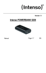
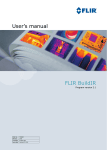
UNCOOLED FPA Infrared Thermal Imaging Camera TV304 Operator’s manual Testboy reserves all rights for amendment without prior notice TV304 User’s Manual Warnings & Cautions The infrared camera is a precision instrument and uses a very sensitive IR detector. Pointing the camera towards highly intensive energy sources-such as sun or devices emitting laser radiation or reflections from such devices-may affect the accuracy of the camera, or even harm-or irreparably damage-to the detector, whether the power supply of the camera is switch on or off. Avoid incorrect operation methods such as heavy pressing, shock or strong vibration during the course of transportation, store and installation, otherwise the product could be damaged. For protective reason please keep the product in the environment between -25°C and +60°C during the course of transportation and store. Original packaging box should be used during transportation. For protective reason the camera should be stored in shady, dry and draughty environment avoids electromagnetic interference. Avoid contaminating and damaging the lens surface by oil stain or chemicals. Cover the lens cap after use. Backup is recommended to avoid latent loss of data. Please copy (back up) the data regularly. Please take out the battery if the camera out of use for a long time, otherwise the product could be damaged. I TV304 User’s Manual Warranty All products manufactured by Testboy are warranted against defective materials and workmanship for a period of one year from the delivery date of the original purchase, provided such products have been under normal storage, use and service, and in accordance with TESTBOY’s instruction. The warranty extends only to the original purchaser and is not transferable. It is not applicable to any product which has been subjected to misuse, neglect, accident or abnormal conditions of operation. Expendable parts are excluded from the warranty. In the event of a defect in a product covered by this warranty the product shall not be further used in order to prevent additional damage. The purchaser shall promptly report any defect to TESTBOY or this warranty will apply. TESTBOY will, at its option, repair or replace any such defective product without charge if it, upon inspection, proves to be defective in material or workmanship and provided that it is returned to TESTBOY within the said one-year period. TESTBOY has no other obligation or liability for defects than above set forth. No other warranty is expressed or implied. TESTBOY specifically disclaims the implied warranties of merchantability and fitness for a particular purpose. TESTBOY shall not be liable for any direct, indirect, special, incidental or consequential loss or damage, whether based on contract, tort or any other legal theory. II TV304 User’s Manual Copyright © TESTBOY have all rights reserved worldwide. No parts of the software including source code may be reproduced, transmitted, transcribed or translated into any language or computer language in any form or by any means, electronic, magnetic, optional, manual or otherwise, without the prior written permission of TESTBOY. This manual must not, in whole or part, be copied, photocopied, reproduced, translated or transmitted to any electronic medium or machine readable form without prior consent, in writing, from TESTBOY. Trademarks ® TESTBOY is registered trademark. Quality Assurance The Quality Management System under which these products are developed and manufactured has been certified in accordance with the standard for ISO 9001. TESTBOY is committed to a policy of continuous development; therefore we reserve the right to make changes and improvements on any of the products described in this manual without prior notice. III TV304 User’s Manual Content 1 INTRODUCTION..................................................................................................................... 1 2 TECHNICAL SPECIFICATIONS............................................................................................. 2 3 PERIPHERALS....................................................................................................................... 4 3.1 STANDARD PERIPHERALS..................................................................................................................4 3.2 OPTIONAL ACCESSORIES...................................................................................................................4 4 APPEARANCE ....................................................................................................................... 5 5 INTERFACE............................................................................................................................ 7 6 KEYBOARD DESCRIPTION .................................................................................................. 8 7 TUTORIALS............................................................................................................................ 9 7.1 BATTERY OPERATION ........................................................................................................................9 7.1.1 Load the battery ........................................................................................................................9 7.1.2 Unload the battery...................................................................................................................10 7.2 QUICK OPERATION .......................................................................................................................... 11 7.2.1 Capture an image .................................................................................................................... 11 7.2.2 Color and scale ....................................................................................................................... 11 7.2.3 Saving an image ......................................................................................................................12 7.2.4 Opening an image ...................................................................................................................12 7.2.5 Transmit an image...................................................................................................................12 8 OPERATION GUIDE............................................................................................................. 13 8.1 SCREEN OBJECTS.............................................................................................................................13 8.1.1 Moving Temperature spot........................................................................................................14 8.1.2 Level and Span ........................................................................................................................14 8.2 MENU FUNCTIONS ...........................................................................................................................15 8.2.1 Measurement ...........................................................................................................................16 8.2.2 Level/Span...............................................................................................................................16 8.2.3 Setup menu ..............................................................................................................................16 8.2.4 File menu.................................................................................................................................22 9 TROUBLESHOOTING.......................................................................................................... 25 10 APPENDIX MATERIAL EMISSIVITY.................................................................................. 27 i TV304 User’s Manual 1 Introduction Thank you for choosing the TV304 infrared thermal imaging camera. The TV304 is a small and light handheld thermal imaging camera. It uses advanced uncooled microbolometer. The camera is designed for variety applications including electrical predictive maintenance, security, medical thermography, rescue and so on. The camera is very easy to use and is operated by using a few buttons which are conveniently placed on the camera. The compact design offers advanced features such as finger-tip controls, high quality thermal images, on-board image processing, large capacity memory and versatile USB connectivity. TV304 camera can be used as Power Supply: Thermal condition checking, fault & defect diagnosis on transmission lines and power equipment. Petrol-Chemical: Inspection of oil pipeline, detection of material surfaces, heat spilling, as well as on heat-preservation structure, power equipment, etc. Fire fighting: Forest-fire prevention, searching for latent source of ignition, preventive detection on specific material auto-ignition, and safety detection on electrical device for fire-prevention. Medical treatment: Body temperature measurement and analysis of temperature distribution. Others: Multiple-purpose for railway industry, construction industry, scientific research, etc. 1 TV304 User’s Manual 2 Technical Specifications Table 2.1 Technical Specifications Detector Type Focal Plane Array (FPA), uncooled microbolometer Resolution 384×288 Image Thermal Sensitivity Performance Field of View/ Min Focus Distance Image display Measurement Image storage 0.06℃ @30℃ 16°×12°/0.5m Focusing Method Manual Spatial Resolution 0.88 mrad LCD display Built-in High resolution color 2.8”LCD Temperature range ﹣20℃~500℃ Accuracy ±2℃ or ±2% of reading whichever is greater movable spot 4 Movable area 3 Line profile √ Max and Min temperature for areas √ Average temperature for areas √ Isotherms √ Temperature Difference √ Alarm(voice, color) √ Palette 11 palettes changeable Image storage 1000 images File format JPEG;14 bit thermal measurement data included Voice annotation 40 seconds voice record along with every image Laser Pointer Power Environmental characteristics Class 2, 1mW/635nm (red) Battery type Li-Ion, rechargeable Battery operating time 3 hours continues Power saving √ Operating temperature ﹣15℃~+50℃ Storage temperature ﹣25℃~+60℃ 2 TV304 User’s Manual humidity Operating and storage:≦90% non-condensing Physical characteristics Weight 0.91 kilogram Dimension 310×127×90mm Power Interface input √ Audio output √ Video output PAL/NTSC Output impedance 75ohm USB √ SD Card SD Card(1G) 3 TV304 User’s Manual 3 Peripherals 3.1 Standard Peripherals TV304 infrared camera and its accessories are delivered in a hard transport case. The system comprises:: TV304 infrared camera USB cable Transport case User’s manual Two SAMSUNG L160 Battery charger Lens cap Audio adaptor cable Video cable Browse software Earphone lithium batteries 3.2 Optional Accessories Optional accessories include: 75mmlens Analyzing software 4 TV304 User’s Manual 4 Appearance 1 2 3 4 5 5 TV304 User’s Manual 6 7 8 Figure 4.1 TV304 camera appearance Table 4.1 Appearance Description Number ① Lens, manually focusing ② Tripod fix point LCD display ③ Keyboard , it will be described in chapter 6 ④ Battery position ⑤ Output interface cover ⑥ Laser indicator ⑦ Tripod mounting point ⑧ Shortcut trigger User-defined function,default setting is laser indicator 6 TV304 User’s Manual 5 Interface 1 2 3 4 Figure 5.1 Interface Table 5.1 Interface Description Number ① ② ③ ④ Description S type connector. For connecting video cable and audio cable. External power connector USB interface For the thermal imager and computer data transmission. SD card slot Note: The USB connector will show the images in the internal FLASH by default, please use SD card reader to browse the saved images in SD card. 7 TV304 User’s Manual 6 keyboard description Figure 6.1 Keyboard Table 6.1 Keyboard Description Name Description Selections/ Auto Hold this for three seconds to get the best image automatically. Press this to set the emissivity, measurement method and palette alternately. Cancel Cancel the current operation. Exit a menu, dialog box, or a prompt window. Return to the real-time measurement mode. Press Confirm to show the pull up menu. Press Confirm to save the changes and exit. Press direction buttons to change the menu. Press direction buttons to move the spot position. If palette is chosen,press left/right button to change If the imager is in manual adjustment condition, press up/down button to change the temperature limit of the palette. Power Switch Hold this button for three seconds to switch on/off the power. Frozen/Save key Press the button to freeze the image. Press again to save the frozen image. Hold the button to save a live image. Power indicator Indicate the imager´s operating state Directions /Confirm 8 TV304 User’s Manual 7 Tutorials 7.1 Battery Operation 7.1.1 Load the battery The battery compartment is located in the handle of the unit. To open the battery compartment just simply hold the release trigger, and take it out. Release Trigger Figure 7.1.1.1 Position of Release Trigger Put the battery in the battery box with the connectors facing to each other. Then keep it steadily flat. The connectors are shown by the arrows below. Figure 7.1.1.2 Position of connectors Then put the battery in the compartment, hold and push it forward,until it is optically charged. 9 TV304 User’s Manual Figure 7.1.1.3 direction of charging the battery To replace the battery cover back just insert the forward part of cover to the notch,and press the backwards to lock the release trigger. Notch 7.1.2 Unload the battery To unload the battery, just take off the cover by pressing the release trigger. Release trigger Figure 7.1.2.1 Position of the release trigger Then hold the battery and pull it backward to take it out. Figure 7.1.2.2 Direction of unload the battery 10 TV304 User’s Manual Put the cover to the box and push down the cover buckle to finish the unloading operation. 7.2 Quick Operation 7.2.1 Capture an image Please follow the steps below to capture an infrared image: step Operation 1 Put the battery in the compartment. 2 Hold the ON/OFF power button to switch on the camera. Then wait for a few seconds to let the machine start up. 3 Point the camera to a warm object. You can press and hold the ‘F’ trigger to turn on the laser indicator to exactly locate the target. 4 Adjust the lens ring clockwise or anticlockwise to obtain the best display. 5 Move the target object to the center of the screen, if the target becomes unclear, adjust the lens ring again to get the best focus. 6 Press and hold down the ‘A’ button to calibrate the focus automatically. If different position is needed to measure, just press ‘S’ button to freeze the image, and press ‘A’ button to select the point, and then move the point to the position of the target. 7 8 If multiple points need to be measured, or even areas need to be measured, press to call the main menu function. Choose ‘Measurement’ to add points, profile and areas to the screen, but there are 4 points, 1 horizontal or vertical profile, and 3 areas can be added at most. Details can be consulted in chapter 8. Note: When the temperature of the target object is higher or lower than the value of corresponding camera temperature range, the temperature value shown on the screen will be in the form of <XXX°C or >XXX°C. 7.2.2 Color and scale In some occasions, you may find out that the images you have captured do not appear satisfying. You can change the color palette prior to saving the image and can change the palette of the image. There are eleven different Palette scales available. To switch between the palettes, you just need to press ‘A’ button continually to choose the scale until the scale is shown in yellow frame. Then press left, right button to switch between the palettes. Note: you need to press ‘A’ button several times to go to the palette change function. The scale will be framed in yellow, but not the temperature value, the temperature value framed in yellow is used for adjusting the level and span manually. 11 TV304 User’s Manual 7.2.3 Saving an image There are four ways to save the current thermal image: Methods 1 Operation If an image has been frozen, press ‘S’ button again to save the frozen image. 2 If an image has been frozen, press the Confirm button(the middle button of the joystick) to show the pull up menu, select “File”, and “Save” to save the image to the memory. 3 If the unit is in live mode, hold ‘S’ button for three seconds to save the current live image. 4 Set the shortcut trigger to “Save”, then press the shortcut trigger to save the image. 7.2.4 Opening an image Please follow the descriptions below to open an image Steps Operation Press Confirm button to activate the main menu,choose “File” and then “Open” to show the saved 1 images. The images’ name will be shown as IR_XX(position of the current image/total images) on the left top corner. Move the joystick left or right to change the current displaying image. 2 3 Press ○,Cbutton to exit the operation, and back to the measuring mode. 7.2.5 Transmit an image The imager can be connected to a computer by the attached USB cable. Use the given software to analysis or manage the images. Note: Please use the imager’s own function to format the FLASH memory. The format operation on the computer is not recommended. 12 TV304 User’s Manual 8 Operation guide 8.1 Screen objects 1 3 2 4 5 6 7 8 9 10 Figure 8.1 Screen Objects Table 8.1 Screen Objects Number Name Description 1 Pull up menu To display the system management menu 2 TESTBOY logo To display the logo of TESTBOY 3 Result table To show the value of spot measurement result 4 Status message To display the status of system, like ‘Frozen’ or ‘LS’ 5 Spot position Temperature measurement mode, which appears as a cross cursor. 6 Emissivity To indicate the current value of object emissivity 7 Lower temperature limit value To indicate the underflow temperature on the color scale 13 TV304 User’s Manual 8 Temperature scale To show the scale of the thermal image 9 Upper temperature limit value To indicate the upper flow temperature on the color scale 10 Battery level To indicate the battery status 8.1.1 Moving Temperature spot Live measuring mode Measuring point 1 Measuring point 2 Figure 8.1.2 Moving a spot 1 In the live measuring mode, press’A’ button to choose the measuring point, then the cross cursor and the measured temperature will be shown in yellow, at the same time, the suffix mark of the cross cursor “1” will be changed to “*”. 2 when the measuring spot has been chosen, use up, down, left, right button to move the spot, and the temperature of different position will be shown up on the right top corner at the same time. Note: press ‘A’ button to select the point measurement, palette, manual/auto, or emissivity alternately. 8.1.2 Level and Span (A)decrease the temperature span (B)increase the temperature span 14 TV304 User’s Manual (C)decrease the measuring level (D)increase the measuring level Figure 8.1.4 Level and Span 1. Press ‘A’ button to choose the scale and enter the manual adjustment. Then the limit temperature will be shown in yellow and the screen will display “LS” on the left top corner. 2. When the scale is under current operation, press left button to decrease the temperature span, shown as Figure 8.1.4(A). 3. When the scale is under current operation, press right button to increase the temperature span, shown as Figure 8.1.4(B). 4. When the scale is under current operation, press down button to decrease the temperature level, shown as Figure 8.1.4(C). 5. When the scale is under current operation, press up button to increase the temperature level, shown as Figure 8.1.4(D). 6. When the scale is under current operation, press ‘C’ button to exit the manual operation. 8.2 Menu functions The menu system is including four main groups Measurement, Level/Span, File and Setup. This section describes all menu functions in details. Figure 8.2.1 Main Menu 15 TV304 User’s Manual 8.2.1 Measurement This function is used to add or delete object measurement. Choose and confirm will show the following dialogue box. This function contains command of ‘Add Spot’, ‘Horizontal Line’, ‘Vertical Line’, ‘Add Area’, and ‘None’. There are at most four points, one profile, and three areas can be added at the same time. If choose ‘None’, then press confirm button, it will delete all the measurements. To delete a single object measurement, user can press “A” button to activate it, and then press C button to delete it. 8.2.2 Level/Span This function is used to activate the level and span function; It is the same function as which is mentioned before in chapter 8.1.3. Choose this function to go to the Level/Span function directly, instead of continually pressing Use direction keys to adjust the value. 8.2.3 Setup menu Figure 8.2.2 Submenu of Setup 16 ○,A button. TV304 User’s Manual 8.2.3.1 MeasureSet Figure 8.2.2.1 Measuring Setup Temperature range:Display temperature range of the camera. If the measured temperature exceeds the range, the accuracy of the measurement can’t be ensured. Temperature unit: there are three temperature units: °C, F, K to suit different situations. Ambient Temperature: when the system starts, it will check the environment temperature once. Also it can be adjusted manually. Reference temperature measurement: user can turn on, or turn off the reference temperature measurement. When it is on, the temperature results shown on the screen are all the differences between the object’s temperature and the reference temperature. Reference temperature: Effective only when reference temperature measurement is on. Can choose a constant temperature as the reference temperature, and also can choose an object’s temperature as reference temperature. 8.2.3.2 MeasureCorr Figure 8.2.3.2 Measuring Correct 17 TV304 User’s Manual Emissivity:To set the emissivity, press left or right key to adjust. TCorrect:To setup system’s temperature correction.(normally set by manufacturer) Distance: The distance between the machine and objects. Need to be set manually. (It is better to use the actual distance within 10 meters, and farther than 0.5 meter) Humidity: Current environment relative humidity. TReflect:To setup the system’s reflecting temperature.(normally set by manufacturer) 8.2.3.3 Analysis Figure 8.2.3.3 Analysis Setup Temp alarm: To turn on or off the temperature alarm. It is only efficient when doing area temperature measurement. When it is turned on, and if the temperature is in the alarming temperature area, the buzzer will automatically run and the region will be shown as the alarming color. The alarm color can be set at ‘alarming color’ column. Alarming Temp: set an alarm temperature. This function is only efficient when temperature alarm is on. Alarming Color: there are 9 colors to choose. When choose ‘auto’ it will not change the original color of the screen. Isothermal color: same as alarming color. Isothermal temperature: the temperature of the isothermal central point. Isothermal width: The value of a symmetry region around the central isothermal point. If the isothermal temperature is 50°C, isothermal width is 2°C, then the isothermal range will be 49°C ~ 51°C. 18 TV304 User’s Manual 8.2.3.4 Date & Time Figure 8.2.3.4 Date/Time dialog box Set date and time, via submenu, when the Date & Time dialog box is displayed on the screen. Use the up/down button to select an item. Use the left/right button to change an item value. The parameter item will be automatically saved by the system. Item selected will be highlighted in blue. Note: Need to reset the time and date when not in use for a long time, as internal battery’s power is limited. 8.2.3.5 Local Adapt Setup Figure 8.2.3.5 LocalAdapt Setup dialog box Point to the Local Adapt and press the confirm button to display the Local Adapt Setup dialog box. Language: There are two languages can be changed: English and Chinese. Auto Calib: Auto calibration time. Press left and right key to adjust. Short press will change the value by 1, and deep press will change the value by 10. 19 TV304 User’s Manual Video Mode: There are two video mode can be chosen, PAL or NTSC. Quick Access: Define the function of the shortcut key Set as ‘laser pointer’, press shortcut key to turn on or turn off the laser pointer. Set as ‘spot measurement’, press shortcut key to add or delete a spot. Set as ‘select color scale’, press shortcut key to a select color scale. Set as ‘save’, press shortcut key to save an image. Stand by Time: Navigate the integration button to specify the time after which the display will be switched off if it is not used. Choose ‘None’ to switch off this function. Auto Off Time: Navigate the integration button to specify the time after which the camera will be turn off if it is not used. Choose ‘None’ to switch off this function. Note: The camera program will be restarted when you change the language. This will take a few seconds. 8.2.3.6 System information Figure 8.2.3.6 System Information dialog box This is to display the device information: the device ID number; version of operation system and time of manufacture will be shown on the screen. 8.2.3.7 Factory Default Figure 8.2.3.7 Reset of Factory Default Restore the factory default setup. When the Restore default dialog box displayed on the screen, press the Central Confirm button to restore, and press C button to quit. Note: This function will remove all the settings made by user. The camera will be restarted when you restore factory settings. This will take a few seconds. 20 TV304 User’s Manual Factory setting parameter table Parameter Value Emissivity 0.96 Color scale On Data field On Language ENGLISH Temp Unit ℃ Shortcut key laser pointer Screen Turn off time None Battery turn off time None 21 TV304 User’s Manual 8.2.4 File menu The file menu contains all the functions dealing with the digital image, with four submenus of Open, Save, Delete and Format. Figure 8.2.2 Submenu of File 8.2.4.1 Open This function is used to open saved images form built-in flash. The function brings up the saved image on the screen directly. 1 2 Figure 8.2.1.1 information of saved image [1] File number: Display the opened image information (file number/total images been saved) [2]. Emissivity: Display emissivity of the opened image. Press the “C” button to go to live mode. 22 TV304 User’s Manual 8.2.4.2 Save Point to Save and press confirm button to save the displayed image to the internal flash memory or the compact Flash card. Figure 8.2.1.2 Saving an image 8.2.4.3 Delete Figure 8.2.1.3 Deleting an image Point to Delete and press the confirm button to display Del dialog box. Press confirm button to delete the opened image. Press the confirm button or C button to delete the image or not. 23 TV304 User’s Manual 8.2.4.4 Format Figure8.2.1.4 Format the Disk Point to Format and press the confirm button to display the Format dialog box. Press the confirm button or C button to format the Flash card or not. Note: This function will delete all data on the FLASH card and cannot be recovered. 24 TV304 User’s Manual 9 Troubleshooting In the case that infrared camera may experience problem, please carry through the following examine and repair. If the problem can’t be solved, please remove the power and contact our maintenance department. Symptom Reason and Resolve There is no battery in the battery compartment. →Insert a fully charged battery. Can’t start camera Battery is depleted →Change the battery. Auto turns off to protect camera. →Restart 5 seconds later. Battery is depleted →Change the battery. Camera auto turn off The camera may have been switched off automatically due to the settings in the Local Adapt Setup dialog box. →Press ON/OFF to switch on the camera. Environment temperature is too low Battery didn’t charge completely. Battery goes fast →Recharge the battery. Battery died, and is not rechargeable. →Use another battery. No thermal image Forgot to remove the lens cover. →Remove the lens cover. Under the image frozen state. →Press ‘C’ button to return to the real-time image. The thermal image turns to black and white →Restart the camera. Switch video output between NTSC and PAL. Whether or nor choose the black and white palette. The distance is not right. → the best distance to the object is 2 meters. The measured temperature is not correct → make sure the lens focus is suitable. Hold A button to adjust the lens The measuring method is not right. focus. → the environment may cause the problem, wait for a few minutes to let 25 TV304 User’s Manual the imager warming up. The target is too small. →get close enough to the target. Caused by the measuring environment →use scientific method to optimize the negative effects, the wind, dust and oxidation need to be concerned. The imager is too old to use. → please contact our company. 26 TV304 User’s Manual 10 Appendix Material Emissivity (Only for reference) Material Temperature(°C)Emissivity(ε) Exterior Status Non-oxidation 100 0.20 Oxygenated 100 0.55 Brown after grinding 20 0.40 Dull luster 38 0.22 Oxygenated 100 0.61 seriously oxygenated 20 0.78 Oxygenated 100 0.74 Rusty 25 0.65 Oxygenated 200 0.64 Non-oxygenated 100 0.21 Quarry-faced 25 0.94 Glazed 38 0.35 Polished 38 0.28 Nickel Non-oxygenated 200 0.37 Stainless steel Oxygenated 60 0.85 Steel Oxygenated in 200 0.79 Common brick Surface 20 0.93 Concrete Surface 20 0.92 Glass polished plate 20 0.94 White 100 0.92 Black 100 0.97 Smoke black 25 0.95 Candle soot 20 0.95 Rough lead surface 20 0.98 Oil Paint Mean value of 16 colors 100 0.94 Paper White 20 0.93 Aluminum Brass Copper Iron Cast iron Wrought iron Lacquer Carbon 27 TV304 User’s Manual Elektrotechnische Spezialfabrik Testboy GmbH, Beim Alten Flugplatz 3, 49377 Vechta, Germany Tel: +49(0)4441/89112-10 - Fax: +49(0)4441/84536 Internet: http://www.testboy.de – e-Mail: [email protected] 28