1
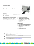
AXL AI 8 (-ME)
Axioline analog input module, 8 inputs,
2-wire connection method
AUTOMATION
Data sheet
7989_de_02c01
1
© PHOENIX CONTACT 2011-12-13
Description
The module is designed for use within an Axioline station.
It is used to acquire analog voltage and current signals.
Features
–
–
–
–
–
–
Eight analog, bipolar input channels to connect either voltage or current signals
Connection of sensors in 2-wire technology
Voltage ranges: 0V ... 10V, ±10V, 0V ... 5V, ±5V
Current ranges: 0mA ... 20mA, 4mA ... 20mA, ±20mA
Device type label stored
Status and diagnostic indicators
This data sheet is only valid in association with the UMENAXLSYSINST user manual.
Make sure you always use the latest documentation.
It can be downloaded from the product at www.phoenixcontact.net/catalog.
AXL AI 8 (-ME)
2
Table of contents
1
Description .............................................................................................................................. 1
2
Table of contents ..................................................................................................................... 2
3
Ordering data .......................................................................................................................... 3
4
Technical data ......................................................................................................................... 3
5
Tolerance data......................................................................................................................... 6
6
Internal circuit diagram ............................................................................................................ 7
7
Terminal point assignment....................................................................................................... 7
8
Connection examples .............................................................................................................. 8
9
Connection notes .................................................................................................................... 8
10
Local status and diagnostic indicators ..................................................................................... 9
11
Process data.......................................................................................................................... 10
12
Significant values in various formats...................................................................................... 11
12.1 Significant values in "IB IL" format .......................................................................................... 11
12.2 Significant values in S7-compatible format ............................................................................... 11
12.3 Calculation of the measured value from the process data input value .............................................. 12
13
Parameter, diagnostics and information (PDI) ....................................................................... 12
14
Standard objects ................................................................................................................... 13
14.1 Objects for identification (device rating plate) ............................................................................ 13
14.2 Object descriptions ............................................................................................................ 14
14.3 Diagnostics objects ............................................................................................................ 15
14.4 Objects for process data management .................................................................................... 16
15
Application objects ................................................................................................................ 17
15.1 Parameter table (0080hex: ParaTable) .................................................................................... 17
15.2 Measured value in extended float format (0082hex: Measured Value Float) ..................................... 18
16
Device descriptions ............................................................................................................... 18
7989_de_02c01
PHOENIX CONTACT
2
AXL AI 8 (-ME)
3
Ordering data
Description
Type
Order No.
Pcs./Pkt.
Axioline analog input module, 8 inputs: 0 - 10V, ±10V, 0 - 20mA,
4 - 20mA, ±20mA, 2-wire connection method (including bus base module
and connector)
AXL AI 8
2688064
1
Axioline analog output module, 8 inputs: 0 - 10V, ±10V, 0 - 20mA, 4 20mA, ±20mA, 2-wire connection method (electronic module as a replacement for item 2688064 AXLAI8)
AXL AI 8-ME
2688187
1
Accessories
Type
Order No.
Pcs./Pkt.
Axioline bus base module ( Replacement item )
AXL BS
2688129
5
Axioline shield connection set (contains 2 busbar holders and 2 SK 5 shield
connection clamps)
AXL SHIELD SET
2700518
1
Zack marker strip for Axioline (device labeling), in 2 x 20.3 mm pitch, unprinted, 25-section, for individual labeling with B-STIFT 0.8, X-PEN, or
CMS-P1-PLOTTER ( Marking )
ZB 20,3 AXL UNPRINTED
0829579
25
Zack marker strip flat for Axioline (connector/slot labeling), in 1 x 5.8 mm +
4 x 10.0 mm pitch, unprinted, 50-section, for individual labeling with BSTIFT 0.8, X-PEN, or CMS-P1-PLOTTER ( Marking )
ZBF 10/5,8 AXL UNPRINTED
0829580
50
Documentation
Type
Order No.
Pcs./Pkt.
User manual, English, Axioline: System and installation
UM EN AXL SYS INST
-
-
4
Technical data
Dimensions (nominal sizes in mm)
Width
126,1
51,6
122,4
53,6
53.6 mm
Height
126.1 mm
Depth
51.6 mm
Note on dimensions
The depth is valid when a TH35-7.5 DIN rail is used (according to EN60715).
General data
Color
Gray
Weight
204 g
Ambient temperature (operation)
-25 °C ... 60 °C
Ambient temperature (storage/transport)
-40 °C ... 70 °C
Permissible humidity (operation)
5 % ... 95 % (according to DIN EN 61131-2)
Permissible humidity (storage/transport)
5 % ... 95 % (according to DIN EN 61131-2)
7989_de_02c01
PHOENIX CONTACT
3
AXL AI 8 (-ME)
General data
Air pressure (operation)
70 kPa ... 106 kPa (up to 3000 m above sea level)
Air pressure (storage/transport)
70 kPa ... 106 kPa (up to 3000 m above sea level)
Degree of protection
IP20
Protection class
III, IEC 61140, EN 61140, VDE 0140-1
Connection data
Type of connection
Spring-cage connection with direct plug-in method
Conductor cross section, solid
0.2 mm² ... 1.5 mm²
Conductor cross section, stranded
0.2 mm² ... 1.5 mm²
Conductor cross section [AWG]
24 ... 16
Interface Axio bus
Type of connection
Bus base module
Transmission speed
100 Mbps
Communications power
Communications power Ubus
5 V DC (via bus base module)
Current consumption from Ubus
Typ. 105 mA , max. 130 mA
I/O supply
Supply of analog modules UA
24 V DC
Maximum permissible voltage range
19.2 V DC ... 30 V DC ( including all tolerances, including ripple )
Current consumption from UA
Typ. 35 mA , max. 45 mA
Surge protection
Electronic (35 V, 0.5 s)
Protection against polarity reversal
Polarity protection diode
Transient protection
Suppressor diode
Analog inputs
Number of inputs
max. 8 (differential inputs, voltage or current can be chosen separately)
Type of connection
Spring-cage connection with direct plug-in method
Connection method
2-wire (shielded, twisted pair)
Current input signal
0 mA ... 20 mA , 4 mA ... 20 mA , -20 mA ... 20 mA
Voltage input signal
0 V ... 5 V , -5 V ... 5 V , 0 V ... 10 V , -10 V ... 10 V
Resolution A/D
16 bits
A/D conversion time
2 μs
Limit frequency (3 dB)
30 Hz , 12 kHz (in fast mode)
Measured value representation
16 bits (15 bits + sign bit)
Data formats
IB IL, S7-compatible
Process data update
300 μs
Filtering
RFI filtering / passive TP 1st order
Input filter
30 Hz, 12 kHz and mean-value generation (can be parameterized)
Precision
0.1 % (of measuring range final value for active mean-value generation and 30 Hz
filter)
Transient protection of inputs
Suppressor diode
differential inputs, voltage
Number of inputs
8 (differential inputs, voltage)
Voltage input signal
0 V ... 5 V , -5 V ... 5 V , 0 V ... 10 V , -10 V ... 10 V
Input resistance of voltage input
268 kǥ (typical)
7989_de_02c01
PHOENIX CONTACT
4
AXL AI 8 (-ME)
differential inputs, voltage
Open circuit response
Goes to 0V
Common mode voltage range signal - ground
-50 V DC ... 50 V DC
Overload protection
±30 V DC, maximum
differential inputs, current
Number of inputs
8 (differential inputs, current)
Current input signal
0 mA ... 20 mA , 4 mA ... 20 mA , -20 mA ... 20 mA
Input resistance current input
104 ǥ (typical)
Open circuit response
Going to 0mA; open-circuit detection from 4 mA ... 20 mA
Overload protection
No; ±5.2VDC, maximum, Imax = 50mA
Electrical isolation/isolation of the voltage areas
5 V communications power (logic), 24 V supply (I/O)
500 V AC , 50 Hz , 1 min
5 V supply (logic)/functional earth ground
500 V AC , 50 Hz , 1 min
24 V supply (I/O) / functional earth ground
500 V AC , 50 Hz , 1 min
Mechanical tests
Vibration resistance in acc. with IEC 60068-2-6
5g
Shock test in acc. with IEC 60068-2-27
25 g, 11 ms period, half-sine shock pulse
Bump endurance test according to EN 60068-2-29
10 g
Conformance with EMC Directive 2004/108/EC
Noise immunity test in accordance with EN 61000-6-2
Electrostatic discharge (ESD) EN61000-4-2/IEC61000-4-2
Criterion B; 6 kV contact discharge, 8 kV air discharge
Electromagnetic fields EN61000-4-3/IEC61000-4-3
Criterion A; Field intensity: 10 V/m
Fast transients (burst) EN61000-4-4/IEC61000-4-4
Criterion B, 2kV
Transient surge voltage (surge) EN61000-4-5/IEC61000-4-5
Criterion B; supply lines DC: ±0.5 kV/±0.5 kV (symmetrical/asymmetrical); ±1 kV
to shielded I/O cables
Conducted interference EN61000-4-6/IEC61000-4-6
Criterion A; Test voltage 10 V
Noise emission test according to EN 61000-6-3
Radio interference properties EN 55022
Class B
Approvals
For the latest approvals, please visit www.phoenixcontact.net/catalog.
7989_de_02c01
PHOENIX CONTACT
5
AXL AI 8 (-ME)
5
Tolerance data
Tolerances influenced by electromagnetic interference
The following applies for tolerance values:
The data is valid for nominal operation (UA= 24V in the default configuration (unless documented otherwise).
Default configuration: Filter with 30 Hz, 16-sample mean-value, IBIL format.
300ǻs update time, fast mode (12 kHz filter, without meanvalue generation)
Tolerances at TA=25°C
Absolute
Relative
Typ.
Max.
Typ.
Max.
0V ... 5V, ±5V,
0V ...10V, ±10V
±50 mV
±80 mV
±0.5%
±0.8%
0mA ... 20mA,
4mA ... 20mA,
±20mA
±100 ǻA
±160 ǻA
±0.5%
±0.8%
Current
Voltage
Electromagnetic
fields
EN61000-4-3/
IEC61000-4-3
< ±1.0%
< ±2.0%
Fast transients
(burst)
EN61000-4-4/
IEC61000-4-4
< ±1.0%
< ±1.0%
Conducted interference
EN61000-4-6/
IEC61000-4-6
< ±0.5%
< ±0.5%
Additional tolerances may occur due to the influence of highfrequency electromagnetic interference caused by wireless
transmission systems in the near vicinity. The values specified refer to nominal operation in the event of direct interference to components without additional shielding such as a
steel cabinet, etc.
The above mentioned tolerances can be reduced by providing further shielding measures for the I/O module (e.g., use
of a shielded control box/control cabinet, etc.).
300ǻs update time, default (30 Hz filter, 16-sample average
value)
Tolerances at TA=25°C
Absolute
Relative
Typ.
Max.
Typ.
Max.
0V ... 5V, ±5V,
0V ...10V, ±10V
±10mV
±30mV
±0.10%
±0.30%
0mA ... 20mA,
4mA ... 20mA,
±20mA
±20ǻA
±60ǻA
±0.10%
±0.30%
Typical data contains offset error, gain error, and linearity
error in the respective default setting.
All tolerances indicated as a percentage are related to the positive measuring range final value.
Please also observe the values for temperature drift and the
tolerances under influences of electromagnetic interferences.
Tolerance and temperature response at TA = -25°C to
+60°C
Drift
Typical
Maximum
0V ... 5V, ±5V,
0V ...10V, ±10V
±40 ppm/K
±70 ppm/K
0mA ... 20mA,
4mA ... 20mA,
±20mA
±45 ppm/K
±85 ppm/K
The drift values refer to the relevant measuring range final value.
7989_de_02c01
PHOENIX CONTACT
6
AXL AI 8 (-ME)
6
Internal circuit diagram
7
Terminal point assignment
Supervisor
UBus
mC
Axio bus
8x
FE
#
U
D
UA
E1
E2
REF
M
U
X
8:1
U/I
X1
UANA
24 V
Bild 1
AI 1...8
Internal wiring of the terminal points
Key:
μC
00
10
20
30
01
11
21
31
02
12
22
32
03
13
23
33
04
14
24
34
05
15
25
35
06
16
26
36
07
17
27
37
D
UA
E1
E2
a1
00
01
02
03
04
05
06
07
a2
10
11
12
13
14
15
16
17
b1
20
21
22
23
24
25
26
27
b2
30
31
32
33
34
35
36
37
Microprocessor
Optocoupler
Power supply unit with electrical isolation
Bild 2
Terminal point assignment
Analog/digital converter
M
U
X
8:1
Multiplexer
Input amplifier for current (I) or voltage (U)
U/I
REF
Reference voltage source
Hardware monitoring
Supervisor
7989_de_02c01
TermiColor
Assignment
nal point
Supply voltage input
Supply of analog modua1, a2
Red
24 V DC
les (internally connected)
(UA)
b1, b2
Blue
GND
Reference potential of
the supply voltage (internally connected)
Analog inputs
00 ... 07 Orange U1+ ...
Positive voltage connecU8+
tion for channels 1 ... 8
10 ... 17 Orange U1- ... U8- Negative voltage connection for channels 1 ... 8
20 ... 27 Orange I1+ ... I8+ Positive current connection for channels 1 ... 8
30 ... 37 Orange I1- ... I8Negative current connection for channels 1 ... 8
PHOENIX CONTACT
7
AXL AI 8 (-ME)
8
Connection examples
The values of potentiometric position sensors can be acquired with voltage measurement. Supply the potentiometer via
an external power supply unit (Uext = 10V).
U1+ U2+
U1+ U2+
U
U
U1– U2–
U1– U2–
I1+
I1–
Bild 3
I2+
+24 V
I
I2–
I1+
I2+
I1–
I2–
I
Connection for voltage and current measurement
I
P
GND
Bild 5
Passive pressure sensor at a differential current
input
U1+ U2+
Uext
U1+ U2+
+
–
U1– U2–
I1+
I1–
Bild 4
+24 V
U1– U2–
I2+
I1+
I2+
I1–
I2–
U
P
GND
I2–
Connection of potentiometric position sensors
Bild 6
9
Differential voltage input with active 3-wire transmitter
Connection notes
Always connect the analog sensors using shielded, twisted
pair cables.
Unshielded cables may be out of the specified tolerances in
environments with heavy noise.
Connect the cable shield to functional earth ground, immediately when the cables enter the control cabinet.
If there is no closed control cabinet, connect the shield to a
shield bus.
For further information on shielding, please refer to the UMENAXLSYSINST user manual.
7989_de_02c01
PHOENIX CONTACT
8
AXL AI 8 (-ME)
10
Local status and diagnostic indicators
00
10
20
30
D
UA
E1
E2
Bild 7
Designation
D
04
14
24
34
05
15
25
35
06
16
26
36
07
17
27
37
Meaning
Red/
yellow/
green
Diagnostics of local bus communication
Power down
OFF
Device in (power) reset
Not connected
Red flas- Device operating, but there is no connection to previous device.
hing
Reset
Red ON
Application reset
Device operating, but there is still a connection to the previous device, the application is reset.
Ready
Yellow ON Device operating, there is still a connection to the previous device,
but the device has not yet detected a valid cycle after power on.
Valid data cycles have been detected, but the device is (not) yet
Connected
Yellow
flashing
part of the current configuration.
Device applica- Green/yel- Valid data cycles are being detected.
tion not ready
low alter- The master application set the output data to valid, however, the
nating
slave application has not set the input data to valid as yet.
Active
Green
Device operating, communications within the Axioline station is
flashing
OK.
The master application does not read the input data.
(The connection to the controller has not yet been established, for
example)
Run
Green ON Valid data cycles are being detected. All data is valid
ON
Supply of analog modules present
UAnalog
OFF
Supply of analog modules not present
Peripheral fault ON
I/O error present
OFF
No I/O error
Channel error
ON
Channel error present
OFF
Channel error not present
UA
E1
E2
03
13
23
33
Color
02
12
22
32
Local status and diagnostic indicators
01
11
21
31
Green
Red
Red
State
Description
Channel errors are errors that can be associated with a channel.
Periphery errors are errors that affect the entire
module.
For more information on the meaning of local
diagnostic and status indicators, please refer to
the UMENAXLSYSINST user manual.
7989_de_02c01
PHOENIX CONTACT
9
AXL AI 8 (-ME)
11
Error code and status of the E1 and E2 LEDs
Error
No error
Underrange
Overrange
Open circuit
Faulty supply voltage
Parameter table invalid
Device error
Flash format error
E1 LED
OFF
OFF
OFF
OFF
ON
OFF
OFF
OFF
E2 LED
OFF
ON
ON
ON
ON
ON
ON
ON
The error that can actually be reported depends on the measuring range. For additional
information please refer to the tables with significant measured values in various formats.
Process data
The module uses eight input process data words.
Each channel is mapped to a word.
Input words IN1 to IN8
The measured values are transmitted to the controller board
or the computer by means of the IN process data words IN1
to IN8.
The measured values are depicted in IBIL or S7-compatible
format. In both cases, the measured value is displayed in
16bit format. The data type is Integer16 from a technical programming point of view.
15 14 13 12
Analog value
11
10
9
8
7 6 5 4 3 2 1 0
In the IBIL format a diagnostic code is mapped to the input
data in the event of an error.
Code
(hex)
8001
8002
8004
8020
8040
8080
7989_de_02c01
Cause
Measuring range exceeded (overrange)
Open circuit
Measured value invalid/no valid measured
value available
Faulty supply voltage
Device faulty
Below measuring range (underrange)
PHOENIX CONTACT
10
AXL AI 8 (-ME)
12
Significant values in various formats
12.1
Significant values in "IB IL" format
Input data
hex dec
8001 Overrange
7F00 32512
7530 30000
0001 1
0000 0
FFFF -1
8AD0 -30000
8100 -32512
8080 Underrange
8002 Open circuit
0 V ... 10 V
SB
> +10.837
+10.837
+10.0
+333.33 ǻV
̣0
± 10 V
SB
> +10.837
+10.837
+10.0
+333.33 ǻV
0
-333.33 ǻV
-10.0
-10.837
< -10.837
0 V ... 5 V
SB
> +5.419
+5.419
+5.0
+166.67 ǻV
̣0
±5V
SB
> +5.419
+5.419
+5.0
+166.67 ǻV
0
-166.67 ǻV
-5.0
-5.419
< -5.419
0 mA ... 20 mA
mA
> +21.6747
+21.6747
+20.0
+0.6667 ǻA
̣0
± 20 mA
mA
> +21.6747
+21.6747
+20.0
+0.6667 ǻA
0
-0.6667 ǻA
-20.0
-21.6747
< -21.6747
4 mA ... 20 mA
mA
> +21.3397
+21.3397
+20.0
+4.0005333
+4.0 ... +3.2
< +3.2
±5V
SB
> +5.879
+5.879
+5.0
+180.85 ǻV
0
-180.85 ǻV
-0.3125
-5.0
-5.879
< -5.879
0 mA ... 20 mA
mA
> +23.5157
+23.5157
+20.0
+0.7234 ǻA
̣0
± 20 mA
mA
> +23.5157
+23.5157
+20.0
+0.7234 ǻA
0
-0.7234 ǻA
-1.25
-20.0
-23.5157
< -23.5157
4 mA ... 20 mA
mA
> +22.8142
+22.8142
+20.0
+4.0005787
+4.0
+3.9994
+3.0
< +1.1852
The maximum measured value is 7F00hex.
Depending on the format, the minimum measured value is either 0000hex or 8100hex.
12.2
Significant values in S7-compatible format
Input data
hex dec
7FFF Overrange
7EFF 32511
6C00 27648
0001 1
0000 0
FFFF -1
F940 -1728
9400 -27648
8100 -32512
8000 Underrange/open
circuit
0 V ... 10 V
SB
> +11.759
+11.759
+10.0
+361.69 ǻV
̣0
± 10 V
SB
> +11.759
+11.759
+10.0
+361.69 ǻV
0
-361.69 ǻV
-0.625
-10.0
-11.759
< -11.759
0 V ... 5 V
SB
> +5.879
+5.879
+5.0
+180.85 ǻV
̣0
The maximum measured value is 7EFFhex.
Depending on the format, the minimum measured value is either 0000hex or 8100hex.
7989_de_02c01
PHOENIX CONTACT
11
AXL AI 8 (-ME)
12.3
Calculation of the measured value from the process data input value
13
Parameter, diagnostics and information (PDI)
The following examples explain the calculation of the measured value from the process data input value for the measuring Parameter and diagnostic data as well as other information is
transmitted via the PDI channel.
range 4mA to 20mA.
PD IW = Process data input word = input data
For information on PDI, please refer to the
UMENAXLSYSPRO user manual.
IBIL format
Resolution = (20 mA - 4 mA) / 30000 = 0.0005333
Measured value = PD-EW x 0.0005333 mA +4 mA
Example 1
PD IW
Value x resolution
+ 4 mA
Measured value
493Fhex = 18751dec
18751 x 0.000533 mA = 10 mA
10 mA + 4 mA = 14 mA
14 mA
S7-compatible format
Resolution = (20 mA - 4 mA) / 27648 = 0.0005787
Measured value = PD IW x 0.0005787 mA + 4 mA
Example 1
PD IW
Value x resolution
+ 4 mA
Measured value
Example 2
PD IW
Value x resolution
+ 4 mA
Measured value
7989_de_02c01
The standard and application objects stored in the module are
described in the following section.
The following applies to all tables below:
Please refer to the UMDEAXLSYSPRO User Manual or the
basic profile for an explanation of the object codes and data
types.
Abbreviation
A
L
R
C
Meaning
Number of elements
Length of the elements
Read
Write
6C00hex = 27648dec
27648 x 0.0005787 mA = 16 mA
16 mA + 4 mA = 20 mA
20 mA
F940hex -> FFFFhex - F940hex + 1 =
-1728dec
-1728 x 0.0005787 mA = -1 mA
-1 mA + 4 mA = 3 mA
3 mA
PHOENIX CONTACT
12
AXL AI 8 (-ME)
14
Standard objects
Please refer to the basic profile for comprehensive information.
14.1
Objects for identification (device rating plate)
Index Object name
[hex]
Manufacturer
0001
VendorName
Object
code
Data type
A
L
Rights
Meaning
Contents
Var
Visible String
1
16
R
Phoenix Contact
0002
VendorID
Var
Visible String
1
7
R
0003
VendorText
Var
Visible String
1
49
R
Manufacturer
name
Manufacturer
identification
Comment on the
manufacturer
0012
VendorURL
Var
Visible String
1
30
R
Module - special
0007
ProductName
Var
Visible String
1
12
R
AXL AI 8-ME
0008
SerialNo
Var
Visible String
1
11
R
Product designation
Serial number
0009
ProductText
Var
Visible String
1
24
R
000A
0037
OrderNumber
DeviceType
Var
Var
Visible String
Octet string
1
1
8
8
R
R
000B
HardwareVersion
Record
Visible String
2
14
R
000C
FirmwareVersion
Record
Visible String
2
16
R
000D
PCH version
Record
Visible String
2
24
R
0006
ProductFamily
Var
Visible String
1
3
R
7989_de_02c01
00A045
Components and
systems for industrial automation
URL of the manu- http://
facturer
www.phoenixcontact.com
xxxxxxxxxx (e.g.,
12345123456)
Product text
8 analog input
channels
2688187
Order No.
Module identifica- 00 20 00 10 00 00
tion
00 A0hex
Hardware version e.g., 2010-06-21;
01
Firmware version e.g., 2010-06-21;
V1.10
Parameter chan- e.g., 2010-01-08;
nel version
V1.00
Product family
Axioline - High
speed I/O system
PHOENIX CONTACT
13
AXL AI 8 (-ME)
Index Object name
[hex]
Module - general
0004
DeviceFamily
000E CommProfile
Object
code
Data type
A
L
Rights
Meaning
Contents
Var
Var
Visible String
Visible String
1
1
14
4
R
R
I/O analog IN
633
000F
0011
DeviceProfile
ProfileVersion
Var
Record
Visible String
Visible String
1
2
5
33
R
R
Device family
Communication
profile
Device profile
Device profile version
0013
DeviceDescFile
Var
Visible String
1
28
R
003A
VersionCount
Array
Unsigned 16
4
2
R
File name of the
FDCML device
description file
Version counter
0017
Language
Use of the device
0014
Location
Record
Visible String
2
14
R
Language
Var
Visible String
1
59
R/W
0015
EquipmentIdent
Var
Visible String
1
59
R/W
0016
ApplDeviceAddr
Var
Unsigned 16
1
2
R/W
Installation location
Equipment identifier
User-defined device number
Data type
A
L
Rights
2
3
14.2
0010
2009-10-22;
Basic - Profile
V1.12
AXL_AI_8ME_dtmv00_1.00
.xml
e. g., 0005 0000
0000 0000
en-us; English
Please fill in ...
Please fill in ...
xx xxhex (e.g.,
0001)
Object descriptions
Index
[hex]
0038
Object name
ObjDescrReq
Object
code
Record
0039
ObjDescr
Record
16
003B
003C
PDIN_Descr
PDOUT_Descr
Record
Record
3
3
Read,
write
See su- Read
bindices
12
R
12
R
Meaning
Object whose description is requested
Description of the object whose index
was requested
Description of the IN process data
Description of the output process data
These objects are only important for tools and
are therefore not described in more detail here.
Please refer to the basic profile for comprehensive information.
7989_de_02c01
PHOENIX CONTACT
14
AXL AI 8 (-ME)
14.3
Index
[hex]
0018
0019
Diagnostics objects
Object name
DiagState
ResetDiag
Object
code
Record
Var
Data type
A
L
Rights
Assignment
Unsigned 8
6
1
21
1
R
C
Diagnostic state
Reset diagnostics
Diagnostics state (0018hex: DiagState)
This object is used for a structured message of an error.
0018hex: DiagState (Read)
Subindex
Data type
0
1
2
3
4
5
6
Record
Unsigned 16
Unsigned 8
Unsigned 8
Unsigned 16
Unsigned 8
Visible String
Length in
bytes
21
2
1
1
2
1
14
Meaning
Contents
Diagnostic state
Error number
Priority
Channel
Error code
More follows
Text (14 characters)
Complete diagnostics information
0 ... 65535dec
00hex
No error
Error
01hex
Warning
02hex
81hex
Error removed
Warning eliminated
82hex
No error
00hex
Channel 1
01hex
:
:
Channel 8
08hex
FFhex
Entire device
See table below
00hex (not supported)
See table below
The message with the priority 81hex or 82hex is
a one-time internal message to the bus coupler
that is implemented onto the error mechanisms
of the higher-level system by the bus coupler.
Error code and associated text
Error
No error
Underrange
Overrange
Open circuit
Faulty supply voltage
Parameter table invalid
Device error
Flash format error
7989_de_02c01
Error code
0000hex
8920hex
8910hex
7710hex
5160hex
6320hex
6301hex
6302hex
Text
Status OK
Underrange
Overrange
Open circuit
Supply fail
Invalid para
CS FLASH
FO FLASH
Priority
00hex
02hex
02hex
01hex
01hex
01hex
01hex
01hex
Channel
00hex
01hex ... 08hex
01hex ... 08hex
01hex ... 08hex
FFhex
FFhex
FFhex
FFhex
PHOENIX CONTACT
15
AXL AI 8 (-ME)
Reset diagnostics (0019hex: ResetDiag)
You can delete the diagnostics memory and acknowledge the
diagnostic messages with this object.
0019hex: ResetDiag (Write)
Subindex
Data type
0
Unsigned 8
Length in
bytes
1
06hex
Other
14.4
Index
[hex]
0025
0026
Meaning
Contents
Reset diagnostics
00hex
02hex
No action
Deletes and acknowledges all pending malfunctions that not been
read out
Deletes and acknowledges the entire diagnostics and allows no
further diagnostic messages
Reserved
Objects for process data management
Object name
PDIN
PDOUT
Object
code
Var
Var
Data type
A
L
Rights
Assignment
Octet string
Octet string
1
1
16
16
R
R
IN Process Data
OUT process data; not applicable
IN process data (0025hex: PDIN)
You can read the IN process data of the module with this object.
0025hex: PDIN (Read)
Subindex
Data type
0
Octet string
7989_de_02c01
Length in
bytes
16
Meaning
Contents
IN Process Data
The structure corresponds to the representation
in the "Process data" section.
PHOENIX CONTACT
16
AXL AI 8 (-ME)
15
Index
[hex]
0080
0082
15.1
Application objects
Object name
ParaTable
Measured Value
Float
Object
code
Array
Array
Data type
A
L
Rights
Assignment
Unsigned 16
Octet string
10
8
10 * 2
8*6
R/W
R
Parameter table
Measured values in the extended float
format
Parameter table (0080hex: ParaTable)
Parameterize the module using this object.
The parameterization is permanently stored on the module.
After resetting, the module works with the last permanently
stored data. If no permanent data was stored, the module
works with the default data.
0080hex: ParaTable (read, write)
Subindex
Data type
Meaning
Default value
0
1
:
8
9
10
Read/write all elements
Parameterization of channel 1
:
Parameterization of channel 8
Data format
Reserved
See subindices
0000hex
0000hex
0000hex
0000hex
0000hex
Length in
bytes
Array of Unsigned 16 10 * 2
Unsigned 16
2
Unsigned 16
2
Unsigned 16
2
Unsigned 16
2
Unsigned 16
2
Parameterization of channel 1 ... channel 8
Parameterization word:
15 14 13 12
0 0 0 Filter
11 10 9
8
0 0 Meanvalue
7 6 5 4 3 2 1 0
0 0 0 0 Measuring range
Filter
30 Hz (default)
12 kHz
Code (bin)
0
1
Measuring range
0V ... 10V (default)
±10V
0V ... 5V
±5V
0mA ... 20mA
±20mA
4mA ... 20mA
Reserved
Channel inactive
Code (bin)
0000
0001
0010
0011
0100
0101
0110
0111 ... 1110
1111
7989_de_02c01
Mean-value
16-sample (default)
No mean-value
4-sample
32-sample
Code (bin)
00
01
10
11
Data format:
15 14 13 12 11 10 9
8
7 6 5 4 3 2 1 0
0 0 0 0 0 0 Data for- 0 0 0 0 0 0 0 0
mat
Data format
IB IL (default setting)
Reserved
S7-compatible
Reserved
Code (bin)
00
01
10
11
PHOENIX CONTACT
17
AXL AI 8 (-ME)
15.2
Measured value in extended float format
(0082hex: Measured Value Float)
You can read the IN process data in Inline or S7-compatible
format with the 0025hex object.
Extended Float Format
The Extended Float Format is a specially defined format. It
consists of the measured value in the float format, a status
and a unit code.
The 0082hex object is also available.
Status is necessary because the float format defines no patThis object provides the measured value in the highest inter- terns providing information on the status of the numerical value.
nal accuracy of the terminal in the float format.
0082hex: Measured Value Float (Read)
Subindex Data type
Length in
bytes
0
Array of Octet 8 * 6
Strings
1
Octet string
6
:
8
:
Octet string
:
6
Meaning
Read all elements
Measured value
for channel 1
:
Measured value
for channel 8
Status corresponds to the LSB of the Inline diagnostic codes
(e.g. overrange: Status = 01, Inline diagnostic code =
8001hex). If Status = 0, the measured value is valid.
Unit code
Volt (V)
Milliampere (mA)
Code
58 (3Ahex)
39 (27hex)
Status
Measured value is valid
Measured value is invalid
Code
00hex
Other
channel 1 ... channel 8 measured value
16
Element
Data type
1
Float 32
Length in
bytes
4
2
3
Unsigned 8
Unsigned 8
1
1
Meaning
Value in the float
format acc. to
IEEE 754
Status
Unit code
Device descriptions
The device is described in the FDCML files (PCWORX) or
GSDML files (S7 Hardware configurator). The files can be
found at the bus coupler and can be downloaded at
www.phoenixcontact.net/download.
Structure of the float format according to IEEE 754 in the bit
representation:
VEEE EEEE
EMMM MMMM
MMMM MMMM
MMMM MMMM
SB
E
M
1 sign bit, 0: positive, 1: negative
8 bits exponent with offset 7Fhex
23 bits mantissa
Some example values for conversion from floating point to hexadecimal representation:
Floating point
1.0
10.0
1.03965528
- 1.0
7989_de_02c01
Hexadecimal representation
3F 80 00 00
41 20 00 0
3F 85 13 6
BF 80 00 00
PHOENIX CONTACT GmbH & Co. KG • 32823 Blomberg • Germany • Phone: +49-(0) 5235-3-00
PHOENIX CONTACT • P.O.Box 4100 • Harrisburg • PA 17111-0100 • USA • Phone: +717-944-1300
www.phoenixcontact.com
18