1
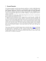
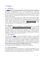
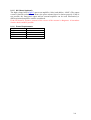
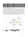
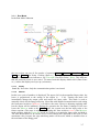
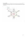
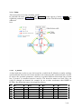
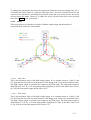
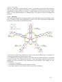
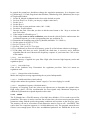
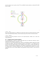
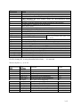
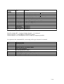
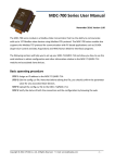
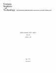
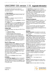
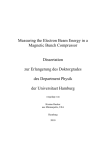
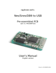
D-MOSTAB Vers. 6 KHM-FEB DESY 3055 Dr. Karl Hubert Meß 1-1 1 General Remarks The D_Mostab (digitally controlled monochromator stabiliser) is a double width NIM module to stabilise the intensity or spectral purity of a monchromatic X-ray beam at DORIS (or any other synchrotron light source). However, as the functionality of the unit is mainly determined by its firmware (software), the unit can be used in many regulation or filtering applications. The unit has two analogue inputs and one analogue output (0-10V, 16bit, sampling rate up to 100 ks/s). On demand two outputs can be provided. In addition a serial port can be used for a computer connection. The unit consists of a motherboard, a DSP (Digital Signal Processor) board, a communication processor board and an optional HV board. The operation mode and parameters can be changed either via the front panel, a fieldbus link or a RS232 connection such that it fits the condition at a particular beam line optimally. For up to 26 beam lines the optimal regulation parameters can be stored and retrieved locally and remotely as well. At boot loading time (after a reset) the last stored beam line number along with the last stored preferred operating mode are retrieved and the D_Mostab starts operating as before the last STORE action. This insures that local, temporal changes of the operating mode or the regulation parameters are reset to the default by pushing the reset button. This is true even for the beam line number. At the same time the user may choose and adjust the default values. This manual concentrates on technical aspects how to operate the unit. A Report (in German) on the performance of a prototype is available. Likewise technical details on the main-board, the DSP-board, the ADC/DAC-board, the communication-board, and the HV-board are available. Sample software for a PC-connection and the actual software version, ready to load into the DSP, are available for download. 1-2 2 Hardware 2.1.1 NIM-Cassette The figure 1 shows the front panel of the double width NIM unit. The RESET button reboots the DSP, starts the parameter update feature and starts the program with the preferred parameters in the preferred operation mode as saved in the flash memory. Normally the MANUAL/AUTO switch should be on AUTO (the red LED is not lit). Under special circumstances it may be preferred to switch to MANUAL. The two-row display, the knob and the ENTER button are used to manually change operation conditions and to set or adjust settings or parameters. Alternatively the Serial I/O interface can be used for this purpose. Details are explained below. Three Lemo connectors are used for the two analogue inputs IN0 and IN1 and the output. The user can choose whether the DSP should use input 0 or the ratio IN0/IN1. The output depends of course on the operation mode. The fourth connector provides a TTL-high signal whenever the input signal or input ratio is locked by the feedback. The green LED indicates the same optically. The High voltage switch enables the HV- Board (optional). The SHV output connector is situated on the back of the cassette. The HV output consists of the frontpanel output, shifted by –10V and amplified by a factor of hundred. 2.1.2 DSP Board The commercial DSP Board miniKit320C32 was selected because of its reasonable price/performance (http://www.dsignt.de/products/minikit/m32.htm). It consists of a 5o MFLOP floating point DSP with a synchronous serial port interface, 128 kB SRAM, 128kB flash memory, UART, 16 bit bi-directional host interface and an external bus interface. Normally the DSP boots off the flash memory. The memory can be written to either by conventional PROM burning or, in place, from the DSP. The DSP has a JTAG interface for debugging or loading. In order to use the JTAG interface a development board is needed. In addition the front panel serial I/O connection can be used. 2.1.3 Analogue Board The analogue board (figure2) sits on top of the DSP board. The inputs (0...10V) are shifted and attenuated by a differential amplifier. Two analogue to digital converters digitise the signals to one serial 32 bit word, however with a precision of 18 bit. The sampling rate is set to 32 ks/s. This is more than adequate to keep the phase-shift due to deadtime small and gives sufficient time to perform the regulation algorithm. A different algorithm may require a different sampling rate. The start of the digitisation is issued by a quartz timer. At the same time a 32-bit word is written to 2 digital to analogue converters. In the present application one of the two outputs is used as a window of 2V shifted by the other output by 0...8V. In this way the internal 18-bit resolution of the digital to analogue can be utilised. For other applications an analogue board exist with two full-scale outputs. The analogue board is under redesign because of shortage of a particular chip. 2.1.4 Communication Board The communication board fits into the miniKit320C32 footprint. It is implemented to free the DSP from the burden to operate the front-panel or the external fieldbus (CAN). Jumpers on the motherboard allow to route the fieldbus interface or the RS232 interface (part of the DSP board) to front panel connector. Note that the pinout is different in both cases. 2-3 2.1.5 HV- Board (optional) The high voltage board (figure3) acts as an amplifier (100 x) and shifter (-1000V). The output current is limited to about 2 mA. Hence, the piezo actuator has to be chosen properly. If this is not possible, the front-panel output and an external amplifier can be used. Alternatively a different internal amplifier could be considered. If the HV board is in place, removal of the covers of the cassette is dangerous. A hazardous electric shock could be possible. 2.1.6 +24 V +12V +6 V -6 V -12 V Power Requirements 6 mA 60 mA 510 mA 80 mA 2 mA 2-4 3 Software The software is mainly written in C. The code can be provided on request ([email protected]) or downloaded. It consists of • a service part that expects a RS232 connection to a PC at boot time, • a part that retrieves or saves information in the flash memory, • a part that does the communication with the user, • a part that locates the Bragg peak automatically • and the various algorithms to stabilise the x-ray beam intensity. Of special interest for the user are the communication package (MENU) and some aspects of the algorithm. There are four methods to operate and interact with the D-MOSTAB. A purely manual mode and three other methods that run concurrently, in principle. For the occasional user the front panel provides the easiest access. In the switch position AUTO (red LED off) a turning knob (fig(1)) and a push button, together with a 2x8 character display, let the user issue most commands and change most parameters in the local mode. (Note that the turning knob is speed sensitive; fast turning increases the step size exponentially.) In this mode the front panel display is updated regularly. The content is described below. The mode can also be emulated on the serial interface (second method). In this case the front panel actions are emulated by keystrokes and the 16-character output is routed to the terminal screen. Again it is updated regularly. The third method, called computer-based mode, has a different software protocol, more compact and better suited for a computer link. The 16-character output string is not updated. Both, the second and third method rely on a serial connection. If no communication board is installed and if the jumpers J25 and J26 connect the DSP board with the Sub D 9 connector (lower positions), the DSP can directly communicate over the RS232 connection with a computer, a terminal or a PC terminal program. If the communication board is installed and the jumpers are set in the upper position, the protocol depends on the settings of the communication board. In general it will be set to RS232 or CAN. However the same ASCII character based communication is used in both cases. Occasionally it may be preferred to avoid all unnecessary complication and to operate the unit solely to adjust the monochromator. In this case the upper left switch should be set to MANUAL. The red LED will be lit. Turning the knob will change the output steering the monochromator. The setting is displayed in the lower row on the screen. The upper row indicates the rescaled INPUT0 (or the ratio IN0/ IN1, depending on the setting of parameter TWOINPUT). Note that the computer link is still able to read, writing is however inhibited. The methods 1 and 2 are described under the topic MENU; the method 3 is explained under the topic Computer based communication. 3.1 Menu The front panel has two elements to enter commands and two lines of display, disregarding the MANUAL/AUTO switch that should normally be set to "AUTO" (red LED off). The turning knob can be turned stepwise either to the left (keyboard emulation: < ( x3C ) ) or to the right (keyboard emulation: > ( x3E)). The ENTER push button can be pushed once (keyboard emulation: ! ( x21 ) ) or, as a sort of DOUBLE CLICK, twice (keyboard emulation: | ( x7C)). 3-5 Front panel Turn knob left Turn knob right Push button once Push button twice Keyboard emulation < > ! | Keyboard emulation (in hex) 3C 3E 21 7C The somewhat odd emulation was forced because the CR and LF characters are used in the computer oriented communication method. The menu consists of three layers of command. Within one layer new topics are selected by the turning knob (or < > respectively). The choice is activated (i.e. the command layer below is entered) by pushing the ENTER knob once ( or ! ). The DOUBLE CLICK (or |) brings up one layer again. The name or meaning of the actual layer is displayed in the upper (left) 8 characters. The lower (right) 8 characters display the current choice for the lower layer, to which the turning knob is pointing. At the lowest layer it is possible to change values in prefixed steps or current measurement values are displayed. As a rule values have to be activated (entered) with two important exceptions. For obvious reasons it is convenient to change the setpoint or the output life, without the need to push the E NTER button (see below). The logical entry in the menu is of course the top entry, displaying MENU MENU. Here you get the choice to set the SET POINT, change the RUN MODE, select a new value to be displayed (VIEW) or use more implied operations (OTHER). 3-6 3.1.1 Run Mode In the Run Mode Submenu the user selects one out of five modes of operation:STD BY, MANUAL, SRCH PEAK, HOLD PEAK, and TRACK (Set Point). Clicking (Enter or ! ) on a particular mode will change the display as the blue arrows indicate to, say, TRACKSP (Track Set Point) DONE. This indicates that the particular mode is now active. To return from this display double-click (Enter Enter or | ) returns the display one layer up (red arrows). 3.1.1.1 Std by Stand By. No action. Only the communication packet is activated. 3.1.1.2 Manual In this case a pair of numbers is displayed. The upper (left) is the normalised input value, the lower is proportional to the setting of the output (0 ... 2^16). Turning the knob will immediately change the output value and maybe the input value. This mode is used to manually search for the Bragg reflection. (Note that with installed communication card setting the front-panel switch to "MANUAL" will achieve the same. However adjusting anything other but the output will be inhibited.) During the operation the Set Point is changed. If the user leaves the MANUAL mode to the TRACK mode, the system uses the last input value as the future setpoint. (The same is achieved by flipping the front switch to AUTO.) The MANUAL mode together with the TRACK S P mode are used to set a particular input value and hold it. The user should however be careful, not to exceed about 80% (depends on the noise) of the maximum value, because the edge stabilising mode will be used, which is unstable close to the maximum of the Bragg peak. 3-7 3.1.1.3 Srch Peak This mode searches for a peak. After completion it automatically approaches the selected SET POINT and switches to the TRACK mode. Be aware that the SET POINT should be set to below ca. 80% (i.e. |SetPoint|<0.8) in order to stabilise successfully on the edge. SRCH PEAK is the automatic start mode after a reboot unless the MANUAL mode was selected at the time of the last SAVE operation. The user is well advised to use the SRCH PEAK mode in case he/she does not understand the unit’s behaviour. 3.1.1.4 Hold Peak In this mode a different algorithm is used in trying to stay on top of the Bragg peak. Note that the mode produces the highest beam intensity, however there are two drawbacks unavoidably connected with it. Firstly the high frequency noise is enhanced and, secondly, the upper bandwidth for regulation is reduced considerably. The mode is useful for an almost stable, slowly varying beam (less than 1Hz), even when the beam is absent for some time. If the beam is very stable over very long periods of time the MANUAL mode will produce less high frequency fluctuations. 3.1.1.5 Track S P Track Set Point. This mode can be entered by hand or as part of the automatic sequence to stabilise on the edge. In the first case the Set Point is intrinsically changed to the actual input value prior to entering the Track mode. In the automatic sequence the value in the set-up values or a value recently changed by the user (SET POINT) will be utilised. 3.1.2 Set Point This menu is located at a relatively high level, because it is likely the only menu a casual user will need. By entering this menu point the knob (the > or < respectively) is switched on for immediate action. This menu point is entered on default after reboot. To leave use the Enter Enter (or | ). 3.1.3 View This menu point is used to select one of the input/output variables or one of the internal variables for display. None of these values can be changed using this menu point. The meanings of the variables are explained below. Input 0 Value of the analogue voltage at input plug IN0. Scale is 0 ... 2^16. 3.1.3.1 Input 1 Value of the analogue voltage at input plug IN1. Scale is 0 ... 2^16. 3.1.3.2 In0 / In1 Depending on the parameter TWO INPUT this is the true ratio of the two input voltages or it is a scaled value on IN0. 3.1.3.3 Output This floating-point number represents the output value. Note that the fractional part is realised with a two-bit precision. 3.1.3.4 Delta % A running average of the difference between the input value and the setpoint, scaled by a factor 100, i.e. the scale is in %. A small value indicates a good feedback action. 3-8 3.1.3.5 Sigma % A running rms. value of the difference between the mean of the input and the setpoint. A small value means low noise. A high value may be caused by oscillations due to too high feedback gain. 3-9 3.1.4 Other This menu point covers the remaining options. In particular the name of the beam line (X_BEAM #), some aspects of safety (SAFETY), the regulation parameters (REGULATION) and the operation of the FLASH memory (PROM) are addressed here. 3.1.4.1 X_beam # At boot load time or after a reset, the beam line, at which the D_Mostab is usually working, (preferred beam line) has to be known and has to be assumed as the actual beam line, in order to retrieve the operation parameters, which are in general different from beam line to beam line. X_beam # is a number between 0 and 26. The beam line names are fixed. They can easily be changed on demand (for example for use at other accelerators than DORIS or PETRA). By default the names are assigned as follows: 0 1 2 3 4 5 6 Test A1 A2 B1 B2 BW1 BW2 7 8 9 10 11 12 13 BW4 BW5 C D2 D3 D4 E2 14 15 16 17 18 19 20 E4 F1 F2 F3 F4 G3 L 21 22 23 24 25 W1 W2 X1 Petr ROBL 3-10 To change the actual beam line select the appropriate beam line name by pushing enter (or !). A DoubleClick (Enter Enter or |) returns to this menu layer. The new selection forces also the retrieval of the parameters, including the preferred action that were stored last for the newly selected beam line name. However, to make the newly selected beam line to the preferred beam line a SAVE action is necessary. 3.1.4.2 Safety This menu point covers hardware restrains. Both the output range and the number of connected input signals are selected here. 3.1.4.2.1 Min Value This is the minimum value of the high voltage output. It is a number between –1000 (V) and 0V. Note that the unit will not work properly if the Bragg peak is below the minimum value. The high voltage output is related to the output on the front panel. The front panel output is shifted from 0...10V by –10V and subsequently multiplied by 1000. If the Min Value is set to, say, 450, the front panel output will be above 4.5V. 3.1.4.2.2 Max Value This is the maximum value of the high voltage output. It is a number between –1000 (V) and 0V. Note that the unit will not work properly if the Bragg peak is above the maximum value. The high voltage output is related to the output on the front panel. The front panel output is shifted from 0...10V by –10V and subsequently multiplied by 1000. If the Max Value is set to, say, 450, the front panel output will be below 4.5V. 3-11 3.1.4.2.3 Two Input This is a 3 value flag. 0 means only in0 is active, 1 means the unit uses the ratio of in0/in1. This operation mode is highly recommended. It enables the D-Mostab to detect if the primary photon beam is absent and to act sensibly. 2 means the unit uses the ratio in0/input1, where input1 is a user supplied number (via computer link). This option is useful to normalise the in0 input. 3.1.4.3 Regulation These parameters should not be changed unnecessarily and without proper knowledge. At the time (Version 6) a PID with an additional low pass is used. The last parameter (Modulation Frequency) is used solely in the Hold Peak mode. To give the user a hint a few remarks are in place concerning feedback loops. For details it is referred to the numerous textbooks on this topic. In a feedback loop the difference between the actual outcome (beam intensity) is compared with the set point. This information and some a priori knowledge about the system to be regulated are used to determine some adjustments on the beamline. Three things are clear immediately: • noise spoils everything, • a mechanical resonance restricts the frequency range, • time delays lead to excessive phase-shifts, which excite oscillations. 3-12 In general the normal user should not change the regulation parameters. In a desperate case try (following E. G. Findt, Regeln mit dem Rechner, Oldenbourg,1990, (München)) the recipe of Ziegler and Nichols: 1. Set the D_Mostab in Manual mode close to the desired set point. 2. Set Low Pass Fc to 50 (Hz, you may try a higher value later.) 3. Set the I to 0. 4. Set the D to 0. 5. Set the Gain to some moderate value (100 ...1000). 6. Switch to Track SetPoint. 7. Increase the Gain. Note that you have to hit the enter button or the ! key) to activate the new Gain value. 8. If the output is still stable go to 7. 9. If the output starts to show oscillations, note down the critical Gain kc and measure the oscillation frequency ω or the corresponding time per oscillation Tc. 10. Determine the sampling step of the D_Mostab (should be T=1/32000 s). 11. Set the gain to k=0.6*kc*(1-T/Tc). 12. Set I to 1.2*kc/k * T/Tc. 13. Set D to 3/40 * kc/k *Tc/T (or less). 14. Try a different Low Pass cut-off frequency (point 2) to find a better solution or be happy. 15. If the thing still does not work, probably the dead time is excessive and a different algorithm must be used. Measure the frequency response of your beam-line. Call or write to the author. 3.1.4.3.1 Low Pass Filter Fc Cut-off Frequency of applied low pass filter. High value increases high frequency noise and regulation speed. 3.1.4.3.2 Gain of the Loop Gain of the feedback loop. Determines the regulation precision. Gain k=0 means no regulation at all. 3.1.4.3.3 I Integral Part of the Feedback Makes the long term average approaching the set point. Indispensable. 3.1.4.3.4 D Differential Part of the Feedback A high value makes the regulation "attack" eagerly. Can cause ringing, be careful. 3.1.4.3.5 Modulation Frequency (Hold Peak Mode) Frequency of "hopping" from one point to an adjacent one to determine the optimal value. High values (above 150 Hz) recommended for clean signals only. Maximum frequency to which the D_Mostab can respond depends on this value. 3.1.4.4 PROM The D_Mostab has a FLASH memory of 0x1000 (hex=4096dec) 32 bit words reserved for parameters. This space is used to store the list of beam-lines, the menu steering and the actual parameters along with the preferred operating conditions and a pointer to the next free space. The memory can not be overwritten. Flash memories must be reset to all 1 (0xffffffff). This can be done for a complete segment (i.e. 0x1000 addresses) only. The program warns the user if there is not enough space left to store an additional parameter set. Should this be the case 3-13 use the software service pack (on the CD or available from the author) to clean the FLASH memory again. 3.1.4.4.1 Save Saves the actual parameter set. Makes the actual beam line the preferred beam-line and the actual action (Hold Peak, Manual, Track Set Point) the preferred action for this beam-line. 3.1.4.4.2 Reload Loads the last stored parameter record for the actual beam-line. Make sure to select the correct beam-line. 3.2 Computer based communication The communication is based on ASCII strings that may not contain the characters used to emulate the Enter button (i.e. do not use ! or |). At power up or reset the D_Mostab starts to query its surrounding, whether requests for reload or update are pending. This query consists (Version 6) of the string "? 6 ?\0". Make sure not to answer this query unnecessarily. The D_Mostab waits for about 1 second. Afterwards any character is parsed under the assumption of an ordinary communication. A linefeed (\n , 0xA) or carriage return is required to indicate the end of a command string. Rubouts are correctly understood, however not echoed. Blanks and superfluous carriage returns or line feeds are ignored. 3-14 Character # ? A C D E I L M N P ESC (escape) DEL (delete) Action Switches to Hold Peak mode Returns a header containing a parameter description (Auto) Switches to Track Setpoint, using the act. value as set point (CRT) Switches the local display mode off. Recommended during computer interaction (Default) Loads the default (last stored) parameters (like Reload) Switches RS232 connection to ECHO mode (Idle) Std by mode (Local) Switches the display into the local display mode (Manual) Switches to Manual mode Switches ECHO mode off (default) (Peak) Searches the peak, continues with Track Setpoint Only with JMP1 set to 1-2, HV board and Switch High Voltage on Comm board installed. Front panel switch Switch the HV off RA RG RF RM RS Sn=xxx.yy T U < (no CR or LF) > (no CR or LF) (Read all) Writes all parameters and variables out (Read variables) Writes the measured values out (9) (Read file) Writes all parameters out (to store on file) (12) (Read message) Writes the last message (error or status) (Read status) Writes the status of the DSP Sets parameter n to the value xxx.yy (dot and fract. part are optional). (Track) Track Setpoint, no Srch Peak Store current parameter set (like Save) Decrease selected parameter (depends on menu) Increase selected parameter (depends on menu) has to be ON. Read by issuing RF, A string #beamlineNr;Set Point; .... # is returned. Write to by Sn=x.y , n=0...B Parameter R/W 0 1 2 3 4 5 6 7 8 9 A B #, Text (R only) Beam Line Set Point Loop Gain Loop T/Ti Loop Td/T LowPass MinValue MaxValue TwoInputs Threshold ModFrequen. PrefAction Meaning Range Beam line number Set point Feedback gain Integral part of PID parameters Differential part of PID parameters Low pass cut off frequency Minimum output (HV) value Maximum output (HV) value Two Inputs Threshold (internal use, against noise) Modulation Frequency Preferred action 0 ...25 -0.1...-0.99;1...0.1 >=0 >=0 >=0 >1 -1000...0 -1000...0 0 or 1 20...20000 >10 Internal values 3-15 Parameter R only C D E 15 16 17 18 19 20 21 22 23 #, Text Output Input0 Input1 Input 0/1 Deviation% Sigma% PeakHeight PeakPos. PeakWidth GainDegrd StepSizeMod Act. Gain Meaning Actual output 0...2^16 Actual Input, channel 0 Actual Input, channel 1 0...2^16 Ratio channel0/channel1 or Input0, rescaled Mean deviation from set point in % RMS value of 16 in % Height of Bragg peak in units of 15 Position in units of 12 Full width at half maximum Internal use Internal use Internal use Read by issuing RG, A string # Output; Input0;... # is returned. Write to by SC=x.y if in DIRECT (MANUAL) Mode Write to by SE=x.y if TwoInputs is set to 2 (only by computer possible). In response to the command RS, a text string of the type #nn;text# is returned. nn 1 2 3 4 11 12 19 21 Text, meaning No input on In1 Idle (stable) Manual (Direct) operation (stable) New Peak Scanning Tracking SetPoint (stable) Tracking SetPoint with low precision Holding (Tracking) the peak (stable) Holding (Tracking) the peak with low precision 3-16 4 PC Software 4.1 ReadProm This program reads the content of the FLASH Prom into the file dmostab.csv. This file has to exist. It is a comma separated file, readable by EXCEL. Usage: • Connect the serial port of a PC to the serial port of the DSP as explained above • Find the folder EXPORT • Make sure that DMOSTAB.csv and ReadProm.exe exist. • Type READPROM.EXE ComPortNo • Default for ComPortNo is 2 (assuming a mouse on COM1). • Follow the instructions displayed on the PC. Now you can use the information in the file, combined with information from other DMOSTABs to edit the file PARAM.txt. 4.2 Prom This program writes three files into the DSP, overwriting the existing information and freeing space for intermediate storage use. Usage: • Connect the serial port of a PC to the serial port of the DSP as explained above • Find the folder EXPORT • Make sure that Param.txt, Names.txt, Display.txt and Prom.exe exist. • You may edit Names.txt to change the name of the beam lines (exact 4 characters/beam). • You may edit the text strings displayed on the front panel (to French or German, if you like.) • You may edit Param.txt, according to information provided by ReadProm. • Type PROM.EXE ComPortNo • Default for ComPortNo is 2 (assuming a mouse on COM1). • Follow the instructions displayed on the PC. 4.3 PromProg This program overwrites the existing DSP program by a new version of it. Be very careful. If this operation fails, the EPROM has to be changed or the JTAG connection together with an TI emulation board and the appropriate software (to be acquired from TI) has to be used for reprogramming. Usage: • Connect the serial port of a PC to the serial port of the DSP as explained above • Find the folder EXPORT • Make sure that the new DSP program DMOS.HEX and PromProg.exe exist. • Type PROMPROG.EXE ComPortNo • Default for ComPortNo is 2 (assuming a mouse on COM1). • Follow the instructions displayed on the PC. • Wait until the PC announces the proper end of the operation (Takes minutes !!!). 4-17 5 Trouble shooting The output does not change. The peak can not be found manually. The peak is not found automatically. If this happens also in the Manual switch position, most likely the analogue card does not get all voltages required. Make sure that the card is firmly inserted and secured with screws. Are the MinValue and MaxValue reasonable? Check the input signal. Is it connected to IN0? Is it sufficiently free of noise and hum? Is it large enough (>2V)? Are MinValue and MaxValue reasonable? Check the input signal. Are MinValue and MaxValue reasonable? The peak is found, the setpoint is lost quickly. Wrong set of regulation parameters. Is the beam line set properly? Reduce the gain to check. Readjust the regulation parameters. The computer connection fails. Are the jumpers set properly? Unit fails to store actual parameter set in FLASH See chapters 4.1 and 4.2. Upload of a new program version via RS232 fails. Probably connection interrupted. Serious. Acquire a new PROM with the proper serial number. 5-18