1
To our customers,
Old Company Name in Catalogs and Other Documents
On April 1st, 2010, NEC Electronics Corporation merged with Renesas Technology
Corporation, and Renesas Electronics Corporation took over all the business of both
companies. Therefore, although the old company name remains in this document, it is a valid
Renesas Electronics document. We appreciate your understanding.
Renesas Electronics website: http://www.renesas.com
April 1st, 2010
Renesas Electronics Corporation
Issued by: Renesas Electronics Corporation (http://www.renesas.com)
Send any inquiries to http://www.renesas.com/inquiry.
Notice
1.
2.
3.
4.
5.
6.
7.
All information included in this document is current as of the date this document is issued. Such information, however, is
subject to change without any prior notice. Before purchasing or using any Renesas Electronics products listed herein, please
confirm the latest product information with a Renesas Electronics sales office. Also, please pay regular and careful attention to
additional and different information to be disclosed by Renesas Electronics such as that disclosed through our website.
Renesas Electronics does not assume any liability for infringement of patents, copyrights, or other intellectual property rights
of third parties by or arising from the use of Renesas Electronics products or technical information described in this document.
No license, express, implied or otherwise, is granted hereby under any patents, copyrights or other intellectual property rights
of Renesas Electronics or others.
You should not alter, modify, copy, or otherwise misappropriate any Renesas Electronics product, whether in whole or in part.
Descriptions of circuits, software and other related information in this document are provided only to illustrate the operation of
semiconductor products and application examples. You are fully responsible for the incorporation of these circuits, software,
and information in the design of your equipment. Renesas Electronics assumes no responsibility for any losses incurred by
you or third parties arising from the use of these circuits, software, or information.
When exporting the products or technology described in this document, you should comply with the applicable export control
laws and regulations and follow the procedures required by such laws and regulations. You should not use Renesas
Electronics products or the technology described in this document for any purpose relating to military applications or use by
the military, including but not limited to the development of weapons of mass destruction. Renesas Electronics products and
technology may not be used for or incorporated into any products or systems whose manufacture, use, or sale is prohibited
under any applicable domestic or foreign laws or regulations.
Renesas Electronics has used reasonable care in preparing the information included in this document, but Renesas Electronics
does not warrant that such information is error free. Renesas Electronics assumes no liability whatsoever for any damages
incurred by you resulting from errors in or omissions from the information included herein.
Renesas Electronics products are classified according to the following three quality grades: “Standard”, “High Quality”, and
“Specific”. The recommended applications for each Renesas Electronics product depends on the product’s quality grade, as
indicated below. You must check the quality grade of each Renesas Electronics product before using it in a particular
application. You may not use any Renesas Electronics product for any application categorized as “Specific” without the prior
written consent of Renesas Electronics. Further, you may not use any Renesas Electronics product for any application for
which it is not intended without the prior written consent of Renesas Electronics. Renesas Electronics shall not be in any way
liable for any damages or losses incurred by you or third parties arising from the use of any Renesas Electronics product for an
application categorized as “Specific” or for which the product is not intended where you have failed to obtain the prior written
consent of Renesas Electronics. The quality grade of each Renesas Electronics product is “Standard” unless otherwise
expressly specified in a Renesas Electronics data sheets or data books, etc.
“Standard”:
8.
9.
10.
11.
12.
Computers; office equipment; communications equipment; test and measurement equipment; audio and visual
equipment; home electronic appliances; machine tools; personal electronic equipment; and industrial robots.
“High Quality”: Transportation equipment (automobiles, trains, ships, etc.); traffic control systems; anti-disaster systems; anticrime systems; safety equipment; and medical equipment not specifically designed for life support.
“Specific”:
Aircraft; aerospace equipment; submersible repeaters; nuclear reactor control systems; medical equipment or
systems for life support (e.g. artificial life support devices or systems), surgical implantations, or healthcare
intervention (e.g. excision, etc.), and any other applications or purposes that pose a direct threat to human life.
You should use the Renesas Electronics products described in this document within the range specified by Renesas Electronics,
especially with respect to the maximum rating, operating supply voltage range, movement power voltage range, heat radiation
characteristics, installation and other product characteristics. Renesas Electronics shall have no liability for malfunctions or
damages arising out of the use of Renesas Electronics products beyond such specified ranges.
Although Renesas Electronics endeavors to improve the quality and reliability of its products, semiconductor products have
specific characteristics such as the occurrence of failure at a certain rate and malfunctions under certain use conditions. Further,
Renesas Electronics products are not subject to radiation resistance design. Please be sure to implement safety measures to
guard them against the possibility of physical injury, and injury or damage caused by fire in the event of the failure of a
Renesas Electronics product, such as safety design for hardware and software including but not limited to redundancy, fire
control and malfunction prevention, appropriate treatment for aging degradation or any other appropriate measures. Because
the evaluation of microcomputer software alone is very difficult, please evaluate the safety of the final products or system
manufactured by you.
Please contact a Renesas Electronics sales office for details as to environmental matters such as the environmental
compatibility of each Renesas Electronics product. Please use Renesas Electronics products in compliance with all applicable
laws and regulations that regulate the inclusion or use of controlled substances, including without limitation, the EU RoHS
Directive. Renesas Electronics assumes no liability for damages or losses occurring as a result of your noncompliance with
applicable laws and regulations.
This document may not be reproduced or duplicated, in any form, in whole or in part, without prior written consent of Renesas
Electronics.
Please contact a Renesas Electronics sales office if you have any questions regarding the information contained in this
document or Renesas Electronics products, or if you have any other inquiries.
(Note 1) “Renesas Electronics” as used in this document means Renesas Electronics Corporation and also includes its majorityowned subsidiaries.
(Note 2) “Renesas Electronics product(s)” means any product developed or manufactured by or for Renesas Electronics.
User’s Manual
M3T-MR30 V.3.30
User’s Manual
Real-time OS for M16C/60,30,20,10 Series
Rev.1.00 2003.09
Active X, Microsoft, MS-DOS, Visual Basic, Visual C++, Windows and Windows NT are either registered trademarks or trademarks of Microsoft Corporation in the United States and
other countries.
Sun, Solaris, Java and all Java-based trademarks and logos are trademarks or registered trademarks of Sun Microsystems, Inc. in the U.S. or other countries, and are used under
license.
Linux is a trademark of Linus Torvalds.
Turbolinux and its logo are trademarks of Turbolinux, Inc.
IBM and AT are registered trademarks of International Business Machines Corporation.
Intel and Pentium are registered trademarks of Intel Corporation.
Adobe, Acrobat, and Acrobat Reader are trademarks of Adobe Systems Incorporated.
All other brand and product names are trademarks, registered trademarks or service marks of their respective holders.
Keep safety first in your circuit designs!
z Renesas Technology Corporation and Renesas Solutions Corporation put the maximum effort into making semiconductor products
better and more reliable, but there is always the possibility that trouble may occur with them. Trouble with semiconductors may lead to
personal injury, fire or property damage. Remember to give due consideration to safety when making your circuit designs, with appropriate measures such as (i) placement of substitutive, auxiliary circuits, (ii) use of nonflammable material or (iii) prevention against any
malfunction or mishap.
Notes regarding these materials
z These materials are intended as a reference to assist our customers in the selection of the Renesas Technology product best suited to
the customer's application; they do not convey any license under any intellectual property rights, or any other rights, belonging to Renesas Technology Corporation, Renesas Solutions Corporation or a third party.
z Renesas Technology Corporation and Renesas Solutions Corporation assume no responsibility for any damage, or infringement of any
third-party's rights, originating in the use of any product data, diagrams, charts, programs, algorithms, or circuit application examples
contained in these materials.
z All information contained in these materials, including product data, diagrams, charts, programs and algorithms represents information
on products at the time of publication of these materials, and are subject to change by Renesas Technology Corporation and Renesas
Solutions Corporation without notice due to product improvements or other reasons. It is therefore recommended that customers contact Renesas Technology Corporation, Renesas Solutions Corporation or an authorized Renesas Technology product distributor for
the latest product information before purchasing a product listed herein. The information described here may contain technical inaccuracies or typographical errors. Renesas Technology Corporation and Renesas Solutions Corporation assume no responsibility for any
damage, liability, or other loss rising from these inaccuracies or errors. Please also pay attention to information published by Renesas
Technology Corporation and Renesas Solutions Corporation by various means, including the Renesas home page
(http://www.renesas.com).
z When using any or all of the information contained in these materials, including product data, diagrams, charts, programs, and algorithms, please be sure to evaluate all information as a total system before making a final decision on the applicability of the information
and products. Renesas Technology Corporation and Renesas Solutions Corporation assume no responsibility for any damage, liability
or other loss resulting from the information contained herein.
z Renesas Technology semiconductors are not designed or manufactured for use in a device or system that is used under circumstances in which human life is potentially at stake. Please contact Renesas Technology Corporation, Renesas Solutions Corporation or
an authorized Renesas Technology product distributor when considering the use of a product contained herein for any specific purposes, such as apparatus or systems for transportation, vehicular, medical, aerospace, nuclear, or undersea repeater use.
z The prior written approval of Renesas Technology Corporation and Renesas Solutions Corporation is necessary to reprint or reproduce
in whole or in part these materials.
z If these products or technologies are subject to the Japanese export control restrictions, they must be exported under a license from
the Japanese government and cannot be imported into a country other than the approved destination. Any diversion or reexport contrary to the export control laws and regulations of Japan and/or the country of destination is prohibited.
z Please contact Renesas Technology Corporation or Renesas Solutions Corporation for further details on these materials or the products contained therein.
For inquiries about the contents of this document or product, fill in the text file the installer generates in the following directory and email
to your local distributor.
\SUPPORT\Product-name\SUPPORT.TXT
Renesas Tools Homepage http://www.renesas.com/en/tools
Preface
The MR30 is a real-time operating system1 for the M16C microcomputers. The MR30 conforms to the
µITRON Specification.2
This manual describes the procedures and precautions to observe when you use the MR30 for programming purposes. For the detailed information on individual system call procedures, refer to the
MR30 Reference Manual.
Requirements for MR30 Use
When creating programs based on the MR30, it is necessary to purchase the following product of Renesas.
•
C-compiler M3T-NC30WA for M16C/60,30,20,10 Series
When these related products are used, increased program development efficiency is obtained.
Document List
The following sets of documents are supplied with the MR30.
•
•
•
Release Note
Presents a software overview and describes the corrections to the Users Manual and Reference Manual.
Users Manual (PDF file)
Describes the procedures and precautions to observe when using the MR30 for programming
purposes.
Reference Manual (PDF file)
Describes the MR30 system call procedures and typical usage examples. Before reading the
Users Manual, be sure to read the Release Note.
Please read the release note before reading this manual.
Right of Software Use
The right of software use conforms to the software license agreement. You can use the MR30 for your
product development purposes only, and are not allowed to use it for the other purposes. You should
also note that this manual does not guarantee or permit the exercise of the right of software use.
1
Hereinafter abbreviated "real-time OS"
The µITRON Specification is originated by Dr.Ken Sakamura and his laboratory members at the Faculty Science of University of
Tokyo. Therefore,Dr.Ken Sakamura holds the copyright on the µITRON Specification. By his consent,the MR30 is produced in
compilance with the µITRON Specification.
2
Contents
i
Contents
Chapter 1
User’s Manual Organization ................................................................
.......................................................................................
....................................................... 1
Chapter 2
General Information ................................................................
................................................................................................
....................................................................
.................................... 3
2.1
2.2
2.3
Objective of MR30 Development............................................................................................. 4
Relationship between TRON Specification and MR30.......................................................... 6
MR30 Features ........................................................................................................................ 8
Chapter 3
Introduction to MR30 ................................................................
................................................................................................
..................................................................
.................................. 9
3.1
Concept of Real-time OS ....................................................................................................... 10
3.2
System Call ............................................................................................................................ 17
3.3
Task ........................................................................................................................................ 20
3.4
Handler .................................................................................................................................. 27
3.5
MR30 Kernel Structure......................................................................................................... 30
3.1.1
3.1.2
Why Real-time OS is Necessary .................................................................................... 10
Operating Principles of Real-time OS........................................................................... 13
3.2.1
3.2.2
System Call Processing .................................................................................................. 18
Task Designation in System Call .................................................................................. 19
3.3.1
3.3.2
3.3.3
Task Status ..................................................................................................................... 20
Task Priority and Ready Queue .................................................................................... 24
Task Control Block(TCB) ............................................................................................... 25
3.4.1
3.4.2
Difference between Tasks and Handlers ...................................................................... 27
System Calls Exclusive for Handlers............................................................................ 29
3.5.1
3.5.2
3.5.3
3.5.4
3.5.5
3.5.6
3.5.7
3.5.8
3.5.9
Module Structure ........................................................................................................... 30
Module Overview............................................................................................................ 31
Task Management Function .......................................................................................... 32
Synchronization functions attached to task ................................................................. 35
Eventflag......................................................................................................................... 37
Semaphore ...................................................................................................................... 39
Mailbox............................................................................................................................ 41
Interrupt Management Function .................................................................................. 43
Memorypool Management Function ............................................................................. 45
3.5.10
3.5.11
3.5.12
Time Management Function...................................................................................... 48
Version Management Function ..................................................................................... 51
System Calls That Can Be Issued from Task and Handler ..................................... 52
Chapter 4
Applications Development Procedure Overview ........................................................
........................................................55
........................55
Fixed-size Memorypool Management Function...................................................................................... 45
Variable-size Memorypool Management Function ................................................................................. 46
4.1
4.2
General Description............................................................................................................... 56
Development Procedure Example ........................................................................................ 58
4.2.1
Applications Program Coding........................................................................................ 58
Contents
ii
4.2.2
4.2.3
4.2.4
4.2.5
Chapter 5
Configuration File Preparation ..................................................................................... 60
Configurator Execution.................................................................................................. 61
System generation.......................................................................................................... 61
Writing ROM .................................................................................................................. 61
Detailed Applications ................................................................
................................................................................................
.................................................................
.................................63
5.1
Program Coding Procedure in C Language ......................................................................... 64
5.2
Program Coding Procedure in Assembly Language ............................................................ 70
5.3
5.4
5.5
The Use of INT Instruction................................................................................................... 75
The Use of registers of bank ................................................................................................. 75
Regarding Interrupts ............................................................................................................ 76
5.6
5.7
5.8
Regarding Delay Dispatching ............................................................................................... 79
Regarding Initially Activated Task ...................................................................................... 81
Modifying MR30 Startup Program....................................................................................... 82
5.9
Memory Allocation................................................................................................................. 89
5.1.1
5.1.2
5.1.3
5.1.4
Task Description Procedure........................................................................................... 64
Writing OS-dependent Interrupt Handler.................................................................... 67
Writing OS-independent Interrupt Handler ................................................................ 68
Writing Cyclic Handler/Alarm Handler........................................................................ 69
5.2.1
5.2.2
5.2.3
5.2.4
Writing Task ................................................................................................................... 70
Writing OS-dependent Interrupt Handler.................................................................... 72
Writing OS-independent Interrupt Handler ................................................................ 73
Writing Cyclic Handler/Alarm Handler........................................................................ 74
5.5.1
5.5.2
5.5.3
Types of Interrupt Handlers .......................................................................................... 76
The Use of Non-maskable Interrupt ............................................................................. 76
Controlling Interrupts.................................................................................................... 77
5.8.1
C Language Startup Program (crt0mr.a30).................................................................. 83
5.9.1
5.9.2
Section Allocation of start.a30 ....................................................................................... 90
Section Allocation of crt0mr.a30.................................................................................... 91
5.10
5.10.1
5.10.2
Chapter 6
6.1
Cautions for each microcontroler ...................................................................................... 93
To use the M16C/62 group MCUs .............................................................................. 93
To use the M16C/6N group MCUs ............................................................................. 93
Using Configurator ................................................................
................................................................................................
.....................................................................
.....................................95
.....95
Configuration File Creation Procedure ................................................................................ 96
6.1.1
Configuration File Data Entry Format......................................................................... 96
6.1.2
Configuration File Definition Items.............................................................................. 99
6.1.3
Configuration File Example .........................................................................................113
6.2.1
Configurator Overview..................................................................................................115
Operator.................................................................................................................................................... 97
Direction of computation ......................................................................................................................... 97
[( System Definition Procedure )] ............................................................................................................ 99
[( System Clock Definition Procedure )] ................................................................................................ 100
[( Definition respective maximum numbers of items )] ........................................................................ 102
[( Task definition )]................................................................................................................................. 104
[( Eventflag definition )]......................................................................................................................... 105
[( Semaphore definition )] ...................................................................................................................... 106
[( Mailbox definition )] ........................................................................................................................... 106
[( Fixed-size memorypool definition )]................................................................................................... 107
[( Variable-size memorypool definition )] .............................................................................................. 108
[( Cyclic handler definition )] ................................................................................................................. 109
[( Alarm handler definition )]..................................................................................................................110
[( Interrupt vector definition )] ...............................................................................................................111
6.2
Configurator Execution Procedures ....................................................................................115
Contents
6.2.2
6.2.3
6.2.4
6.2.5
6.2.6
iii
Setting Configurator Environment ..............................................................................117
Configurator Start Procedure.......................................................................................118
makefile generate Function ..........................................................................................119
Precautions on Executing Configurator...................................................................... 120
Configurator Error Indications and Remedies ........................................................... 121
Error messages....................................................................................................................................... 121
Warning messages.................................................................................................................................. 124
Other messages ...................................................................................................................................... 124
6.3
Editing makefile .................................................................................................................. 126
Chapter 7
Application Creation Guide ................................................................
......................................................................................
......................................................129
...................... 129
7.1
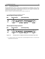
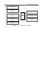
Processing Procedures for System Calls from Handlers................................................... 130
7.2
7.3
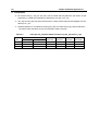
Calculating the Amount of RAM Used by the System ...................................................... 134
Stacks ................................................................................................................................... 135
7.1.1
System Calls from a Handler That Caused an Interrupt during Task Execution... 131
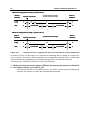
7.1.2
System Calls from a Handler That Caused an Interrupt during System Call
Processing.................................................................................................................................... 132
7.1.3
System Calls from a Handler That Caused an Interrupt during Handler Execution
133
7.3.1
Chapter 8
8.1
8.2
8.3
Sample Program Description ................................................................
...................................................................................
...................................................137
................... 137
Overview of Sample Program ............................................................................................. 138
Program Source Listing ...................................................................................................... 139
Configuration File................................................................................................................ 141
Chapter 9
9.1
System Stack and User Stack ..................................................................................... 135
Separate ROMs................................
ROMs................................................................
................................................................................................
.........................................................................
.........................................143
......... 143
How to Form Separate ROMs............................................................................................. 144
Index................................
Index ................................................................
................................................................................................
................................................................................................
..............................................................................
..............................................150
.............. 150
List of Figures
v
List of Figures
Figure 3.1
Figure 3.2
Figure 3.3
Figure 3.4
Figure 3.5
Figure 3.6
Figure 3.7
Figure 3.8
Figure 3.9
Figure 3.10
Figure 3.11
Figure 3.12
Figure 3.13
Figure 3.14
Figure 3.15
Figure 3.16
Figure 3.17
Figure 3.18
Figure 3.19
Figure 3.20
Figure 3.21
Figure 3.22
Figure 3.23
Figure 3.24
Figure 3.25
Figure 3.26
Figure 3.27
Figure 3.28
Figure 3.29
Figure 3.30
Figure 3.31
Figure 3.32
Figure 3.33
Figure 3.34
Figure 3.35
Figure 3.36
Figure 3.37
Figure 3.38
Figure 3.39
Figure 4.1
Figure 4.2
Figure 4.3
Relationship between Program Size and Development Period ............................... 10
Microcomputer-based System Example(Audio Equipment) .....................................11
Example System Configuration with Real-time OS(Audio Equipment)................. 12
Time-division Task Operation ................................................................................... 13
Task Execution Interruption and Resumption......................................................... 14
Task Switching ........................................................................................................... 14
Task Register Area ..................................................................................................... 15
Actual Register and Stack Area Management ......................................................... 16
System Call ................................................................................................................. 17
System Call Processing Flowchart ............................................................................ 18
Task Identification ..................................................................................................... 19
Task Status ................................................................................................................. 20
MR30 Task Status Transition.................................................................................... 21
Ready Queue (Execution Queue)............................................................................... 24
Task control block....................................................................................................... 26
Cyclic Handler/Alarm Handler Activation................................................................ 28
MR30 Structure .......................................................................................................... 30
Task Resetting ............................................................................................................ 32
Priority Change .......................................................................................................... 33
Ready Queue Management by rot_rdq System Call ................................................ 33
Suspending and Resuming a Task ............................................................................ 35
Wake-up Request Storage .......................................................................................... 36
Wake-up Request Cancellation.................................................................................. 36
Task Execution Control by the Eventflag ................................................................. 38
Exclusive Control by Semaphore............................................................................... 39
Semaphore Counter.................................................................................................... 39
Task Execution Control by Semaphore ..................................................................... 40
Mailbox........................................................................................................................ 41
Meaning of Message ................................................................................................... 41
Message queue Size.................................................................................................... 42
Interrupt process flow ................................................................................................ 44
Memorypool Management ......................................................................................... 45
pget_blk processing .................................................................................................... 47
rel_blk processing ....................................................................................................... 47
dly_tsk system call ..................................................................................................... 48
Timeout Processing .................................................................................................... 49
Cyclic Handler ............................................................................................................ 50
Cyclic Handler; TCY_ON Selected as Activity Status ............................................. 50
Cyclic Handler; TCY_INI_ON Selected as Activity Status...................................... 50
MR30 System Generation Detail Flowchart ............................................................ 57
Program Example....................................................................................................... 59
Configuration File Example ...................................................................................... 60
vi
List of Figures
Figure 4.4
Configurator Execution.............................................................................................. 61
Figure 4.5
System Generation ..................................................................................................... 61
Figure 5.1
Example Infinite Loop Task Described in C Language ........................................... 64
Figure 5.2
Example Task Terminating with ext_tsk() Described in C Language .................... 65
Figure 5.3
Example of OS-dependent Interrupt Handler.......................................................... 67
Figure 5.4
Example of OS-independent Interrupt Handler ...................................................... 68
Figure 5.5
Example Cyclic Handler Written in C Language..................................................... 69
Figure 5.6
Example Infinite Loop Task Described in Assembly Language .............................. 70
Figure 5.7
Example Task Terminating with ext_tsk Described in Assembly Language ......... 70
Figure 5.8
Example of OS-depend interrupt handler ................................................................ 72
Figure 5.9
Example of OS-independent Interrupt Handler of Specific Level .......................... 73
Figure 5.10
Example Handler Written in Assembly Language................................................... 74
Figure 5.11
Interrupt handler IPLs .............................................................................................. 76
Figure 5.12
Interrupt control in a System Call that can be Issued from only a Task ............... 77
Figure 5.13
Interrupt control in a System Call that can be Issued from a Task-independent . 78
Figure 5.14
C Language Startup Program (crt0mr.a30).............................................................. 88
Figure 5.15
Selection Allocation in C Language Startup Program ............................................. 92
Figure 6.1
The operation of the Configurator............................................................................116
Figure 7.1
Processing Procedure for a System Call a Handler that caused an interrupt during
Task Execution............................................................................................................................ 131
Figure 7.2
Processing Procedure for a System Call from a Handler that caused an interrupt
during System Call Processing .................................................................................................. 132
Figure 7.3
Processing Procedure for a system call from a Multiplex interrupt Handler ...... 133
Figure 7.4
System Stack and User Stack.................................................................................. 135
Figure 8.1
LED illumination Status ......................................................................................... 138
Figure 9.1
ROM separate ........................................................................................................... 146
Figure 9.2
Memory map ............................................................................................................. 148
List of Tables
vii
List of Tables
Table 2.1
Table 3.1
Table 3.2
Table 5.1
Table 5.2
Table 5.3
Table 6.1
Table 6.2
Table 6.3
Table 7.1
Table 8.1
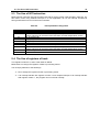
MR30 Specifications Overview ................................................................................... 7
System Calls Issuable from only Handlers.............................................................. 29
List of the system call can be issued from the task and handler ........................... 52
C Language Variable Treatment .............................................................................. 66
Interrupt Number Assignment................................................................................. 75
Interrupt and_ Dispatch Status Transition by dis_dsp and loc_cpu...................... 80
Numerical Value Entry Examples............................................................................ 96
Operators ................................................................................................................... 97
Fixed-Interrupt Causes and Vector Numbers ........................................................112
MR_RAM Method for Caluculating Size of MR_RAM Section............................. 134
Sample Program Function List .............................................................................. 138
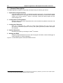
Chapter 1 User’s Manual Organization
2
Chapter 1 User’s Manual Organization
The MR30 User’s Manual consists of nine chapters and thee appendix.
•
•
•
•
•
•
•
•
Chapter 2 General Information
Outlines the objective of MR30 development and the function and position of the MR30.
Chapter 3 Introduction to MR30
Explains about the ideas involved in MR30 operations and defines some relevant terms.
Chapter 4 Applications Development Procedure Overview
Outlines the applications program development procedure for the MR30.
Chapter 5 Detailed Applications
Details the applications program development procedure for the MR30.
Chapter 6 Using Configurator
Describes the method for writing a configuration file and the method for using the configurator
in detail.
Chapter 7 Application Creation Guide
Presents useful information and precautions concerning applications program development
with MR30.
Chapter 8 Sample Program Description
Describes the MR30 sample applications program which is included in the product in the form
of a source file.
Chapter 9 Separate ROMs
Explains about how to Form Separate ROMs.
Chapter 2 General Information
4
Chapter 2 General Information
2.1 Objective of MR30 Development
In line with recent rapid technological advances in microcomputers, the functions of microcomputerbased products have become complicated. In addition, the microcomputer program size has increased.
Further, as product development competition has been intensified, manufacturers are compelled to
develop their microcomputer-based products within a short period of time.
In other words, engineers engaged in microcomputer software development are now required to develop larger-size programs within a shorter period of time. To meet such stringent requirements, it is
necessary to take the following considerations into account.
1. To enhance software recyclability to decrease the volume of software to be developed.
One way to provide for software recyclability is to divide software into a number of functional
modules wherever possible. This may be accomplished by accumulating a number of general-purpose subroutines and other program segments and using them for program development. In this method, however, it is difficult to reuse programs that are dependent on time or
timing. In reality, the greater part of application programs are dependent on time or timing.
Therefore, the above recycling method is applicable to only a limited number of programs.
2. To promote team programming so that a number of engineers are engaged in the development of one software package
There are various problems with team programming. One major problem is that debugging
can be initiated only when all the software program segments created individually by team
members are ready for debugging. It is essential that communication be properly maintained
among the team members.
3. To enhance software production efficiency so as to increase the volume of possible
software development per engineer.
One way to achieve this target would be to educate engineers to raise their level of skill.
Another way would be to make use of a structured descriptive assembler, C-compiler, or the
like with a view toward facilitating programming. It is also possible to enhance debugging efficiency by promoting modular software development.
However, the conventional methods are not adequate for the purpose of solving the problems. Under
these circumstances, it is necessary to introduce a new system named real-time OS 3
To answer the above-mentioned demand, Renesas has developed a real-time operating system,
tradenamed MR30, for use with the M16C/60 Series 16-bit one-chip microcomputers.
When the MR30 is introduced, the following advantages are offered.
1. Software recycling is facilitated.
When the real-time OS is introduced, timing signals are furnished via the real-time OS so that
programs dependent on timing can be reused. Further, as programs are divided into modules
called tasks, structured programming will be spontaneously provided.
That is, recyclable programs are automatically prepared.
2. Ease of team programming is provided.
When the real-time OS is put to use, programs are divided into functional modules called
tasks. Therefore, engineers can be allocated to individual tasks so that all steps from development to debugging can be conducted independently for each task.
Further, the introduction of the real-time OS makes it easy to start debugging some already
finished tasks even if the entire program is not completed yet. Since engineers can be allo3
OS:Operating System
2.1 Objective of MR30 Development
5
cated to individual tasks, work assignment is easy.
3. Software independence is enhanced to provide ease of program debugging.
As the use of the real-time OS makes it possible to divide programs into small independent
modules called tasks, the greater part of program debugging can be initiated simply by observing the small modules.
4. Timer control is made easier.
To perform processing at 10 ms intervals, the microcomputer timer function was formerly
used to periodically initiate an interrupt. However, as the number of usable microcomputer
timers was limited, timer insufficiency was compensated for by, for instance, using one timer
for a number of different processing operations.
When the real-time OS is introduced, however, it is possible to create programs for performing processing at fixed time intervals making use of the real-time OS time management function without paying special attention to the microcomputer timer function. At the same time,
programming can also be done in such a manner as to let the programmer take that numerous timers are provided for the microcomputer.
5. Software maintainability is enhanced
When the real-time OS is put to use, the developed software consists of small program modules called tasks. Therefore, increased software maintainability is provided because developed software maintenance can be carried out simply by maintaining small tasks.
6. Increased software reliability is assured.
The introduction of the real-time OS makes it possible to carry out program evaluation and
testing in the unit of a small module called task. This feature facilitates evaluation and testing
and increases software reliability.
7. The microcomputer performance can be optimized to improve the performance of microcomputer-based products.
With the real-time OS, it is possible to decrease the number of unnecessary microcomputer
operations such as I/O waiting. It means that the optimum capabilities can be obtained from
microcomputers, and this will lead to microcomputer-based product performance improvement.
6
Chapter 2 General Information
2.2 Relationship between TRON Specification and MR30
The TRON Specification is an abbreviation for The Real-time Operating system Nucleus specification.
It denotes the specifications for the nucleus of a real-time operating system. The TRON Project, which
is centered on TRON Specification design, is pushed forward under the leadership of Dr. Ken Sakamura at Faculty of Science, University of Tokyo.
As one item of this TRON Project, the ITRON Specification is promoted. The ITRON Specification is an
abbreviation for the Industrial TRON Specification. It denotes the real-time operating system that is
designed with a view toward establishing industrial real-time operating systems.
The ITRON Specification provides a number of functions to properly meet the application requirements.
In other words, ITRON systems require relatively large memory capacities and enhanced processing
capabilities. The µITRON Specification V.2.0 is the arranged version of the ITRON Specification for the
higher processing speed, and incorporated only a minimum of functions necessary. The µITRON
Specification V.2.0 can be said to be a subset of the ITRON Specification for the following reasons.
1. The system call time-out function is not incorporated.
2. Tasks, semaphores, and other objects can be generated only at the time of system generation.4 They cannot be generated after system startup.5
3. Only memorypools of a fixed-size can be handled. Memorypools of a variable-size cannot be handled.
4. Neither the system call exception management function nor the CPU exception management function is provided.
Currently stipulated are µITRON specifications V.3.0. The µITRON specifications V.3.0 provides enhanced connection functions by integrating µITRON specifications V.2.0 and ITRON specifications.
MR30 is a real-time operating system developed for the M16C/60 Series series of 16-bit microprocessors according to the µITRON specification.46 The µITRON specifications V.3.0 has its system calls
classified into level R, level S,level E, and level C.
MR30 implements all of level R and level S system calls and part of level E system calls among those
stipulated under µITRON specifications V.3.0.
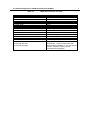
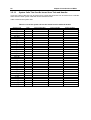
The MR30 specifications are outlined in Table 2.1.
4
Static object generation.
Dynamic object generation
6
MR30 V.1.00 conforms to µITRON Specifications V.3.0.
5
2.2 Relationship between TRON Specification and MR30
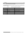
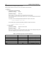
Table 2.1
MR30 Specifications Overview
Item
Target microprocessor
Maximum number of tasks
Task priorities
Maximum number of eventflags
Eventflag width
Maximum number of semaphores
Semaphore type
Maximum number of mailboxes
Message size
Buffer size of Mailbox
Maximum number of Fixed-size Memorypool
Maximum number of Variable-size Memorypool
Number of system calls
OS nucleus code size
OS nucleus data size
OS nucleus language
Specifications
M16C/60,30,20,10 series microcomputers
255
255
255
16 bit
255
Counter type
255
16 bit or 32 bit
more than 0 byte
255
1
61
Approx. 1.0K to 10.0K bytes
16bytes min., 11byte increment per task
(except stack) In addition, if you use timeout
function, increased 15byte per task.
C and Assembly language
7
8
Chapter 2 General Information
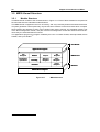
2.3 MR30 Features
The MR30 offers the following features.
1. Real-time operating system conforming to the µITORN Specification.
The MR30 is designed in compliance with the µITRON Specification which incorporates a
minimum of the ITRON Specification functions so that such functions can be incorporated into
a one-chip microcomputer. As the µITRON Specification is a subset of the ITRON Specification, most of the knowledge obtained from published ITRON textbooks and ITRON seminars
can be used as is.
Further, the application programs developed using the real-time operating systems conforming to the ITRON Specification can be transferred to the MR30 with comparative ease.
2. High-speed processing is achieved.
MR30 enables high-speed processing by taking full advantage of the microcomputer architecture.
3. Only necessary modules are automatically selected to constantly build up a system of
the minimum size.
The MR30 is supplied in the form of a M16C/60 series microcomputer objective library.
Therefore, the Linkage Editor LN30 functions are activated so that only necessary modules
are automatically selected from numerous MR30 functional modules to generate a system.
Thanks to this feature, a system of the minimum size is automatically generated at all times.
4. With the C-compiler NC30, it is possible to develop application programs in C language.
When the C-compiler NC30 is used, MR30 application programs can be developed in C language.Also note that an interface library is supplied on software disk to permit calling up the
MR30 functions in C language.
5. An upstream process tool named "Configurator" is provided to simplify development
procedures
A configurator is furnished so that various items including a ROM write form file can be created by giving simple definitions.
Therefore, there is no particular need to care what libraries must be linked.
Chapter 3 Introduction to MR30
10
Chapter 3 Introduction to MR30
3.1 Concept of Real-time OS
This section explains the basic concept of real-time OS.
3.1.1
Why Real-time OS is Necessary
In line with the recent advances in semiconductor technologies, the single-chip microcomputer ROM
capacity has increased. ROM capacity of 32K bytes.
As such large ROM capacity microcomputers are introduced, their program development is not easily
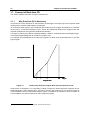
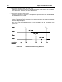
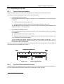
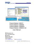
carried out by conventional methods. Fig.3.1 shows the relationship between the program size and
required development time (program development difficulty).
This figure is nothing more than a schematic diagram. However, it indicates that the development period increases exponentially with an increase in program size.
For example, the development of four 8K byte programs is easier than the development of one 32K
byte program.7
Development Period
4
8
16
32
Kbyte
Program Size
Figure 3.1
Relationship between Program Size and Development Period
Under these circumstances, it is necessary to adopt a method by which large-size programs can be
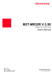
developed within a short period of time. One way to achieve this purpose is to use a large number of
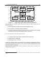
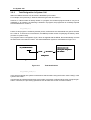
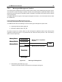
microcomputers having a small ROM capacity. Figure 3.2 presents an example in which a number of
microcomputers are used to build up an audio equipment system.
7
On condition that the ROM program burning step need not be performed.
3.1 Concept of Real-time OS
11
Key input
microcomputer
Remote control
microcomputer
LED illumination
microcomputer
Arbiter
microcomputer
Volume control
microcomputer
Figure 3.2
Monitor
microcomputer
Mechanical
control
microcomputer
Microcomputer-based System Example(Audio Equipment)
Using independent microcomputers for various functions as indicated in the above example offers the
following advantages.
1. Individual programs are small so that program development is easy.
2. It is very easy to use previously developed software.8
3. Completely independent programs are provided for various functions so that program
development can easily be conducted by a number of engineers.
On the other hand, there are the following disadvantages.
1. The number of parts used increases, thereby raising the product cost.
2. Hardware design is complicated.
3. Product physical size is enlarged.
Therefore, if you employ the real-time OS in which a number of programs to be operatedby a number of
microcomputers are placed under software control of one microcomputer, making it appear that the
programs run on separate microcomputers, you can obviate all the above disadvantages while retaining the above-mentioned advantages.
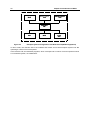
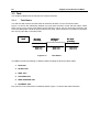
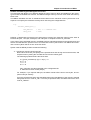
Figure 3.3 shows an example system that will be obtained if the real-time OS is incorporated in the
system indicated in Figure 3.2.
8
In the case presented in Figure 3.2 for instance, the remote control microcomputer can be used for other products without being
modified.
12
Chapter 3 Introduction to MR30
Key input
Task
Remote control
Task
LED illumination
Task
real-time
OS
Volume control
Task
Figure 3.3
Monitor
Task
Mechanical
control
Task
Example System Configuration with Real-time OS(Audio Equipment)
In other words, the real-time OS is the software that makes a one-microcomputer system look like
operating a number of microcomputers.
In the real-time OS, the individual programs, which correspond to a number of microcomputers used in
a conventional system, are called tasks.
3.1 Concept of Real-time OS
3.1.2
13
Operating Principles of Real-time OS
The real-time OS is the software that makes a one-microcomputer system look like operating a number
of microcomputers. You should be wondering how the real-time OS makes a one-microcomputer system function like a number of microcomputers.
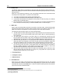
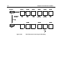
As shown in Figure 3.4 the real-time OS runs a number of tasks according to the time-division system.
That is, it changes the task to execute at fixed time intervals so that a number of tasks appear to be
executed simultaneously.
Key input
Task
Remote control
Task
LED
illumination
Task
Volume control
Task
Monitor
Task
Mechanical
control
Task
Time
Figure 3.4
Time-division Task Operation
As indicated above, the real-time OS changes the task to execute at fixed time intervals. This task
switching may also be referred to as dispatching (technical term specific to real-time operating systems). The factors causing task switching (dispatching) are as follows.
•
Task switching occurs upon request from a task.
•
Task switching occurs due to an external factor such as interrupt.
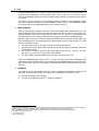
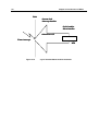
When a certain task is to be executed again upon task switching, the system resumes its execution at
the point of last interruption (See Figure 3.5).
14
Chapter 3 Introduction to MR30
Program execution
interrupt
Key input
Task
Program execution
resumed
During this interval, it
appears that the key input
microcomputer is haled.
Remote control
Task
Figure 3.5
Task Execution Interruption and Resumption
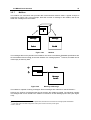
In the state shown in Figure 3.5, it appears to the programmer that the key input task or its microcomputer is halted while another task assumes execution control.
Task execution restarts at the point of last interruption as the register contents prevailing at the time of
the last interruption are recovered. In other words, task switching refers to the action performed to save
the currently executed task register contents into the associated task management memory area and
recover the register contents for the task to switch to.
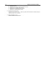
To establish the real-time OS, therefore, it is only necessary to manage the register for each task and
change the register contents upon each task switching so that it looks as if a number of microcomputers
exist (See Figure 3.6).
R0
R1
Actual
Register
PC
Real-time OS
Key input
Task
Remote control
Task
R0
R0
R1
R1
PC
PC
Register
Register
Figure 3.6
Task Switching
3.1 Concept of Real-time OS
15
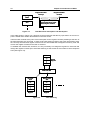
The example presented in Figure 3.1 indicates how the individual task registers are managed. In reality,
it is necessary to provide not only a register but also a stack area for each task.
Memory map
Register
R0
Remote control
Task
PC
SP
R0
Key input
Task
Stack
section
PC
SP
R0
LED illumination
Task
PC
SP
Real-time
OS
SP
Figure 3.7
SFR
Task Register Area
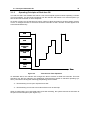
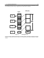
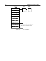
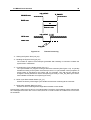
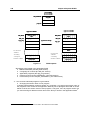
Figure 3.8 shows the register and stack area of one task in detail. In the MR30, the register of each task
is stored in a stack area as shown in Figure 3.8. This figure shows the state prevailing after register
storage.
16
Chapter 3 Introduction to MR30
SP
Register not stored
PC
FLG
FB
SB
A1
A0
Key input task
stack
R3
R2
Key input
Task
R1
SP
R0
Register stored
SFR
Figure 3.8
Actual Register and Stack Area Management
3.2 System Call
17
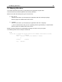
3.2 System Call
How does the programmer use the real-time OS in a program?
First, it is necessary to call up a real-time OS function from the program in some way or other. Calling a
real-time OS function is referred to as a system call. Task activation and other processing operations
can be initiated by such a system call (See Figure 3.9).
Key input
Task
Remote control
task
Real-time OS
System call
Figure 3.9
Task switching
System Call
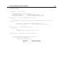
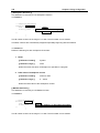
When application programs are to be written in C language, a system call is accomplished by making a
function call, as indicated below.
sta_tsk(ID_main,3);
If application programs are to be written in assembly language, a system call is accomplished by making an assembler macro call, as indicated below.
sta_tsk #ID_main,#3
18
Chapter 3 Introduction to MR30
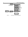
3.2.1
System Call Processing
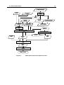
When a system call is issued, processing takes place in the following sequence.9
1. The current register contents are saved.
2. The stack pointer is changed from the task type to the real-time OS (system) type.
3. Processing is performed in compliance with the request made by the system call.
4. The task to be executed next is selected.
5. The stack pointer is changed to the task type.
6. The register contents are recovered to resume task execution.
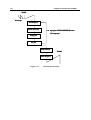
The flowchart in Figure 3.10 shows the process between system call generation and task switching.
Key input Task
Register Save
System call issuance
SP <= OS
Processing
Task Selection
Task => SP
LED illumination Task
Register Restore
Figure 3.10
9
System Call Processing Flowchart
A different sequence is followed if the issued system call does not evoke task switching.
3.2 System Call
3.2.2
19
Task Designation in System Call
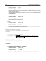
Within the MR30 real-time OS, each task is identified by ID number.
For example, the system says, "Start the task having the task ID number 1."
However, if a task number is directly written in a program, the resultant program would be very low in
readability. If, for instance, the following is entered in a program, the programmer is constantly required
to know what the No. 2 task is.
sta_tsk(2,1);
Further, if this program is viewed by another person, he/she does not understand at a glance what the
No. 2 task is. To avoid such inconvenience, the MR30 provides means of specifying the task by name
(function or symbol name).
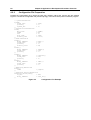
The program named "configurator cfg30 ,"which is supplied with the MR30, then automatically converts
the task name to the task ID number. This task identification system is schematized in Figure 3.11.
sta_tsk
sta_tsk(Task
_tsk(Task name)
Name
ID number
Starting the task
having the designated
ID number
Configurator
Program
Real-time OS
Figure 3.11
Task Identification
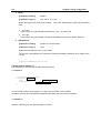
sta_tsk(ID_task,1);
In the above example, the system is instructed to start the task having the function name "task()" or the
symbol name "task:".
It should also be noted that task name-to-ID number conversion is effected at the time of program generation. Therefore, the processing speed does not decrease due to this conversion feature.
20
Chapter 3 Introduction to MR30
3.3 Task
This chapter explains how the real-time OS controls the tasks.
3.3.1
Task Status
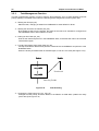
The real-time OS monitors the task status to determine whether or not to execute the tasks.
Figure 3.12 shows the relationship between key input task execution control and task status. When
there is a key input, the key input task must be executed. That is, the key input task is placed in the
execution (RUN) state. While the system waits for key input, task execution is not needed. In that situation, the key input task in the WAIT state.
Key input
Task
Key input
processing
RUN state
Figure 3.12
Waiting for
key input
WAIT state
Key input
processing
RUN state
Task Status
The MR30 controls the following six different states including the RUN and WAIT states.
1. RUN state
2. READY state
3. WAIT state
4. SUSPEND state
5. WAIT-SUSPEND state
6. DORMANT state
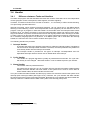
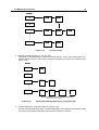
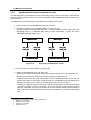
Every task is in one of the above six different states. Figure 3.13 shows task status transition.
3.3 Task
21
MPU execlusive right acquisition
READY state
RUN state
MPU execlusive right relinquishment
Entering the
WAIT state
WAIT state clear
WAIT state
SUSPEND state clear
request from other task
SUSPEND request
from other task
Forced
termination
request
from other
task
WAIT-SUSPEND
state
SUSPEND request
from other task
SUSPEND state
clear request
Forced termination
request from other task
WAIT state clear
request
SUSPEND
state
DORMANT
state
Task activation
Figure 3.13
MR30 Task Status Transition
1. RUN state
In this state, the task is being executed. Since only one microcomputer is used, it is natural
that only one task is being executed.
The currently executed task changes into a different state when any of the following conditions occurs.
♦
♦
♦
♦
♦
The task has normally terminated itself.10
The task has placed itself in the WAIT state.11
Due to interruption or other event occurrence, the interrupt handler has placed a different
task having a higher priority in the READY state.
The priority assigned to the task has been changed so that the priority of another READY
task is rendered higher.12
Due to interruption or other event occurrence, the priority of the task or a different READY
task has been changed so that the priority of the different task is rendered higher.13
When any of the above conditions occurs, rescheduling takes place so that the task having
the highest priority among those in the RUN or READY state is placed in the RUN state, and
the execution of that task starts.
10
Upon ext_tsk system call
Upon slp_tsk, tslp_tsk, dly_tsk, wai_flg, twai_flg, wai_sem, twai_sem, rcv_msg or trcv_msg system call.
12
Upon chg_pri system call.
13
Upon ichg_pri system call.
11
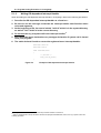
22
Chapter 3 Introduction to MR30
2. READY state
The READY state refers to the situation in which the task that meets the task execution conditions is still waiting for execution because a different task having a higher priority is currently
being executed.
When any of the following conditions occurs, the READY task that can be executed second
according to the ready queue 14 is placed in the RUN state.
♦
♦
♦
♦
A currently executed task has normally terminated itself.15
A currently executed task has placed itself in the WAIT state.16
A currently executed task has changed its own priority so that the priority of a different
READY task is rendered higher.17
Due to interruption or other event occurrence, the priority of a currently executed task has
been changed so that the priority of a different READY task is rendered higher.18
3. WAIT state
When a task in the RUN state requests to be placed in the WAIT state, it exits the RUN state
and enters the WAIT state. The WAIT state is usually used as the condition in which the completion of I/O device I/O operation or the processing of some other task is awaited.
The task goes into the WAIT state in one of the following ways.
♦
♦
♦
♦
♦
The task enters the WAIT state simply when the slp_tsk system call is issued.In this case,
the task does not go into the READY state until its WAIT state is cleared explicitly by
some other task.
The task enters and remains in the WAIT state for a specified time period when the
dly_tsk system call is issued. In this case, the task goes into the READY state when the
specified time has elapsed or its WAIT state is cleared explicitly by some other task.
When the wai_flg, wai_sem, or rcv_msg system call is issued, the task enters the WAIT
state and waits to be requested. In this case, the task moves into the READY state when
the request condition is met or its WAIT state is cleared explicitly by some other task.
The tslp_tsk, twai_flg, twai_sem, and trcv_msg system calls specify the time-outs for the
slp_tsk, wai_flg, wai_sem, and rcv_msg system calls. The system enters the wait state for
the wait condition specified in each system call. After the wait condition is met or the
specified time has elapsed, the task enters the executable state.
When the task enters the WAIT state and waits to be requested upon the issuance of the
wai_flg, twai_flg, wai_sem, twai_sem, rcv_msg or trcv_msg system call, it joins any of the
following queues depending on the request.
•
Eventflag Queue
•
Semaphore Queue
•
Mailbox Queue
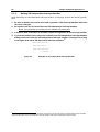
4. SUSPEND state
When the sus_tsk system call is issued from a task in the RUN state or the isus_tsk system
call is issued from a handler, the READY task designated by the system call or the currently
executed task enters the SUSPEND state. If a task in the WAIT state is placed in this situation,
it goes into the WAIT-SUSPEND state.
14
For the information on the ready queue,see the next chapter.
Upon ext_tsk system call.
16
Upon slp_tsk,tslp_tsk,dly_tsk,wai_flg, twai_flg, wai_sem, twai_sem or rcv_msg system call.
17
Upon chg_pri system call.
18
Upon ichg_pri system call.
15
3.3 Task
23
The SUSPEND state is the condition in which a READY task or currently executed task119 is
excluded from scheduling to halt processing due to I/O or other error occurrence. That is,
when the SUSPEND request is made to a READY task, that task is excluded from the execution queue.
Note that no queue is formed for the SUSPEND request. Therefore, the SUSPEND request
can only be made to the tasks in the RUN, READY, or WAIT state.20 If the SUSPEND request
is made to a task in the SUSPEND state, an error code is returned.
5. WAIT-SUSPEND
When the SUSPEND request is made to a task in the WAIT state, that task goes into the
WAIT-SUSPEND state. When the SUSPEND request is made to a task that is waiting for a
request made by the wai_flg, twai_flg, wai_sem, twai_sem, rcv_msg or trcv_msg system call,
that task remains in the request queue and simply goes into the WAIT- SUSPEND state.
When the wait condition for a task in the WAIT-SUSPEND state is cleared, that task goes into
the SUSPEND state. It is conceivable that the wait condition may be cleared, when any of the
following conditions occurs.
♦
♦
♦
♦
The task wakes up upon wup_tsk, or iwup_tsk system call issuance.
The task placed in the WAIT state by the dly_tsk or tslp_tsk system call wakes up after the
specified time elapse.
The request of the task placed in the WAIT state by the wai_flg , twai_flg, wai_sem,
twai_sem, rcv_msg or trcv_msg system call is fulfilled.
The WAIT state is forcibly cleared by the rel_wai or irel_wai system call
When the SUSPEND state clear request21 is made to a task in the WAIT-SUSPEND state,
that task goes into the WAIT state. Since a task in the SUSPEND state cannot request to be
placed in the WAIT state, status change from SUSPEND to WAIT-SUSPEND does not possibly occur.
6. DORMANT
This state refers to the condition in which a task is registered in the MR30 system but not
activated. This task state prevails when either of the following two conditions occurs.
♦
♦
The task is waiting to be activated.
The task is normally terminated22 or forcibly terminated.23
19
When a handler issued the isus_tsk system call to place a currently executed task in the SUSPEND state, status switching is
effected directly from RUN to SUSPEND. This is exceptional status change and should be kept in mind.
20
If the SUSPEND request is made to a task in the WAIT state, that task goes into the WAIT-SUSPEND state.
21
rsm_tsk or irsm_tsk system call
22
ext_tsk system call
23
ter_tsk system call
24
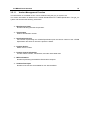
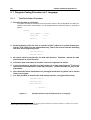
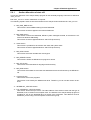
3.3.2
Chapter 3 Introduction to MR30
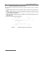
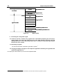
Task Priority and Ready Queue
In the real-time OS, several tasks may simultaneously request to be executed. In such a case, it is
necessary to determine which task the system should execute first.To properly handle this kind of
situation, the system organizes the tasks into proper execution priority and starts execution with a task
having the highest priority. To complete task execution quickly, tasks related to processing operations
that need to be performed immediately should be given higher priorities.
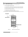
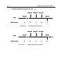
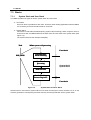
The MR30 permits giving the same priority to several tasks. To provide proper control over the READY
task execution order, the system generates a task execution queue called "ready queue." The ready
queue structure is shown in Figure 3.1424 The ready queue is provided and controlled for each priority
level. The first task in the ready queue having the highest priority is placed in the RUN state.25
Priority
1
TCB
2
3
TCB
TCB
n
TCB
TCB
Figure 3.14
24
25
TCB
Ready Queue (Execution Queue)
The TCB(task control block is described in the next chapter.)
The task in the RUN state remains in the ready queue.
3.3 Task
3.3.3
25
Task Control Block(TCB)
The task control block (TCB) refers to the data block that the real-time OS uses for individual task
status, priority, and other control purposes.
The MR30 manages the following task information as the task control block
•
Task connection pointer
Task connection pointer used for ready queue formation or other purposes.
•
Task status
•
Task priority
•
Task register information and other data26 storage stack area pointer(current SP register value)
•
•
•
•
•
Wake-up counter
Task wake-up request storage area.
Time-out counter or wait flag pattern
When a task is in a time-out wait state, the remaining wait time is stored; if in a flag wait state,
the flag's wait pattern is stored in this area.
Flag wait mode
This is a wait mode during eventflag wait.
Timer queue connection pointer
This area is used when using the timeout function. This area stores the task connection
pointer used when constructing the timer queue.
Flag wait pattern
This area is used when using the timeout function.
This area stores the flag wait pattern when using the eventflag wait system call with the timeout function (twai_flg). No flag wait pattern area is allocated when the eventflag is not used.
The task control block is schematized in Figure 3.15.
26
Called the task context
26
Chapter 3 Introduction to MR30
TCB
TCB
TCB
Task Connection pointer
Status
Priority
SP
Wake-up counter
Flag wait mode
Time-out counter
or
Flag wait pattern
Timer queue
Connection pointer
Flag wait pattern
Figure 3.15
This area is allocated only when
the timeout function is used.
Task control block
3.4 Handler
27
3.4 Handler
3.4.1
Difference between Tasks and Handlers
The tasks are program units that the MR30 executes and controls. Each task has its own independent
context (program counter, stack pointer, status register, and other registers).
Therefore, to transfer execution from one task to another27 , it is necessary to effect context switching.
This processing operation takes time.
Interrupt processing, which requires high-speed response, can be carried out by the MR30 without
effecting context switching. That is, the interrupted task context (registers) can be used as is to run a
program. This type of program is called the handler. As the handler uses the interrupted task context
(registers) as is, it is always necessary to save the interrupted task context into memory at the beginning of the handler, and put the saved context back into the original position when returning to the task.
To make a return from the interrupt handler, the ret_int system call should normally be used when written in assembly language.(See 5.2.2) However, if no MR30 system call is used within the interrupt
handler, the reit instruction can be used to make a return.(See 5.2.3)
The following handlers are provided.
1. Interrupt Handler
A program that starts upon hardware interruption is called the interrupt handler. The MR30 is
not concerned in interrupt handler activation. Therefore, the interrupt handler entry address is
to be directly written into the interrupt vector table.
The interrupt handler is provided for two types of interrupts: OS-independent and OSdependent interrupts. Refer to Section 5.5 for details about each interrupt.
2. Cyclic Handler
This handler is a program that starts cyclically at preselected time intervals. The cyclic handler activity is to be changed28 determine whether or not to validate a preset cyclic handler.
3. Alarm Handler
This handler starts at preselected times.
If a system time is reset (etc. set_tim () system call) to a tme before an Alarm Handler already
started, the Alarm Handler will never restart. If the system time is reset to a time after an
Alarm Handler starts, all Alarm Handler will never start.
The cyclic handler and alarm handler are called up by means of a subroutine call from the system clock
interrupt (timer interrupt) handler (See Figure 3.16). Therefore, the cyclic handler and alarm handler
function as part of the system clock interrupt handler. Note that the cyclic handler and alarm handler are
called up under the conditions whose state is the system clock interrupt priority level.
27
28
This transfer is called dispatching or switching
act_cyc system call
28
Chapter 3 Introduction to MR30
Task
System clock
interrupt handler
Cyclic handler
Alarm handler
Subroutine call
Timer interrupt
RTS
Figure 3.16
Cyclic Handler/Alarm Handler Activation
3.4 Handler
3.4.2
29
System Calls Exclusive for Handlers
In the MR30, the following system calls can be issued from the handlers only. Note, however, that the
ret_int system call is dedicated to the interrupt handler29 and therefore cannot be issued from the cyclic
handler or alarm handler.
Table 3.1
ichg_pri
irot_rdq
irel_wai
isus_tsk
irsm_tsk
iwup_tsk
iset_flg
isig_sem
isnd_msg
ista_tsk
ret_int
29
System Calls Issuable from only Handlers
System call name
Change Task Priority
Rotate Ready Queue
Release Task Wait
Suspend Task
Resume Task
Wakeup Task
Set EventFlag
Signal Semaphore
Send Message to Mailbox
Start Task
Return from Interrupt Handler
Function
Changes the task priority.
Rotates the task ready queue.
Forcibly clears the task WAIT state.
Puts a task into the SUSPEND state.
Resumes the suspended task.
Wakes up the waiting task.
Sets an eventflag.
Signal operation for a semaphore.
Sends a message.
Starts the task.
Return from the interrupt handler.
It isn't necessary to write this system call when specifying the interrupt handler as #pragma INTHANDLER in C language.
30
Chapter 3 Introduction to MR30
3.5 MR30 Kernel Structure
3.5.1
Module Structure
The MR30 kernel consists of the modules shown in Figure 3.17. Each of these modules is composed of
functions that exercise individual module features.
The MR30 kernel is supplied in the form of a library, and only necessary features are linked at the time
of system generation. More specifically, only the functions used are chosen from those which comprise
these modules and linked by means of the Linkage Editor LN30. However, the scheduler module, part
of the task management module, and part of the time management module are linked at all times because they are essential feature functions.
The applications program is a program created by the user. It consists of tasks, interrupt handler, alarm
handler, and cyclic handler.30
User Module
Application Program
Task
Management
Mailbox
Semaphore
Task-dependent
synchronization
Eventflag
Memorypool
Management
Scheduler
Time
Management
Version
Management
Interrupt
Management
M16C Microcomputer
Figure 3.17
30
For details, See 3.5.10.
MR30 kernel
MR30 Structure
Hardware
3.5 MR30 Kernel Structure
3.5.2
31
Module Overview
The MR30 kernel modules are outlined below.
•
•
•
•
•
•
•
Scheduler
Forms a task processing queue based on task priority and controls operation so that the
high-priority task at the beginning in that queue (task with small priority value) is executed.
Task Management Module
Exercises the management of various task states such as the RUN, READY, WAIT, and
SUSPEND state.
Task Synchronization Module
Accomplishes inter-task synchronization by changing the task status from a different task.
Interrupt Management Module
Makes a return from the interrupt handler.
Time Management Module
Sets up the system timer used by the MR30 kernel and starts the user-created alarm handler31 and cyclic handler.32.
Version Management Module
Reports the MR30 kernel version number or other information.
Sync/Communication Module
This is the function for synchronization and communication among the tasks. The following
three functional modules are offered.
♦
Eventflag
Checks whether the flag controlled within the MR30 is set up and then determines whether
or not to initiate task execution. This results in accomplishing synchronization between
tasks.
♦
Semaphore
Reads the semaphore counter value controlled within the MR30 and then determines
whether or not to initiate task execution. This also results in accomplishing synchronization
between tasks.
♦
Mailbox
Provides inter-task data communication by delivering the first data address.
•
31
32
Memorypool Management Module
Provides dynamic allocation or release of a memory area used by a task or a handler.
This handler actuates once only at preselected times.
This handler periodically actuates.
32
Chapter 3 Introduction to MR30
3.5.3
Task Management Function
The task management function is used to perform task operations such as task start/stop and task
priority updating. The MR30 kernel offers the following task management function system calls.
•
•
•
•
Starting the Task (sta_tsk)
Starts the task, changing its status from DORMANT to either READY or RUN.
Starting the Task from the handler (ista_tsk)
By activating a task from the handler, the status of the task to be activated is changed from
the DORMANT state to either READY or RUN.
Ending Its Own Task (ext_tsk)
Ends its own task and places it in the DORMANT state, so that this task will not be executed
until activated again.
Forcibly Terminating Some Other Task (ter_tsk)
Forcibly terminates a different task placed in a state other than DORMANT and places it in the
DORMANT state.
When the forcibly terminated task is activated again, it acts as if it is reset (See Figure 3.18).
TaskA
TaskB
ter_tsk(B)
ter_tsk(B)
Terminated
sta_tsk(B)
sta_tsk(B)
Reseting TaskB
Figure 3.18
•
Task Resetting
Changing the Task Priority (chg_pri, ichg_pri)
Changes the task priority, and if the task is in the READY or RUN state, updates the ready
queue also (See Figure 3.19).
3.5 MR30 Kernel Structure
33
Priority
TCB
TCB
3
TCB
TCB
n
TCB
TCB
1
2
Figure 3.19
•
TCB
Priority Change
Rotating the Ready Queue (rot_rdq, irot_rdq)
This system call establishes the TSS (time-sharing system). That is, if the ready queue is rotated at regular intervals, round robin scheduling required for the TSS is accomplished (See
Figure 3.20).
Priority
1
TCB
2
3
TCB
TCB
n
TCB
TCB
TCB
Move the end of the queue
Figure 3.20
•
Ready Queue Management by rot_rdq System Call
Forcibly Clearing the Task WAIT State (rel_wai, irel_wai)
Forcibly clears the task WAIT state. The WAIT state tasks to be cleared by this system call are
those which have entered the WAIT state under the following conditions.
34
Chapter 3 Introduction to MR30
♦
♦
♦
♦
♦
•
•
Waiting for timeout
Waiting for by the slp_tsk system call(+With Timeout).
Waiting for the eventflag(+With Timeout).
Waiting for the semaphore(+With Timeout).
Waiting for a message(+With Timeout).
Acquiring Its Own ID (get_tid)
Acquires its own task ID number. When this system call is issued from a handler, 0(zero) is
obtained instead of the ID number.
Refer Task Status (ref_tsk)
Checks the status of the target task.
3.5 MR30 Kernel Structure
3.5.4
35
Synchronization functions attached to task
The task-dependent synchronization functions attached to task is used to accomplish synchronization
between tasks by placing a task in the WAIT, SUSPEND, or WAIT-SUSPEND state or waking up a
WAIT state task.
The MR30 offers the following task incorporated synchronization system calls.
•
•
Placing a Task in the SUSPEND State (sus_tsk, isus_tsk)
Restarting a Task Placed in SUSPEND State (rsm_tsk, irsm_tsk)
Forcibly suspends or resumes task execution. If a READY task is forced to wait, it enters the
SUSPEND state. If a WAITING state task is forcibly suspended, it enters the WAITSUSPEND state (See Figure 3.21).
READY state
WAIT state
sus_tsk
sus_tsk
rsm_tsk
rsm_tsk
sus_tsk
sus_tsk
rsm_tsk
rsm_tsk
isus_tsk
isus_tsk
irsm_tsk
irsm_tsk
isus_tsk
isus_tsk
irsm_tsk
irsm_tsk
SUSPEND state
Figure 3.21
•
•
WAIT-SUSPEND state
Suspending and Resuming a Task
Placing a Task in the WAIT State (slp_tsk,tslp_tsk)
Waking up wait state task (wup_tsk, iwup_tsk)
Wakes up a task that has been placed in a WAIT state by the slp_tsk or tslp_tsk system call.
No task can be waked up unless they have been placed in a WAIT state by.33
If tasks that have been placed in a WAIT state for other conditions than the slp_tsk, tslp_tsk
system call or tasks in other states except one that is in a DORMANT state are waked up by
the iwup_tsk system call, it results in only wakeup requests being accumulated.
Therefore, if a wakeup request is issued for a task in executing state, for example, that wakeup request is stored in memory temporarily. Then when the task in that executing state is
placed in a wait state by the slp_tsk system call, the accumulated wakeup request becomes
valid, so the task is executed continuously without being placed in a wait state. (See Figure
3.22).
33
Tasks waiting under the following conditions will not be waked up.
♦ Waiting for the eventflag
♦ Waiting for the semaphore
♦ Waiting for the message
♦ Waiting for timeout
36
Chapter 3 Introduction to MR30
•
Canceling a Task Wake-up Request (can_wup)
Clears the stored wake-up reques.(See Figure 3.23).
wup_tsk
wup_tsk
Task
Wake-up count
0
slp_tsk
slp_tsk
0
1
2
wup_tsk
wup_tsk
can_wup
can_wup
slp_tsk
slp_tsk
0
Figure 3.23
1
Wake-up Request Storage
wup_tsk
wup_tsk
Wake-up count
wup_tsk
wup_tsk
slp_tsk
slp_tsk
Figure 3.22
Task
wup_tsk
wup_tsk
slp_tsk
slp_tsk
0
1
0
Wake-up Request Cancellation
0
3.5 MR30 Kernel Structure
3.5.5
37
Eventflag
The eventflag is an internal facility of MR30 that is used to synchronize the execution of multiple tasks.
The eventflag uses a flag wait pattern and a 16-bit pattern to control task execution. A task is kept waiting until the flag wait conditions set are met.
The MR30 kernel offers the following eventflag system calls.
•
•
•
•
•
Setting the Eventflag (set_flg, iset_flg)
Sets the eventflag so that a task waiting the eventflag is released from the WAIT state.
Clearing the Eventflag (clr_flg)
Clearing the Eventflag.
Waiting for eventflag (wai_flg, twai_flg)
Waits until the eventflag is set to a certain pattern. There are three modes as listed below in
which the eventflag is waited for.
♦
AND wait
Waits until all specified bits are set.
♦
OR wait
Waits until any one of the specified bits is set
♦
Clear specification
Clears the flag when the AND wait or OR wait condition is met.
Getting eventflag (pol_flg)
Examines whether the eventflag is in a certain pattern. In this system call, tasks are not
placed in a wait state.
Refer Eventflag Status (ref_flg)
Checks the existence of the bit pattern and wait task for the target eventflag.
Figure 3.24 shows an example of task execution control by the eventflag using the wai_flg and set_flg
system calls.
The eventflag has a feature that it can wake up multiple tasks collectively at a time.
In Figure 3.24, there are six tasks linked one to another, task A to task F. When the flag pattern is set to
0xF by the set_flg system call, the tasks that meet the wait conditions are removed sequentially from
the top of the queue. In this diagram, the tasks that meet the wait conditions are task A, task C, task E,
and task F. Out of these tasks, task A, task C, and task E are removed from the queue.
However, since task E is waiting in clear specification, the flag is cleared when task E is remove from
the queue. Therefore, task F is not removed from the queue.
38
Chapter 3 Introduction to MR30
TaskA
Flag queue
TaskB
TaskC
TaskD
TaskE
TaskF
0xFF
AND
0x0F
AND
0xFF
AND+CLR
0xFF
OR+CLR
0x0F
OR
Flag pattern
0
Wait pattern
Wait mode
0x0F
OR
set_flg
set_flg
TaskB
TaskD
TaskF
Flag pattern
0x0F
Flag pattern
0x0F
0
Figure 3.24
Task Execution Control by the Eventflag
3.5 MR30 Kernel Structure
3.5.6
39
Semaphore
The semaphore is a function executed to coordinate the use of devices and other resources to be
shared by several tasks in cases where the tasks simultaneously require the use of them. When, for
instance, four tasks simultaneously try to acquire a total of only three communication lines as shown in
Figure 3.25, communication line-to-task connections can be made without incurring contention.
Task
Communication
Line
Communication
Line
Task
Communication
Line
Task
Semaphore
Task
Figure 3.25
Exclusive Control by Semaphore
The semaphore has an internal semaphore counter. In accordance with this counter, the semaphore is
acquired or released to prevent competition for use of the same resource.(See Figure 3.26).
Acquired
Task
Returned after use
Figure 3.26
Semaphore Counter
The MR30 kernel offers the following semaphore synchronization system calls.
•
Signaling the Semaphore (sig_sem, isig_sem)
Sends a signal to the semaphore. This system call wakes up a task that is waiting for the
semaphores service, or increments the semaphore counter by 1 if no task is waiting for the
semaphores service.
40
Chapter 3 Introduction to MR30
•
•
•
Acquiring the Semaphore (wai_sem, twai_sem)
Waits for the semaphores service. If the semaphore counter value is 0 (zero), the semaphore
cannot be acquired. Therefore, the WAIT state prevails.
Acquiring the Semaphore (preq_sem)
Acquires the semaphore. If there is no semaphore to acquire, an error code is returned and
the WAIT state does not prevail.
Refer Semaphore Status (ref_sem)
Checks the status of the target semaphore. Checks the count value and existence of the wait
task for the target semaphore.
Figure 3.27 shows example task execution control provided by the wai_sem and sig_sem
system calls.
wai_sem
Task
sig_sem
wai_sem
Task
wai_sem
Task
wai_sem
Task
WAIT state
Semaphore
Counter
3
Figure 3.27
2
1
0
x
Task Execution Control by Semaphore
0
3.5 MR30 Kernel Structure
3.5.7
41
Mailbox
The mailbox is a mechanism that provides data communication between tasks. A typical example is
presented in Figure 3.28. In this example, after task A sends a message in the mailbox, task B can
obtain the message from the mailbox.
Message
Message
TaskA
TaskB
Figure 3.28
Mailbox
The messages that can be placed into this mailbox are 16-bit or 32-bit data. Standard specifications are
such that MR30 uses this data as the start address of a message packet.34 However, this data can be
used simply as ordinary data.35
Data
1
2
Message
Packet
Figure 3.29
Meaning of Message
The mailbox is capable of storing messages. Stored messages are retrieved on the FIFO basis.36
However, the number of messages that can be stored in the mailbox is limited. The maximum number
of messages that can be stored in the mailbox is referred to as the Message queue size (See Figure
3.30).
34
According to the standard stated in ITRON Specification,this data is to be used as the message packet first address.
In this case, Cast to the data of argument of the system call to convert into pointer types.
36
First in, first out.
35
42
Chapter 3 Introduction to MR30
Message queue
Message
Size
Message
Message
Message
Figure 3.30
Message queue Size
The MR30 kernel offers the following mailbox system calls.
•
•
•
•
Transmitting a Message (snd_msg, isnd_msg)
Sends a message or puts a message into the mailbox.
Receiving a Message (rcv_msg, trcv_msg)
Receives a message or obtains a message from the mailbox. If the message is not in the
mailbox, the WAIT state prevails until the message is put in the mailbox.
Receiving a Message (prcv_msg)
Receives a message. This system call differs from the rcv_msg system call in that the former
returns an error code without incurring the WAIT state if the message is not found in the mailbox.
Refer Mailbox Status (ref_mbx)
Checks the existence of tasks waiting for messages to enter the target mailbox, and checks
the first message in the mailbox.
3.5 MR30 Kernel Structure
3.5.8
43
Interrupt Management Function
The interrupt management function provides a function to process requested external interrupts in real
time.
The interrupt management system calls provided by the MR30 kernel include the following:
•
Returning from interrupt handler (ret_int)
The ret_int system call activates the scheduler to switch over tasks as necessary when returning from the interrupt handler.
When using the C language,37, this function is automatically called at completion of the handler function. In this case, therefore, there is no need to invoke this system call.
•
•
Disabling interrupts and task dispatch (loc_cpu)
The loc_cpu system call disables OS-dependent external interrupts and task dispatch.
Enabling interrupts and task dispatch (unl_cpu)
The (unl_cpu) system call enables external interrupts and task dispatch. Therefore, this system call re-enables the interrupts and task dispatch that have been disabled by the loc_cpu
system call.
Figure 3.31 shows an interrupt processing flow. Processing a series of operations from task selection to
register restoration is called a "scheduler.".
37
In the case that the interruput handler is specified by "#pragma INTHANDLER".
44
Chapter 3 Introduction to MR30
TaskA
Interrupt
Save Registers
Handler Processing
#pragma INTHANDLER Declare
(C language)
iwup_tsk
iwup_tsk
ret_int
ret_int
Task Selection
TaskB
Restore Registers
Figure 3.31
Interrupt process flow
3.5 MR30 Kernel Structure
3.5.9
45
Memorypool Management Function
The memorypool management function provides system memory space (RAM space) dynamic control.
This function is used to manage a specific memory area (memorypool), dynamically obtain memory
blocks from the memorypool as needed for tasks or handlers, and release unnecessary memory blocks
to the memorypool.
The MR30 supports two types of memorypool management functions, one for fixed-size and the other
for variable-size.
Fixed-size Memorypool Management Function
You specify memory block size using configuration file.
The MR30 kernel offers the following Fixed-size memorypool management system calls.
•
Acquiring a Memory Block (pget_blf)
•
Releasing a Memory Block (rel_blf)
As shown in Figure 3.32, memory block 3 in the memorypool is passed to task C upon memory block
acquisition request from task C. It is presumed in this case that memory blocks 1 and 2 are used by
tasks A and B, respectively
Memory Block 1:
Used by TaskA
Memory Block 2:
Used by TaskB
Memory block acquisition
request
TaskC
Memory Block 3:
Memory block acquisition
Unused area
Memorypool
Figure 3.32
•
Memorypool Management
Refer Memorypool Status (ref_mpf)
Checks the number and size of free blocks in the target memorypool.
46
Chapter 3 Introduction to MR30
Variable-size Memorypool Management Function
The technique that allows you to arbitrary define the size of memory block acquirable from the memorypool is termed Variable-size scheme. The MR30 manages memory in terms of four fixed-size memory
block sizes.
The MR30 calculates the size of individual blocks based on the maximum memory block size to be
acquired. You specify the maximum memory block size using the configuration file.
e.g.
variable_memorypool[]{
max_memsize
= 400; <---- Maximum size
heap_size
= 5000;
};
Defining a variable-size memorypool as shown above causes four fixed-size memory block sizes to
become 56 bytes, 112 bytes, 224 bytes, and 448 bytes in compliance with max_memsize.
In the case of user-requested memory, the MR30 performs calculations based on the specified size and
selects and allocates the optimum one of four fixed-size memory block sizes. The MR30 cannot allocate a memory block that is not one of the four sizes.
System calls the MR30 provides include the following.
•
Acquiring a memory block (pget_blk)
Round off a block size you specify to the optimal block size among the four block sizes, and
acquires memory having the rounded-off size from the memorypool.
The following equations define the block sizes:
a = (((max_memsize+(X-1))/ X × 8)+1) × 8
b=a×2
c=a×4
d=a×8
max_memsize: the value specified in the configuration file
X: data size for block control (8 byte)
For example, if you request 200-byte, the MR30 rounds off the size to 244 bytes, and acquires 244-byte memory.
If memory acquirement goes well, the MR30 returns the first address of the memory acquired
along with the error code "E_OK". If memory acquirement fails, the MR30 returns the error
code "E_TMOUT".
3.5 MR30 Kernel Structure
47
200 bytes
TaskA
Rounding
Memorypool
pget_blk
pget_blk
200 bytes
224 bytes
Figure 3.33
•
pget_blk processing
Releasing a Memory block (rel_blk)
Release a acquired memory block by pget_blk system call.
TaskA
Memorypool
Memorypool
rel_blk
rel_blk
top of
address
Figure 3.34
•
rel_blk processing
Refer Memorypool Status (ref_mpl)
Checks the total free area of the memorypool, and the size of the maximum free area that can
immediately be acquired.
48
Chapter 3 Introduction to MR30
3.5.10
Time Management Function
The time management function provides system time management, time reading38, time setup39, and
the functions of the alarm handler, which actuates at preselected times, and the cyclic handler, which
actuates at preselected time intervals.
The MR30 kernel makes an exclusive use of one M16C/60 Series microcomputer hardware timer as
the system timer. The configuration file is used to determine which timer is to be employed as the system timer.
The MR30 kernel offers the following time management system calls.
•
Placing a task in wait state for certain time (dly_tsk)
Keeps a task waiting for a certain time.Figure 3.35 shows an example in which task execution
is kept waiting for 10 ms by the dly_tsk system call.
dly_tsk(10)
Task
10ms
Figure 3.35
•
dly_tsk system call
Specifying a timeout value in the wait state causes the MR30 to switch to a fixed wait-time
status.
You can specify a timeout in a system call for switching the task to the wait state.40 The system calls are named tslp_tsk, twai_flg, twai_sem, and trcv_msg. If the conditions for exiting
the wait state are not satisfied prior to the specified timeout time elapsing, error code
E_TMOUT is returned and the wait state is cancelled. If the conditions for exiting the wait
state are satisfied, error code E_OK is returned. (See Figure 3.36 )
The MR30 system clock is used as the reference time for the timeout.
38
get_tim system call
set_tim system call
40
Cancel forced wait state.
39
3.5 MR30 Kernel Structure
49
tslp_tsk(50)
tslp_tsk(50)
E_TMOUT
READY state
WAIT state
50
Timeout value
tslp_tsk(50)
tslp_tsk(50)
RUN state
E_OK
WAIT state
iwup_tsk
iwup_tsk
Figure 3.36
•
•
•
•
•
Timeout Processing
Setting the System Time (set_tim)
Reading the System Time (get_tim)
The number of system clock interrupts generated after resetting is counted to indicate the
system time in 48-bit data.
Controlling the Cyclic Handler Activity (act_cyc)
The cyclic handler is a program running at fixed time intervals (See Figure 3.37). It cyclically
actuates according to the system clock interrupt count. For cyclic handler control purposes, its
activity status is specified by the system call. For example, TCY_ON may be selected to
change the activity status from OFF to ON (See Figure 3.38), or TCY_INI_ON may be selected to initialize the handler count (See Figure 3.39).
Refer Cycle Start Handler Status (ref_cyc)
Checks the activity of the target cycle handler and the time remaining till the next start.
Refer Alarm Handler Status (ref_alm)
Checks the time remaining till the target alarm handler is next started.
Note that the system timer function is not indispensable. Therefore, if the following system calls and the
time management function are not to be used, there is no need to make an exclusive use of one timer
for the MR30.
50
Chapter 3 Introduction to MR30
1. System clock setup/reading
41
2. Cyclic handler
3. Alarm handler
4. dly_tsk system call
5. system call with Timeout
Figure 3.37
TCY_OFF
Figure 3.38
Cyclic Handler
act_cyc
act_cyc
TCY_ON
Cyclic Handler; TCY_ON Selected as Activity Status
TCY_OFF
act_cyc
act_cyc
TCY_ON
TCY_INI_ON
Figure 3.39
41
set_tim, get_tim system call
Cyclic Handler; TCY_INI_ON Selected as Activity Status
3.5 MR30 Kernel Structure
3.5.11
51
Version Management Function
The information on the MR30 version can be obtained using the get_ver system call.
The version information is obtained in the format standardized in the TRON Specification. The get_ver
system call furnishes the following information.
•
•
•
•
•
•
•
Manufacturer Name
Number indicating Renesas Corporation.
Type Number
Product identification number.
Specification Version
The number representing the µITRON Specification plus the version number of the µITRON
Specification document on which the product is based.
Product Version
MR30 version number.
Product Control Information
Product release number, release date, and other associated data.
MPU Information
Number representing the M16C/80 Series Microcomputer.
Variation Descriptor
Number of the function set available for use with the MR30.
52
Chapter 3 Introduction to MR30
3.5.12
System Calls That Can Be Issued from Task and Handler
There are system calls that can be issued from a task and those that can be issued from a handler
while there are other system calls that can be issued from both.
Table 3.2 lists those system calls.
Table 3.2 List of the system call can be issued from the task and handler
System Call
sta_tsk
ista_tsk
ext_tsk
ter_tsk
dis_dsp
ena_dsp
chg_pri
ichg_pri
rot_rdq
irot_rdq
rel_wai
irel_wai
get_tid
ref_tsk
sus_tsk
isus_tsk
rsm_tsk
irsm_tsk
slp_tsk
tslp_tsk
dly_tsk
wup_tsk
iwup_tsk
can_wup
set_flg
iset_flg
clr_flg
wai_flg
twai_flg
pol_flg
ref_flg
Task
Ο
×
Ο
Ο
Ο
Ο
Ο
×
Ο
×
Ο
×
Ο
Ο
Ο
×
Ο
×
Ο
Ο
Ο
Ο
×
Ο
Ο
×
Ο
Ο
Ο
Ο
Ο
Interrupt Handler
×
Ο
×
×
×
×
×
Ο
×
Ο
×
Ο
Ο
Ο
×
Ο
×
Ο
×
×
×
×
Ο
Ο
×
Ο
Ο
×
×
Ο
Ο
Cyclic Handler
×
Ο
×
×
×
×
×
Ο
×
Ο
×
Ο
Ο
Ο
×
Ο
×
Ο
×
×
×
×
Ο
Ο
×
Ο
Ο
×
×
Ο
Ο
Alarm Handler
×
Ο
×
×
×
×
×
Ο
×
Ο
×
Ο
Ο
Ο
×
Ο
×
Ο
×
×
×
×
Ο
Ο
×
Ο
Ο
×
×
Ο
Ο
3.5 MR30 Kernel Structure
System Call
sig_sem
isig_sem
wai_sem
twai_sem
preq_sem
ref_sem
snd_msg
isnd_msg
rcv_msg
trcv_msg
prcv_msg
ref_mbx
pget_blf
rel_blf
ref_mpf
pget_blk
rel_blk
ref_mpl
ret_int
loc_cpu
unl_cpu
set_tim
get_tim
act_cyc
ref_cyc
ref_alm
get_ver
vrst_msg
vrst_blf
vrst_blk
42
Task
Ο
×
Ο
Ο
Ο
Ο
Ο
×
Ο
Ο
Ο
Ο
Ο
Ο
Ο
Ο
Ο
Ο
×
Ο
Ο
Ο
Ο
Ο
Ο
Ο
Ο
Ο
Ο
Ο
53
Interrupt Handler
×
Ο
×
×
Ο
Ο
×
Ο
×
×
Ο
Ο
Ο
Ο
Ο
×
×
Ο
Ο42
×
×
Ο
Ο
Ο
Ο
Ο
Ο
×
×
×
Cyclic Handler
×
Ο
×
×
Ο
Ο
×
Ο
×
×
Ο
Ο
Ο
Ο
Ο
×
×
Ο
×
×
×
Ο
Ο
Ο
Ο
Ο
Ο
×
×
×
The System Call can't be issued from the Interrupt Handler in C language.
Alarm Handler
×
Ο
×
×
Ο
Ο
×
Ο
×
×
Ο
Ο
Ο
Ο
Ο
×
×
Ο
×
×
×
Ο
Ο
Ο
Ο
Ο
Ο
×
×
×
Chapter 4 Applications Development
Procedure Overview
56
Chapter 4 Applications Development Procedure Overview
4.1 General Description
The MR30 application programs are generally developed using the following procedures.
1. Applications Program Coding
Code application programs in C or assembly language. At this time, copy the sample startup
program "crt0mr.a30" or "start.a30" from the directory indicated by the environment variable
"LIB30" to the current directory.43 Further, if necessary, modify the startup program and the
section definition file.
2. Configuration File Preparation
Using the editor, prepare the configuration file in which the task entry address, stack size, and
the like are defined.
3. Configurator Execution
Using the configuration file, create the system data definition files (sys_rom.inc and
sys_ram.inc), include files (mr30.inc and id.h), and system generation procedure description
file (makefile).
4. System Generation
Generate the system by executing the make44 command.
5. Writing into ROM
Using the prepared ROM write form file, write the program into ROM, or allow the debugger to
read the program to conduct debugging.
Figure 4.1 shows MR30 System Generation Detail Flowchart.
43
44
The standard startup programs "crt0mr.a30" and "start.a30" are in the directory indicated by the environmentr variable "LIB30".
The make command comes the UNIX standard and UNIX compatible.
4.1 General Description
57
Configuration file
C standard
header file
MR30 include file
mr30.h
Configurator
cfg30
Include file
id.h
Include file
mr30.inc
Application
include file
Application
C source
Application
Assembler source
System data definition file
sys_ram.inc, sys_rom.inc
Startup program
start.a30, crt0mr.a30
C compiler
nc30
Jamp table file
mrtable.a30
Relocatable Assembler
as30
Create Jamp table utility
mkmrtbl
Systemcall
file ( .mrc )
C standard
Library
MR30
Application
object
Library
Linkage Editor
ln30
Absolute
module
Load module converter
lmc30
ROM write format
Figure 4.1
MR30 System Generation Detail Flowchart
58
Chapter 4 Applications Development Procedure Overview
4.2 Development Procedure Example
This chapter outlines the development procedures on the basis of a typical MR30 application example.
4.2.1
Applications Program Coding
Figure 4.2 shows a program that simulates laser beam printer operations. Let us assume that the file
describing the laser beam printer simulation program is named lbp.c. This program consists of the
following three tasks and one interrupt handler.
•
Main Task
•
Image expansion task
•
Printer engine task
•
Centronics interface interrupt handler
This program uses the following MR30 library functions.
•
•
•
•
•
sta_tsk()
Starts a task. Give the appropriate ID number as the argument to select the task to be activated. When the id.h file, which is generated by the configurator, is included, it is possible to
specify the task by name (character string).45
wai_flg()
Waits until the eventflag is set up. In the example, this function is used to wait until one page
of data is entered into the buffer via the Centronics interface.
wup_tsk()
Wakes up a specified task from the WAIT state. This function is used to start the printer engine task.
slp_tsk()
Causes a task in the RUN state to enter the WAIT state. In the example, this function is used
to make the printer engine task wait for image expansion.
iset_flg()
Sets up the eventflag. In the example, this function is used to notify the image expansion task
of the completion of one-page data input.
At this time, make sure that the startup program "crt0mr.a30" and section definition file
"c_sec.inc" are copied to the current directory. For example,
> copy %LIB30%\crt0mr.a30 .
> copy %LIB30%\c_sec.inc .
45
The configurator converts the ID number to the associated name(character string) in accordance with the information entered
int the configuration file.
4.2 Development Procedure Example
59
#include <mr30.h>
#include "id.h"
void main() /* main task */
{
printf("LBP start simulation \n");
sta_tsk(ID_idle,1);
/* activate idle task */
sta_tsk(ID_image,1);
/* activate image expansion task */
sta_tsk(ID_printer,1); /* activate printer engine task */
}
void image() /* activate image expansion task */
{
while(1){
wai_flg(&flgptn,ID_pagein,waiptn,TWF_ANDW+TWF_CLR);/* wait for 1page input */
printf(" bit map expansion processing \n");
wup_tsk(ID_printer);
/* wake up printer engine task */
}
}
void printer() /* printer engine task */
{
while(1){
slp_tsk();
printf(" printer engine operation \n");
}
}
void sent_in() /* Centronics interface handler */
{
/* Process input from Centronics interface */
if ( /* 1-page input completed */ )
iset_flg(ID_pagein,setptn);
}
Figure 4.2
Program Example
60
Chapter 4 Applications Development Procedure Overview
4.2.2
Configuration File Preparation
Prepare the configuration file in which the task entry address, stack size, and the like are defined.
Figure 4.3 shows the configuration file (named "lbp.cfg") of the laser beam printer simulation program.
// System Definition
system{
stack_size
= 1024;
priority
= 5;
system_IPL
= 4;
};
//System Clock Definition
clock{
mpu_clock
= 20MHz;
timer
= A0;
IPL
= 4;
unit_time
= 10ms;
initial_time
= 0:0:0;
};
//Task Definition
task[1]{
entry_address
= main();
stack_size
= 512;
priority
= 1;
initial_start
= ON;
};
task[2]{
entry_address
= image();
stack_size
= 512;
priority
= 2;
};
task[3]{
entry_address
= printer();
stack_size
= 512;
priority
= 4;
};
task[4]{
entry_address
= idle();
stack_size
= 256;
priority
= 5;
};
//Eventflag Definition
flag[1]{
name
= pagein;
};
//Interrupt Vector Definition
interrupt_vector[0x23]{
os_int
= YES;
entry_address
= sent_in();
};
Figure 4.3
Configuration File Example
4.2 Development Procedure Example
4.2.3
61
Configurator Execution
Execute the configurator cfg30 to generate the system data definition files (sys_rom.inc and
sys_ram.inc), include files (mr30.inc and id.h), and system generation procedure description file
(makefile) from the configuration file.
A> cfg30 -mv lbp.cfg
MR30 system configurator V.3.30.01
Copyright 2003 RENESAS TECHNOLOGY CORPORATION
AND RENESAS SOLUTIONS CORPORATION ALL RIGHTS RESERVED.
MR30 version ==> V.3.30 Release 1
A>
Figure 4.4
4.2.4
Configurator Execution
System generation
Execute the make command 46 to generate the system.
A> nmake -f makefile
as30 -F -Dtest=1 crt0mr.a30
nc30 -c task.c
ln30 @ln30.sub
A>
Figure 4.5
4.2.5
System Generation
Writing ROM
Using the lmc30 load module converter, convert the absolute module file into a ROM writable format
and then write it into ROM. Or read the file into the debugger and debug it.
46
It is possible for MR30 to use only "make" command compatible to UNIX standard. To use MS-DOS, use "make" command(for
instance, "nmake" command attached to C-compiler make by Microsoft Corporation compatible to UNIX. For "make" command
interchangeable to UNIX, refer to the release note. This paragraph describes an example for case when "nmake" command
interchangeable to UNIX is executed.
Chapter 5 Detailed Applications
64
Chapter 5 Detailed Applications
5.1 Program Coding Procedure in C Language
5.1.1
Task Description Procedure
1. Describe the task as a function.
To register the task for the MR30, enter its function name in the configuration file. When, for
instance, the function name "task()" is to be registered as the task ID number 3, proceed as
follows.
task[3]{
entry_address
= task();
stack_size
= 100;
priority
= 3;
};
2. At the beginning of file, be sure to include "mr30.h" which is in system directory as
well as "id.h" which is in the current directory. That is, be sure to enter the following
two lines at the beginning of file.
#include <mr30.h>
#include "id.h"
3. No return value is provided for the task start function. Therefore, declare the task
start function as a void function.
4. A function that is declared to be static cannot be registered as a task.
5. It isn't necessary to describe ext_tsk() at the exit of task start function.47If you exit
the task from the subroutine in task start function, please describe ext_tsk() in the
subroutine.
6. Don't describe extern declaration nor prototype declaration if system call is issued
from your program.
7. It is also possible to describe the task startup function, using the infinite loop.
#include <mr30.h>
#include "id.h"
void task(void)
{
/* process */
}
Figure 5.1
Example Infinite Loop Task Described in C Language
47
The task is ended by ext_tsk() automatically if #pramga TASK is declared in the MR30. Similarly, it is ended by ext_tsk when
returned halfway of the function by return sentence.
5.1 Program Coding Procedure in C Language
65
#include <mr30.h>
#include "id.h"
void task(void)
{
for(;;){
/* process */
}
}
Figure 5.2
Example Task Terminating with ext_tsk() Described in C Language
8. When designating a task, use a character string consisting of "ID_" and task function name.48
wup_tsk(ID_main);
9. When designating an eventflag, semaphore, mailbox, or memorypool, use a character string consisting of "ID_" and the name defined in the configuration file.
Suppose that the eventflag is defined as follows in the configuration file.
flag[1]{
name
};
= abc;
To designate this eventflag, proceed as follows.
set_flg(ID_abc,&setptn);
10. When designating the cyclic handler or alarm handler, use a character string consisting of "ID_" and handler start function name. To designate the cyclic handler
"cyc()," for instance, proceed as follows.
act_cyc(ID_cyc,TCY_ON);
11. When a task is reactivated by the sta_tsk() system call after it has been terminated
by the ter_tsk() system call, the task itself starts from its initial state.49 However, the
external variable and static variable are not automatically initialized when the task
is started. The external and static variables are initialized only by the startup program (crt0mr.a30), which actuates before MR30 startup.
12. The task executed when the MR30 system starts up is setup.
13. The variable storage classification is described below.
The MR30 treats the C language variables as indicated in Table 5.1.
48
The configurator generates the "id.h" file which converts the task ID number to the associated character string for task designation. That is, "id.h" is used to make the #define declaration for converting the character string consisting of "ID_" and task start
function name to the task ID number.
49
Started beginning with the task start function at the initial priority level and with the wake-up count cleared.
66
Chapter 5 Detailed Applications
Table 5.1
Variable storage class
Global Variable
Non-function static variable
Auto Variable
Register Variable
Static variable in function
C Language Variable Treatment
Treatment
Variable shared by all tasks
Variable shared by the tasks in the same file
Variable for specific task
5.1 Program Coding Procedure in C Language
5.1.2
67
Writing OS-dependent Interrupt Handler
When describing the OS-dependent interrupt handler in C language, observe the following precautions.
1. Describe the OS-dependent interrupt handler as a function 50
2. Be sure to use the void type to declare the interrupt handler start function return
value and argument.
3. At the beginning of file, be sure to include "mr30.h" which is in the system directory
as well as "id.h" which is in the current directory.
4. Do not use the ret_int system call in the interrupt handler.51
5. Don't describe extern declaration nor prototype declaration if system call is issued
from your program.
6. The static declared functions can not be registered as an interrupt handler.
#include <mr30.h>
#include "id.h"
void inthand(void)
{
/* process */
iwup_tsk(ID_main);
}
Figure 5.3
50
Example of OS-dependent Interrupt Handler
A configuration file is used to define the relationship between handlers and functions.
When an OS-dependent interrupt handler is declared with #pragma INTHANDLER ,code for the ret_int system call is automatically generated.
51
68
5.1.3
Chapter 5 Detailed Applications
Writing OS-independent Interrupt Handler
When describing the OS-independent interrupt handler in C language, observe the following precautions.
1. Be sure to declare the return value and argument of the interrupt handler start function as a void type.
2. No system call can be issued from an OS-independent interrupt handler.
NOTE: If this restriction is not observed, the software may malfunction.
3. A function that is declared to be static cannot be registered as an interrupt handler.
4. If you want multiple interrupts to be enabled in an OS-independent interrupt handler,
always make sure that the OS-independent interrupt handler is assigned a priority
level higher than other OS-dependent interrupt handlers.52
#include <mr30.h>
#include "id.h"
void inthand(void)
{
/* process */
}
Figure 5.4
Example of OS-independent Interrupt Handler
52
If you want the OS-independent interrupt handler to be assigned a priority level lower than OS-dependent interrupt handlers,
change the description of the OS-independent interrupt handler to that of the OS-dependent interrupt handler.
5.1 Program Coding Procedure in C Language
5.1.4
69
Writing Cyclic Handler/Alarm Handler
When describing the cyclic or alarm handler in C language, observe the following precautions.
1. Describe the cyclic or alarm handler as a function.53
2. Be sure to declare the return value and argument of the interrupt handler start function as a void type.
3. At the beginning of file, be sure to include "mr30.h" which is in the system directory
as well as "id.h" which is in the current directory.
4. The static declared functions cannot be registered as a cyclic handler or alarm
handler.
5. Don't describe extern declaration nor prototype declaration if system call is issued
from your program.
6. The cyclic handler and alarm handler are invoked by a subroutine call from a system clock interrupt handler.
#include <mr30.h>
#include "id.h"
void cychand(void)
{
/*process */
}
Figure 5.5
53
Example Cyclic Handler Written in C Language
The handler-to-function name correlation is determined by the configuration file.
70
Chapter 5 Detailed Applications
5.2 Program Coding Procedure in Assembly Language
This section describes how to write an application using the assembly language.
5.2.1
Writing Task
This section describes how to write an application using the assembly language.
1. Be sure to include "mr30.inc" at the beginning of file.
2. For the symbol indicating the task start address, make the external declaration.54
3. Be sure that an infinite loop is formed for the task or the task is terminated by the
ext_tsk system call.
.INCLUDE mr30.inc ----- (1)
.GLB
task
----- (2)
task:
jmp
Figure 5.6
; process
task
----- (3)
Example Infinite Loop Task Described in Assembly Language
.INCLUDE mr30.inc
.GLB
task
task:
; process
ext_tsk
Figure 5.7
Example Task Terminating with ext_tsk Described in Assembly Language
4. The initial register values at task startup are 0(zero) except the PC, SB, R0 and FLG
registers.
5. When specifying a task, use a character string that consists of the task's start symbol name plus "ID_" as you specify it.55
wup_tsk #ID_task
6. When specifying an eventflag, semaphore, or mailbox, use a character string that
consists of the name defined in the configuration file plus "ID_" as you specify it.
For example, assume that the semaphore is defined in the configuration file as follows:
semaphore[1]{
name
};
= abc;
To specify this semaphore, write your specification as follows:
sig_sem #ID_abc
7. When specifying a cyclic handler or alarm handler, use a character string that con54
Use the .GLB pseudo-directive
The configurator generates an instruction necessary to convert the task's ID number into a character string to specify the task
in the file "mr30.inc".That is to say, the EQU declaration necessary to convert the character string consisting of the task's start
symbol name plus "ID_" into that task's ID number is make in "mr30.inc".
55
5.2 Program Coding Procedure in Assembly Language
71
sists of the handler's start symbol name plus "ID_" as you specify it.
For example, if you want to specify a cyclic handler "cyc," write your specification as follows:
act_cyc #ID_cyc,#TCY_ON
8. Set a task that is activated at MR30 system startup in the configuration file 56
56
The relationship between task ID numbers and tasks(program) is defined in the configuration file.
72
5.2.2
Chapter 5 Detailed Applications
Writing OS-dependent Interrupt Handler
When describing the OS-dependent interrupt handler in assembly language, observe the following
precautions
1. At the beginning of file, be sure to include "mr30.inc" which is in the system directory.
2. For the symbol indicating the interrupt handler start address, make the external
declaration(Global declaration).57
3. Make sure that the registers used in a handler are saved at the entry and are restored after use.
4. Return to the task by ret_int system call.
.INCLUDE mr30.inc
.GLB
inth
------(1)
------(2)
inth:
; Registers used are saved to a stack
iwup_tsk #ID_task1
:
process
:
; Registers used are restored
------(3)
ret_int
------(4)
Figure 5.8
57
Use the .GLB peudo-directive.
------(3)
Example of OS-depend interrupt handler
5.2 Program Coding Procedure in Assembly Language
5.2.3
73
Writing OS-independent Interrupt Handler
1. For the symbol indicating the interrupt handler start address, make the external
declaration (public declaration).
2. Make sure that the registers used in a handler are saved at the entry and are restored after use.
3. Be sure to end the handler by REIT instruction.
4. No system calls can be issued from an OS-independent interrupt handler.
NOTE: If this restriction is not observed, the software may malfunction.
5. If you want multiple interrupts to be enabled in an OS-independent interrupt handler,
always make sure that the OS-independent interrupt handler is assigned a priority
level higher than other OS-dependent interrupt handlers.58
.GLB
inthand
----- (1)
inthand:
; Registers used are saved to a stack
----- (2)
; interrupt process
; Registers used are restored
----- (2)
REIT
----- (3)
Figure 5.9
Example of OS-independent Interrupt Handler of Specific Level
58
If you want the OS-independent interrupt handler to be assigned a priority level lower than OS-dependent interrupt handlers,
change the description of the OS-independent interrupt handler to that of the OS-dependent interrupt handler.
74
5.2.4
Chapter 5 Detailed Applications
Writing Cyclic Handler/Alarm Handler
When describing the cyclic or alarm handler in Assembly Language, observe the following precautions.
1. At the beginning of file, be sure to include "mr30.inc" which is in the system directory.
2. For the symbol indicating the handler start address, make the external declaration.59
3. Always use the RTS instruction (subroutine return instruction) to return from cyclic
handlers and alarm handlers.
For examples:
.INCLUDE
.GLB
mr30.inc
cychand
----- (1)
----- (2)
cychand:
:
; handler process
:
rts
Figure 5.10
59
Use the .GLB pseudo-directive.
----- (3)
Example Handler Written in Assembly Language
5.3 The Use of INT Instruction
75
5.3 The Use of INT Instruction
MR30 has INT instruction interrupt numbers reserved for issuing system calls as listed in Table 5.2. For
this reason, when using software interrupts in a user application, do not use interrupt numbers 63
through 48 and be sure to use some other numbers.
Table 5.2
Interrupt No.
32
33
34
35
36
37
38
39
40
41 ~ 47
Interrupt Number Assignment
System calls Used
System calls that can be issued from only tasks
System calls that can be issued from only task-independent sections.
System calls that can be issued from both tasks and task-independent section.
ret_int system call
dis_dsp system call
loc_cpu system call
ext_tsk system call
System calls that can be issued from only tasks
System calls that can be issued from only task-independent sections.
System calls that can be issued from both tasks and task-independent section.
extension system call
Reserved for future extension
5.4 The Use of registers of bank
The registers of bank is 0, when a task starts on MR30.
MR30 does not change the registers of bank in processing kernel.
You must pay attention to the followings.
•
•
Don’t change the regisers of bank in processing a task.
If an interrupt handler with regisers of bank 1 have multiple interrupts of an interrupt handler
with regisers of bank 1 , the program can not execute normally.
76
Chapter 5 Detailed Applications
5.5 Regarding Interrupts
5.5.1
Types of Interrupt Handlers
MR30's interrupt handlers consist of OS-dependent and OS-independent interrupt handlers.
The following shows the definition of each type of interrupt handler.
•
OS-dependent interrupt handler
The OS-dependent interrupt handler is defined as one that satisfies one of the following two
conditions:
♦
Interrupt handlers issuing a system call
♦
Interrupt handlers including multiple interrupt handlers issuing a system call
The OS-dependent interrupt handler's IPL value must be below the OS interrupt disable level
(system.IPL) (IPL = 0 to system.IPL)60
•
OS-independent interrupt handler
The OS-independent interrupt handler is defined as one that satisfies both of the following
two conditions:
♦
Interrupt handlers not issuing a system call
♦ Interrupt handlers that do not have multiple interrupts of interrupt handlers issuing a system call (system clock interrupt handler)
The OS-independent interrupt handler's IPL value must be between (system.IPL + 1) to 7.
Namely, the OS-independent interrupt handler's IPL value cannot be set below the OSindependent interrupt disable level.
Figure 5.11 shows the relationship between the OS-independent and OS-dependent interrupt handlers
where the OS interrupt disable level is set to 3.
OS Interrupt disable level
Low
High
0
1
2
3
4
OS-dependent
Interrupt handler
Figure 5.11
5.5.2
5
6
7
OS-independent
Interrupt handler
Interrupt handler IPLs
The Use of Non-maskable Interrupt
An NMI interrupt and Watchdog Timer interrupt have to use be a task-independent interrupt handller. If
they are a task-dependent interrupt handler, the program will not work normally.
60
system.IPL is set by the configuration file.
5.5 Regarding Interrupts
5.5.3
77
Controlling Interrupts
Interrupt enable/disable control in a system call is accomplished by IPL manipulation. The IPL value in
a system call is set to the OS interrupt disable level (system.IPL) in order to disable interrupts for the
OS-dependent interrupt handler. In sections where all interrupts can be enabled, it is returned to the
initial IPL value when the system call was invoked.
Figure 5.12 shows the interrupt enable flag and IPL status in a system call.
•
For system calls that can be issued from only task
When the I flag before issuing a system call is 1.
Task
System call issued
System call processing
I flag
1
0
1
IPL
0
system.IPL
system.IPL
0
1
system.IPL
system.IPL
0
When the I flag before issuing a system call is 0.
Task
System call issued
System call processing
I flag
0
0
1
IPL
0
system.IPL
system.IPL
0
Figure 5.12
•
0
system.IPL
system.IPL
0
Interrupt control in a System Call that can be Issued from only a Task
For system calls that can be issued from only task-independent section or from both taskindependent section and task
78
Chapter 5 Detailed Applications
When the I flag before issuing a system call is 1
Task or
Handler
System call issued
I flag
1
0
1
IPL
4
system.IPL
system.IPL
4
system call processing
Task or
Handler
1
system.IPL
system.IPL
4
When the I flag before issuing a system call is 0
Task or
Handler
System call issued
I flag
0
IPL
4
Figure 5.13
system call processing
0
system.IPL
system.IPL
4
Task or
Handler
0
system.IPL
system.IPL
4
Interrupt control in a System Call that can be Issued from a Task-independent
As shown in Figure 5.12 and Figure 5.13, the interrupt enable flag and IPL change in a system call.
For this reason, if you want to disable interrupts in a user application, Renesas does not recommend
using the method for manipulating the interrupt disable flag and IPL to disable the interrupts.
The following two methods for interrupt control are recommended:
1. Modify the interrupt control register (SFR) for the interrupt you want to be disabled.
2. Use system calls loc_cpu and unl_cpu.
The interrupts that can be controlled by the loc_cpu system call are only the OS-dependent
interrupt. Use method 1 to control the OS-independent interrupts.
5.6 Regarding Delay Dispatching
79
5.6 Regarding Delay Dispatching
MR30 has four system calls related to delay dispatching.
•
dis_dsp
•
ena_dsp
•
loc_cpu
•
unl_cpu
The following describes task handling when dispatch is temporarily delayed by using these system
calls.
1. When the execution task in delay dispatching is preempted
While dispatch is disabled, even under conditions where the task under execution should be
preempted, no time is dispatched to new tasks that are in an executable state. Dispatching to
the tasks to be executed is delayed until the dispatch disabled state is cleared. When dispatch is being delayed.
•
•
Task under execution is in a RUN state and is linked to the ready queue
Task to be executed after the dispatch disabled state is cleared is in a READY state and is
linked to the highest priority ready queue (among the queued tasks).
2. isus_tsk,irsm_tsk during dispatch delay
In cases when isus_tsk is issued from an interrupt handler that has been invoked in a dispatch disabled state to the task under execution (a task to which dis_dsp was issued) to place
it in a SUSPEND state. During delay dispatching.
•
•
The task under execution is handled inside the OS as having had its delay dispatching cleared.
For this reason, in isus_tsk that has been issued to the task under execution, the task is removed from the ready queue and placed in a SUSPEND state. Error code E_OK is returned.
Then, when irsm_tsk is issued to the task under execution, the task is linked to the ready
queue and error code E_OK is returned. However, tasks are not switched over until delay dispatching is cleared.
The task to be executed after disabled dispatching is re-enabled is linked to the ready queue.
3. rot_rdq, irot_rdq during dispatch delay
When rot_rdq (TPRI_RUN = 0) is issued during dispatch delay, the ready queue of the own
task's priority is rotated. Also, when irot_rdq (TPRI_RUN = 0) is issued, the ready queue of
the executed task's priority is rotated. In this case, the task under execution may not always
be linked to the ready queue. (Such as when isus_tsk is issued to the executed task during
dispatch delay.)
80
Chapter 5 Detailed Applications
4. Precautions
•
•
•
No system call (e.g., slp_tsk, wai_sem) can be issued that may place the own task in a wait
state while in a state where dispatch is disabled by dis_dsp or loc_cpu.
ena_dsp and dis_dsp cannot be issued while in a state where interrupts and dispatch are disabled by loc_cpu.
Disabled dispatch is re-enabled by issuing ena_dsp once after issuing dis_dsp several times.
The above status transition can be summarized in Table 5.3 below.
Table 5.3
Status
No.
1
2
3
Interrupt and_ Dispatch Status Transition by dis_dsp and loc_cpu
Contents of Statusdis
Interrupt
Dispatch
Enabled
Enabled
Enabled
Disabled
Disabled
Disabled
dis_dsp is ena_dsp is
executed
executed
loc_cpu is unl_cpu is
executed
executed
→2
→2
×
→3
→3
→3
→1
→1
×
→1
→1
→1
5.7 Regarding Initially Activated Task
81
5.7 Regarding Initially Activated Task
MR30 allows you to specify a task that starts from a READY state at system startup. This specification
is made by setting the configuration file.
Refer to page 105 for details on how to set.
82
Chapter 5 Detailed Applications
5.8 Modifying MR30 Startup Program
MR30 comes with two types of startup programs as described below.
•
•
start.a30
This startup program is used when you created a program using the assembly language.
crt0mr.a30
This startup program is used when you created a program using the C language.
This program is derived from "start.a30" by adding an initialization routine in C language.
The startup programs perform the following:
•
Initialize the processor after a reset.
•
Initialize C language variables (crt0mr.a30 only).
•
Set the system timer.
•
Initialize MR30's data area.
Copy these startup programs from the directory indicated by environment variable "LIB30" to the current directory.
If necessary, correct or add the sections below:
•
•
Setting processor mode register
Set a processor mode matched to your system to the processor mode register. (102th line in
crt0mr.a30)
Adding user-required initialization program
When there is an initialization program that is required for your application, add it to the
190th line in the C language startup program (crt0mr.a30).
Comment out the 192th – 192th line in the C language startup program (crt0mr.a30) if no
standard I/O function is used.
5.8 Modifying MR30 Startup Program
5.8.1
C Language Startup Program (crt0mr.a30)
Figure 5.14 shows the C language startup program(crt0mr.a30).
1
2
3
4
5
6
7
8
9
10
11
12
13
14
15
16
17
18
19
20
21
22
23
24
25
26
27
28
29
30
31
32
33
34
35
36
37
38
39
40
41
42
43
44
45
46
47
48
49
50
51
52
53
54
55
56
57
58
59
60
61
62
63
64
65
66
; ***************************************************************
;
;
MR30 start up program for C language
;
COPYRIGHT(C) 2003 RENESAS TECHNOLOGY CORPORATION
;
AND RENESAS SOLUTIONS CORPORATION ALL RIGHTS RESERVED
;
; ***************************************************************
; $Id: crt0mr.a30,v 1.44 2003/08/22 13:00:34 muraki Exp $
.list OFF
.include
.include
.include
.include
.list ON
c_sec.inc
mr30.inc
sys_rom.inc
sys_ram.inc
;--------------------------------------------------------------------; SBDATA area definition
;--------------------------------------------------------------------.glb
__SB__
.SB
__SB__
;====================================================================
; Initialize Macro declaration
;--------------------------------------------------------------------N_BZERO .macro TOP_,SECT_
mov.b #00H, R0L
mov.w #(TOP_ & 0FFFFH), A1
mov.w #sizeof SECT_, R3
sstr.b
.endm
N_BCOPY .macro FROM_,TO_,SECT_
mov.w #(FROM_ & 0FFFFH),A0
mov.b #(FROM_>>16),R1H
mov.w #TO_,A1
mov.w #sizeof SECT_, R3
smovf.b
.endm
BZERO
.macro
push.w
push.w
pusha
pusha
TOP_,SECT_
#sizeof SECT_ >> 16
#sizeof SECT_ & 0ffffh
TOP_>>16
TOP_ & 0ffffh
.glb
jsr.a
.endm
_bzero
_bzero
.macro
push.w
push.w
pusha
pusha
pusha
pusha
FROM_,TO_,SECT_
#sizeof SECT_ >> 16
#sizeof SECT_ & 0ffffh
TO_>>16
TO_ & 0ffffh
FROM_>>16
FROM_ & 0ffffh
.glb
jsr.a
.endm
_bcopy
_bcopy
;
BCOPY
;====================================================================
; Interrupt section start
;---------------------------------------------------------------------
83
84
67
68
69
70
71
72
73
74
75
76
77
78
79
80
81
82
83
84
85
86
87
88
89
90
91
92
93
94
95
96
97
98
99
100
101
102
103
104
105
106
107
108
109
110
111
112
113
114
115
116
117
118
119
120
121
122
123
124
125
126
127
128
129
130
131
132
133
134
135
136
137
138
139
Chapter 5 Detailed Applications
.glb
__SYS_INITIAL
.section
MR_KERNEL,CODE,ALIGN
__SYS_INITIAL:
;--------------------------------------------------------------------; after reset,this program will start
;--------------------------------------------------------------------ldc
#(__Sys_Sp&0FFFFH),ISP ; set initial ISP
mov.b
mov.b
mov.b
ldc
ldc
ldc
#2H,0AH
#00,PMOD
; Set Processor Mode Regsiter
#0H,0AH
#00H,FLG
#(__Sys_Sp&0FFFFH),fb
#__SB__,sb
; +-----------------------------------------------------+
; |
MR RAM DATA 0(zero) clear
|
; +-----------------------------------------------------+
N_BZERO MR_RAM_top,MR_RAM
; +-----------------------------------------------------+
; |
ISSUE SYSTEM CALL DATA INITIALIZE
|
; +-----------------------------------------------------+
.if
__MR_NODBG == 1
.else
mov.b #0,__DBG_MODE
.endif
;====================================================================
; NEAR area initialize.
;-------------------------------------------------------------------; bss zero clear
;-------------------------------------------------------------------N_BZERO bss_SE_top,bss_SE
N_BZERO bss_SO_top,bss_SO
N_BZERO bss_NE_top,bss_NE
N_BZERO bss_NO_top,bss_NO
;--------------------------------------------------------------------; initialize data section
;--------------------------------------------------------------------N_BCOPY data_SEI_top,data_SE_top,data_SE
N_BCOPY data_SOI_top,data_SO_top,data_SO
N_BCOPY data_NEI_top,data_NE_top,data_NE
N_BCOPY data_NOI_top,data_NO_top,data_NO
;====================================================================
; FAR area initialize.
;--------------------------------------------------------------------; bss zero clear
;--------------------------------------------------------------------BZERO bss_FE_top,bss_FE
BZERO bss_FO_top,bss_FO
;--------------------------------------------------------------------; Copy edata_E(O) section from edata_EI(OI) section
;--------------------------------------------------------------------BCOPY data_FEI_top,data_FE_top,data_FE
BCOPY data_FOI_top,data_FO_top,data_FO
ldc
ldc
#(__Sys_Sp&0FFFFH),
#(__Sys_Sp&0FFFFH),
sp
fb
;====================================================================
; Initialize standard I/O
;--------------------------------------------------------------------;
.glb
_init
;
jsr.a _init
;--------------------------------------------------------------------; Set System IPL
; and
5.8 Modifying MR30 Startup Program
140
141
142
143
144
145
146
147
148
149
150
151
152
153
154
155
156
157
158
159
160
161
162
163
164
165
166
167
168
169
170
171
172
173
174
175
176
177
178
179
180
181
182
183
184
185
186
187
188
189
190
191
192
193
194
195
196
197
198
199
200
201
202
203
204
205
206
207
208
209
210
211
212
; Set Interrupt Vector
;--------------------------------------------------------------------mov.b #0,R0L
mov.b #__SYS_IPL,R0H
ldc
R0,FLG
; set system IPL
ldc
#((__INT_VECTOR>>16)&0FFFFH),INTBH
ldc
#(__INT_VECTOR&0FFFFH),INTBL
.IF USE_TIMER
; +-----------------------------------------------------+
; |
System timer interrupt setting
|
; +-----------------------------------------------------+
mov.b #stmr_mod_val,stmr_mod_reg
;set timer mode
;
mov.b #1H,0AH
;
bset
6,07H
mov.b #stmr_int_IPL,stmr_int_reg
;set timer IPL
;
bclr
6,07H
;
mov.b #0,0AH
mov.w #stmr_cnt,stmr_ctr_reg
;set interval count
or.b
#stmr_bit+1,stmr_start
;system timer start
.ENDIF
; +-----------------------------------------------------+
; |
System timer initialize
|
; +-----------------------------------------------------+
.IF
USE_SYSTEM_TIME
MOV.W #__D_Sys_TIME_L, __Sys_time+4
MOV.W #__D_Sys_TIME_M, __Sys_time+2
MOV.W #__D_Sys_TIME_H, __Sys_time
.ENDIF
; +-----------------------------------------------------+
; |
User Initial Routine ( if there are )
|
; +-----------------------------------------------------+
;
;
jmp
__MR_INIT
; for Separate ROM
; +-----------------------------------------------------+
; |
Initalization of System Data Area
|
; +-----------------------------------------------------+
;
.section
MR_KERNEL,CODE,ALIGN
.glb
__MR_INIT:
jsr.W
jsr.W
.if
__init_sys,__init_tsk,__END_INIT
__init_sys
__init_tsk
__MR_TIMEOUT
.glb
__init_tout
jsr.w __init_tout
.endif
.if
__NUM_FLG
.glb
__init_flg
jsr.W __init_flg
.endif
.if
__NUM_SEM
.glb
__init_sem
jsr.W __init_sem
.endif
.if
__NUM_MBX
.glb
__init_mbx
jsr.W __init_mbx
.endif
.IF
.ENDIF
ALARM_HANDLER
.glb
__init_alh
jsr.W __init_alh
85
86
213
214
215
216
217
218
219
220
221
222
223
224
225
226
227
228
229
230
231
232
233
234
235
236
237
238
239
240
241
242
243
244
245
246
247
248
249
250
251
252
253
254
255
256
257
258
259
260
261
262
263
264
265
266
267
268
269
270
271
272
273
274
275
276
277
278
279
280
281
282
283
284
285
Chapter 5 Detailed Applications
.IF
CYCLIC_HANDLER
.glb
__init_cyh
jsr.W __init_cyh
.ENDIF
; Fixed Memory Pool
.if
__NUM_MPL
.glb
__init_mpl
jsr.W __init_mpl
.endif
; Variable Memory Pool
.IF __MR_HEAPSIZE
.glb
__init_memblk,__init_vmpl
jsr.w
jsr.w
__init_vmpl
__init_memblk
.ENDIF
.if
.else
__MR_NODBG == 1
or.b
#80H,__DBG_MODE
.endif
__END_INIT:
; +-----------------------------------------------------+
; |
Start initial active task
|
; +-----------------------------------------------------+
mov.w #1, A0
__start_task:
lde.b __D_INIT_START-1[A0],A1
jeq
__start_end
mov.w A0,R1
;move counter to R1
mov.w A1,A0
;set task id
mov.w #0,R2
;set start code
mov.w #TFN_ISTA_TSK,R0
;set func code
.ASSERT 'ista_tsk' >> [email protected]
int
#33
mov.w R1,A0
inc.w A0
jmp.B __start_task
__start_end:
.glb
__rdyq_search
jmp.W __rdyq_search
; +---------------------------------------------+
; |
Define Dummy
|
; +---------------------------------------------+
.glb
__SYS_DMY_INH
__SYS_DMY_INH:
reit
; +---------------------------------------------+
; |
exit() function
|
; +---------------------------------------------+
.glb
_exit,$exit
_exit:
$exit:
jmp
_exit
; +---------------------------------------------+
; | Syscall exit rouitne(trace error code)
; +---------------------------------------------+
.glb
__sys_end
__sys_end:
.if
__MR_NODBG == 1
.else
.glb
__SYS_TRC
mov.w R0,__SYS_TRC
mov.w R1,__SYS_TRC
mov.w R2,__SYS_TRC
mov.w R3,__SYS_TRC
5.8 Modifying MR30 Startup Program
286
287
288
289
290
291
292
293
294
295
296
297
298
299
300
301
302
303
304
305
306
307
308
309
310
311
312
313
314
315
316
317
318
319
320
321
322
323
324
325
326
327
328
329
330
331
332
333
334
335
336
337
338
339
340
341
342
343
344
345
346
347
348
349
350
351
352
353
354
355
356
357
358
87
nop
nop
.endif
REIT
.if USE_TIMER
; +---------------------------------------------+
; |
System clock interrupt handler
|
; +---------------------------------------------+
.SECTION
MR_KERNEL,CODE,ALIGN
.glb
__SYS_STMR_INH, __SYS_TIMEOUT
.glb
__DBG_MODE,__SYS_ISS
__SYS_STMR_INH:
; process issue system call
.if
__MR_NODBG == 1
.else
tst.b #1H,__DBG_MODE
jz
__proc_timer
pushm R0,R1,R2,R3,A0
mov.w __SYS_ISS,R0
mov.w __SYS_ISS+2,R1
mov.w __SYS_ISS+4,R2
mov.w __SYS_ISS+6,R3
mov.w __SYS_ISS+8,A0
cmp.w #108,R0
jeq
__INT_33
cmp.w #110,R0
jeq
__INT_33
cmp.w #64,R0
jnc
__INT_33
; if(R0 < 64) jmp __INT_33
cmp.w #68,R0
jnc
__INT_33OR39
; if((R0 >= 64)&&(R0 < 68)) jmp __INT_33OR39
cmp.w #76,R0
jnc
__INT_33
; if((R0 >= 68)&&(R0 < 76)) jmp __INT_33
jmp.b __INT_39
__INT_33OR39:
.if
FAR_MSG_MODEL
int
#39
.else
int
#33
.endif
jmp.b __END_ISS_SYS
__INT_39:
int
#39
jmp.b __END_ISS_SYS
__INT_33:
int
#33
__END_ISS_SYS:
mov.w R0,__SYS_ISS
; error code
mov.w R1,__SYS_ISS+2 ;
mov.w R2,__SYS_ISS+4 ;
mov.w R3,__SYS_ISS+6 ;
and.b #0FEH,__DBG_MODE
popm
R0,R1,R2,R3,A0
.endif
__proc_timer:
pushm
stc
mov.w
mov.b
ldc
fset
mov.w
and.w
R3,R0
FLG,R0
R0,__user_FLG
#__SYS_IPL,R0H
R0,FLG
I
__user_FLG,R3
#0ff00H,R3
; System timer interrupt handler
_STMR_hdr
popm
R3,R0
ret_int
.endif
;save user IPL
;change to system IPL
88
Chapter 5 Detailed Applications
359
.end
Figure 5.14
C Language Startup Program (crt0mr.a30)
The following explains the content of the C language startup program (crt0mr.a30).
1. Incorporate a section definition file [12 in Figure 5.14]
2. Incorporate an include file for MR30 [13 in Figure 5.14]
3. Incorporate a system ROM area definition file [14 in Figure 5.14]
4. Incorporate a system RAM area definition file [15 in Figure 5.14]
5. This is the initialization program __SYS_INITIAL that is activated immediately after
a reset. [98 - 254 in Figure 5.14]
♦
♦
♦
♦
♦
♦
♦
♦
Setting the System Stack pointer [99 in Figure 5.14]
Setting the processor mode register [101- 103 in Figure 5.14]
Setting the SB,FB register [104 - 108 in Figure 5.14]
Initial set the C language. [123 - 154 in Figure 5.14] When using no standard input/output
functions, remove the lines 191 and 192 in Figure 5.14.
Setting OS interrupt disable level [163 - 165 in Figure 5.14]
Setting the address of interrupt vector table [166 in Figure 5.14]
Set MR30's system clock interrupt [171-176 in Figure 5.14]
Initial set MR30's system timer [181-185 in Figure 5.14]
6. Initial set parameters inherent in the application [190 in Figure 5.14]
7. Initialize the RAM data used by MR30 [197-241 in Figure 5.14]
8. Activate the initial startup task. [251 in Figure 5.14]
9. This is a system clock interrupt handler [287-295 in Figure 5.14]
5.9 Memory Allocation
89
5.9 Memory Allocation
This section describes how memory is allocated for the application program data.
Use the section file provided by MR30 to set memory allocation.
MR30 comes with the following two types of section files:
•
asm_sec.inc
This file is used when you developed your applications with the assembly language.
Refer to page 90 for details about each section.
•
c_sec.inc
This file is used when you developed your applications with the C language.
c_sec.inc is derived from "asm_sec.inc" by adding sections generated by C compiler NC30.
Refer to page 90 for details about each section.
Modify the section allocation and start address settings in this file to suit your system.
The following shows how to modify the section file.
e.g.
If you want to change the program section start address from F0000H to F1000H
.section
program
.org
0F0000H ; Correct this address to F1000H
↓
.section
.org
program
0F1000H ;
90
Chapter 5 Detailed Applications
5.9.1
Section Allocation of start.a30
The section allocation of the sample startup program for the assembly language "start.a30" is defined in
"asm_sec.inc".
Edit "asm_sec.inc" if section reallocation is required.
The following explains each section that is defined in the sample section definition file "asm_sec.inc".
•
MR_RAM_DBG section
This section is stored MR30's debug function RAM data.
This section must be mapped in the Internal RAM area.
•
MR_RAM section
This section is where the RAM data, MR30's system management data, is stored that is referenced in absolute addressing.
This section must be mapped between 0 and FFFFH(near area).
•
stack section
This section is provided for each task's user stack and system stack.
This section must be mapped between 0 and FFFFH(near area).
•
•
•
•
•
MR_HEAP section
This section stores the variable-size memorypool.
MR_KERNEL section
This section is where the MR30 kernel program is stored.
MR_CIF section
This section stores the MR30 C language interface library.
MR_ROM section
This section stores data such as task start addresses that area referenced by the MR30 kernel.
program section
This section stores user programs.
This section is not used by the MR30 kernel at all. Therefore, you can use this section as desired.
•
•
INTERRUPT_VECTOR section
FIX_INTERRUPT_VECTOR section
This section stores interrupt vectors. The start address of this section varies with the type of
M16C/60,30,20,10 series microcomputer used. The address in the sample startup program is
provided for use by the M16C/60,30,20,10 series micro-computers. This address must be
modified if you are using a microcomputer of some other group.
5.9 Memory Allocation
5.9.2
91
Section Allocation of crt0mr.a30
The section allocation of the sample startup program for the C language "crt0mr.a30" is defined in
"c_sec.inc".
Edit "c_sec.inc" if section reallocation is required.
The sections defined in the sample section definition file "c_sec.inc" include the following sections that
are defined in the section definition file "asm_sec.inc" of the sample startup program for the assembly
language.
•
data_SE section
•
bss_SE section
•
data_SO section
•
bss_SO section
•
data_NE section
•
bss_NE section
•
data_NO section
•
bss_NO section
•
rom_NE section
•
rom_NO section
•
data_FE section
•
bss_FE section
•
data_FO section
•
bss_FO section
•
rom_FE section
•
rom_FO section
•
data_SEI section
•
data_SOI section
•
data_NEI section
•
data_NOI section
•
data_FEI section
•
data_FOI section
These sections are those that are generated by NC30. These sections are not defined in the
section file for the assembly language.
Refer to the NC30 manual for details.
92
Chapter 5 Detailed Applications
The diagram below shows the section allocation in the sample startup program. (See Figure 5.15)
00000H
00400H
SFR
Section generated by NC30
MR_RAM_DBG
MR_RAM
Section generated by NC30
stack
MR_HEAP
Section generated by NC30
010000H
0F0000H
data_NE
data_NE
bss_NE
data_NO
bss_NO
rom_NE
rom
_NE
rom_NO
data_FE
_FE
data
bss_FE
data_FO
bss_FO
Section generated by NC30
Section generated by NC30
MR_KERNEL
MR_CIF
MR_ROM
program
0FFD00H
0FFFDCH
data_SE
data_SE
bss_SE
bss_SE
data_SO
bss_SO
rom_FE
_FE
rom
rom_FO
data_SEI
data_SOI
data_NEI
data_NOI
data_FEI
data_FOI
This section is no linked
when the program is
written in the assembly
language.
INTERRUPT_VECTOR
FIX_INTERRUPT_VECTOR
Figure 5.15
Selection Allocation in C Language Startup Program
5.10 Cautions for each microcontroler
93
5.10 Cautions for each microcontroler
5.10.1
z
To use the M16C/62 group MCUs
To use the memory expansion function in memory space expansion mode 1 (1.2M available memory)
Locate the MR30 kernel (MR_KERNEL section) between addresses 30000H and FFFFFH.
z
To use the memory expansion function in memory space expansion mode 2 (4M available memory)
Locate the MR30 kernel (MR_KERNEL section) between addresses 3C0000H and 3FFFFFH.
5.10.2
To use the M16C/6N group MCUs
Please append the following program to the point of the MR30’s system timer setting in the
startup program.(The setting point of MR30’s system timer is lines 160 in crt0mr.a30 or lines
73 in start.a30. These startup files are in “MR30’s install directory\LIB30” directory.)
If you select no division by changing the value of the peripheral function clock register, need
not append the following program.
;+-------------------------------------------------------------+
;|
System timer interrupt setting
|
;+-------------------------------------------------------------+
mov.b #stmr_mod_val,stmr_mod_reg
; set timer mode
;
mov.b
#1H,0AH
;
bset
6,07H
mov.b
#stmr_int_IPL,stmr_int_reg
; set timer IPL
;
bclr
6,07H
;
mov.b
#0,0AH
mov.w
#stmr_cnt_stmr_ctr_reg ; set interval count
mov.b stmr_mod_reg,R0L
and.b #0C0H,R0L
jnz
__MR_SYSTIME_END
mov.w #stmr_cnt/2,stmr_ctr_reg
__MR_SYSTIME_END:
or.b
#stmr_bit+1,stmr_start
<---<---<---<---<----
append
append
append
append
append
Chapter 6 Using Configurator
96
Chapter 6 Using Configurator
6.1 Configuration File Creation Procedure
When applications program coding and startup program modification are completed, it is then necessary
to register the applications program in the MR30 system.
This registration is accomplished by the configuration file.
6.1.1
Configuration File Data Entry Format
This chapter describes how the definition data are entered in the configuration file.
Comment Statement
A statement from '//' to the end of a line is assumed to be a comment and not operated on.
End of statement
Statements are terminated by ';'.
Numerical Value
Numerical values can be entered in the following format.
1. Hexadecimal Number
Add "0x" or "0X" to the beginning of a numerical value, or "h" or "H" to the end. If the value begins with an alphabetical letter between A and F with "h" or "H" attached to the end, be sure to
add "0" to the beginning. Note that the system does not distinguish between the upper- and
lower-case alphabetical characters (A-F) used as numerical values.61
2. Decimal Number
Use an integer only as in '23'. However, it must not begin with '0'.
3. Octal Numbers
Add '0' to the beginning of a numerical value of 'O' or 'o' to end.
4. Binary Numbers
Add 'B' or 'b' to the end of a numerical value. It must not begin with '0'.
Table 6.1
Numerical Value Entry Examples
Hexadecimal
Decimal
Octal
Binary
61
0xf12
0Xf12
0a12h
0a12H
12h
12H
32
017
17o
17O
101110b
101010B
The system distinguishes between the upper- and lower-case letters except for the numbers A-F and a-f.
6.1 Configuration File Creation Procedure
97
It is also possible to enter operators in numerical values. Table 6.2 lists the operators available.
Table 6.2
Operator
()
- (Unary_minus)
∗/%
+ - (Binary_minus)
Operators
Priority
High
Low
Direction of computation
From left to right
From right to left
From left to right
From loft to right
Numerical value examples are presented below.
•
123
•
123 + 0x23
•
(23/4 + 3) ∗ 2
•
100B + 0aH
Symbol
The symbols are indicated by a character string that consists of numerals, upper- and lowercase alphabetical letters, _(underscore), and ?, and begins with a non-numeric character.
Example symbols are presented below.
•
_TASK1
•
IDLE3
Function Name
The function names are indicated by a character string that consists of numerals, upper and
lower-case alphabetical letters,'$'(dollar) and '_'(underscore), begins with a non-numeric character, and ends with '()'.
The following shows an example of a function name written in the C language.
•
main()
• func()
When written in the assembly language, the start label of a module is assumed to be a function
name.
Frequency
The frequency is indicated by a character string that consist of numerals and . (period), and
ends with MHz. The numerical values are significant up to six decimal places. Also note that
the frequency can be entered using decimal numbers only.
Frequency entry examples are presented below.
98
Chapter 6 Using Configurator
•
16MHz
• 8.1234MHz
It is also well to remember that the frequency must not begin with . (period).
Time
The time is indicated by a character string that consists of numerals and . (period), and ends
with ms. The time values are effective up to three decimal places when the character string is
terminated with ms. Also note that the time can be entered using decimal numbers only.
•
10ms
• 10.5ms
It is also well to remember that the time must not begin with . (period).
The time of day
The time of day is expressed using 3-word (48-bit) data which consists of 1-word (16-bit) numbers joined with : (colon), as shown in the example below.
• 23 : 0x02 : 100B
If one or two high-order numbers of a total of three numbers are omitted, the omitted numbers
are regarded as 0. For instance, 12 is equivalent to 0:0:12.
6.1 Configuration File Creation Procedure
6.1.2
Configuration File Definition Items
The following definitions 62 are to be formulated in the configuration file
•
System definition
•
System clock definition
•
Respective maximum number of items
•
Task definition
•
Eventflag definition
•
Semaphore definition
•
Mailbox definition
•
Fixed-size Memorypool definition
•
Variable-size Memorypool definition
•
Cyclic handler definition
•
Alaram handler definition
•
Interrupt vector definition
[( System Definition Procedure )]
<< Format >>
// System Definition
system{
stack_size
= System stack size ;
priority
= Maximum value of priority ;
message_size
= Message size ;
system_IPL
= OS interrupt disable level ;
timeout = Timeout function ;
task_pause
= Task Pause ;
};
<< Content >>
1. System stack size
[( Definition format )]
Numeric value
[( Definition range )]
1 or more
Define the total stack size used in system call and interrupt processing.
62
All items except task definition can omitted. If omitted, definitions in the default configuration file are referenced.
99
100
Chapter 6 Using Configurator
2. Maximum value of priority (value of lowest priority)
[( Definition format )]
Numeric value
[( Definition range )]
1 ~ 255
Define the maximum value of priority used in MR30's application programs. This must be the
value of the highest priority used.
3. Message Size
[( Definition format )]
Numeric value
[( Definition range )]
16 or 32
Specify the message size of mailbox. Specify 16 for 16-bit message data, or 32 for 32- bit message data. Omitting this assumes 16.
4. OS interrupt disable level
[( Definition format )]
Numeric value
[( Definition range )]
0~7
Set the IPL value in system calls, that is, the OS interrupt disable level.63
5. Timeout function
[( Definition format )]
Symbol
[( Definition range )]
YES or NO
Specify YES when using or NO when not using tslp_tsk, twai_flg, twai_sem and trcv_msg.
6. Task Pause
[( Definition format )]
Symbol
[( Definition range )]
YES or NO
Specify YES when usig or NO when not using the Task Pause function of PD30’s OS Debug
Function.
[( System Clock Definition Procedure )]
<< Format >>
// System Clock Definition
clock{
mpu_clock = MPU clock ;
timer
= Timers used for system clock ;
IPL
= System clock interrupt priority level ;
unit_time = Unit time of system clock ;
initial_time = Initial value of system time ;
};
63
If you define 0 here, no system clock interrupt and OS-dependent interrupt handlers can be used at all.
6.1 Configuration File Creation Procedure
101
<< Content >>
1. MPU clock
[( Definition format)]
Frequency(in MHz)
[( Definition range )]
None
Define the MPU operating clock frequency of the M16C in MHz.
2. Timers used for system clock
[( Definition format )]
Symbol
[( Definition range )]
• 16C/60 Series
A0 to A4, B0 to B5, OTHER, NOTIMER
• 16C/30 Series
A0 to A3 B1 to B2, OTHER, NOTIMER
• 16C/20 Series
A0 to A7 B0 to B5, X0 to X2, OTHER, NOTIMER
• 16C/10 Series
OTHER, NOTIMER
Define the hardware timers used for the system clock.
The configurator don’t check the timer setting for each series.
For M16C/10 Series, you set OTHER and describe the timer setting in the startup file.
If you do not use a system clock, define "NOTIMER."
3. System clock interrupt priority level
[( Definition format )]
Numeric value
[( Definition range )]
1 ~ (OS interrupt disable level in system definition)
Define the priority level of the system clock timer interrupt. The value set here must be smaller
than the OS interrupt disable level.
Interrupts whose priority levels are below the interrupt level defined here are not accepted during system clock interrupt handler processing.
4. Unit time of system clock
[( Definition format )]
Time(in ms)
[( Definition range )]
32 × 65535
1
MPU clock(mpu_clock) ~ MPU clock(mpu_clock)
Define the unit time of the system clock (system clock interrupt generation intervals) in ms.
The minimum value of this period can be calculated using the equation. However, no value that
is less than 0.001 ms is allowed to set even if the calculation gives the minimum value less than
0.001 ms.
Therefore, if you set the value less than 0.001 ms in the configuration file, the configurator will
return such an error message as shown below.
[Example of Error Messages]
102
Chapter 6 Using Configurator
----------------------------------------------------------------------cfgXX Error : illegal clock.unit_time --> <0> near line YY (smp.cfg)
-----------------------------------------------------------------------
When setting the system clock's pulse period in the configuration file, make sure that this period of time is greater than the processing time of the system clock interrupt handler operating in
OS. Note that the value of the processing time varies with the type of MCU and the operating
condition.
For details of calculating the processing time of the system clock interrupt handler, see the reference manual.
5. Initial value of system time
[( Definition format )]
Time of day
[( Definition range )]
0 : 0 : 0 ~ 0x7FFF : 0xFFFF : 0xFFFF
Define the initial value of the system time. If you do not use the functions based on system time
(e.g., set_tim, get_tim, alarm handler), there is no need to set this item. If this item is not defined, system clock interrupt handler processing is optimized automatically. Note, however, that
if a default value is defined in the default configuration file, said processing is not optimized.
[( Definition respective maximum numbers of items )]
This definition is to be given only in forming the separate ROMs.64
Here, define respective maximum numbers of items to be used in two or more applications.
<< Format >>
// Max Definition
maxdefine{
max_task = the
max_flag = the
max_mbx = the
max_sem = the
max_mpl = the
max_cyh =
max_alh =
maximum number of
maximum number of
maximum number of
maximum number of
maximum number of
memorypools defined
the maximum number of
defined ;
the maximum number of
defined ;
tasks defined ;
eventflags defined ;
mailboxes defined ;
semaphores defined ;
fixed-size
;
cyclic handlers
alarm handlers
};
<< Contents >>
1. The maximum number of tasks defined
[( Definition format )]
Numeric value
[( Definition range )]
1 ~ 255
Define the maximum number of tasks defined.
64
For details of forming the into separate ROMs, see page 143.
6.1 Configuration File Creation Procedure
2. The maximum number of eventflags defined
[( Definition format )]
Numeric value
[( Definition range )]
1 ~ 255
Define the maximum number of eventflags defined.
3. The maximum number of mailboxes defined
[( Definition format )]
Numeric value
[( Definition range )]
1 ~ 255
Define the maximum number of mailboxes defined.
4. The maximum number of semaphores defined
[( Definition format )]
Numeric value
[( Definition range )]
1 ~ 255
Define the maximum number of semaphores defined.
5. The maximum number of fixed-size memorypools defined
[( Definition format )]
Numeric value
[( Definition range )]
1 ~ 255
Define the maximum number of fixed-size memorypools defined.
6. The maximum number of cyclic activation handlers defined
[( Definition format )]
Numeric value
[( Definition range )]
1 ~ 255
The maximum number of cyclic handler defined
7. The maximum number of alarm handler defined
[( Definition format )]
Numeric value
[( Definition range )]
1 ~ 255
Define the maximum number of alarm handlers defined.
103
104
Chapter 6 Using Configurator
[( Task definition )]
<< Format >>
// Tasks Definition
task[ ID No. ]{
entry_address
=
stack_size
priority
context
=
initial_start
=
};
:
:
Start task of address ;
= User stack size of task ;
= Initial priority of task ;
Registers used ;
Initial startup status ;
The ID number must be in the range of 1 to 255. The ID number can be omitted.
If omitted, numbers are automatically assigned sequentially beginning with the smallest.
<< Content >>
Define the following for each task ID number.
1. Start address of task
[( Definition format )]
Symbol or function name
[( Definition range )]
None
Define the entry address of a task. When written in the C language, add () at the end or _at the
beginning of the function name you have defined.
The function name defined here causes the following declaration statement to be output in the
id.h file:
#pragma TASK Function Name
2. User stack size of task
[( Definition format )]
Numeric value
[( Definition range )]
6 or more
Define the user stack size for each task. The user stack means a stack area used by each individual task. MR30 requires that a user stack area be allocated for each task, which amount to
at least 6 bytes.
3. Initial priority of task
[( Definition format )]
Numeric value
[( Definition range )]
1 to (maximum value of priority in system definition)
Define the priority of a task at startup time.
As for MR30's priority, the lower the value, the higher the priority.
6.1 Configuration File Creation Procedure
105
4. Regisers Used
[( Definition format )]
Symbol[,Symbol,....]
[( Definition range )]
Selected from R0,R1,R2,R3,A0,A1,SB,FB
Define the registers used in a task. MR30 handles the register defined here as a context.
Specify the R1 register because task startup code is set in it when the task starts.
However, the registers used can only be selected when the task is written in the assembly language. Select all registers when the task is written in the C language. When selecting a register
here, be sure to select all registers that store system call parameters used in each task.
MR30 kernel does not change the registers of bank.
If this definition is omitted, it is assumed that all registers are selected.
5. Initial startup status
[( Definition format )]
Symbol
[( Definition range )]
ON or OFF
If you specify ON, the task is placed in a READY state when the system initially starts up.
The start code of initial start task is 0.
[( Eventflag definition )]
This definition is necessary to use Eventflag function.
<< Format >>
// Eventflag Definition
flag[ ID No. ]{
name
= Name ;
};
:
:
The ID number must be in the range of 1 to 255. The ID number can be omitted.
If omitted, numbers are automatically assigned sequentially beginning with the smallest.
<< Content >>
Define the following for each eventflag ID number.
1. Name
[( Definition format )]
Symbol
[( Definition range )]
None
Define the name with which an eventflag is specified in a program.
106
Chapter 6 Using Configurator
[( Semaphore definition )]
This definition is necessary to use Semaphore function.
<< Format >>
// Semaphore Definition
semaphore[ ID No. ]{
name
= Name ;
initial_count
= Initial value of semaphore
counter ;
};
:
:
The ID number must be in the range of 1 to 255. The ID number can be omitted.
If omitted, numbers are automatically assigned sequentially beginning with the smallest.
<< Content >>
Define the following for each semaphore ID number.
1. Name
[( Definition format )]
Symbol
[( Definition range )]
None
Define the name with which a semaphore is specified in a program.
2. Initial value of semaphore counter
[( Definition format )]
Numeric value
[( Definition range )]
0 ~ 32767
Define the initial value of the semaphore counter.
[( Mailbox definition )]
This definition is necessary to use Mailbox function.
<< Format >>
// Mailbox Definition
mailbox[ ID No. ]{
name
= Name ;
buffer_size
= Maximum number of mailbox messages ;
};
:
:
The ID number must be in the range of 1 to 255. The ID number can be omitted.
6.1 Configuration File Creation Procedure
107
If omitted, numbers are automatically assigned sequentially beginning with the smallest.
<< Content >>
Define the name with which a mailbox is specified in a program.
1. Name
[( Definition format )]
Symbol
[( Definition range )]
None
Define the name with which a mailbox is specified in a program.
2. The maximum number of messages
[( Definition format )]
Numeric Value
[( Definition range )]
0 ~ 16383
Define the maximum number of messages that can be stored in a mailbox. An error is returned
if an attempt is made to store messages exceeding this limit.
[( Fixed-size memorypool definition )]
This definition is necessary to use Fixed-size memorypool function.
<< Format >>
// Fixed Memorypool Definition
memorypool[ ID No. ]{
name
= Name ;
section = Section Name ;
num_block
= Number of blocks for Memorypool
siz_block
= Block size of Memorypool ;
};
;
The ID number must be in the range of 1 to 255. The ID number can be omitted.
If omitted, numbers are automatically assigned sequentially beginning with the smallest.
<< Content >>
Define the following for each memorypool ID number.
1. Name
[( Definition format )]
Symbol
[( Definition range )]
None
Define the name with which a memorypool is specified in a program.
108
Chapter 6 Using Configurator
2. Section name
[( Definition format )]
Symbol
[( Definition range )]
None
Define the section name allocated memorypool. Be sure to allocate this section in your section
file(asm_sec.inc or c_sec.inc).
If you don't define this section name in your file(c_sec.inc or asm_sec.inc), allocate this section
in MR_RAM section.
3. Number of block
[( Definition format )]
Numeric value
[( Definition range )]
1~16
Define all Number of block for memorypool.
4. Size
[( Definition format )]
Numeric value
[( Definition range )]
1~ 65535
Define the size of one memorypool block. When this definition is formulated, the RAM capacity
of the memorypool is set to (number of blocks) x (size).
[( Variable-size memorypool definition )]
This definition is necessary to use Variable-size memorypool function.
<< Format >>
// Variable-Size Memorypool Definition
variable_memorypool[ ID No. ]{
max_memsize
= The maximum memory block size to be allocated ;
heap_size
= Memorypool size ;
};
Assign 1 to the ID number.
The memorypool is allocated in MR_HEAP section.
<< Content >>
1. The maximum memory block size to be allocated
[( Definition format )]
Numeric value
[( Definition range )]
1 ~ 65520
Specify, within an application program, the maximum memory block size to be allocated.
6.1 Configuration File Creation Procedure
109
2. Memorypool size
[( Definition format )]
Numeric value
[( Definition range )]
16 ~ 524288
Specify a memorypool size.
Round off a block size you specify to the optimal block size among the four block sizes, and
acquires memory having the rounded-off size from the memorypool.
The following equations define the block sizes:
a = (((max_memsize+(X-1))/ (X × 8))+1) × 8
b=a×2
c=a×4
d=a×8
max_memsize: the value specified in the configuration file
X: data size for block control (8 byte per a block control)
Variable-size memorypool function needs 8 byte RAM area per a block control. Memorypool
size needs a size more than a, b, c or d that can be stored max_memsize + 8.
[( Cyclic handler definition )]
This definition is necessary to use Cyclic handler function.
<< Format >>
// Cyclic Handlar Definition
cyclic_hand[ ID No. ]{
interval_counter
= Intervals
mode
= Mode ;
entry_address
= Start address ;
};
:
:
;
The ID number must be in the range of 1 to 255. The ID number can be omitted.
If omitted, numbers are automatically assigned sequentially beginning with the smallest.
<< Content >>
Define the following for each cyclic handler ID number.
1. Intervals
[( Definition format )]
Numeric value
[( Definition range )]
1 to 32767
Define the intervals at which time the cyclic handler is activated periodically. The intervals here
must be defined in the same unit of time as the system clock's unit time that is defined in system clock definition item. If the system clock's unit time is 10 ms and you want the cyclic handler to be activated at 10-second intervals, for example, the intervals here must be set to 1000.
110
Chapter 6 Using Configurator
2. Mode
[( Definition format )]
Symbol
[( Definition range )]
TCY_ON or TCY_OFF
Define the initial mode of the cyclic handler. One of the following two modes can be defined
here:
♦
TCY_OFF
In this mode, the cyclic handler is activated by a act_cyc system call.
♦
TCY_ON
In this mode, the cyclic handler is activated simultaneously when the system starts up.
3. Start Address
[( Definition format )]
Symbol or Function Name
[( Definition range )]
None
Define the start address of the cyclic handler.
The function name defined here causes the following declaration statement to be output in the
id.h file:
#pragma CYCHANDLER function name
[( Alarm handler definition )]
This definition is necessary to use Alarm handler function.
<< Format >>
// Alarm Handlar Definition
alarm_hand[ ID No. ]{
time
= Startup time ;
entry_address
= Start address ;
};
:
:
The ID number must be in the range of 1 to 255. The ID number can be omitted.
If omitted, numbers are automatically assigned sequentially beginning with the smallest.
<< Content >>
Define the following for each alarm handler ID number.
6.1 Configuration File Creation Procedure
111
1. Startup time
[( Definition format )]
Time of day
[( Definition range )]
0 : 0 : 0 ∼ 0x7FFF : 0xFFFF : 0xFFFF
Define the startup time of the alarm handler.
2. Start address
[( Definition format )]
Symbol or Function Name
[( Definition range )]
None
Define the start address of the alarm handler. The function name defined here causes the following declaration statement to be output in the id.h file.
#pragma ALMHANDLER function name
[( Interrupt vector definition )]
This definition is necessary to use Interrupt function.
<< Format >>
// Interrupt Vector Definition
interrupt_vector[ Vector No. ]{
os_int
= OS-dependent interrupt handler ;
entry_address
= Start address ;
};
:
:
The vector number can be written in the range of 0 to 63 and 247 to 255. However, whether or not the
defined vector number is valid depends on the microcomputer used
The relationship between interrupt causes and interrupt vector numbers for the M16C/80 series is shown
in Table 6.3.
Configurator can’t create an Initialize rutine (interrupt control register, interrupt causes etc.) for this defined interrupt. You nead to create that.
[Note]
Registers of bank 1 can not be specified in the configuration file. Insert declaration "#pragma INTERRUPT/B" after the "id.h" include command in the C language source file.
Example: #include <mr30.h>
#include "id.h"
#pragma INTERRUPT/B OS-independent interrupt handler function name
Registers of bank 1 in the OS-dependent interrupt handler can not be described in C language. You can
describe in assembly language only. Describe the interrupt handler entrance and exit as follows:
(Make sure you clear B flag before issuing the ret_int system call.)
Example: interrupt:
fset
B
:
fclr
B
ret_int
112
Chapter 6 Using Configurator
MR30 kernel does not change the registers of bank.
NMI and Watch dog timer Interrupt can not be OS-independ interrupt handler.
<< Content >>
3. OS-dependent interrupt handler
[( Definition format )]
Symbol
[( Definition range )]
YES or NO
Define whether or not the handler is an OS-dependent interrupt handler.
If it is an OS-dependent interrupt handler, define YES; if it is an OS-independent interrupt handler, define NO.
If you define YES, the following declaration statement is output in the id.h file:
#pragma INTHANDLER fuction name
Or if you define NO, the following declaration statement is output in the id.h file:
#pragma INTERRUPT function name
4. Start address
[( Definition format )]
Symbol or function name
[( Definition range )]
None
Define the entry address of the interrupt handler. When written in the C language, add () at the
end or at the beginning of the function name you have defined.
Table 6.3 Fixed-Interrupt Causes and Vector Numbers
Undefined instruction
Over flow
BRK instruction
Address match
Single Step
Watch dog timer
DBC
NMI
Reset
Interrupt vector number
Section Name
247
248
249
250
251
252
253
254
255
FIX_INTERRUPT_VECTOR
FIX_INTERRUPT_VECTOR
FIX_INTERRUPT_VECTOR
FIX_INTERRUPT_VECTOR
FIX_INTERRUPT_VECTOR
FIX_INTERRUPT_VECTOR
FIX_INTERRUPT_VECTOR
FIX_INTERRUPT_VECTOR
FIX_INTERRUPT_VECTOR
6.1 Configuration File Creation Procedure
6.1.3
Configuration File Example
The following is the configuration file example.
360
361
362
363
364
365
366
367
368
369
370
371
372
373
374
375
376
377
378
379
380
381
382
383
384
385
386
387
388
389
390
391
392
393
394
395
396
397
398
399
400
401
402
403
404
405
406
407
408
409
410
411
412
413
414
415
416
417
418
419
420
421
422
423
424
425
//*******************************************************************
//
//
Copyright 2003 RENESAS TECHNOLOGY CORPORATION
//
AND RENESAS SOLUTIONS CORPORATION
//
//
MR30 System Configuration File.
//
//*******************************************************************
// System Definition
system{
stack_size
= 0x20;
priority
= 3;
message_size
= 32;
system_IPL
= 6;
timeout
= NO;
};
//System Clock Definition
clock{
mpu_clock
= 10MHz;
timer
= A0;
IPL
= 5;
unit_time
= 0.5ms;
// ms
initial_time
= 1:0x10:0xffff;
};
//Task Definition
task[1]{
entry_address
= _task1;
stack_size
= 0x20;
priority
= 1;
context
= R0,R1,R2,A0;
initial_start
= ON;
};
task[2]{
entry_address
= _task2;
stack_size
= 512;
priority
= 2;
context
= R0,R1,R2,A0;
initial_start
= OFF;
};
task[3]{
entry_address
= _task3;
stack_size
= 512;
priority
= 3;
context
= R0,R1,R3,A0;
initial_start
= OFF;
};
//
flag[1]{
name
= flg1;
};
//
semaphore[1]{
name
= sem1;
initial_count
= 1;
};
//
mailbox[1]{
name
= mbx1;
buffer_size
= 3;
};
//
memorypool[1]{
name
= mpl1;
section
= FIX_MEM;
num_block
= 5;
siz_block
= 100;
113
114
426
427
428
429
430
431
432
433
434
435
436
437
438
439
440
441
442
443
444
445
446
Chapter 6 Using Configurator
};
//
variable_memorypool[1]{
max_memsize
=
heap_size
=
};
//
cyclic_hand[1]{
interval_counter=
mode
=
entry_address
=
};
//
alarm_hand[1]{
time
=
entry_address
=
};
interrupt_vector[6]{
os_int
=
entry_address
=
};
400;
1600;
0xff;
TCY_OFF;
_cyh1;
1:0xff:0xffff;
_alh1;
YES;
_intr;
6.2 Configurator Execution Procedures
115
6.2 Configurator Execution Procedures
6.2.1
Configurator Overview
The configurator is a tool that converts the contents defined in the configuration file into the assembly
language include file, etc.Figure 6.1 outlines the operation of the configurator.
1. Executing the configurator requires the following input files:
•
•
•
•
•
Configuration file (XXXX.cfg)
This file contains description of the system's initial setup items. It is created in the current directory.
Default configuration file (default.cfg)
This file contains default values that are referenced when settings in the configuration file are
omitted. This file is placed in the directory indicated by environment variable "LIB30" or the current directory. If this file exists in both directories, the file in the current directory is prioritized
over the other.
makefile template files 65 (makefile.ews, makefile.dos, makefile, Makefile)
This file is used as a template file when generating makefile.66 (Refer to Section 6.2.4)
mr30.inc template file(mr30.inc)
This file serves as the template file of include file "mr30.inc". It resides in the directory indicated
by environment variable "LIB30."
MR30 version file (version)
This file contains description of MR30's version. It resides in the directory indicated by environment variable "LIB30." The configurator reads in this file and outputs MR30's version information to the startup message.
2. When the configurator is executed, the files listed below are output.
Do not define user data in the files output by the configurator. Starting up the configurator after entering
data definitions may result in the user defined data being lost.
•
•
•
65
System data definition file (sys_rom.inc)
This file contains definition of system settings.
Include file (mr30.inc)
This is an include file for the assembly language.
System generation procedure description file(makefile)
This file is used to generate the system automatically.
The template file used for the EWS version is makefile.ews, and that for the DOS version is makefile.dos.
This makefile is a system generation procedure description file that can be processed by UNIX standard make commands or
those conforming to UNIX standards.
66
116
Chapter 6 Using Configurator
Configuration File
xxx.cfg
Default
Configuration File
default.cfg
System Data Difinition File
sys_ram.inc, sys_rom.inc
makefile Template File
makefile.ews,makefile.dos
cfg30
System generation File
makefile,Makefile
makefile
Template File
Include File
sys_ram.inc, mr30.inc
mr30.inc
MR30 Version File
version
Figure 6.1
The operation of the Configurator
6.2 Configurator Execution Procedures
6.2.2
117
Setting Configurator Environment
Before executing the configurator, check to see if the environment variable "LIB30" is set correctly.
The configurator cannot be executed normally unless the following files are present in the directory indicated by the environment variable "LIB30":
•
Default configuration file (default.cfg)
This file can be copied to the current directory for use. In this case, the file in the current directory is given priority.
•
System RAM area definition database file (sys_ram.inc)
•
mr30.inc template file (mr30.inc)
•
Section definition file(c_sec.inc or asm_sec.inc)
•
Startup file(crt0mr.a30 or start.a30)
•
makefile template file(makefile.ews or makefile.dos)
•
MR30 version file(version)
118
Chapter 6 Using Configurator
6.2.3
Configurator Start Procedure
Start the configurator as indicated below.
A> cfg30
[-vmV]
Configuration file name
Normally, use the extension .cfg for the configuration file name.
Command Options
-v Option
Displays the command option descriptions and detailed information on the version.
-V Option
Displays the information on the files generated by the command.
-m Option
Creates the UNIX standard or UNIX-compatible system generation procedure description file
(makefile). If this option is not selected, makefile creation does not occur.67
If the startup file (crt0mr.a30 or start.a30) and the section definition file are not in the current directory, the configurator copys them to the current directory form the directory indicated by the
environment variable “LIB30”.
67
UNIX standard "makefile" and one conforming to UNIX standards have a function to delete the work file by a "clean" target.
Namely,if you want to delete the object file generated by the make command,for example,enter the following:
> make clean
6.2 Configurator Execution Procedures
6.2.4
119
makefile generate Function
The configurator follows the procedure below to generate makefile.
1. Examine the source file's dependency relationship.
Assuming that the files bearing extensions .c and .a30 in the current directory respectively to
be the C language and the assembly language files, the configurator examines the dependency relationship of the files to be included by those.
Consequently, observe the following precautions when creating a source file:
♦
♦
The source file must be placed in the current directory.
Use the extension '.c' for the C language source file and '.a30' for the assembly language
source file.
2. Write the file dependency relationship to makefile
Using "makefile" or "Makefile" in the current directory or "makefile.ews" or "makefile.dos" in the
directory indicated by the environment variable "LIB30" as a template file, the configurator creates "makefile" in the current directory.
120
Chapter 6 Using Configurator
6.2.5
Precautions on Executing Configurator
The following lists the precautions to be observed when executing the configurator:
•
•
•
If you have re-run the configurator, always be sure to execute make clean or delete all object
files (extension .r30) and execute the make command. In this case, an error may occur during
linking.
Do not modify the strartup program name and the section definition file name. Otherwise, an error may be encountered when executing the configurator.
The configurator cfg30 can only generate UNIX standard makefile or one conforming to UNIX
standards. Namely, it does not generate MS-DOS standard makefile.
6.2 Configurator Execution Procedures
6.2.6
121
Configurator Error Indications and Remedies
If any of the following messages is displayed, the configurator is not normally functioning. Therefore,
correct the configuration file as appropriate and the execute the configurator again.
Error messages
cfg30 Error : syntax error near line xxx (xxxx.cfg)
There is an syntax error in the configuration file.
cfg30 Error : not enough memory
Memory is insufficient.
cfg30 Error : illegal option --> <x>
The configurator's command option is erroneous.
cfg30 Error : illegal argument --> <xx>
The configurator's startup format is erroneous.
cfg30 Error : can't write open <XXXX>
The XXXX file cannot be created. Check the directory attribute and the remaining disk capacity
available.
cfg30 Error : can't open <XXXX>
The XXXX file cannot be accessed. Check the attributes of the XXXX file and whether it actually exists.
cfg30 Error : can't open version file
The MR30 version file "version" cannnot be found in the directory indicated by the environment
variable "LIB30".
cfg30 Error : can't open default configuration file
The default configuration file cannnot be accessed. "default.cfg" is needed in the current directory or directory "LIB30" specifying.
cfg30 Error : can't open configuration file <xxxx.cfg>
The configuration file cannot be accessed. Check that the file name has been properly designated.
cfg30 Error : illegal XXXX --> <xx> near line xxx (xxxx.cfg)
The value or ID number in definition item XXXX is incorrect. Check the valid range of definition.
cfg30 Error : Unknown XXXX --> <xx> near line xx (xxxx.cfg)
The symbol definition in definition item XXXX is incorrect. Check the valid range of definition.
cfg30 Error : too big XXXX's ID number --> <xx> (xxxx.cfg)
A value is set to the ID number in XXXX definition that exceeds the total number of objects defined.The ID number must be smaller than the total number of objects.
122
Chapter 6 Using Configurator
cfg30 Error : too big task[x]'s priority --> <xx> near line xxx (xxxx.cfg)
The initial priority in task definition of ID number x exceeds the priority in system definition.
cfg30 Error : too big IPL --> <xx> near line xxx (xxxx.cfg)
The system clock interrupt priority level for system clock definition item exceeds the value of
IPL within system call of system definition item.
cfg30 Error : system timer's vector <x>conflict near line xxx
A different vector is defined for the system clock timer interrupt vector. Confirm the vector No.x
for interrupt vector definition.
cfg30 Error : XXXX is not defined (xxxx.cfg)
"XXXX" item must be set in your configuration file.
cfg30 Error : system's default is not defined
These items must be set int the default configuration file.
cfg30 Error : double definition <XXXX> near line xxx (xxx.cfg)
XXXX is already defined. Check and delete the extra definition.
cfg30 Error : double definition XXXX[x] near line xxx (default.cfg)
cfg30 Error : double definition XXXX[x] near line xxx (xxxx.cfg)
The ID number in item XXXX is already registered. Modify the ID number or delete the extra
definition.
cfg30 Error : you must define XXXX near line xxx (xxxx.cfg)
XXXX cannot be ommited.
cfg30 Error : you must define SYMBOL near line xxx (xxxx.cfg)
This symbol cannnot be omitted.
cfg30 Error : start-up-file (XXXX) not found
The start-up-file XXXX cannot be found in the current directory. The startup file "start.a30" or
"crt0mr.a30" is required in the current directory.
cfg30 Error : bad start-up-file(XXXX)
There is unnecessary start-up-file in the current directory.
cfg30 Error : no source file
No source file is found in the current directory.
cfg30 Error : zero divide error near line xxx (xxxx.cfg)
A zero divide operation occured in some arithmetic expression.
cfg30 Error : task[X].stack_size must set XX or more near line xxx (xxxx.cfg)
You must set more than XX bytes.in task[x].stack_size.
cfg30 Error : “R0” must exist in task[x].context near line xxx (xxxx.cfg)
You must select R0 regiseter in task[x].context.
6.2 Configurator Execution Procedures
cfg30 Error : can’t define address match interrupt definition for Task Pause Fu
nction near line xxx (xxxx.cfg)
Another interrupt is defined in interrupt vector definition needed by Task Pause Function.
cfg30 Error : Set system timer [system.timeout = YES] near line xxx (xxxx.cfg)
Set clock.timer symbol except “NOTIMER”.
123
124
Chapter 6 Using Configurator
Warning messages
The following message are a warning. A warning can be ignored providing that its content is understood.
cfg30 Warning : system is not defined (xxxx.cfg)
cfg30 Warning : system.XXXX is not defined (xxxx.cfg)
System definition or system definition item XXXX is omitted in the configuration file.
cfg30 Warning : system.message_size is not defined (xxxx.cfg)
The message size definition is omitted in the system definition.
(16 or 32) of the Mailbox function.
Please specify message size
cfg30 Warning : task[x].XXXX is not defined near line xxx (xxxx.cfg)
The task definition item XXXX in ID number is omitted.
cfg30 Warning : Already definition XXXX near line xxx (xxxx.cfg)
XXXX has already been defined.The defined content is ignored, check to delete the extra definition.
cfg30 Warning : interrupt_vector[x]'s default is not defined (default.cfg)
The interrupt vector definition of vector number x in the default configuration file is missing.
cfg30 Warning : interrupt_vector[x]'s default is not defined near line xxx (xxxx.
cfg)
The interrupt vector of vector number x in the configuration file is not defined in the default configuration file.
cfg30 Warning : Initial Start Task not defined
The task of task ID number 1 was defined as the initial startup task because no initial startup
task is defined in the configuration file.
cfg30 Warning : system.stack_size is an uneven number near line xxx
cfg30 Warning : task[x].stack_size is an uneven number near line xxx
Please set even size in system.stack_size or task[x].stack_size.
Other messages
The following message are a warning message that is output only when generating makefile.The configurator skips the sections that have caused such a warning as it generates makefile.
cfg30 Error : xxxx (line xxx): include format error.
The file read format is incorrect. Rewrite it to the correct format.
cfg30 Warning : xxxx (line xxx): can't find <XXXX>
cfg30 Warning : xxxx (line xxx): can't find "XXXX"
The include file XXXX cannot be found. Check the file name and whether the file actually exists.
6.2 Configurator Execution Procedures
cfg30 Warning : over character number of including path-name
The path-name of include file is longer than 255 characters.
125
126
Chapter 6 Using Configurator
6.3 Editing makefile
Here you edit makefile the configurator generated, and set compilation options, libraries, and so on. The
procedure for setting them is given below.
1. NC30 command options
You define command options of the C compiler in "CFLAGS". Be sure to define the "-c" option.
2. AS30 command options
You define command options of the assembler in "ASFLAGS".
3. LN30 command options
You define command options of the linker in "LDFLAGS". There are no particular options you
need to specify.
4. Specifying libraries
You define libraries in "LIBS".
The configurator picks up necessary libraries from the configuration file and from the current directory, and defines them in 'LIBS". Either add or delete libraries when necessary.
If you create the own makefile for MR30 system, be sure to describe the following 4 items in the makefile.
file.
5. MR30 Library Specifications
The MR30 library varies according to the message size of the mailbox function. When using the
32-bit message size, you must specify libraries mr30lm.lib and c30mrlm.lib. When using the
16-bit message size, libraries mr30.lib and c30mr.lib must be specified.
6. Compile Option Specifications
You must pay close attention to the specified compile options when compiling a file using a
system call related to the mailbox functions. When using 32-bit message size, specify compile
option "-Dfar_msg=1". This option does not need to be specified when using the 16-bit message size.
7. Assemble Option Specifications
Make sure to specify assemble option "-F" when assembling the source file, described in the
assemble language, which issues the system call.
8. Process Before Linking
Before executing a link, make sure to execute the following two processes, in the order as are
listed.
1. mkmrtbl
2. as30 mrtable.a30
MR30 comes equipped with the mkmrtbl utility. Execute it in the directory where Configurator
(cfg30) executes. If that is not the same directory where the system call file (XXX.mrc) and the
r30 file are output by C Compiler or Assembler, you need to specify the directory at parameters
of mkmrtbl as following. .
Ex) mkmrtbl outputdir
6.3 Editing makefile
127
Chapter 7 Application Creation Guide
130
Chapter 7 Application Creation Guide
7.1 Processing Procedures for System Calls from Handlers
When a system call is issued from a handler, task switching does not occur unlike in the case of a system call from a task. However, task switching occurs when a return from a handler 68 is made.
The processing procedures for system calls from handlers are roughly classified into the following three
types.
1. A system call from a handler that caused an interrupt during task execution
2. A system call from a handler that caused an interrupt during system call processing
3. A system call from a handler that caused an interrupt (multiplex interrupt) during handler execution
68
The system call can't be issued from OS-independent handler. Therefore, The handler described here does not include the
OS-independent handler.
7.1 Processing Procedures for System Calls from Handlers
7.1.1
131
System Calls from a Handler That Caused an Interrupt during Task
Execution
Scheduling (task switching) is initiated by the ret_int system call 69(See Figure 7.1).
TaskA
Interrupt handler
OS
Interrupt
Save Registers
iset_flg
iset_flg
system call processing
Restore Registers
ret_int
ret_int
Task selection
SP <= User
TaskB
Figure 7.1
Scheduler
Restore Registers
Processing Procedure for a System Call a Handler that caused an interrupt
during Task Execution
69
The ret_int system call is issued automatically when OS-dependent handler is written in C language (when #pragma INTHANDLER specified)
132
7.1.2
Chapter 7 Application Creation Guide
System Calls from a Handler That Caused an Interrupt during System
Call Processing
Scheduling (task switching) is initiated after the system returns to the interrupted system call processing (See Figure 7.2).
TaskA
OS
Interrupt handler
wup_tsk
wup_tsk
Save Registers
SP <= System
Save Registers
Interrupt
iset_flg
iset_flg
system call processing
Restore Registers
Task selection
SP <= User
ret_int
ret_int
Restore Registers
TaskB
Figure 7.2
Processing Procedure for a System Call from a Handler that caused an
interrupt during System Call Processing
7.1 Processing Procedures for System Calls from Handlers
7.1.3
133
System Calls from a Handler That Caused an Interrupt during Handler
Execution
Let us think of a situation in which an interrupt occurs during handler execution (this handler is hereinafter referred to as handler A for explanation purposes). When task switching is called for as a handler
(hereinafter referred to as handler B) that caused an interrupt during handler A execution issued a system call, task switching does not take place during the execution of the system call (ret_int system call)
returned from handler B, but is effected by the ret_int system call from handler A (See Figure 7.3).
TaskA
Interrupt handler A
Interrupt handler A
Interrupt
Save Registers
OS
SP <= System
Save Registers
Interrupt
iset_flg
iset_flg
Restore Register
System call processing
Restore Register
ret_int
ret_int
Task selection
ret_int
ret_int
SP <= User
Restore Registers
TaskB
Figure 7.3
Processing Procedure for a system call from a Multiplex interrupt Handler
134
Chapter 7 Application Creation Guide
7.2 Calculating the Amount of RAM Used by the System
The RAM used by the MR30 kernel to manage tasks, etc. is placed in the MR_RAM section.
The RAM capacity used by MR30 in the MR_RAM section can be found by calculation according to
Table 7.1 However, this does not include the stacks used by the system and tasks.
Refer to the reference manual for details on how to calculate the stack size.
Table 7.1 MR_RAM Method for Caluculating Size of MR_RAM Section
Area Name
System work area
System clock management area
Task management area
Timer queue management area
Cyclic handler management area
Alarm handler management area
Eventflag management area
Semaphore management area
Fixed-size memorypool
management area
Variable-size memorypool
management area
Mailbox management area
Numbers of Bytes
4 + number of priority levels
6
11 × number of tasks (Without Timeout)
15 × number of tasks (With Timeout)
6
3 × number of cyclic handlers
1
4 × number of Eventflag + 1 + ( number of Eventflag -1)/8
3 × number of semaphore
2 × number of Fixed-size memorypool
44
7 × number of mailbox
+ mailbox buffer size × 2 (case 16-bit) or
+ mailbox buffer size × 4 (case 32-bit)
The minimum RAM size that must at least be available for MR30 to be used is 16 bytes.
Furthermore, one additional task requires 11 bytes each without timeout function. But it requires 15
bytes each with timeout function.
A section named MR_RAM_DBG is provided in addition to the MR_RAM section. The MR_RAM_DBG
section is necessary for using the OS's debugging functions. The RAM used for this section amounts to
17 bytes with the Task-pause functions being in use, or to 13 bytes with the Task-pause function being
not in use.
7.3 Stacks
135
7.3 Stacks
7.3.1
System Stack and User Stack
The MR30 provides two types of stacks: system stack and user stack.
•
•
User Stack
One user stack is provided for each task. Therefore, when writing applications with the MR30,
it is necessary to furnish the stack area for each task.
System Stack
This stack is used within the MR30 (during system call processing). When a system call is issued from a task, the MR30 switches the stack from the user stack to the system stack (See
Figure 7.4).
The system stack use the interrupt stack(ISP).
Task
MR30 system call processing
User Stack
XXX_XXX( )
Save Registers
Stack switching
System call
processing
System Stack
Task selection
Stack switching
Restore Registers
User Stack
Figure 7.4
System Stack and User Stack
Switchover from user stack to system stack occurs when an interrupt of vector numbers 0 to 31 or 247
to 255 is generated. Consequently, all stacks used by the interrupt handler are the system stack.
Chapter 8 Sample Program Description
138
Chapter 8 Sample Program Description
8.1 Overview of Sample Program
As an application example of MR30, this section shows a program to light (or turn on) the LEDs connected one for one to the M16C/80 series ports (P0 through P8). In this application example, each port
is controlled by using each independent function.Table 2.1 lists these functions.
Table 8.1
Function
Name
main()
task2()
task3()
task4()
cyh1()
Type
Task
Task
Task
Task
Handler
Sample Program Function List
ID No.
Priority
1
2
3
4
1
2
3
4
Function
Wake up tasks sequentially from task2 to task4.
Controls the input/output of port7.
Controls the input/output of port8.
Controls the input/output of port9.
Modifies the output data of port10
The main mask first sets ports 7, 8, 9and 10 for the output mode. Then task4 is activated from task2.
task2 sets initial value 0xff to port 7 (to turn on all ports) and enters a wait state where it waits until the
system clock counts 25. Then it sets value 0x01 to port 7 to light the LED. It again enters a wait state
where it waits until the system clock counts 25 and shifts the data value of port 7 one bit to turn on. This
operation is repeated 8 times. (Example: 0000001 -> 00000010 -> 000001 00) This is in an endless
loop.
Figure 8.1 depicts how port 7 is turned on.
task3 and task4 are processed in the same way as task2 except that the wait time is different from
task2.
The values of variable pt10 and port 10 are modified in the cyclic handler cyh1(). While shifting the
value of variable pt10 one bit at a time, the cyclic handler transfers the resulting value to port 10 to
make it lit by the LED.
Figure 8.1
LED illumination Status
139
8.2 Program Source Listing
1/***********************************************************************
2
3
COPYRIGHT(C) 2003 RENESAS TECHNOLOGY CORPORATION
4
AND RENESAS SOLUTIONS CORPORATION ALL RIGHTS RESERVED
5
6
sample program
7
$Id: demo.c,v 1.7 2003/08/22 12:59:49 muraki Exp $
8
9***********************************************************************/
10
11#include <stdio.h>
12#include <mr30.h>
13
14#include "id.h"
15
16#pragma ADDRESS PD7
3efH
17#pragma ADDRESS PD8
3f2H
18#pragma ADDRESS PD10
3f6H
19
20#pragma ADDRESS P7
3edH
21#pragma ADDRESS P8
3f0H
22#pragma ADDRESS P9
3f1H
23#pragma ADDRESS P10
3f4H
24
25char PD7,PD8,PD10;
26char P7,P8,P9,P10;
27
28char pt7,pt8,pt9,pt10;
29
30void main()
31{
32#pragma ASM
33
bset
2,0AH
34
mov.w
#0FFH,3f3H
35
bclr
2,0AH
36#pragma ENDASM
37
PD7 = PD8 = PD10 = 0xff;
38
39
sta_tsk(ID_task2,1);
40
sta_tsk(ID_task3,1);
41
sta_tsk(ID_task4,1);
42}
43
44void task2()
45{
46
int
k;
47
48
P7 = 0xff;
49
50
while(1){
51
dly_tsk(25);
52
pt7 = 0x01;
53
P7 = pt7;
54
for(k=1; k<=8; k++){
55
dly_tsk(25);
56
pt7 <<= 1;
57
P7 = pt7;
58
}
59
}
60
61}
62
63void task3()
64{
65
int k;
66
P8 = 0xff;
67
68
while(1){
69
dly_tsk(50);
140
70
pt8 = 0x01;
71
P8 = pt8;
72
for(k=1;k<=8;k++){
73
dly_tsk(50);
74
pt8 <<= 1;
75
P8 = pt8;
76
}
77
}
78}
79
80void task4()
81{
82
int k;
83
P9 = 0xff;
84
85
while(1){
86
dly_tsk(100);
87
pt9 = 0x01;
88
P9 = pt9;
89
for(k=1;k<=8;k++){
90
dly_tsk(100);
91
pt9 <<= 1;
92
P9 = pt9;
93
}
94
}
95}
96
97void cyh1()
98{
99
if(pt10 == 0)
100
pt10 = 0x01;
101
P10 = pt10;
102
pt10 <<= 1;
103}
Chapter 8 Sample Program Description
141
8.3 Configuration File
1
2
3
4
5
6
7
8
9
10
11
12
13
14
15
16
17
18
19
20
21
22
23
24
25
26
27
28
29
30
31
32
33
34
35
36
37
38
39
40
41
42
43
44
45
46
47
48
49
50
51
52
53
54
55
//*************************************************************************
//
//
COPYRIGHT(C) 2003 RENESAS TECHNOLOGY CORPORATION
//
AND RENESAS SOLUTIONS CORPORATION ALL RIGHTS RESERVED
//
//
MR30 System Configuration File.
//
$Id: smp.cfg,v 1.8 2003/08/22 12:59:49 muraki Exp $
//
//*************************************************************************
// System Definition
system{
stack_size
= 1024;
priority
= 10;
system_IPL
= 4;
message_size
= 16;
timeout
= NO;
task_pause
= NO;
};
//System Clock Definition
clock{
mpu_clock
= 10MHz;
timer
= A0;
IPL
= 4;
unit_time
= 100ms;
// ms
initial_time
= 0:0:0;
};
//Task Definition
task[1]{
entry_address
=
main();
stack_size
=
100;
priority
=
1;
initial_start
=
ON;
};
task[2]{
entry_address
=
task2();
stack_size
=
100;
priority
=
2;
};
task[3]{
entry_address
=
task3();
stack_size
=
100;
priority
=
3;
};
task[4]{
entry_address
=
task4();
stack_size
=
100;
priority
=
4;
};
// Cyclic Handler Definition
cyclic_hand[1]{
interval_counter
=
150;
mode
=
TCY_ON;
entry_address
=
cyh1();
};
Chapter 9 Separate ROMs
144
Chapter 9 Separate ROMs
9.1 How to Form Separate ROMs
This chapter describes how to form the MR30's kernel and application programs into separate ROMs.
Figure 9.1 shows an instance in which the sections common to two different applications together with
the kernel are allocated in the kernel ROM and the applications are allocated in separate ROMs.
Here is how to divide a ROM based on this example.
4. System configuration
Here you set up a system configuration of application programs.
Here, descriptions are given on the supposition that the system configuration of two application programs is as shown below.
Application 1
4
Application 2
5
The number of Eventflags
1
3
The number of Semaphores
4
2
The number of Mailboxes
3
5
The number of Fixed-size memorypools
3
1
The number of Cyclic handlers
3
3
The number of Tasks
5. Preparing configuration files
You prepare configuration files based on the result brought by setting up the system configuration.
z maxdefine definition
You specify the greater of the two numbers of definitions as to the respective applications for
a value to be set in the maxdefine definition division.Thus the individual items must be equal
in number to each other in these applications.
e.g.
maxdefine{
max_task
max_flag
max_sem
max_mbx
max_mpl
max_cyh
};
=
=
=
=
=
=
5;
3;
4;
5;
3;
3;
No means is available to deal with variable-length memory pools in the maxdefine definition.
So if you use the variable-length memory pool functions in either of two applications, give the
same definitions of variable-length memory pools in the two configuration files.
145
z system definition
You need to make the following items, which are dealt with in the system definition, common
to two applications.
♦
♦
♦
♦
message_size
timeout
task_pause
priority
z clock definition
♦
initial_time
The value assigned to this item in one of two applications can be different from its counterpart. Avoid defining this item in one application and omitting it in the other application. Be
sure to deal with this item in the same manner, either define or omit, in two applications.
z task definition
♦
initial_start
Switch this item ON only in the task first started up after the System is stared up, and switch
this item OFF in any other tasks.
z variable_memorypool definition
Deal with this item in the same manner, either define or omit, in two applications. Avoid defining this item in one application and omitting it in the other application.
Other definitions, though different from each other between two configuration files, raise no
problem.
6. Changing the processor mode register
You change the processor mode register for a startup program in compliance with the system.
7. Preparing application programs
You prepare two application programs.
8. Locating respective sections
Programs to be located in the kernel ROM and in the application ROM are given below.
• Programs to be located in the kernel ROM
♦ Startup program (MR_KERNEL section)
♦ MR30's kernel(MR_KERNEL section)
♦ Programs common to two applications(program section)
This example assumes that the task identified by 1 is a program common to two applications.
Locating a common program in the application ROM raises no problem. With a common program located in the kernel ROM, the system calls given below cannot be issued, so be careful.
can_wup, get_tid, pget_blf, pget_blk, pol_flg,
prcv_msg, rcv_msg, trcv_msg, twai_flg, wai_flg
To issue these system calls from a common program, locate it in the application ROM.
146
Chapter 9 Separate ROMs
kernel ROM
(Internal ROM)
MR_KERNEL
Startup
Program
MR30 kernel
program
Task of ID=1
Application ROM2
Application ROM1
MR_ROM
MR_CIF
App_prog
MR30’
MR30’s ROM
data
C language I/F routine
Task2
MR30’
MR30’s ROM
data
MR_ROM
MR_CIF
application change
C language I/F routine
App_pro
Task2
Task3
Task3
Task4
Task4
Task5
Use Function
: Mailbox
Use Function
: Eventflag
: semaphore
Number of Task4
: Mailbox
Interrupt vector area
: Eventflag
Fix Interrupt
Vector area
Figure 9.1
Number of Task5
Interrupt vector area
Fix Interrupt
Vector area
ROM separate
• Programs to be located in the application ROM
♦
♦
♦
♦
♦
•
70
MR30's ROM data (the MR_ROM section)
C language I/F routines (the MR_CIF section)
Application programs (the app_prog section)
Interrupt vector area (the INTERRUPT_VECTOR section)
Fixed interrupt vector area(FIX_INTERRUPT_VECTOR section)
How to locate individual programs is given below.
♦ Changing the section name of user program
In dealing with application programs written in C language, you change the section name of
the programs to be located in the application ROM by use of #pragma SECTION as shown
below. In NC30, the section name of user program, if not given, turns to program section. So
you need to assign a different section name to the task you locate in the application ROM.70
You need not change the names of sections for tasks to be located int the kernel ROM.
147
#pragma SECTION program app_prog/* Changing section of program */
/* The section names of task2 and task3 turn to app_prog */
void task2(void){
:
}
void task3(void){
:
}
♦ Locating sections
Here you change the section files (c_sec.inc, asm_sec.inc), and set addresses of programs
you locate in the application ROM. In this instance, the respective first addresses of the sections given below must agree with each other between two applications.
•
MR30’s RAM data (MR_RAM, MR_RAM_DBG section)
•
MR_HEAP section
•
MR30's ROM data(MR_ROM section)
•
Interrupt vector area(INTERRUPT_VECTOR section)
Settings of the section files are given below.
.section MR_RAM_DBG,DATA
.org 500H
.section MR_RAM,DATA
.org 600H
:
.section MR_HEAP,DATA
.org
10000H
:
.section MR_ROM,ROMDATA
.org
0e0000H
;
;
;
;
MR30's RAM data
The address common to two applications
MR30's RAM data
The address common to two applications
.section MR_CIF,CODE
; C language I/F routine
.section app_prog,CODE
; Use Program
.section INTERRUPT_VECTOR
.org
0ffd00H
; Interrupt Vector
; The address common to two applications
; MR30's RAM data
; The address common to two applications
; MR30's ROM data
; The address common to two applications
The memory map turns to give below.(See Figure 9.2)
148
Chapter 9 Separate ROMs
Startup
program
E0000H
kernel ROM
MR_KERNEL section
MR30 kernel
F0000H
Task of ID=1
program section
(common program)
MR30’
MR30’s ROM
data
MR_ROM section
C language I/F routine
Task2
app_prog
app_prog section
Task3
Application ROM
Task4
Interrupt vector area
Fix Interrupt
vector area
Figure 9.2
INTERRUPT_VECTOR section
FIX_INTERRUPT_VECTOR section
Memory map
9. Executing the configurator cfg30.
10. Create an mrc file in which every system call is described. (Compiling the source program creates a file having the extension mrc in the work directory. Create an mrc file
making reference to this.) Executing make clean in makefile created by cfg30 deletes
the mrc file, so be careful.
11. Generating a system
You execute the make command to generate a system.71
12. Carrying out steps 7 through 11 with respect to application 2 allows you to generate the
system for application 2.
The steps given above allows you to form the separate ROMs.
71
If the file mrtable.a30 is not held in the current directory, execute make command to generate a system.
Index
A
D
act_cyc...........................................................49
alarm handler.........................................48, 69
Alarm Handler .............................................27
Alarm handler definition ........................... 111
alarm handlers .............................................74
AND wait ......................................................37
AS30 ............................................................127
asm_sec.inc .............................................90, 91
data_FE........................................................ 92
data_FEI ...................................................... 92
data_FO........................................................ 92
data_FOI ...................................................... 92
data_NE ....................................................... 92
data_NEI...................................................... 92
data_NO ....................................................... 92
data_NOI...................................................... 92
data_SE ........................................................ 92
data_SEI....................................................... 92
data_SO........................................................ 92
data_SOI ...................................................... 92
default.cfg....................................................116
delay dispatching......................................... 79
dis_dsp.................................................... 79, 80
dispatching................................................... 13
dly_tsk .......................................................... 48
DORMANT................................................... 23
B
bss_FE...........................................................92
bss_FO ..........................................................92
bss_NE ..........................................................92
bss_NO..........................................................92
bss_SE...........................................................92
bss_SO...........................................................92
C
c_sec.inc ..................................................90, 92
can_wup ........................................................36
cfg30 ..............................................................19
chg_pri ..........................................................32
Clear specification........................................37
clr_flg ............................................................37
configuration file ........................................114
configurator ....................19, 61, 118, 119, 121
context...................................................27, 105
crt0mr.a30.....................................................82
cyclic handler..........................................48, 69
Cyclic Handler ..............................................27
Cyclic handler definition............................110
cyclic handlers ..............................................74
E
ena_dsp .................................................. 79, 80
eventflag....................................................... 37
Eventflag definition................................... 106
Eventflag Queue .......................................... 22
ext_tsk .......................................................... 32
F
FIX_INTERRUPT_VECTOR ...................... 91
Fixed-size memorypool definition............. 108
Fixed-size Memorypool Management ........ 45
frequency...................................................... 97
function name .............................................. 97
Index
G
get_tid ...........................................................34
get_tim ..........................................................49
get_ver ..........................................................51
H
handlers ........................................................27
I
ichg_pri ....................................................29, 32
id.h ................................................................64
Initial priority of task ................................105
Initial startup status..................................105
Initial value of semaphore counter ...........107
Initial value of system time.......................102
Initially Activated Task ...............................81
INT ................................................................75
interrupt control register.............................78
interrupt enable flag ....................................77
Interrupt Handler ........................................27
interrupt management ................................43
Interrupt vector definition.........................112
interrupt vector table...................................89
INTERRUPT_VECTOR...............................91
Intervals......................................................110
IPL...........................................................76, 77
irel_wai.....................................................29, 33
irot_rdq...............................................29, 33, 79
irsm_tsk .............................................29, 35, 79
iset_flg .....................................................29, 37
isig_sem...................................................29, 39
isnd_msg .................................................29, 42
ista_tsk .....................................................29, 32
isus_tsk ..............................................29, 35, 79
ITRON Specification ......................................6
iwup_tsk ...................................................29, 35
K
kernel ............................................................30
L
LIB30 ..........................................................118
LMC30 ..........................................................61
LN30 .......................................................8, 127
loc_cp.............................................................79
loc_cpu...............................................43, 78, 80
M
mailbox..........................................................41
Mailbox definition ......................................107
Mailbox Queue .............................................22
makefile ..............................................120, 127
Makefile ......................................................116
makefile.dos................................................116
151
makefile.ews ...............................................116
Manufacturer Name....................................
51
Name
memory allocation ....................................... 90
Message queue............................................. 41
Message Size.............................................. 100
MPU clock .................................................. 101
MPU Information ........................................ 51
MR_CIF........................................................ 91
MR_HEAP............................................ 91, 109
MR_KERNEL .............................................. 91
MR_RAM...................................... 91, 108, 134
MR_RAM_DBG............................................ 91
MR_ROM...................................................... 91
MR30 .............................................................. 8
MR30 Specifications Overview ..................... 7
mr30.h .......................................................... 64
mr30.inc ................................... 70, 72, 74, 116
multiple interrupts...................................... 73
N
NC30....................................................... 8, 127
O
Operating Principles of Real-time OS........ 13
OR wait ........................................................ 37
OS interrupt disable level................... 89, 100
OS-dependent interrupt handler67, 72, 76,
112
OS-independent interrupt handler ...... 68, 76
OS-independent Interrupt Handler ........... 73
P
packet ........................................................... 41
pget_blf......................................................... 45
pget_blk........................................................ 46
pol_flg ........................................................... 37
prcv_msg ...................................................... 42
preq_sem ...................................................... 40
priority ................................................. 24, 100
processor mode register............................... 89
Product Control Information ...................... 51
Product Version ........................................... 51
program........................................................ 91
R
ready queue.................................................. 24
READY state................................................ 22
real-time OS................................................... 4
real-time OS................................................. 10
ref_alm ......................................................... 49
ref_cyc........................................................... 49
ref_flg ........................................................... 37
ref_mbx......................................................... 42
ref_mpf ......................................................... 45
Index
152
ref_mpl ..........................................................47
ref_sem..........................................................40
ref_tsk ...........................................................34
registers of bank...................................75, 105
Registers of bank........................................112
REIT..............................................................73
rel_blf ............................................................45
rel_blk ...........................................................47
rel_wai ..........................................................33
ret_int .................................................29, 43, 67
ROM write form file .......................................8
rom_FE .........................................................92
rom_FO .........................................................92
rom_NE.........................................................92
rom_NO.........................................................92
rot_rdq ....................................................33, 79
round robin scheduling ................................33
rsm_tsk .........................................................35
RTS................................................................74
RUN state .....................................................21
S
sample startup .............................................92
scheduler. ......................................................43
section
allocation ...................................................91
section file.....................................................90
semaphore.....................................................39
semaphore counter.......................................39
Semaphore definition.................................106
Semaphore Queue ........................................22
separate ROMs...................................102, 144
set_flg............................................................37
set_tim ..........................................................49
SFR................................................................78
sig_sem..........................................................39
slp_tsk.....................................................35, 80
software interrupt ........................................75
Specification Version....................................51
Version
sta_tsk...........................................................32
stack ..............................................................91
stack size.....................................................134
Start address of task..................................104
start.a30........................................................82
startup program ...........................................91
Startup Program ..........................................82
Startup time ............................................... 111
sus_tsk ..........................................................35
SUSPEND state ...........................................22
symbol ...........................................................97
synchronization functions attached to task35
sys_rom.inc .................................................116
system call ....................................................17
System Call Processing................................18
System Calls Exclusive for Handlers..........29
system clock ............................................... 101
System Clock Definition Procedure.......... 101
system clock interrupt........................... 27, 89
system clock interrupt handler................... 76
System clock interrupt priority level ....... 101
System Definition Procedure ...................... 99
System Stack ............................................. 135
System Stack pointer .................................. 89
system timer .......................................... 48, 89
system.IPL ................................................... 77
T
task
pause....................................................... 100
Task .............................................................. 20
Task definition ........................................... 104
task ID number............................................ 19
task management ........................................ 32
Task Status .................................................. 20
task switching.............................................. 13
TCB............................................................... 25
TCY_INI_ON ............................................... 49
TCY_OFF ....................................................110
TCY_ON ............................................... 49, 110
template file ................................................116
ter_tsk .......................................................... 32
The maximum number of alarm handler
defined .................................................... 104
The maximum number of cyclic activation
handlers defined .................................... 104
The maximum number of eventflags defined
................................................................. 103
The maximum number of fixed-size
memorypools defined ............................. 104
The maximum number of mailboxes defined
................................................................. 103
The maximum number of messages......... 107
The maximum number of semaphores
defined .................................................... 103
The maximum number of tasks defined .. 103
The time of day ............................................ 98
time............................................................... 98
time management........................................ 48
timeout ......................................................... 48
Timeout function ....................................... 100
trcv_msg ......................................... 42, 48, 100
TRON Specification ....................................... 6
tslp_tsk........................................... 35, 48, 100
TSS ............................................................... 33
twai_flg........................................... 37, 48, 100
twai_sem ........................................ 40, 48, 100
Type Number ............................................... 51
U
Unit time of system clock.......................... 102
Index
unl_cpu..............................................43, 78, 79
User Stack ..................................................135
User stack size of task ...............................105
V
Variable-size memorypool definition.........109
Variable-size Memorypool Management ....46
Variation Descriptor ....................................51
vector numbers...........................................135
version.........................................................116
Version Management ...................................51
153
W
wai_flg .......................................................... 37
wai_sem.................................................. 40, 80
WAIT state ................................................... 22
WAIT-SUSPEND ......................................... 23
wup_tsk ........................................................ 35
ITRON Specification................................... 6
ITRON Specification V.2.0.......................... 6
ITRON specifications V.3.0 ........................ 6
M3T-MR30 V.3.30 User’s Manual
Rev. 1.00
September 16, 2003
REJ10J00101-0100Z
COPYRIGHT ©2003 RENESAS TECHNOLOGY CORPORATION
AND RENESAS SOLUTIONS CORPORATION ALL RIGHTS RESERVED
M3T-MR30 V.3.30
User’s Manual
1753, Shimonumabe, Nakahara-ku, Kawasaki-shi, Kanagawa 211-8668 Japan
REJ10J0101-0100Z